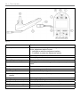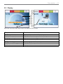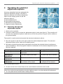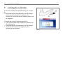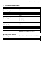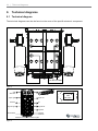
1
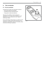
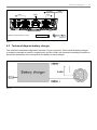
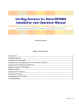
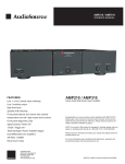
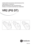
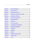
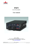
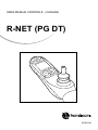
User manual CONTROLS (canada)
R-net (PG DT)
9006913A
32 |
English
© 2011 Handicare
All rights reserved.
The information provided herein may not be reproduced and/or published in any form, by print,
photoprint, microfilm or any other means whatsoever (electronically or mechanically) without the prior
written authorization of Handicare.
The information provided is based on general data concerning the construction known at the time of
the publication of this manual. Handicare executes a policy of continuous improvement and reserves
the right to changes and modifications.
The information provided is valid for the product in its standard version. Handicare can therefore not
be held liable for any damage resulting from specifications of the product deviating from the standard
configuration. Illustrations contained in the manual may deviate from the configuration of your product.
The information made available has been prepared with all possible diligence, but Handicare cannot
be held liable for any errors contained in the information or the consequences thereof.
Handicare accepts no liability for loss resulting from work executed by third parties.
Names, trade names, trademarks etc. used by Handicare may not, as per the legislation concerning
the protection of trade names, be considered as being available.
2011-07
Table of content | 33
1Introduction
1.1 This user manual
34
34
2
The controller
2.1 R-net controller
2.2Display
35
35
37
3
Driving the wheelchair with the controller
3.1 Switching the controller on or off
3.2 Driving the wheelchair 3.3Speed
3.4 Driving Profile
3.5 Selecting a profile
38
38
38
38
38
38
4
Operating the electrical adjustment options
4.1 Selecting the desired adjustment option
39
39
5Lights
40
6.Troubleshooting
41
7.
Locking the controller
42
8
Technical specifications
43
9.
Technical diagrams
9.1 Technical diagram
9.2 Technical diagram battery charger
44
44
45
34 | Introduction
1
Introduction
1.1 This user manual
This user manual will help you to use and
maintain the controller of your power wheelchair
safely. This user manual is a supplement to
Handicare’s general wheelchair user manual.
When necessary this user manual refers to
other manuals as shown below:
& Wheelchair: Refers to the general wheelchair user manual.
& Battery charger: Refers to the user manual for the battery charger.
Read this user manual and the other user
manuals referred to carefully before using
the product. If one of the user manuals was
not included with your wheelchair, please
contact your dealer immediately.
In addition to this user manual, there is also a
service manual for qualified specialists.
CONTACT HANDICARE IF YOU HAVE A
VISUAL IMPAIRMENT.
The controller | 35
2
The controller
2.1 R-net controller
A controller will usually have three basic functions:
• Driving and steering a wheelchair
• Operating electrical seat adjustments
• Charging the wheelchairs batteries
There are many different control systems for
wheelchairs on the market. If the controller on your
wheelchair does not resemble the one in figure 1,
contact your dealer.
R-net by PG Driving Technologies is a collective name
for the entire control system of the wheelchair. The
wheelchair is operated by means of a controller, which
includes the following components:
Figure 1
36 | The controller
Figure 2
Part
Function
A. Joystick
In the ‘drive’ mode: driving and steering
In the ‘adjustment options’ mode::
• Left/right to select the adjustment options
• Front/back to select the adjustment options
B. On/off switch
Switching the controller on or off
C. Horn
Warning signal with sound
D. LCD colour display screen
Display and feedback
E. “Mode” button
Changing between the ‘driving’ and the ‘adjustment options’
mode
F1: Speed regulator
Reduce driving speed (slower)
F2: Speed regulator
Increase driving speed (faster)
G. Charge connector
Input for the battery charger
H. Charge plug for the battery
charger
Connector for the battery charger
I.
Lights button
Switching the lights on or off
J.
Hazard lights
Warning signal with lights
K1: Direction indicator left
Switches the left direction indicator on or off
K2: Direction indicator right
Switches the right direction indicator on or off
L. “Profile” button
Select driving profile
The controller | 37
2.2 Display
Indoor
Seat High / Low
Figure 3 left: In the ‘drive’ position, Figure 3 right: In the ‘adjustment options’ position
Part
Function
D1: Battery indicator
Displays the power level of the battery
D2: Maximum speed
Displays the maximum speed limit as set by the user
D3: Adjustment option
Displays the selected adjustment options
D4: Profile
Displays the selected profile
D5: Speed indicator
Displays a graph of the actual speed
D6: Kilometre (/ Mileage) counter
Displays the actual speed
D7: Clock
Displays the time
38 | Driving the wheelchair with the controller
3
Driving the wheelchair
with the controller
3.1 Switching the controller on or off
To be able to drive or operate the electronic
adjustment options of the wheelchair, the
controller must be switched on. Press the on/off
button (B in figure 2).
3.2 Driving the wheelchair
Driving an electric wheelchair is done by
operating a joystick. Move the joystick forwards
and the wheelchair will also move forwards.
Steer left and right and the wheelchair will turn.
3.3 Speed
The maximum speed can be controlled by the
speed regulator on the controller (F1 en F2 in
figure 2). The speed bar on the display screen
will display the maximum speed (D2 in figure
3). Speed can be controlled with the joystick
while driving. If the joystick is moved a little, the
wheelchair will move more slowly.
3.4 Driving Profile
This controller can also be set to make the
wheelchair suitable for different driving profiles
or environments. For example, selecting
the profile for indoors will ensure that the
wheelchair will react more ‘calmly’. Once
outside, the profile can be adjusted to a more
‘robust’ setting. The name of the current profile
is displayed in the speed bar (D4 in figure 3).
R-net allows you to adjust the maximum speed
within different profiles or environments.
3.5 Selecting a profile
To switch to a different profile, just press the
‘profile’ button (L in figure 2). Press the ‘profile’
button until the most appropriate profile has
been selected.
Operating the electrical adjustment options | 39
4
Operating the electrical
adjustment options
Not every wheelchair has been equipped with
electronic adjustment options. We make a
distinction between four different adjustment
options to the seating system as per the
pictures in figure 2:
A: Seat tilt adjustments
B: Seat high/low adjustments
C: Backrest recline adjustments
D: Legrest elevation adjustments
4.1 Selecting the desired
adjustment option
A
B
C
D
Figure 2 Electrical adjustment options
1. Switch on the controller
2. Press the ‘mode’ button to select the ‘adjustment options’ mode (see figure 2). The controller will
now be in the ‘adjustment options’ mode and one of the four pictures in figure 2 will be visible on
the joystick display.
The joystick is used to select and operate the electronic adjustment options.
3. Move the joystick to the left or the right to select the desired adjustment option. The selected
adjustment option will be visible on the display screen.
4. Moving the joystick forwards and/or backwards will activate the selected electronic adjustment
option (see table 5). Move the joystick forwards or backwards until the desired adjustment option
has been attained.
Seat tilt adjustment
Seat high/low
adjustments
Backrest recline
adjustments
Legrest elevation
adjustments
Move joystick backwards
The entire chair will tilt
backwards
The entire chair will be raised
Move joystick forwards
The entire chair will tilt forwards
The backrest will tilt backwards
The backrest will tilt forwards
The legrest angle will increase,
the footplate will be raised
The legrest angle will decrease,
the footplate will be lowered
The entire chair will be lowered
Table 3 Electrical adjustment options
5. To return to the ‘drive’ mode: Press on the ‘mode’ button to select the ‘drive’ mode.
Note: If you adjust the seat height by using the high/low option or use the electrical tilt adjustment
0 - 45°, the speed will be reduced due to safety reasons.
40 | Lights
5
Lights
With the R-net it is possible to control the following
lights:
• Lights (I in figure 2)
• Hazard Lights (J in figure 2)
• Direction indicators (K1 & K2 in figure 2)
Troubleshooting | 41
6. Troubleshooting
If the wheelchair will not function while the
batteries are fully charged, check the following
points before consulting your dealer:
• Switch the controller off and then switch it on
again. Check to see if the malfunction has
been solved.
• Check if the free wheel switch was switched
to Drive.
• Check if the joystick was in the 0 position
when the controller was switched on. In
other words, the joystick must not be moved
when the controller is being switched on or
off.
Malfunctions list
An extended malfunction list can be found in
the appendix of the service manual (for qualified
specialists only). The service manual can be
found on www.handicare.com
42 | Locking the controller
7. Locking the controller
To lock the controller with the special key (H1 in figure
6):
• Insert and remove the special key into the Charger
Socket on the Controller (G in figure 6). The
controller is now locked and the following screen will
be displayed.
To unlock the controller with the special key:
• If the control system has switched off, press the On/
off (B in figure 2).
• Insert and remove the special key into the Charger
Socket on the Controller (G in figure 6). The
controller is now unlocked.
Figure 4
Technical specifications | 43
8
Technical specifications
Supply Voltage:
24 Vdc
Operating Voltage:
16Vdc to 35Vdc
Peak Voltage:
35Vdc
Reverse Battery Current:
40Vdc
PWM Frequency:
20kHz ± 0.5%
Brake Voltage:
12/24Vdc
Brake Current:
200 μ A min.
1A max.
Charger Connector:
Use only Neutrik NC3MX
Battery Charging Current:
12Arms max.
Maximum Drive Current:
R-net 60 30A
R-net 80 80A
R-net 120 120A
Indicator Outputs:
45W per side
Lighting Outputs:
21W per side
Brake Light Output:
42W total
Actuator Current:
15A max at reduced speed. 12A max at full speed.
Moisture Resistance:
Electronics to IPX4
Operating Temperature:
Non LCD Modules -25°C to +50°C
Modules with LCD Screens -10°C to +50°C
Storage Temperature:
Non LCD Modules -40°C to +65°C
Modules with LCD Screens -20°C to +65°C
EMC tested on sample wheelchair:
Susceptibility:
Tested at 30V/m to EN12184 (1999) and ANSI/ RESNA
requirements
Emissions:
To EN55022 Class B
ESD:
IEC801 part 2
44 | Technical diagrams
9. Technical diagrams
9.1 Technical diagram
The technical diagrams can also be found on the cover of the specific electronic component.
B
-+
2 x 50 A Fuse
Figure 5
dual
attendant
lights right
ISM
lights left
9006379A
mounting holes
backrest
legrest right
tilt
legrest left
high/low
tilt feedback
high/low
feedback
9002470 R-net ISM6 actuator & lights
Figure 6
9006379A
Technical diagrams | 45
seat RWD
motor
9002463 Powermodule R-net 120A
battery
seat FWD
motor
mounting holes
9006379A
Figure 7
9.2 Technical diagram battery charger
The controller’s standard configuration includes a ‘3-pin connection’. Ensure that the battery charger
is properly connected so that the ‘negative pole’ and the ‘inhibit’ are connected, enabling the system to
prevent the wheelchair from moving when the battery is being charged.
Figure 8
Dealer:
Serial number: