
1
User Manual
August 2012
ZEESC316C Rev. C
Trademarks
Snap-on, Sun and SOLUS PRO are trademarks of Snap-on Incorporated, registered in the United States and other
countries.
All other marks are trademarks or registered trademarks of their respective holders.
Copyright Information
©2011 Snap-on Incorporated. All rights reserved.
Disclaimer of Warranties and Limitation of Liabilities
The information, specifications and illustrations in this manual are based on the latest information available at the
time of printing. While the authors have taken due care in the preparation of this manual, nothing contained herein:
• Modifies or alters in any way the standard terms and conditions of the purchase, lease, or rental agreement
under the terms of which the equipment to which this manual relates was acquired.
• Increases in any way the liability to the customer or to third parties.
Snap-on reserves the right to make changes at any time without notice.
IMPORTANT:
Before operating or maintaining this unit, please read this manual carefully paying extra attention to the safety
warnings and precautions.
Visit our websites at:
http://diagnostics.snapon.com (North America)
www1.diagnostics.com.snapon/uk (United Kingdom)
For Technical Assistance Call
1-800-424-7226 (North America)
CALL +44 (0) 845 601 4736 (United Kingdom)
E-mail [email protected] (United Kingdom)
For technical assistance in all other markets, contact your selling agent.
ii
Safety Information
For your own safety and the safety of others, and to prevent damage to the equipment and
vehicles upon which it is used, it is important that these Safety Messages be read and understood
by all persons operating, or coming into contact with, the equipment.
This product is intended for use by properly trained and skilled professional automotive
technicians. The safety messages presented throughout this manual are reminders to the
operator to exercise extreme care when using this test instrument.
There are many variations in procedures, techniques, tools, and parts for servicing vehicles, as
well as in the skill of the individual doing the work. Because of the vast number of test applications
and variations in the products that can be tested with this instrument, we cannot possibly
anticipate or provide advice or safety messages to cover every situation. It is the automotive
technician’s responsibility to be knowledgeable of the system being tested. It is essential to use
proper service methods and test procedures. It is important to perform tests in an appropriate and
acceptable manner that does not endanger your safety, the safety of others in the work area, the
equipment being used, or the vehicle being tested.
It is assumed that the operator has a thorough understanding of vehicle systems before using this
product. Understanding of these system principles and operating theories is necessary for
competent, safe and accurate use of this instrument.
Before using the equipment, always refer to and follow the safety messages and applicable test
procedures provided by the manufacturer of the vehicle or equipment being tested. Use the
equipment only as described in this manual.
Read, understand and follow all safety messages and instructions in this manual, the
accompanying safety manual, and on the test equipment.
Safety Message Conventions
Safety messages are provided to help prevent personal injury and equipment damage. All safety
messages are introduced by a signal word indicating the hazard level.
! DANGER
Indicates an imminently hazardous situation which, if not avoided, will result in death or serious
injury to the operator or to bystanders.
! WARNING
Indicates a potentially hazardous situation which, if not avoided, could result in death or serious
injury to the operator or to bystanders.
! CAUTION
Indicates a potentially hazardous situation which, if not avoided, may result in moderate or minor
injury to the operator or to bystanders.
iii
Safety Information
Important Safety Instructions
Safety messages contain three different type styles.
• Normal type states the hazard.
• Bold type states how to avoid the hazard.
• Italic type states the possible consequences of not avoiding the hazard.
An icon, when present, gives a graphical description of the potential hazard.
Example:
! WARNING
Risk of unexpected vehicle movement.
• Block drive wheels before performing a test with engine running.
A moving vehicle can cause injury.
Important Safety Instructions
For a complete list of safety messages, refer to the accompanying safety manual.
SAVE THESE INSTRUCTIONS
iv
Contents
Safety Information ..................................................................................................................... iii
Contents ...................................................................................................................................... v
Chapter 1: Using This Manual ................................................................................................... 1
Conventions.................................................................................................................................. 1
Bold Text ................................................................................................................................ 1
Symbols ................................................................................................................................. 1
Terminology ........................................................................................................................... 2
Notes and Important Messages ............................................................................................. 2
Procedures............................................................................................................................. 2
Additional Manuals ....................................................................................................................... 3
Chapter 2: Introduction.............................................................................................................. 4
Functional Description .................................................................................................................. 4
Technical Specifications ............................................................................................................... 6
The Stand ..................................................................................................................................... 7
Control Buttons............................................................................................................................. 8
N/X Button.............................................................................................................................. 9
Y/a Button.............................................................................................................................. 9
Thumb Pad ............................................................................................................................ 9
Brightness/Contrast Button .................................................................................................... 9
S Button ................................................................................................................................. 9
Power Button ......................................................................................................................... 9
Connections................................................................................................................................ 10
DC Power Input.................................................................................................................... 10
Mini USB Port ...................................................................................................................... 10
USB Port .............................................................................................................................. 10
Data Cable Connector ......................................................................................................... 10
Power Supply ............................................................................................................................. 10
Vehicle Power ...................................................................................................................... 11
Battery Pack......................................................................................................................... 11
AC/DC Power Supply........................................................................................................... 12
Cables ........................................................................................................................................ 12
Data Cable ........................................................................................................................... 13
Auxiliary Power Cables ........................................................................................................ 13
Chapter 3: Getting Started....................................................................................................... 14
Demonstration Mode .................................................................................................................. 14
Supplying Power......................................................................................................................... 16
Connecting to Vehicle Power ..................................................................................................... 16
Using the Battery Pack ............................................................................................................... 17
Connecting the AC/DC Power Supply ........................................................................................ 19
Powering On the Unit ................................................................................................................. 20
Setting Up to Print ...................................................................................................................... 20
v
Contents
Connecting to a Computer.......................................................................................................... 21
Powering Off the Unit ................................................................................................................. 21
Adjusting Brightness and Contrast ............................................................................................. 21
Chapter 4: Navigation .............................................................................................................. 23
Screen Layout ............................................................................................................................ 23
Upper Toolbar ...................................................................................................................... 23
Buffer Bar ............................................................................................................................. 25
Main Body ............................................................................................................................ 25
LED Indicators ..................................................................................................................... 26
Status Bar ............................................................................................................................ 26
Making Selections ...................................................................................................................... 26
Using Easy Scroll ....................................................................................................................... 27
Screen Messages....................................................................................................................... 27
Confirmation Messages.............................................................................................................. 27
Warning Messages..................................................................................................................... 27
Error Messages .......................................................................................................................... 27
Chapter 5: Operations.............................................................................................................. 28
Selecting the Manufacturer......................................................................................................... 29
Identifying the Vehicle ................................................................................................................ 30
Selecting a System..................................................................................................................... 30
Connecting to a Vehicle.............................................................................................................. 31
Selecting from the System Main Menu....................................................................................... 31
Using the Scanner Functions ..................................................................................................... 31
Data Display......................................................................................................................... 32
Codes Menu......................................................................................................................... 32
Functional Tests................................................................................................................... 34
Generic Functions ................................................................................................................ 34
Troubleshooter ..................................................................................................................... 35
Terminating Vehicle Communication ................................................................................... 35
Exiting Scanner Mode .......................................................................................................... 36
Viewing Data Graphically ........................................................................................................... 36
Changing Screen Views....................................................................................................... 36
PID List View........................................................................................................................ 37
Text View ............................................................................................................................. 40
Graph View .......................................................................................................................... 40
Pausing Data ....................................................................................................................... 45
Clearing the Data Buffer ...................................................................................................... 45
Sorting the Data ................................................................................................................... 45
Using Cursors ...................................................................................................................... 46
Using Zoom.......................................................................................................................... 46
Saving Captured Data ................................................................................................................ 47
Viewing Saved Data ................................................................................................................... 49
Identifying Saved Files ......................................................................................................... 50
Loading Saved Files ............................................................................................................ 51
Editing Saved Data .............................................................................................................. 51
Reviewing Saved Data......................................................................................................... 51
Deleting Saved Files ............................................................................................................ 52
Copying and Moving Saved Data ........................................................................................ 52
vi
Contents
Selecting All Files................................................................................................................. 53
Viewing Saved Data Information.......................................................................................... 53
Setting a Destination for Saved Data ................................................................................... 54
Printing ....................................................................................................................................... 54
Tools Button ............................................................................................................................... 55
Custom Setup ...................................................................................................................... 55
Save Data ............................................................................................................................ 56
Custom Data List ................................................................................................................. 56
LED Setup............................................................................................................................ 57
Utilities ........................................................................................................................................ 57
Tool Setup............................................................................................................................ 58
System Tools ....................................................................................................................... 63
Easy Scroll ........................................................................................................................... 63
Connect to PC...................................................................................................................... 63
Run ...................................................................................................................................... 64
Shop Info.............................................................................................................................. 64
System Info .......................................................................................................................... 64
Chapter 6: Maintenance ........................................................................................................... 66
Cleaning and Damage Inspection .............................................................................................. 66
Battery Pack ............................................................................................................................... 66
Replacing the Battery Pack.................................................................................................. 66
Storage Tips ............................................................................................................................... 66
Disposing of the Battery Pack .................................................................................................... 67
Replacing the Display Window ................................................................................................... 67
Appendix A: Frequently Asked Questions............................................................................. 68
Can I use my other Snap-on® test adapters with this scan tool?............................................... 68
What should I do if my printer is not responding? ...................................................................... 68
What should I do if the unit doesn’t respond as expected when I press the Power button? ...... 68
Why does my unit shut down unexpectedly? ............................................................................. 69
Appendix B: Troubleshooting ................................................................................................. 70
No Communication Message ..................................................................................................... 70
Battery Pack Not Charging ......................................................................................................... 70
Unit Will Not Power On............................................................................................................... 71
Forced Shutdown ....................................................................................................................... 71
Beep Codes................................................................................................................................ 71
Appendix C: Downloading and Installing Software Updates ............................................... 72
Check for Service Upgrades Before Use.................................................................................... 72
Verifying Minimum PC Requirements......................................................................................... 72
Verifying PC System Properties........................................................................................... 73
Downloading and Installing ShopStream Connect ..................................................................... 73
Downloading Service Upgrades ................................................................................................. 75
Before You Begin ................................................................................................................. 76
Installing a Service Upgrade ................................................................................................ 76
Index .......................................................................................................................................... 79
vii
Chapter 1
Using This Manual
This manual contains tool usage instructions.
Some of the illustrations shown in this manual may contain modules and optional equipment that
are not included on your system. Contact your sales representative for availability of other
modules and optional equipment.
1.1 Conventions
The following conventions are used.
1.1.1 Bold Text
Bold emphasis is used in procedures to highlight selectable items such as buttons and menu
options.
Example:
• Press the Y/a button.
1.1.2 Symbols
Different types of arrows are used.
The “greater than” arrow (>) indicates an abbreviated set of selection instructions.
Example:
• Select Utilities > Tool Setup > Date.
The example statement abbreviates the following procedure:
1. Navigate to the Utilities button.
2. Use the Thumb Pad to navigate to and highlight the Tool Setup submenu.
3. Use the Thumb Pad to navigate to and highlight the Date option from the submenu.
4. Press Y/a to confirm the selection.
The solid arrows (e, c, d, b) are navigational instructions referring to the four directions of the
Thumb Pad.
Example:
• Press the down d arrow.
1
Using This Manual
Conventions
1.1.3 Terminology
The term “select” means highlighting a button or menu item using the Thumb Pad and pressing
the Y/a button to confirm the selection.
Example:
• Select Reset.
The above statement abbreviates the following procedure:
1. Navigate to and highlight the Reset button.
2. Press the Y/a button.
1.1.4 Notes and Important Messages
The following messages are used.
Notes
A NOTE provides helpful information such as additional explanations, tips, and comments.
Example:
i
NOTE:
For additional information refer to...
Important
IMPORTANT indicates a situation which, if not avoided, may result in damage to the test
equipment or vehicle.
Example:
IMPORTANT:
Do not force the CompactFlash® card into the slot.
1.1.5 Procedures
An arrow icon indicates a procedure.
Example:
z
To change screen views:
1. Select the View button.
The drop-down menu displays.
2. Select an option from the menu.
The screen layout changes to the format you selected.
2
Using This Manual
Additional Manuals
1.2 Additional Manuals
This tool works in conjunction with other software products. All of the required manuals are
included on the Diagnostic User Documentation CD, which was supplied with your scan tool kit.
See the appropriate manual for information regarding these products.
3
Chapter 2
Introduction
The scan tool uses Vehicle Communication Software and Fast Track® Troubleshooter software to
provide vehicle-specific trouble codes for various vehicle control systems such as engine,
transmission, antilock brake system (ABS) and more, selected functional tests, and
troubleshooting information. The scan tool can also graph live data parameters on-screen.
Figure 2-1 SOLUS PRO™
2.1 Functional Description
Figure 2-2, Figure 2-3, and Figure 2-4 show the external features of the scan tool.
4
Introduction
Functional Description
1— Left handgrip
2— Liquid Crystal Display (LCD)
3— S button
4— N/X (No) button
5— Y/a (Yes) button
6— Thumb Pad
7— Brightness/Contrast button
8— Power button
9— Right handgrip
Figure 2-2 Front view
1— Mini USB port
2— USB port
3— CompactFlash® (CF) Card Slot
4— DC power supply input
5— Data cable connector
Figure 2-3 Top view
5
Introduction
Technical Specifications
1— Stand
2— Casing hook
Figure 2-4 Back view
2.2 Technical Specifications
Display:
Liquid Crystal Display (LCD)
640 x 240 resolution
256 colors
6.2 inches (157.5 mm)
CompactFlash ® Card Slot:
The data storage CF card
IMPORTANT:
Never remove the CF card while saving data. Doing so will result in lost data.
Battery Pack:
Nickel-metal hydride
Rechargeable
Weight:
15.4 oz
437 g
External Battery Charger:
Input: 14.5–15.5 VDC, 18 watts
Output: 0–12 VDC, 1.5A
AC/DC Power Supply:
Input: 100–240 VAC @ 0.5A, 47–63 Hz
Output: 12 VDC @ 1.2A
6
Introduction
The Stand
Weight:
With battery pack:
3.37 lbs
1528 g
Dimensions:
Width:
11.85 inches
301 mm
Height:
5.63 inches
143 mm
Depth:
2.56 inches
65 mm
Operating Temperature Range:
14 to 104°F
-10 to 40°C
Storage Temperature Range:
-4 to 149°F
-20 to 65°C
Communication Protocols
Your SOLUS PRO™ scan tool supports the following OBD-II/EOBD communications protocols:
SAE J1850 (VPW)
SAE J1850 (PWM)
ISO 9141-2
ISO 14230-4 (KWP 2000)
ISO 15765-4 (CAN)
In addition, the vehicle communications software allows you to access “enhanced” diagnostic
information for specific North American, Japanese, and Korean vehicle manufacturers.
2.3 The Stand
The scan tool has a built-in, metal stand attached to the back. When the stand is not in use, it is
secured to the back of the unit by an integrated casing hook (Figure 2-4 on page 6).
When extended, the stand allows the unit to rest at a 45° angle for hands-free viewing
(Figure 2-5).
7
Introduction
Control Buttons
Figure 2-5 Stand extended
The stand can also be extended to a hanging position by pressing the left side towards the right
and rotating forward (Figure 2-6).
Figure 2-6 Stand in hanging position
2.4 Control Buttons
This scan tool has the following control buttons (Figure 2-2 on page 5):
•
•
•
•
•
•
No (N/X) button
Yes (Y/a) button
Thumb Pad
Brightness/Contrast button
S button
Power button
8
Introduction
2.4.1
Control Buttons
N/X
Button
The N/X button is used to do the following:
•
•
•
•
2.4.2
Y/a
To exit a menu or program.
To close an open list and return to the previous menu.
To answer “No” when a Yes or No choice is given.
To return to the main menu.
Button
The Y/a button is used to do the following:
• To select the item you highlighted using the Thumb Pad.
• To answer “Yes” when a Yes or No choice is given.
2.4.3 Thumb Pad
The Thumb Pad moves the highlight, allowing vertical and horizontal on-screen movement. The
Thumb Pad is typically used in combination with the Y/a and N/X buttons.
2.4.4 Brightness/Contrast Button
The Brightness/Contrast button opens the dialog box that allows you to adjust the screen for
optimum viewing. See “Adjusting Brightness and Contrast” on page 21 for details.
2.4.5 S Button
The S button can be customized to perform different functions from the Utilities > Tool Setup
menu. See “S Button” on page 61 for details.
2.4.6 Power Button
The Power button powers on and powers off this scan tool. See “Powering On the Unit” on
page 20 and “Powering Off the Unit” on page 21 for details.
The Power button is also used to force the scan tool to shut down. This feature should only be
used if the tool is not performing correctly, such as the display locks-up or data is not updating.
z
To perform a forced shutdown:
1. Press and hold down the Power button for five seconds.
2. The scan tool sounds a series of beeps, then turns off.
The unit can now be restarted.
9
Introduction
Connections
2.5 Connections
This scan tool uses the following connections (Figure 2-3 on page 5):
•
•
•
•
DC power adapter input
Mini USB port
USB port
Data cable connector
2.5.1 DC Power Input
The AC/DC power supply provides power to the scan tool through the DC power input on top of
the unit (Figure 2-3 on page 5). For related information, see the following sections:
• “AC/DC Power Supply” on page 12
• “Connecting the AC/DC Power Supply” on page 19
2.5.2 Mini USB Port
This scan tool has a Mini USB port for connecting the scan tool to a PC.
2.5.3 USB Port
This scan tool has a USB port for connecting computer peripherals, such as a printer, a keyboard,
or a mass storage device.
2.5.4 Data Cable Connector
The connector on the data cable attaches to adapters that in turn attach the scan tool to a vehicle
for testing.
For related information, see the following sections:
• “Cables” on page 12
• “Connecting to Vehicle Power” on page 16
2.6 Power Supply
This scan tool can receive power from three sources:
• Vehicle power
• Battery pack (rechargable)
• AC/DC power supply
For related information, see “Supplying Power” on page 16.
10
Introduction
Power Supply
2.6.1 Vehicle Power
This scan tool can receive 12V vehicle power via the data cable either by itself or in conjunction
with the optional auxiliary power cables.
For related information, see the following sections:
• “Data Cable Connector” on page 10
• “Cables” on page 12
• “Connecting to Vehicle Power” on page 16
2.6.2 Battery Pack
The scan tool can be powered by a rechargeable nickel-metal hydride battery pack installed in the
unit behind the right handgrip (Figure 2-7).
Figure 2-7 Battery pack partially removed
The internal battery allows you to power the scan tool, identify the test vehicle, and view the
connection message prior to connecting the scan tool to the vehicle. The connection message lets
you know which cable adapters and keys are used to connect to the vehicle, and also provides the
location of the vehicle data link connector (DLC). Once connected to the vehicle scan tool power
must be provided either through the DLC or by the auxiliary power cables when performing vehicle
tests or accessing data. A no communication message displays if vehicle power is not available to
the scan tool.
IMPORTANT:
A fully-charged battery pack should be installed in the scan tool whenever you are testing a
vehicle, even though the scan tool can operate on vehicle power without the battery installed. The
battery pack compensates for voltage drops caused by engine cranking.
Battery Charger
The battery pack is recharged by an external battery charger (Figure 2-8). See “Using the Battery
Pack” on page 17 for information on charging and installing the battery pack.
The battery charger uses the same AC/DC power supply that can also be used to power the scan
tool. See “AC/DC Power Supply” on page 12 for more details.
11
Introduction
Cables
Figure 2-8 Battery and battery charger
2.6.3 AC/DC Power Supply
This scan tool can be powered from a wall socket using the AC/DC power supply (Figure 2-9). The
AC/DC Power Supply provides a constant 12V, and must be used when updating the scan tool
software to prevent accidental power loss. The power supply also helps preserve battery life
during operations that do not require a connection to the vehicle, such as using Demonstration
mode or reviewing and managing saved data files.
Figure 2-9 AC/DC power supply
For related information, see the following sections:
• “DC Power Input” on page 10
• “Connecting the AC/DC Power Supply” on page 19
2.7 Cables
This scan tool uses the following cables:
• Data cable
• Auxiliary power cables, lighter and battery, optional.
12
Introduction
Cables
2.7.1 Data Cable
The data cable (Figure 2-10) is included with your scan tool and uses interchangeable test
adapters for connecting to vehicle diagnostic connectors.
Figure 2-10 Data Cable
Captive screws secure the data cable ends to the scan tool and test adapter. An optional data
cable extension is available.
2.7.2 Auxiliary Power Cables
Two auxiliary power cables, the Lighter Power Cable (Figure 2-11) and the Battery Power Cable
(Figure 2-12), are available as an option. The auxiliary cables are used for testing vehicles without
battery power on the diagnostic connector.
Figure 2-11 Lighter Power Cable
Figure 2-12 Battery Power Cable
Refer to the Accessory Guide, included with your kit, for a complete listing of accessories and
replacement parts.
13
Chapter 3
Getting Started
The following steps get you started using the scan tool:
1. Familiarize yourself with SOLUS PRO™ controls and connections. Refer to “Control Buttons”
on page 8 for details.
2. Charge the battery. Allow two to three hours for charging. Refer to “Using the Battery Pack” on
page 17 for details.
i
NOTE:
Use battery power for Vehicle identification purposes only (example: locate the data link connector
(DLC) and identify the adapter and keys required for vehicle communication). Always operate your
SOLUS PRO™ with the battery pack installed.
3. When fully charged insert the battery pack in the battery slot. See “To install the battery pack:”
on page 18 for details.
4. Press the Power button to turn the scan tool on.
Once the tool is powered up, you can use Demonstration mode to become familiar with scan
tool navigation and functionality without connecting to a vehicle.
3.1
Demonstration Mode
The scan tool contains programs to demonstrate scan tool test capabilities without actually
connecting to a vehicle. Sample vehicle data with mock test results are provided to help you
become familiar with menus, navigation, and basic operations.
z
To use the General Motors demonstration:
1. Connect the AC/DC power supply to a wall socket and to the DC Power Supply Input on the
tool. See “Connecting the AC/DC Power Supply” on page 19 for details.
2. Press the Power button to turn the scan tool on.
3. From the Scanner menu, highlight Scanner Demo, then press Y/a (Figure 3-1).
Figure 3-1 Scanner menu selection for Demonstration Mode
4. After the database loads, a series of VIN and vehicle equipment requests display.
5. Press Y/a to accept the default setting for each screen request until you reach the Select
System menu.
14
Getting Started
Demonstration Mode
6. Highlight any of the systems on the menu, and Press Y/a to select.
The vehicle connection message displays.
7. Press Y/a to confirm and open the system Main Menu.
8. To begin the demonstration, select from any of the menu options (example: Data Display,
Codes Menu, Functional Tests, Troubleshooter).
i
NOTE:
The Demonstration contains actual data captured while driving a 2001 Chevrolet Tahoe. Look for
the throttle position (TP) sensor dropout while analyzing the data in Graphing mode.
9. To exit the demonstration, press N/X until you return to the system Main Menu.
10. To return to the Main Menu, highlight the View button on the upper toolbar and press N/X.
A demonstration program is also available for Global OBD-II/EOBD.
z
To use the Global OBD-II/EOBD demonstration:
1. Highlight Global OBDII on the scan tool Main Menu and press Y/a.
Figure 3-2 Global OBD-II/EOBD menu selection
2. Press Y/a to open the Generic OBDII/EOBD database.
3. Highlight OBD Training Mode and press Y/a.
Figure 3-3 Sample OBD Training Mode selection
4. Highlight Start Communication on the Main Menu OBD, and Press Y/a to select.
5. Press Y/a when the vehicle connection message displays.
6. The ECU/Protocol Information screen displays, PressY/a to continue.
7. Highlight any of the item on the Select Service menu, and Press Y/a to select.
Simulated test data now displays.
8. To exit, press N/X until you return to the Main Menu OBD.
9. Highlight End of Diagnose at the bottom of the list and press Y/a.
10. Highlight the View button on the upper toolbar and press N/X to return to the Main Menu.
15
Getting Started
3.2
Supplying Power
Supplying Power
There are three ways to supply power to the scan tool:
• Connect to vehicle power
• Use the battery pack
• Connect to an AC adapter
For related information, see “Power Supply” on page 10.
i
3.3
NOTE:
To extend the life of your battery pack, always power the scan tool with vehicle power or use the
AC/DC Power Supply. The battery pack is intended to be used during the vehicle identification
process and to get vehicle connection information.
Connecting to Vehicle Power
You need the following to connect the scan tool to vehicle power:
• Data cable
• Test adapter
For related information, see the following sections:
• “Data Cable Connector” on page 10
• “Vehicle Power” on page 11
• “Connecting to Vehicle Power” on page 16
z
To connect to vehicle power:
1. Connect one end of the data cable to the data cable connector on the top of the scan tool
(Figure 2-3 on page 5).
2. Connect the other end of the data cable to the appropriate test adapter. The scan tool displays
relevant adapter and key usage for the identified vehicle.
3. Connect the test adapter to the vehicle diagnostic connector. The scan tool displays the
location of the diagnostic connector.
4. Turn the ignition on.
For vehicles that do not supply power through the diagnostic connector, you must use the optional
auxiliary power cables (see “Auxiliary Power Cables” on page 13).
i
NOTE:
Do not plug the Lighter Power Cable into the DC power input port on the top of the unit. Vehicle
power must be supplied to the test adapter for the scan tool to communicate with the vehicle.
16
Getting Started
z
Using the Battery Pack
To use auxiliary power cables:
1. Connect the required test adapter to the data cable (Figure 3-4).
1
2
3
1— Lighter Power Cable, large end
2— Lighter Power Cable, small end
3— Vehicle test adapter
Figure 3-4 Auxiliary power cable connections
2. Plug the small end of the Lighter Power Cable into the port on the test adapter.
3. Plug the large end of the Lighter Power Cable into the socket of the Battery Power Cable.
4. Connect the clamps of the Battery Power Cable to the vehicle battery. Be sure to observe
correct polarity when connecting to the vehicle battery.
3.4
Using the Battery Pack
The scan tool comes with a rechargeable nickel-metal hydride battery pack and an external
battery charger.
For related information, see the following sections:
•
•
•
•
“Battery Pack” on page 11
“Battery Charger” on page 11
“Replacing the Battery Pack” on page 66
“Battery Pack Not Charging” on page 70
Before using the battery pack for the first time, you must fully charge it.
z
To charge the battery pack:
1. Remove the battery from the scan tool:
a. Remove the right handgrip from the scan tool.
b. Press down on the retaining tab on the side of the battery pack and slide the battery pack
out of the battery slot.
2. Plug the AC/DC power adapter into the DC power jack of the battery charger.
17
Getting Started
i
Using the Battery Pack
NOTE:
Do not put a hot battery pack in the battery charger unit. Allow the battery pack to cool first. For
optimal battery charging, the ideal room temperature is 77°F (25°C) ±5°.
3. Vertically insert the battery pack into the charger (Figure 3-5).
1
2
3
4
1— Battery pack
2— Battery charger
3— DC power jack
4— Charge status light
Figure 3-5 Battery pack charge orientation
When charging begins, a red status light displays.
4. Let the battery pack charge until a steady green status light displays.
When the battery pack is too hot, too cold, or unable to hold a charge, both red and green
charge status lights will flash. If the charge status lights flash for more than two hours, the
battery pack may need replacing. See “Battery Pack Not Charging” on page 70.
i
NOTE:
A fully discharged battery pack takes four hours to charge.
z
To install the battery pack:
1. Remove the right handgrip.
2. Insert the battery pack into the battery slot (Figure 3-6).
3. Replace the handgrip.
18
Getting Started
Connecting the AC/DC Power Supply
1
2
3
1— Battery slot
2— Battery pack
3— Right handgrip
Figure 3-6 Battery pack installation
z
To extend the life of the battery pack:
• Before recharging the battery pack, let it become completely discharged.
A warning message displays four minutes before the battery pack is completely discharged.
Figure 3-7 Sample low battery warning
z
To continue working after the battery warning displays:
• Connect the AC/DC power adapter.
The scan tool may not be able to communicate with the vehicle if 12-volt vehicle power is not
available to the test adapter.
3.5
Connecting the AC/DC Power Supply
The AC/DC power supply (included) provides power from a wall socket. For related information,
see the following sections:
• “DC Power Input” on page 10
• “AC/DC Power Supply” on page 12
19
Getting Started
z
Powering On the Unit
To connect an AC/DC power supply:
1. Plug the 2.5 mm end of the AC/DC power supply cord into the DC port on the tool (Figure 3-8).
Figure 3-8 DC power supply input
2. Plug the other end of the power adapter into an appropriate wall socket.
3.6
Powering On the Unit
When a charged battery pack is installed, you can power on your scan tool.
For related information, see “Powering Off the Unit” on page 21.
z
To power on the scan tool:
• Press the Power button (Figure 2-2 on page 5).
The unit beeps and the main menu screen (Figure 3-9) displays after a few seconds.
1
2
3
1— Scanner—use to access vehicle tests
2— Saved Data—use to access files stored in memory
3— Utilities—use to access tool setup and operation functions
Figure 3-9 Sample main menu
3.7
Setting Up to Print
This scan tool prints when connected to a compatible printers with a USB cable. Before you can
use the Print button in the upper toolbar, you must do the following:
1. Set up the printer.
2. Connect a USB cable between the scan tool and the printer.
3. Configure the scan tool to print.
20
Getting Started
z
Connecting to a Computer
To set up the printer:
• Refer to your printer’s documentation for powering and paper loading instructions.
z
To configure the scan tool to print:
• Select a printer manufacturer and port from the Utilities > Tool Setup > Printer dialog box.
See “Printer” on page 59 for details.
3.8
Connecting to a Computer
Connecting your scan tool to a computer for file sharing requires the use of the optional
ShopStream Connect™ software. ShopStream Connect is a free software program that can be
downloaded from the Internet at software.snapon.com.
3.9
Powering Off the Unit
Use the Power button (Figure 2-2 on page 5) to turn the scan tool off.
IMPORTANT:
Do not attempt to turn off the scan tool with the power button while it is operating in Scanner mode.
Exit Scanner mode before powering down.
z
To power off the unit:
1. Make sure you have exited the vehicle communication software as described in “Terminating
Vehicle Communication” on page 35.
2. Exit Scanner mode as described in “Exiting Scanner Mode” on page 36.
3. Press the Power button.
The Turn off dialog box displays (Figure 3-10).
Figure 3-10 Turn off dialog box
4. Press Y/a to turn the power off, or press N/X to cancel.
3.10
Adjusting Brightness and Contrast
The Brightness/Contrast button lets you to adjust the screen for optimum viewing.
21
Getting Started
z
Adjusting Brightness and Contrast
To adjust screen brightness and contrast:
1. Press the Brightness/Contrast button.
The Set Brightness/Contrast dialog box displays (Figure 3-11).
2. Select a slider control using the right c or left e arrow.
3. Press the up b or down d arrow to increase or decrease Brightness and Contrast.
4. Press N/X to close the Set Brightness/Contrast dialog box when you are finished.
2
1
1— Brightness slider control
2— Contrast slider control
Figure 3-11 Set Brightness/Contrast dialog box
22
Navigation
Chapter 4
4.1
Screen Layout
Scan tool screens (Figure 4-1) typically include the following sections:
• The upper toolbar contains test controls.
• The main body displays menus and test data.
1
2
3
4
1— Upper toolbar
2— Main body
3— LED Indicators
4— Status bar
Figure 4-1 Sample screen layout
4.1.1 Upper Toolbar
The upper toolbar (Figure 4-2 and Figure 4-3) controls vary depending on the mode and stage of
operations. Toolbar buttons and their function are shown in Table 4-1.
Figure 4-2 Sample upper toolbar—Text view
Figure 4-3 Sample upper toolbar—Graph view
Table 4-1 Upper toolbar controls (sheet 1 of 2)
Name
Button
Description
View
Lets you change the way data displays
Pause
Stops data collection and lets you review the buffered data
23
Navigation
Screen Layout
Table 4-1 Upper toolbar controls (sheet 2 of 2)
Name
Button
Description
Play
Continuously captures data and stores it in the Data Buffer
Clear
Erases all data from the Data Buffer
Sort
Lets you select the order in which the data displays
Scanner
Indicates when the Scanner screen is active
Cursor
Lets you make digital amplitude measurements of graph data
Zoom
Lets you change the magnification of the data in Graph View, or
pick the number of PIDs displayed on-screen in PID List view
Snapshot
Lets you capture a snapshot using the PID Trigger or Manual
Snapshot
Save
Lets you store scanned vehicle data or save the current screen
in memory
Print
Lets you print the displayed screen or a list of the current
parameter values
Tools
Offers a shortcuts to Custom Setup, Save Data, Custom Data
List, and LED Setup. Custom Setup opens the Scanner Units
dialog box, which lets you select how certain data values
display. Save Data opens the Save Data dialog box that lets you
configure how data is saved. Custom Data List lets you select
which parameters are displayed. LED Setup lets you select
which parameters are displayed on the LEDs.
Scanner Button
When the Scanner button is selected, the background of the main body turns white, indicating that
the Text view is active (Figure 4-4) and the up b and down d arrows and the Y/a and N/X buttons
are used for screen navigation.
Figure 4-4 Active Scanner screen
24
Navigation
Screen Layout
When you select a different button from the upper toolbar using the left e and right c arrows in
Text view, the background of the main body turns gray, indicating the screen is inactive
(Figure 4-5). See “Terminating Vehicle Communication” on page 35 for more information.
Figure 4-5 Inactive Scanner screen
4.1.2 Buffer Bar
The buffer bar displays in Graph View and PID List View and indicates the amount of data the scan
tool is holding in temporary storage.
As data collects, the buffer bar fills from left to right across the screen. A full buffer is indicated by
a flashing vertical line at the right end of the buffer bar (Figure 4-6). Data continues to collect once
the buffer is full, older data is deleted one frame at a time as new data is added.
Figure 4-6 Sample full data buffer
You can adjust the percentage of data that is saved before and after the trigger through the Utilities
Menu. See “Save Data” on page 59 for details.
4.1.3 Main Body
The main body (Figure 4-7) of the screen provides prompts. The prompts guide you through
vehicle identification and task selection. Once communication is established with an electronic
control module (ECM), parameter information can be displayed.
Figure 4-7 Sample Scanner main body
25
Navigation
Making Selections
4.1.4 LED Indicators
Four LED indicators appear at the bottom of the screen and show designated operating
conditions. The LEDs can be programmed to show change of state for certain digital parameters,
which vary by manufacturer.
4.1.5 Status Bar
The status bar (Figure 4-8) at the bottom of the screen shows the test vehicle identification, the
time, the date, and a power source indicator.
Figure 4-8 Sample status bar
You can adjust how the date and time display by selecting Utilities > Tool Setup from the tool
main menu. See “Tool Setup” on page 58 for details. Power source indicator definitions are shown
in Table 4-2.
Table 4-2 Power supply indicators
Indicator
Description
Power supplied by the internal battery
Power supplied by the vehicle
Power supplied by the AC/DC Power Supply
i
4.2
NOTE:
Vehicle power is needed to ensure scan tool communication with the vehicle. Make sure the
vehicle power icon displays on the status bar before attempting to perform tests.
Making Selections
Use the following instructions to navigate the interface and make selections.
z
To navigate the upper toolbar:
• Press the left e and right c arrows of the Thumb Pad.
z
To navigate the main body:
• Press the up b and down d arrows of the Thumb Pad.
z
To make selections:
1. Highlight a button or menu option.
2. Press Y/a to confirm the selection.
26
Navigation
Using Easy Scroll
4.3
Using Easy Scroll
Instead of using the Thumb Pad to highlight an item and the Y/abutton to select it, Easy Scroll lets
you use only the Thumb Pad arrows to highlight and select items.
Easy Scroll works in the following ways:
• The up b and down d arrows navigate menus.
• The right c arrow works like the Y/a button to confirm the selection of menu items.
• The left e arrow works like the N/X button for cancelling, exiting, and closing menus.
See “Easy Scroll” on page 63 for information on activating Easy Scroll.
4.4
Screen Messages
There are three types of on-screen messages:
• Confirmations
• Warnings
• Errors
z
To manage on-screen messages:
• Press Y/a or N/X as indicated in the message.
4.5
Confirmation Messages
Confirmation messages inform you when you are about to perform an action that cannot be
reversed or when an action has been initiated and your confirmation is needed to continue.
When a response is not required, the message displays briefly then automatically disappears.
4.6
Warning Messages
Warning messages inform you when completing the selected action may result in an irreversible
change or loss of data.
4.7
Error Messages
Error messages inform you when a system or procedural error has occurred.
Examples of possible errors include:
• A cable is disconnected.
• A peripheral, such as a printer is powered off.
• A CompactFlash® card is inserted improperly.
27
Chapter 5
Operations
This section explains general scan tool operations and offers instructions for customizing certain
tool functions.
The following is an outline of basic operations.
i
NOTE:
The sequence of steps may vary depending on manufacturer or model of the test vehicle. See the
Vehicle Communication Software manuals for the test vehicle for detailed procedures.
1. Select the manufacturer—Select and load the software database for the manufacturer of the
test vehicle. See “Selecting the Manufacturer” on page 29.
2. Identify the vehicle—Identify the test vehicle to the scan tool by entering VIN characters and
answering questions. See “Identifying the Vehicle” on page 30.
3. Select the system—Enter the system to be tested (engine, transmission, ABS, etc.). See
“Selecting a System” on page 30.
4. Connect the scan tool to the vehicle—Follow the on-screen connection instructions to
connect the scan tool to the vehicle. See “Connecting to a Vehicle” on page 31.
5. Select the required test from the Scanner main menu—Select tests for the vehicle you
have identified. See “Selecting from the System Main Menu” on page 31.
Power up SOLUS PROTM
(use internal battery power)
Highlight US Domestic, Asian,
or European in the
Vehicle Comm submenu
Highlight the SCANNER button
(using the Thumb Pad)
Highlight and Press Y/
to select the vehicle:
Year,
Make,
Model,
Equipment.
Select a Vehicle System
(example; Engine,
Transmission, ABS)
NOTE: vehicle connector location
and the test adapter and keys
required for communication
displays on screen.
Highlight the Manufacturer
(example Ford, Toyota)
Press Y/
Connect SOLUS PROTM
to the test vehicle.
(SOLUS PRO now operates
on 12V vehicle power)
Select from the System Main Menu Options
Codes
(read codes in
vehicle memory)
Data
(view vehicle
parameters)
Functional Tests
(perform tests)
Generic Functions
(perform standard
OBD-II tests)
Figure 5-1 Basic scan tool operations
28
Troubleshooter
(consult experience
based information)
Operations
Selecting the Manufacturer
5.1
Selecting the Manufacturer
Vehicle manufacturers are organized into categories (Figure 5-2):
•
•
•
•
•
•
•
Previous Vehicles—for recently tested vehicles
US Domestic—for vehicles produced by US manufacturers
Asian—for vehicles produced by Japanese and Korean manufacturers
European—for vehicles produced by European manufacturers
Global OBDII—for any OBD-II vehicle
OBD Health Check—for any OBD-II/EOBD vehicle
Scanner Demo—see “Demonstration Mode” on page 14
Each category represents a software database that includes information for a group of
manufacturers. For example, select Asian to test a Nissan, even if the model being tested is
produced in the United States.
1
2
3
1— Scanner function
2— Vehicle Communication menu
3— Submenu
Figure 5-2 Scanner main menu software selection
i
NOTE:
A Years submenu displays for some selections.
z
To select the manufacturer:
1. From the main menu, select Scanner.
The Vehicle Communication menu displays (Figure 5-2):
2. Select from the submenus as necessary.
The database loads, then the first of a series of vehicle identification (ID) screens display
(Figure 5-2).
29
Operations
Identifying the Vehicle
5.2
Identifying the Vehicle
After you select the manufacturer, you are ready to identify the specific vehicle to be tested.
i
NOTE:
The exact procedure varies depending on the manufacturer. Screen prompts will guide you
through the procedure.
z
To identify a vehicle:
1. Once the database loads, the first vehicle identification (ID) screen displays (Figure 5-3).
2. Press the up b and down d arrows on the Thumb Pad until the correct character is shown,
then press Y/a.
Figure 5-3 Sample Vehicle ID screen
3. Continue by entering VIN characters and pressing Y/a or N/X to answer the on-screen
questions as necessary.
Once the vehicle identification is complete, a Select System menu displays (Figure 5-4).
5.3
Selecting a System
You must select the vehicle control system you wish to test (Figure 5-4).
z
To select a system:
1. Press the up b and down d arrows so the cursor is at the system you wish to test.
2. Press Y/a to select.
Figure 5-4 Sample system selection screen
30
Operations
5.4
Connecting to a Vehicle
Connecting to a Vehicle
Connection instructions prompt you to connect the scan tool to a vehicle diagnostic connector for
testing (Figure 5-5).
Figure 5-5 Sample connection instruction screen
Follow the on-screen connection instructions, then press Y/a to open the system Maim Menu.
5.5
Selecting from the System Main Menu
Depending on the vehicle, a number of options may be available on the system Main Menu
(Figure 5-6). Scanner options are explained in “Using the Scanner Functions” below.
Figure 5-6 Sample system Main Menu
5.6
Using the Scanner Functions
System main menu options vary by make and model and may include the following:
• Data Display— displays data parameter information from the vehicle control module.
selecting may open a submenu of viewing options.
• Codes Menu—displays diagnostic trouble code (DTC) records from the vehicle control
module. selecting may open a submenu of viewing options.
• Service Codes—performs self-tests and displays codes after performing these tests.
• Functional Tests—provides specific subsystem and component tests. The tests vary
depending on the manufacturer and model.
• Actuator Tests—similar to functional tests, these tests check the operation of certain
actuators, such as solenoid valves and relays.
31
Operations
Using the Scanner Functions
• System Tests—provides specific subsystem testing.
• Generic Functions—lets you access Generic OBD-II/EOBD functions.
• Troubleshooter—provides step-by-step procedures, integrating parameter data and
retrieving trouble codes when appropriate, for specific symptoms of the identified vehicle.
5.6.1 Data Display
Selecting Data Display on the system Main Menu has one of the following results:
• A submenu of data viewing choices displays.
• Vehicle data displays.
A submenu displays when more than one data viewing mode is available on the identified vehicle
(Figure 5-7).
Figure 5-7 Sample data submenu
On some models, the engine must be started or cranked before data can be displayed. For these
models, a “Waiting to Communicate” message displays if the engine was not cranked or started.
Data Screens
When a Data selection is made, the screen displays the data list for the selected module.The
items available for any control module vary from one vehicle to another.
The top line of the display remains fixed. In some cases, the second line shows the test mode
name and also indicates whether or not the vehicle can be driven during testing.
5.6.2 Codes Menu
Selecting Codes Menu from the system main menu opens a list of data parameter viewing
options. Codes Menu selections typically include:
•
•
•
•
Trouble Codes
Clear Codes
Freeze Frame/Failure Records
DTC Status
32
Operations
Using the Scanner Functions
Trouble Codes
Trouble Codes displays a list of diagnostic trouble codes (DTCs) stored in the selected electronic
control module (ECM). Selecting opens a submenu of DTC viewing options on some models.
Submenu options allow you to view more detailed DTC information (Figure 5-8).
Figure 5-8 Sample Trouble Codes submenu
Clear Codes
The scan tool clears trouble codes from the control module memory on some vehicles. If this
function is not available on the test vehicle, Clear Codes does not appear as a menu option.
Freeze Frame/Failure Records
This selection displays the DTC that was set, along with corresponding data, when the ECM
commanded the malfunction indicator lamp (MIL) to turn on.
DTC Status
This selection allows you to see if a particular DTC caused the MIL to turn on.
z
To check DTC status
1. Select DTC Status from the Codes Menu.
The DTC Status screen displays with the cursor at the second character of the code
(Figure 5-8).
Figure 5-9 Sample DTC Status entry screen
2. Use the up b and down d arrows to enter the second character.
3. Press Y/a and the cursor moves to the third character.
4. Use the up b and down d arrows to enter the third character.
33
Operations
Using the Scanner Functions
5. Press Y/a and the cursor moves to the fourth character.
6. Use the up b and down d arrows to enter the fourth character.
7. Press Y/a and the cursor moves to the fifth character.
8. Use the up b and down d arrows to enter the fifth character.
9. Press Y/a and the status of the selected DTC displays (Figure 5-10).
Figure 5-10 Sample DTC Status screen
10. Press N/X to return to the DTC status entry screen.
11. Press N/X again to return to the Codes menu.
5.6.3 Functional Tests
The Functional Tests selection is used to access vehicle-specific subsystem and component
tests. Available tests vary by manufacturer, year, and model, and only the available tests display
in the menu.
There are four general types of functional test operations:
• Information Tests—are read-only tests, like selecting “VIN” from a Functional Tests menu to
display the VIN of the identified vehicle.
• Toggle Tests—switch a component, such as a solenoid, relay, or switch, between two
operating states. The terms “on/off,” “open/clsd” (open/closed),” “enab/disa” (enable/disable),
and others may be used to identify the different states.
• Variable Control Tests—command a certain value for a system or component, such as
varying the spark timing in 1° increments or the EGR valve duty cycle in 10% increments.
• Reset Tests—reset the adaptive, or learned, values that are stored in the control module.
5.6.4 Generic Functions
The Generic Functions selection opens a menu of available OBD-II/EOBD functions on 1996
and newer vehicles. Menu options typically include:
•
•
•
•
•
•
Freeze Frame—displays data stored in ECM memory when a DTC is set
Readiness Monitors—displays the status of the OBD-II/EOBD required monitors
Mode 6 Non Cont—displays the status of non-continuous OBD-II/EOBD monitors
Mode 9 Calib. ID—displays the calibration identification numbers of the vehicle ECMs
Mode 9 (CVN)—displays the calibration verification numbers of the vehicle ECM
Mode 9 (VIN)—displays the vehicle identification number
34
Operations
Using the Scanner Functions
5.6.5 Troubleshooter
The Troubleshooter selection is on the system Main Menu only if Fast-Track® Troubleshooter
information is available. Fast-Track® Troubleshooter is a database of experience-based
information of validated real-world repair strategies that have been compiled by top-notch
technicians since 1988.
Select Troubleshooter, and a system menu may display (Figure 5-11).
Figure 5-11 SampleTroubleshooter system menu
Select a system and a Troubleshooter Menu similar to Figure 5-12 displays.
Figure 5-12 Sample Troubleshooter Menu
Troubleshooter menus vary by make, model, and system.
Certain information available from a Troubleshooter tip, such as circuit and connector diagrams,
may not display properly on the scan tool screen. In this case, the Troubleshooter tip directs you
to a numbered reference. These References, which allow you to access more information about
the vehicle in the Fast-Track Reference database, are available on line. Simply open your web
browser to www.askatech.com and click on Fast-Track Reference.
5.6.6 Terminating Vehicle Communication
You must terminate communication with the vehicle control module in order to safely shut down
the scan tool. Use the following procedure to terminate correctly.
z
To terminate communication:
• Press N/X until you reach the main menu (Figure 5-13).
35
Operations
Viewing Data Graphically
Figure 5-13 Sample main menu
A “stopping communication” message appears briefly before the main menu displays.
5.6.7 Exiting Scanner Mode
Always exit Scanner mode before powering off. Exiting Scanner mode is different depending on
the view option selected.
IMPORTANT:
Exiting Scanner mode does not ensure that you have safely terminated communication with a
vehicle. See “Terminating Vehicle Communication” on page 35.
z
To exit Scanner mode from text screens:
1. Use right c and left e arrows to scroll the highlight off of the Scanner button.
2. Press N/X to return to the main menu.
z
To exit Scanner mode from PID List or Graphs views:
• Press N/X until you return to the main menu.
5.7
Viewing Data Graphically
The scan tool provides multiple options for viewing and sorting collected data.
5.7.1 Changing Screen Views
Data can be viewed in the following formats:
• PID List view
• Text view
• Graph view
36
Operations
Viewing Data Graphically
z
To change screen views:
1. Select the View button to open the drop-down menu (Figure 5-14).
Figure 5-14 Sample View menu
2. Select an option from the menu and the screen layout changes to the selected format.
5.7.2 PID List View
The parameter identification (PID) List view displays all parameters in a table format. As many as
eight parameters (Figure 5-15) can be viewed on one screen depending on the Zoom setting.
Figure 5-15 Sample PID List view
z
To adjust the Zoom setting
1. Select the Zoom button on the upper toolbar to open the dropdown menu (Figure 5-16).
Figure 5-16 Sample Zoom dropdown menu
2. Highlight a menu option and press Y/a.
The menu closes and the display changes to show the selected number of PIDs.
Reviewing PIDs
You can review up to 2000 frames of collected PID data by pausing the screen (Figure 5-17).
37
Operations
Viewing Data Graphically
1
2
3
4
1— Pause/Play button
2— Review
3— PID data
4— Buffer bar indicator
Figure 5-17 Sample paused upper toolbar in PID View
z
To review collected PID data:
1. Select the Pause button to stop the data collection.
2. Select the Review button and use the right c and left e arrows to scroll through the data
stored in the buffer. The status bar indicator shows your position in the stored data.
3. Press N/X to release the Data Review control.
4. Select the Play button to cancel the pause and resume live data collection.
Clearing the Buffer
The Clear button on the toolbar erases all of the data in the buffer.
z
To clear the data buffer:
1. Select Clear on the upper toolbar.
A confirmation screen displays.
2. Press Y/a to erase the data, N/X to cancel.
New data begins saving after the buffer has been cleared.
Sorting the PID List
The Sort button on the toolbar allows you to arrange the parameter list three ways:
• Factory Sort—in the order transmitted by the electronic control module (ECM)
• A-Z Sort—in alphabetical ascending order
• Z-A Sort—in alphabetical descending order
z
To sort the PID List:
1. Select the Sort button on the upper toolbar.
2. Highlight an option on the dropdown menu (Figure 5-18).
38
Operations
Viewing Data Graphically
Figure 5-18 Sample sort dropdown menu
3. Press Y/a to sort.
i
NOTE:
Any PIDs that were locked are unlocked whenever a selection is made from the Sort button.
Locking PIDs
You can lock PIDs in place for customized list viewing.
z
To lock a PID:
1. From the upper toolbar, press the down d arrow.
2. Select the PID you want to lock.
The parameter menu displays (Figure 5-19).
Figure 5-19 Sample parameter menu
3. Select Lock.
A lock icon displays to the left of the parameter name (Figure 5-20) and the locked PID stays
in place when your scroll through the PID list.
Figure 5-20 Locked PID sample
4. Repeat the above steps to lock multiple PIDs.
5. Press N/X to return to the upper toolbar.
39
Operations
Viewing Data Graphically
z
To unlock PIDs:
1. Select a locked PID and when the parameter menu displays, select Unlock.
The lock icon disappears and the parameter can be scrolled as before.
2. Press N/X to return to the upper toolbar.
i
NOTE:
Select Unlock All to release all of the locked parameters at once.
5.7.3 Text View
Text view displays parameters as plain text (Figure 5-21).
Figure 5-21 Sample Text view
5.7.4 Graph View
The Graph view let you view data in line graph format (Figure 5-22).
1
2
3
1— Maximum value of captured data
2— Current value
3— Minimum value of captured data
Figure 5-22 Sample 1 Graph screen
Parameter Menu
When viewing data in the Graph view, the scan tool offers a parameter menu (Figure 5-23) with
the following options:
40
Operations
Viewing Data Graphically
•
•
•
•
Lock—lets you lock a parameter into position to compare readings.
Unlock—lets you unlock a single parameter.
Unlock All—lets you unlock all locked parameters.
Scale—lets you rescale the minimum and maximum graph values captured within the last
2000 points.
• Scale All—lets you rescale all the minimum and maximum graph values.
• Set Trigger Levels—lets you specify automatic screen-freezing conditions when
Snapshot > PID Trigger is used.
• Clear Trigger Levels—lets you remove set trigger conditions from the selected parameter.
• Clear All Trigger Levels—lets you remove set trigger conditions from all parameters
simultaneously.
Figure 5-23 Sample parameter menu
z
To lock a parameter:
1. From the upper toolbar, press the down d arrow to highlight the first parameter graph.
2. Select the parameter you want to lock.
The parameter menu displays.
3. Select Lock.
A lock icon displays (Figure 5-22). The locked graph will not move when you scroll through the
remaining graphs.
Figure 5-24 Lock icon indicating a locked parameter
4. Scroll other parameters into place to compare readings.
z
To unlock a parameter:
1. Select the locked parameter.
The parameter menu displays.
2. Select Unlock.
The lock icon disappears and the parameter can be scrolled as before.
41
Operations
Viewing Data Graphically
z
To unlock all parameters:
1. When a PID is locked on-screen, select any parameter.
The parameter menu displays.
2. Select Unlock All.
All of the lock icons disappear and all of the locked parameters can now be scrolled.
z
To scale a parameter:
1. Select a parameter.
The parameter menu displays.
2. Select Auto Scale.
The minimum and maximum graph values are reset for the selected parameter.
z
To manually scale a parameter:
1. Select a parameter.
The parameter menu displays.
2. Select Manual Scale.
A line displays across the top of the graph along with a box that displays the maximum
recorded value (Figure 5-25).
Figure 5-25 Sample manually scaling a parameter
3. Use the down d arrow to move the maximum displayed value into position.
4. Press Y/a to set the selected value.
5. Press Y/a to scale the minimum value.
6. Use the up b arrow to move the maximum displayed value into position.
7. Press Y/a to set the selected value.
8. Press N/X to exit manual scale.
The top and bottom of the graph is now clipped so that only the portion that falls between the
selected minimum and maximum values displays.
z
To scale all parameters:
1. Select a parameter.
The parameter menu displays.
2. Select Scale All.
The minimum and maximum graph values are reset for all of the parameters.
42
Operations
Viewing Data Graphically
z
To set trigger levels:
1. Select a parameter.
The parameter menu displays.
2. Select Set Trigger Levels.
The active trigger level line displays as a solid line together with a position value (Figure 5-26).
Figure 5-26 Sample active trigger line
i
NOTE:
Both an upper and lower trigger level must be set.
3. Adjust the upper trigger level using the up b and down d arrows to place the trigger level line
where you want it on the PID graph.
4. Press Y/a to set the trigger.
When set, the solid black line changes to a dotted line and the position value no longer
displays (Figure 5-27).
1
2
1— Upper trigger level
2— Lower trigger level
Figure 5-27 Sample set trigger levels
5. Adjust the lower trigger level using the up b and down d arrows and press Y/a to set it.
The area between the two trigger levels establishes the triggering condition. Any data points
that register outside of your set condition trigger the on-screen graphing to pause.
6. Press Y/a if you want to switch between trigger level lines during the setting process.
7. When you finish setting your trigger level, press N/X.
i
NOTE:
Only three PIDs can have trigger levels set at one time, but only one of the conditions needs to be
satisfied for triggering to occur.
43
Operations
Viewing Data Graphically
z
To arm PID Triggering:
1. From the upper toolbar, select Snapshot > PID Trigger.
2. Select from the dropdown menu (Figure 5-28):
– PID Trigger—begins collecting when a signal outside the set conditions occurs
– Manual—begins collecting the next time the Snapshot button is selected
Figure 5-28 Sample armed triggering
A check mark displays next to the selected menu option.
Trigger Delay
Once the trigger is detected, a collecting snapshot window opens (Figure 5-29).
Figure 5-29 Sample collecting snapshot window
When a snapshot is taken, the scan tool retrieves some of the buffered data, captures data at the
trigger point, and records additional data after the trigger point. This gives you a complete picture
of what was happening before the fact, what occurred at the trigger point, and what happened
after the fact.
The amount of data collected is specified by the % After Trigger setting, found in Utilities >
Tool Setup > Save Data. You can manually stop the snapshot by pressing Y/a at any time during
the data collection.
Once data collection is finished, graphing on-screen stops and the Pause button automatically
changes to the Play button. A vertical line now appears on each of the data graphs to indicate the
triggering point. The trigger line on the parameter that triggered the snapshot is a different color
than those on the other graphs (Figure 5-30). This makes it easy to determine which parameter
caused the trigger.
Figure 5-30 Sample trigger detection lines
44
Operations
Viewing Data Graphically
z
To restart graphing:
• Select the Play button (Figure 5-30).
z
To clear trigger levels:
1. Select a parameter.
The parameter menu displays.
2. Select a Clear option.
– Clear Trigger Levels—removes the trigger settings from the one selected PID only.
– Clear All Trigger Levels—removes the trigger settings from all of the PIDs.
z
To disarm PID Triggering:
• Select Snapshot > PID Trigger.
The check mark next to the menu option disappears.
5.7.5 Pausing Data
The Pause button temporarily stops, or “pauses”, data collection (Figure 5-31).
Figure 5-31 Pause button viewing “live-screen” data
When the Pause button is selected, it changes to the Play button (Figure 5-32), which resumes
data collection.
Figure 5-32 Play button—viewing “paused-screen” data
5.7.6 Clearing the Data Buffer
The Clear button on the toolbar erases all of the data in the buffer. A confirmation screen displays
when the clear button is selected. New data begins saving after the buffer has been cleared.
5.7.7 Sorting the Data
The Sort button on the toolbar allows you to arrange the parameter list three ways:
• Factory Sort—in the order transmitted by the electronic control module (ECM)
• A-Z Sort—in alphabetical ascending order
• Z-A Sort—in alphabetical descending order
45
Operations
Viewing Data Graphically
z
To sort the data list:
1. Select the Sort button on the upper toolbar.
2. Highlight an option on the dropdown menu:
3. Press Y/a to sort.
i
NOTE:
Any locked parameters are unlocked whenever a selection is made from the Sort button.
5.7.8 Using Cursors
When data is paused in Graph view, the Cursor button displays on the upper toolbar
(Figure 5-33), which allows you to view digital amplitude measurements of frozen data.
Figure 5-33 Sample paused screen with Cursors active
z
To use the Cursor:
1. Select the Pause button.
2. Select the Cursor button.
Cursors lines display (Figure 5-34). The value where the cursor line intersects the data
displays above the cursor line.
Figure 5-34 Sample cursors on paused data
3. Press the left e and right c arrows to move the cursor.
4. Press N/X to exit the Cursor mode.
5.7.9 Using Zoom
The Zoom button lets you choose the number of PIDs that display when used in the PID List view
and lets you choose different levels of magnification when used in the Graph view (Figure 5-35).
46
Operations
Saving Captured Data
Figure 5-35 Sample Graph Zoom options
With paused data, a Zoom Out selection is available on the dropdown menu (Figure 5-36).
Figure 5-36 Sample Zoom options on paused data
Select Zoom Out and all of the data in the buffer displays on the graphs.
5.8
Saving Captured Data
The scan tool provides multiple options for saving and reviewing captured data:
• Save Frame—This feature allows you to save up to 512 frames of buffered data (data held in
scan tool memory) for each parameter. Pages can be saved from the Text, PID, and Graph
views, but can only be replayed in the Graph view.
• Save Movie—This feature allows you to save up to 2000 frames of data (buffered data plus
data transmitted after triggering) for each available parameter. Files can be saved from the
Text, PID, and Graph views, but can only be replayed in the Graph view.
• Save Image—This feature allows you to capture a single screen as an image. Image files can
be opened with common computer programs, such as Microsoft Paint.
z
To save a frame:
1. Select the Save button from the toolbar.
A dropdown menu of choices displays (Figure 5-37).
Figure 5-37 Save button menu
2. Select Save Frame from the menu.
The Setup Saved Data Notation dialog box displays (Figure 5-38).
47
Operations
Saving Captured Data
Figure 5-38 Sample saved data notation box
3. Use the dropdown lists to enter vehicle information.
4. Select Save to close the dialog box.
A saving data message displays. Once the message clears, the file is ready for reviewing.
z
To review a Save Frame file:
1. Select the Saved Data button from the main menu.
2. Select the Data Management option (Figure 5-39).
Figure 5-39 Data Management menu option
A list of all saved files displays.
3. Select the file that you would like to review (Figure 5-40).
Figure 5-40 Sample saved data list
i
NOTE:
Frame files are saved with a SC(S) file type designation.
z
To save movie file:
1. Select the Save button from the toolbar.
A dropdown menu of choices displays (Figure 5-37).
2. Select Save Movie from the menu.
48
Operations
Viewing Saved Data
The Setup Saved Data Notation dialog box displays (Figure 5-38).
3. Use the dropdown lists to enter vehicle information.
4. Select Save to close the dialog box.
A saving data message displays. Once the message clears, the file is ready for reviewing.
z
To review a movie file:
1. Select the Saved Data button from the main menu.
2. Select the Data Management option (Figure 5-39).
A list of all saved files displays.
3. Select the file that you would like to review (Figure 5-40).
i
NOTE:
All movie files are saved with a SC(M) file type designation.
4. Select the Review button to set the data viewing speed.
z
To save an image file:
1. Select the Save button from the toolbar.
A dropdown menu of choices displays (Figure 5-37).
2. Select Save Image from the menu.
z
To review an image file:
1. Select the Saved Data button from the main menu.
2. Select the Data Management option (Figure 5-39).
3. A list of all saved files displays.
4. Select the file that you would like to review.
i
5.9
NOTE:
Image files are saved with either a BMP or JPG file type designation.
Viewing Saved Data
Use the Saved Data button to access the Data Management screen option.
The Data Management screen navigates scan tool storage memory and saved files (Figure 5-41).
49
Operations
Viewing Saved Data
3
4
5
6
7
8
2
9
10
11
1
1— Saved data files
2— Saved data location indicators
Displays where the saved files are located; the CF card, internal memory, or a USB mass
storage device. A red “X” indicates there is no device installed in that port.
3— Load button
Opens the saved file selected.
4— Edit button
This function is not available in the Scanner software.
5— Delete button
Erases the saved file(s) from storage memory.
6— Copy button
Lets you copy the selected file(s) from one location to another.
7— Move button
Lets you move the selected file(s) from one location to another.
8— Select All button
Selects all files.
9— Info (information) button
Displays the number of files saved and the amount of memory used and available.
10—Setup button
Lets you set the location where files are saved.
11—Memory indicator
Displays the amount of memory available.
Figure 5-41 Sample Data Management screen
5.9.1 Identifying Saved Files
Saved files have the following characteristics:
• Type names the kind of saved data file:
– SCM—Movie data file of up to 2000 data points saved from the Save All Pages item on
the upper toolbar.
– SCS—Frame data file of up to 512 data points saved from the Save Page item on the
upper toolbar.
– SCP—Snapshot file of one datastream transmission saved from the Snapshot button on
the upper toolbar.
50
Operations
Viewing Saved Data
– BMP—Screenshot saved with the S button set to save a bitmap image. See “Save Data”
on page 59 for details.
– JPG—Screenshot saved with the S button set to save a jpeg image. See “Save Data” on
page 59 for details.
•
•
•
•
•
•
z
Size is the percentage of available storage space used.
Date/Time is the date and time that the data was saved.
Year is the vehicle model year.
Make is the vehicle manufacturer.
Component is the component tested.
Condition is for good, bad, or unknown status options.
To exit the Data Management screen:
• Press N/X.
5.9.2 Loading Saved Files
The LOAD button lets you review saved screen data and print the screen.
z
To load data:
1. Select Saved Data > Data Management.
The Data Management screen displays.
2. Select a file from the list.
3. Select Load from the upper toolbar.
The selected file displays.
z
To exit the loaded screen:
1. Press N/X to return to the Data Management screen.
2. Press N/X again to return to the main menu.
5.9.3 Editing Saved Data
The Edit button opens the Setup Saved Data Notation dialog box (Figure 5-38 on page 48). Use
the dropdown lists to modify the vehicle information. Press N/X to exit.
5.9.4 Reviewing Saved Data
The Review button is used with the directional arrows to review movie data files.
There are two ways to review data files:
• Manually
• Automatically
51
Operations
Viewing Saved Data
z
To review data files manually:
1. Select the Review button.
2. Use the right c and left e arrows to review data one frame at a time.
z
To automatically scroll data files:
1. With the Review button selected, press Y/a again to display a dropdown menu of options
(Figure 5-42).
Figure 5-42 Sample Review dropdown menu
2. From the Review menu, select an Auto option.
– Auto Scroll Fast automatically scrolls the data at full-speed.
– Auto Scroll Slow automatically scrolls the data at half-speed.
3. Press N/X to close the menu.
5.9.5 Deleting Saved Files
The Delete button lets you remove saved files from memory.
i
NOTE:
Factory-installed files cannot be deleted.
z
To delete files:
1. Select Saved Data > Data Management.
2. Select a file from the list.
3. Select Delete from the upper toolbar.
A confirmation message displays.
4. To permanently remove the data from memory, press Y/a, or press N/X to keep the data and
close the dialog box.
After processing your delete request, you are returned to the Data Management screen.
5.9.6 Copying and Moving Saved Data
The Copy and Move functions let you transfer saved test data from one location to another.
52
Operations
Viewing Saved Data
z
To copy or move data:
1. From the main menu, select Saved Data > Data Management.
The Data Management screen displays.
2. From the upper toolbar, select Setup.
The Save Data dialog box displays.
3. Set CF as the Save To option and press N/X to close the dialog box.
The test data saved to the CF card displays.
4. Use the up b and down d arrows to highlight a file from the list on-screen.
5. Use right c and left e arrows to select Copy or Move from the upper toolbar.
A confirmation message displays.
6. Press Y/a to close the message box.
You return to the Data Management screen.
i
NOTE:
Factory installed files can not be deleted, copied or moved.
5.9.7 Selecting All Files
Use Select All to highlight all files on-screen so you can delete, copy, or move the files as needed
(Figure 5-43).
Figure 5-43 Sample Select All screen
5.9.8 Viewing Saved Data Information
Selecting the Info button on the toolbar opens a window that provides detailed information about
the saved data files, such as the amount of storage memory used and the capacity of the memory
storage media (Figure 5-44). Only details for the selected “Save to” destination display.
Figure 5-44 Sample Info button window
53
Operations
Printing
5.9.9 Setting a Destination for Saved Data
Use Setup to identify the destination for saved files (Figure 5-45). The default destination is the
CF card slot.
Figure 5-45 Sample Save Data dialog box
z
To change the destination for saved files:
1. Select Saved Data > Data Management.
The Data Management screen displays.
2. Select the Setup button.
The Save Data dialog box displays (Figure 5-45).
3. Select an option from the Save to drop-down menu.
4. Press N/X to confirm your selection and close the dialog box.
The checkbox for the location you selected is checked (Figure 5-46).
Figure 5-46 CF slot indicator checked
5.10
Printing
The Print button lets you print the displayed screen. The following printing options may be
available:
• Full Screen—print only what is visible on the screen.
• Full PID List—prints the entire list of parameters.
• Full Codes List—prints the list of codes in vehicle memory when viewing codes.
z
To print:
1. Verify that your printer and scan tool are set up properly for printing. See “Setting Up to Print”
on page 20 for details.
2. Select Print > print option (Figure 5-47).
Figure 5-47 Sample Print menu
54
Operations
Tools Button
When printing begins, an “Initializing printer...” message displays. The message box closes
when printing is complete.
5.11
Tools Button
The Tools button on the upper toolbar provides a shortcut to commonly used scan tool
configuration settings (Figure 5-48).
Figure 5-48 Sample Tools button menu
The following choices are available on a dropdown menu:
•
•
•
•
i
Custom Setup
Save Data
Custom Data List
LED Setup
NOTE:
The Custom Data List and LED Setup selections are only available when in the Text view mode,
these menu selections do not display when in Graph or PID List modes.
5.11.1 Custom Setup
Selecting Custom Setup opens the Scanner Units dialog box. Scanner Units is used to change
the units of measurement for certain parameters. You can choose between US Customary or
metric units of measure for available data parameters.
All measurement units return to their default values when the internal batteries are disconnected
or a different software database is selected.
Table 5-1 Units of measurement—defaults and options
SETTING
z
DEFAULT
OPTION
Temperature
degrees Celsius (°C)
degrees Fahrenheit (°F)
Air Pressure (including
manifold pressure)
kilopascals (kPa)
inches of mercury (“Hg)
Speed
kilometers per hour (kph) miles per hour (mph)
Other Pressures
kilopascals (kPa)
To change a setting:
1. On the upper toolbar, select Tool > Custom Setup.
The Scanner Units dialog box displays (Figure 5-49).
55
pounds per square inch (psi)
Operations
Tools Button
Figure 5-49 Sample Scanner Units Menu
2. Use right c and left e arrows to move between measurements, press Y/a to open a
dropdown menu for the item to be changed.
3. Select the desired measurement and the dropdown closes.
4. Press N/X to confirm your selections and return to the Tools Setup menu.
5.11.2 Save Data
Selecting Save Data from the dropdown menu opens the Save Data dialog box, which allows you
to select where and how data is saved. Refer to “Setting a Destination for Saved Data” on page 54
for details.
5.11.3 Custom Data List
The Custom Data List selection, which is used to select specific data parameters to display, is
only available in the Text view mode. This allows you to focus on any suspicious or
symptom-specific data parameters and may allow for a faster display update rate.
Custom Data List selections are retained in the tool memory until a new vehicle ID is entered or
another vehicle control system is selected for testing.
i
NOTE:
If a parameter is not selected for display in the Custom Data List, it will not be displayed when you
enter Troubleshooter.
z
To select a custom data list:
1. From the Exit menu, select Custom Data List.
The Data Selection screen displays. An asterisk (*) next to a parameter title indicates that
parameter is selected for display (Figure 5-50).
Figure 5-50 Sample Data Selection screen
56
Operations
Utilities
2. Select or deselect the desired parameters.
3. Select Display Data or press N/X to confirm your selections and return to the data display to
view the customized data list.
5.11.4 LED Setup
The LED Setup selection is used to program the operation of the four LEDs located just below the
main body of the Scanner screen. The LEDs switch on and off to reflect a change of state for the
assigned digital parameters. An LED turns red when switched on.
z
To program LED operation:
1. On the upper toolbar, select Tools > LED Setup.
The LED assignment menu opens with LED 1 highlighted (Figure 5-51).
Figure 5-51 Sample LED assignment menu
2. Use the up b and down d arrows to scroll through the list of available parameters.
3. Press Y/a to lock in a selection and move the highlight to the next LED.
4. Press N/X to close the menu and return to the data display once all the LEDs are assigned.
5.12
Utilities
The Utilities button provides access to system information and controls (Figure 5-52).
Figure 5-52 Sample Utilities menu
The Utilities options available are discussed in the following sections:
• “Tool Setup” on page 58
• “System Tools” on page 63
57
Operations
Utilities
•
•
•
•
•
“Easy Scroll” on page 63
“Connect to PC” on page 63
“Run” on page 64
“Shop Info” on page 64
“System Info” on page 64
5.12.1 Tool Setup
The Tool Setup submenu (Figure 5-53) lets you adjust certain settings for optimum performance.
Figure 5-53 Tool Setup sample menu
The Tool Setup submenu includes the following options:
•
•
•
•
•
•
•
•
•
“Power Management” on page 58
“Save Data” on page 59
“Printer” on page 59
“Date” on page 60
“Time” on page 60
“Time Zone” on page 60
“S Button” on page 61
“Color Theme” on page 62
“Scanner View” on page 62
Power Management
The Power Management option lets you select several backlight options.
• Timer—The backlight turns off at the set time.
• On—The backlight remains on at all times.
• Off—The backlight remains off at all times.
For related information, see “Powering Off the Unit” on page 21.
z
To set power management options:
1. Select Utilities > Tool Setup > Power Management.
The Power Management dialog box opens (Figure 5-54)
58
Operations
Utilities
Figure 5-54 Sample Power management dialog box
2. Press Y/a to open a dropdown menu for the highlighted item.
3. Use the up b and down d arrows to move the highlight and Y/a to select settings from the
drop-down menus.
4. Press N/X to confirm your selection and close the Power Management dialog box.
Save Data
Selecting Save Data lets you adjust the size of each recorded movie and the amount of data
recorded after a trigger-point. Save Data also lets you set the saving and loading location for all
saved files, and whether to save image files in bitmap or jpeg format.
z
To adjust save data preferences:
1. From the main menu, select Utilities > Tool Setup > Save Data.
The Save Data dialog box displays (Figure 5-45 on page 54).
2. Select from the dropdown lists as necessary.
The dropdown list closes automatically.
3. Press N/X to close the Save Data dialog box.
i
NOTE:
The Save Data dialog box can also be accessed from the Setup menu on the Saved Data
management screen.
Printer
Select Printer to configure the scan tool to your printer. Your scan tool supports printing to
Hewlett-Packard (HP) PCL 3 and Epson Stylus printers (color and black & white).
z
To configure for your printer:
1. Select Utilities > Tool Setup > Printer.
The Printer dialog box displays (Figure 5-55).
Figure 5-55 Sample Printer dialog box
2. Select from the menus as necessary.
3. Press N/X to close the Printer dialog box.
59
Operations
Utilities
Date
Selecting Date lets you set the date that displays in the Saved Data properties.
z
To set the date:
1. Select Utilities > Tool Setup > Date.
The Date dialog box displays.
2. Press Y/a to open a dropdown list of display options (Figure 5-56).
Figure 5-56 Sample Date dialog box
3. Select an options from the drop-down list.
The drop-down list closes automatically.
4. Press N/X to close the Date dialog box.
Time
Selecting Time lets you set the time that displays in the Saved Data properties.
z
To set the time on the system:
1. Select Utilities > Tool Setup > Time.
The Time dialog box displays.
2. Select the Hour, Minutes, or 12/24 field.
A drop-down list displays (Figure 5-57).
Figure 5-57 Sample Time dialog box
3. Select an option from the drop-down list.
The drop-down list closes automatically.
4. Press N/X to close the Time dialog box.
Time Zone
Selecting Time Zone lets you set the time zone for the internal clock, and to select between
standard or daylight savings time.
60
Operations
Utilities
z
To set the time zone on the system:
1. Select Utilities > Tool Setup > Time Zone.
The Time Zone dialog box displays (Figure 5-57).
Figure 5-58 Sample Time Zone dialog box
2. Select the Time Zone or DST field to open a dropdown menu.
3. Select an option from the drop-down list.
The drop-down list closes automatically.
4. Press N/X to close the Time dialog box.
S Button
Selecting S Button allows you to change the functionality of the S button. Possible function
assignments include:
• Save Image—is the default and takes a snapshot of the current screen. The snapshot is
saved as either a bitmap or jpeg image, which can be opened using standard Internet
browsers or graphics applications.This feature works anywhere in scan tool operations.
• Freeze/Run—works as the Pause/Play button when viewing data in the Graphs or PID List
views. See “Pausing Data” on page 45 for details.
• Save Frame—works as the Save Frame selection from the SAVE button in the upper toolbar
when this option is available. See “Saving Captured Data” on page 47 for details.
• Print List—works like the Full PID List selection from the Print button in the upper toolbar.
See “Printing” on page 54 for details.
• Print Page—works like the Full Screen selections from the Print button in the upper toolbar.
See “Printing” on page 54 for details.
• S Button Popup—opens the menu when the button is pressed so you can quickly select from
any of the available functions.
i
NOTE:
The S button can only perform print functions when the Print button is visible in the upper toolbar.
z
To assign a function to the S button:
1. Select Utilities > Tool Setup > S Button.
The S Button dialog box displays
2. Press Y/a to open the dropdown list (Figure 5-59).
Figure 5-59 Sample S Button dialog box
61
Operations
Utilities
3. Select a function from the drop-down list.
4. Press N/X to close the dialog box.
Color Theme
Selecting Color Theme lets you change the background on the display. Using the black
background helps conserve battery power.
z
To change the screen background:
1. Select Utilities > Tool Setup > Color Theme.
The Color Theme dialog box displays.
2. Press Y/a to open the drop-down list (Figure 5-60).
Figure 5-60 Sample Color Theme dialog box
3. Select a function from the drop-down list.
4. Press N/X to close the dialog box.
Scanner View
Scanner View lets you set the default setting for how the data displays. Options include:
•
•
•
•
Text
PID List
Graph
Last Used View
See “Changing Screen Views” on page 36 for additional information.
z
To select a Scanner View:
1. Select Utilities > Tool Setup > Scanner View.
The Scanner View dialog box displays.
2. Press Y/a to display a dropdown list (Figure 5-61).
Figure 5-61 Sample Scanner View menu
3. Select an option from the drop-down list.
The drop-down list closes automatically.
4. Press N/X to close the Scanner View dialog box.
62
Operations
Utilities
5.12.2 System Tools
The System Tools submenu (Figure 5-62) lets you perform system maintenance functions.
Figure 5-62 Sample System Tools submenu
System Tool options include:
• Add Program—lets you add optional software.
• Update Scanner Module—When instructed by a Help Desk representative to use, lets you
update the Scanner module files.
•
•
•
•
System Restore—lets you reinstall your system software.
Update From CF—lets you update the system software from a CF card.
Backup To CF—lets you create a backup of the system software on a CF card.
Restore From CF—lets you restore the system software from a backup CF card.
5.12.3 Easy Scroll
The Easy Scroll utility functions as a selection shortcut that lets you use only the Thumb Pad
arrows to highlight and select an item.
See “Using Easy Scroll” on page 27 for information on navigating with Easy Scroll.
z
To turn Easy Scroll on and off:
• Select Utilities > Easy Scroll.
A check mark along side the Easy Scroll option indicates that the utility is on.
i
NOTE:
Easy Scroll stays on until you manually turn it off.
5.12.4 Connect to PC
The Connect to PC selection is used with the optional ShopStream Connect™ software, which
lets you view data files on a computer and share files.
63
Operations
Utilities
5.12.5 Run
The Run option is used to access special CF card applications.
z
To run special CF card applications:
1. Insert the CF card containing the special application into CF Slot on the top of the unit
(Figure 2-3 on page 5).
2. Select Utilities > Run.
The application begins.
5.12.6 Shop Info
The Shop Info option lets you add personalized shop information that can be included on printed
data files.
i
NOTE:
A keyboard must be connected to the USB port on top of the scan tool in order to enter your shop
information.
z
To add Shop Info:
1. Select Utilities > Shop Info.
The Shop Information screen displays (Figure 5-63).
Figure 5-63 Sample Shop Info dialog box
2. Connect a USB keyboard to the USB port on top of the scan tool, then use the keyboard to
enter information into the text fields.
3. Disconnect the keyboard.
4. Press Y/a.
5. A confirmation screen displays:
a. Press Y/a to include shop information on printed data files.
b. Press N/X to not include the shop information on printed files.
The Shop Information screen closes.
5.12.7 System Info
The System Info option lets you view configuration information for your scan tool.
64
Operations
Utilities
z
To display the System information screen:
1. Select Utilities > System Info.
The System Information screen displays. The left field of the screen shows the information
menu and the right field displays the selected information. Navigate the information screens
as follows:
a. Press the down d arrow to move the highlight from the Print button to the menu.
b. Use the down d and up b arrows to highlight a menu item.
c. Press Y/a to select the highlighted menu item.
The selection now displays in the right field of the screen (Figure 5-64).
Figure 5-64 Sample System Info screen
d. Press the right c arrow to move from the menu field to the information field.
e. Use the down d and up b arrows to scroll the information field.
f. Press the left e arrow to return to the menu field.
2. Press the N/X twice to exit System Info and return to the main menu.
65
Chapter 6
Maintenance
This section covers the following maintenance issues:
•
•
•
•
•
6.1
Cleaning and damage inspection
Battery replacement
Storage tips
Disposal requirements (environmental hazards)
“Replacing the Display Window”
Cleaning and Damage Inspection
When using the scan tool, make sure to do the following:
• Before and after each use, check the housing, wiring, and connectors for dirt and damage.
• At the end of each working day, clean the scan tool housing, wiring, and connectors with a
clean damp cloth.
6.2
Battery Pack
To prolong the life of your battery pack when your scan tool is not in use, power off the unit and
remove the battery pack.
6.2.1 Replacing the Battery Pack
When your battery pack no longer holds a charge, call your sales representative to order a new
one. Refer to “Using the Battery Pack” on page 17 for more details.
After you replace the old battery, call Rechargeable Battery Recycling Corporation (RBRC) at
1(800) 822-8837 (USA), or refer to their web site at http://www.rbrc.org for the nearest recycling
location and instructions for proper battery disposal.
6.3
Storage Tips
When storing your scan tool, remember the following:
• Always turn the scan tool off. See “Powering Off the Unit” on page 21 for details.
• Keep in mind the storage temperature range. See “Technical Specifications” on page 6.
66
Maintenance
6.4
Disposing of the Battery Pack
Disposing of the Battery Pack
Always dispose of materials according to local regulations.
6.5
Replacing the Display Window
Use the optional Display Window Kit to replace the hard plastic faceplate of the scan tool.
Thoroughly clean the scan tool first, and work carefully to keep dirt out of the unit during window
replacement.
z
To replace the display window:
1. Place the scan tool on a flat surface facing up.
2. Hold the tool steady and depress the two lock tabs at the top of the window with your fingertips
to release them (Figure 6-1).
Figure 6-1 Display window lock tabs.
3. Tilt the top of the window up, then lift it free from the scan tool.
4. Fit the three tabs on the bottom of the new window into the slots on the scan tool.
5. Tilt the new window down to align the top lock tabs with slots on the scan tool.
6. Lightly depress the lock tabs and push down to snap the window into place.
67
Appendix A
Frequently Asked Questions
The following frequently asked questions provide solutions to common problems.
• “Can I use my other Snap-on® test adapters with this scan tool?” on page 68
• “What should I do if my printer is not responding?” on page 68
• “What should I do if the unit doesn’t respond as expected when I press the Power button?” on
page 68
• “Why does my unit shut down unexpectedly?” on page 69
A.1 Can I use my other Snap-on® test adapters with this
scan tool?
Yes.
A.2 What should I do if my printer is not responding?
It may take a minute or two before the printer receives the print request.
If there is still no response after a few minutes, make sure the following conditions are met:
•
•
•
•
The printer is receiving power and is turned on.
The printer has paper.
The USB cable is securely connected to the scan tool and the printer.
The USB cable is not damaged.
For related information, see the following sections:
• “Setting Up to Print” on page 20
• “Printing” on page 54
A.3 What should I do if the unit doesn’t respond as
expected when I press the Power button?
Press and hold the Power button to force the scan tool to shutdown. See “Forced Shutdown” on
page 71 for details.
68
Frequently Asked Questions
Why does my unit shut down unexpectedly?
A.4 Why does my unit shut down unexpectedly?
Your internal batteries could be low. We recommend that you check all power sources.
See “Power Supply” on page 10 for more information.
69
Appendix B
Troubleshooting
This section addresses issues that may arise when using the scan tool.
B.1
No Communication Message
When the screen displays a “No Communication” or “No Response From Module” (Figure B-1)
message, it means the scan tool and the vehicle control module cannot communicate with each
other for some reason.
Figure B-1 Sample No Communication message
i
NOTE:
Your scan tool should be powered by the vehicle, check the Status Bar (Table 4-2 on page 26). If
the vehicle power icon does not display, make sure the scan tool is properly connected (see
“Connecting to Vehicle Power” on page 16). If vehicle power is still not available, check for circuit
problems on the vehicle.
The following conditions will cause the scan tool to display a no communication message:
• The scan tool is unable to establish a communication link with the vehicle.
• You are using the incorrect Personality Key™ device with the test adapter.
• You select a system for testing that is not part of the vehicle equipment (for example–ABS on
a vehicle without antilock brakes).
•
•
•
•
There is a loose connection.
There is a blown vehicle fuse.
There is a wiring fault on the vehicle.
Incorrect vehicle identification is entered.
Refer to the appropriate Vehicle Communication Software User’s Manual, included on the
documentation CD, for manufacturer-specific problems.
B.2
Battery Pack Not Charging
If the battery pack does not charge, check for the following:
70
Troubleshooting
Unit Will Not Power On
• The battery pack may not be installed in the battery charger unit properly.
Make sure the battery charger unit is receiving power; and, without using force, adjust the
battery pack position in the battery charger unit until the red status light displays.
• The battery pack may be too hot.
Allow the battery pack to cool to at least 104°F (40°C). If left in the battery charger unit, once
the proper room temperature is achieved, charging will begin.
• The battery pack may be too cold.
Allow the battery pack to warm to at least 32°F (0°C). If left in the battery charger unit, once
the proper room temperature is achieved, charging will begin.
• The battery pack may be dead.
The battery pack must be replaced. See “Replacing the Battery Pack” on page 66. Use
another power source to continue working. See “Power Supply” on page 10.
B.3
Unit Will Not Power On
The following conditions will prevent your scan tool from powering on:
• No or expired battery pack (see “Battery Pack” on page 11)
• The vehicle diagnostic connector that does not supply power, the auxiliary power cables are
required (see “Auxiliary Power Cables” on page 13 and “Vehicle Power” on page 11)
B.4
Forced Shutdown
If your scan tool freezes or will not power off, you can perform a forced shutdown.
z
To perform a forced shutdown:
1. Press and hold down the Power button for five seconds.
2. The scan tool sounds a series of beeps, then turns off.
The unit can now be restarted.
B.5
Beep Codes
The scan tool contains a tone generator that produces a series of audible tones, or beeps, to alert
the user to certain operating conditions. Use the table below to interpret beep codes:
Table B-1 Beep code definitions
Function
Power up
Beep Code
Short beep
Forced shutdown
Short beep–pause–three double beeps–pause–extra long beep
Normal shutdown
Short beep (button pressed)–extra long beep (at power down)
Low internal battery turn on
Six long beeps
Low internal battery shutdown
Extra long beep
Short beep = 80 ms, long beep = 100 ms, extra long beep = 1000 ms.
71
Appendix C
Downloading and Installing
Software Updates
Following are instructions for downloading software updates from the internet and installing the
updates onto the SOLUS PRO™ scan tool.
C.1 Check for Service Upgrades Before Use
To download and install software service upgrades you need a personal computer (PC) running
ShopStream Connect™ software, which is a free downloadable program.
Improved versions of the operating system software for your handheld diagnostic tool periodically
become available at no cost to you. These “service upgrades”, which are the result of an ongoing
research and development program, are available through the internet. It is important to check for
available upgrades before using your diagnostic tool for the first time, and on a regular basis after
that, to ensure you have the latest version of the software.
Following are procedures for:
• Verifying your PC meets the minimum requirements for ShopStream Connect™ software
• Downloading and Installing ShopStream Connect™ software on your PC
• Downloading service upgrades to your SOLUS PRO scan tool
C.2 Verifying Minimum PC Requirements
IMPORTANT:
If your PC does not meet the minimum requirements, do not attempt to install the ShopStream
Connect software.
Before installing the software, verify your PC meets the following requirements:
• System Properties:
– Operating system—Microsoft Windows 2000 Service Pack 4, Windows XP, or Vista. The
system must be upgraded to Microsoft .NET Framework Version 2.
– Processor—Pentium 4 or later, or equivalent
– Memory—256 MB minimum, 512 MB recommended
•
•
•
•
•
•
Hard Drive—50 MB free space
CD-ROM, DVD, or DVD-ROM drive
USB 2.0 or later
Internet Explorer 6.0 or higher
Internet connection
Adobe Reader software (free download at www.adobe.com/products/reader)
A type mini A USB cable is also needed to connect the SOLUS PRO scan tool to the PC.
72
Downloading and Installing Software Updates
Downloading and Installing ShopStream Connect
C.2.1 Verifying PC System Properties
Follow the procedures below to check your PC system properties and to determine how much free
space is available on your hard drive.
z
To check your PC system properties:
1. On the Desktop, right-click My Computer to open the menu.
2. Select Properties from the menu.
The System Properties dialog box displays with your system information (Figure C-1).
1
2
1— System property information
2— Hard drive information
Figure C-1 Sample Windows XP System Properties dialog box
z
To check PC hard drive free space:
1. On the Desktop, double-click My Computer.
2. Select View > Details (Figure C-2).
Figure C-2 Sample PC hard drive free space details
C.3 Downloading and Installing ShopStream Connect
Follow the procedure below to download the ShopStream Connect software.
73
Downloading and Installing Software Updates
z
Downloading and Installing ShopStream Connect
To download the software:
1. From your PC, go to http://diagnostics.snapon.com/scc using your Internet browser.
2. Locate the ShopStream Connect software download.
3. Follow the on-screen instructions.
After downloading, follow the procedures below to install the ShopStream Connect software onto
your PC.
z
To install the ShopStream Connect software:
1. Locate the ShopStream Connect software installer on the PC and double-click
ShopStreamConnect.exe
i
NOTE:
C:\Program Files\ShopStream Connect is the default download location.
2. When the welcome screen displays (Figure C-3), select Next.
Figure C-3 Sample Welcome screen
The License Agreement screen displays (Figure C-4).
3. Highlight I accept the terms of the license agreement and select Next to continue.
Figure C-4 Sample License Agreement screen
The Choose Destination Location screen displays. It is highly recommended to allow the
software to install in the default location.
4. Select Next to continue.
5. Select Install when the Ready to Install the Program screen displays to begin the installation.
74
Downloading and Installing Software Updates
Downloading Service Upgrades
The Setup Status screen tracks progress as the program installs (Figure C-5).
Figure C-5 Sample Setup Status screen
6. When the Complete screen displays, select Finish to close the Install Wizard (Figure C-6).
Figure C-6 Sample Complete screen
A ShopStream Connect shortcut icon is added to your desktop (Figure C-7), double-click the
icon to launch the ShopStream Connect software.
Figure C-7 Sample ShopStream Connect Desktop icon
C.4 Downloading Service Upgrades
The ShopStream Connect software allows you to download service upgrades directly to your
handheld diagnostic tools, as well as update its own software. The following pages contain a brief
description for installing a service upgrade on a handheld tool. Detailed procedures for updating
the ShopStream Connect software, connecting handheld diagnostic tools to the PC, and other
75
Downloading and Installing Software Updates
Downloading Service Upgrades
operations are found in the ShopStream Connect User’s Manual. The ShopStream Connect
User’s Manual is available from the Help button on the ShopStream Connect toolbar (Figure C-8).
Figure C-8 Sample ShopStream Connect help menu
C.4.1 Before You Begin
Prior to downloading a service upgrade, be sure to have the following items on hand:
• A PC with ShopStream Connect software and an internet connection
• The AC/DC Power Supply for the SOLUS PRO scan tool
• A type mini A USB cable
IMPORTANT:
An uninterrupted power source to the diagnostic tool is crucial during an upgrade, as any loss of
power may damage the tool and render it inoperative. Therefore, use of the AC/DC Power Supply
is highly recommended. Do not rely on partially-charged batteries.
C.4.2 Installing a Service Upgrade
Once you have the required items available, use the procedure below to install an upgrade.
z
To install a service upgrade:
1. Connect the AC/DC Power Supply to the DC power supply input port on SOLUS PRO and a
reliable power source.
2. Power on the SOLUS PRO scan tool.
3. From the SOLUS PRO main menu, select Utilities > Connect to PC to place the scan tool in
Connect to PC mode.
4. Connect the USB cable between the mini USB port on top of the SOLUS PRO scan tool and
USB port on the PC.
A “Removable Disk” window may automatically open on the PC (Figure C-9). If so, select
Cancel to close the window.
76
Downloading and Installing Software Updates
Downloading Service Upgrades
Figure C-9 Sample removable disk window
5. Double-click the desktop icon to launch ShopStream Connect (Figure C-7).
6. Once ShopStream Connect opens; select Tools > Update Software > SOLUS PRO from the
Menu bar (Figure C-10).
Figure C-10 Sample Update Software menu
When connectivity is established with the Snap-on Web server, a check for updates
confirmation message displays (Figure C-11).
Figure C-11 Sample Check for updates screen
7. Select Next to continue and the software checks to see if an upgrade is available:
a. If no upgrades are available, a screen similar to Figure C-12 displays. Select Finish to
close the Update Manager, then skip ahead to Step 7.
77
Downloading and Installing Software Updates
Downloading Service Upgrades
Figure C-12 Sample no updates available screen
b. If an upgrade is available, a screen similar to Figure C-13 displays. Select Download to
begin the upgrade process and continue to Step 6.
Figure C-13 Sample update available screen
i
NOTE:
Each service upgrade is unique. The time involved will vary and some additional steps may be
required. Follow any on-screen instructions to complete the process.
8. When the “complete” message displays, select Finish to close the Update Manager.
9. Remove the USB cable to disconnect the tool from the PC.
10. Press the Power button on SOLUS PRO to exit Connect to PC mode.
The upgrade is now downloaded, but not installed. The installation process automatically
begins when SOLUS PRO is powered on. SOLUS PRO should automatically reboot after
exiting Connect to PC mode. If not, power on the tool.
11. After SOLUS PRO powers on, the upgrade installation begins. The install may take several
minutes and a series of screens tracks the progress. Do not press any buttons or disrupt
power during the installation.
When the main menu displays, the installation is complete and your SOLUS PRO scan tool is
ready for use.
78
Index
A
CompactFlash® cards
application 64
slot locations 5
slot technical specs 6
special applications 64
component tests 31, 34
confirmation messages 27
connecting to a computer 21
connecting to a vehicle 28, 31
connecting to vehicle power 16
copying data 52
cursors 46
Custom Setup 55
customizing a data list 56
AC power adapter 12
actuator tests 31
adapters. See test adapters
Auto scale 42
auto scroll 52
auxiliary power cables
battery power cable 13
lighter power cable 13
vehicle power 11, 16
B
battery pack
about 11
charger 11
charging 17
disposing of 66
extending the life of 19
installing 18
low battery warning 19
not charging 70
replacing 66
time to charge 18
using 17–18
working when battery is low 19
battery pack specifications 6
battery power cable. See auxiliary power cables
beep code definitions 71
brightness/contrast 5, 21
See also buttons
buffer bar 25
buttons 5, 8
D
damage inspection 66
Data buffer
clearing 38, 45
data cable 13
See also power supply
data cable connector 5, 10
data cable extension
accessory 13
Data Display 31
Data Display selections 32
Data Management screen 50
data parameters
changing views 36
customizing list 56
displaying 31, 32
Graph views 40
pausing 45
PID List view 37
reviewing 37
Text view 40
data storage CF card 6
date setting 60
DC power input
AC/DC power supply 10
DC power jack
location 5
deleting saved files 52
diagnostic trouble codes (DTCs) 31
disposal requirements 66
DTC status 33
C
cables 12
casing hook 6
changing screen views 36–42
See also upper toolbar
cleaning the unit 66
Clear button 38, 45
clearing codes 33
Codes & Data selections 31
See also data parameters
Codes Menu 31, 32–34
codes. See diagnostic trouble codes (DTCs)
color theme setting 62
CompactFlash®
and software updates 63
79
Index
E
Mini USB port
connecting to PC 10
moving saved data 52
Easy Scroll 27, 63
error messages 27
exiting Scanner mode 36
N
navigating 23–26
F
forced shut down 71
Freeze Frame/Failure Records 33
frequently asked questions 68
functional tests 31, 34
O
operating temperature range 7
operations 28
connecting to a vehicle 28, 31
identifying a test vehicle 28, 30
selecting a system to test 28, 30
selecting tests 28, 31
selecting the manufacturer 28
optional accessories 13
G
generic functions 32, 34
getting started 14
graphing data 36–47
changing views 36
Graph mode 40–47
parameter menu 40
P
parameter menu 40
clear all trigger levels 41
clear trigger levels 41
lock 41
scale 41
set trigger levels 41
parameters. See data parameters
Pause/Play button. See upper toolbar
pausing data 38, 45
PC, connect to 63
Personality Key™ 70
PID lists
locking 39
unlocking 40
PID triggering 44
PIDs. See data parameters
Play button. See upper toolbar
Power button. See buttons
power cables. See auxiliary power cables
Power Management options 58
power options 21
power supply
connecting to 16–20
connecting to vehicle power 16
types 10–12
powering up the unit 20
printer setup 20
printing 54–55
H
handgrips 5
hanging position. See stand
I
identifying a test vehicle 28, 30
information tests 34
inspecting unit for damage 66
L
LCD screen 5
lighter power cable. See auxiliary power cables
loading saved data 51
lock PID 39
locking data parameters 41
M
main body 25
Main Menu (System) 31
maintenance
battery pack 66
maintenance tips 66
making selections 26
manual conventions
description 1
notes 2
Manual scale 42
manuals, software 3
manufacturer
selecting 28
manufacturer selection (vehicle) 28, 29
R
reset tests 34
Review button 51
review PID 38
80
Index
S
system information
displaying 65
Utilities button 57
system tests 32, 34
S button 9
location 5
See also Utilities
S button setting 61
Safety iii–iv
safety
information iii
message conventions iii
safety messages iii–iv
Saved Data
capturing 47
saved data
identifying 50
viewing 49
saving data 47–49
Scale all 42
scanner button 24
Scanner mode
exiting 36
Scanner units 55–56
Scanner View 62
screen layout 23
screen messages 27
selecting a system to test 28, 30
selecting tests 28
self-tests 31
service codes 31
service upgrades
checking for 72
downloading 75–76
installing 76–78
set trigger levels 43
Shop Info 64
ShopStream Connect 21, 73–75
shutting down the unit 9, 21
snapshot preferences, adjusting 59
software
exiting 35
Troubleshooter 4
updates 72
Vehicle Communication 4
software manuals 3
software updates 63, 72–78
Sorting data 45
stand 6, 7–8
Status Bar 26
storage temperature range 7
storage tips 66
subsystem tests 34
supplying power. See power supply
System Info option. See Utilities menu
T
Technical specifications 6–7
temperature range specifications 7
terminating vehicle communication 35
test adapters 13, 16, 17, 70
tests
actuator 31
component 31, 34
functional 31, 34
selecting 28, 31
subsystem 34
system 32, 34
Thumb Pad 5, 8
See also buttons
time setting 60
time zone setting 60
toggle tests 34
tool setup
save data 59
Tool Setup menu. See Utilities menu
toolbar. See upper toolbar
Tools Button 55
trigger
clearing levels 45
condition 43
delay 44
disarming 45
Trouble Codes 33
trouble codes. See diagnostic trouble codes (DTCs)
Troubleshooter 32, 35
troubleshooting tips 70
turning off the unit 21
U
unit operations. See operations
unlock all 41
unlock all PIDs 42
unlock PIDS 41
upper toolbar
buttons and functions 23
Cursor button 46
navigating 26
Pause/Play button 38
Print button 54
test controls 23
Tools button 55
View button 36
81
Index
USB port
connecting to PC 10
location 5
Utilities menu 57
Connect to PC 63
Easy Scroll 63
Run... 64
Scanner View 62
Shop Info 64
software update 63
System Info 64
Tool Setup menu 58–62
V
variable control tests 34
Vehicle Communication menu 29
vehicle diagnostic connectors 13, 16, 31
vehicle identification. See identifying a test vehicle
vehicle power. See power supply
Viewing saved data 49–54
W
warning messages 27
Y
Y button. See buttons
82


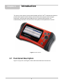
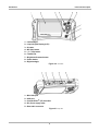
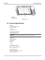
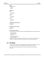
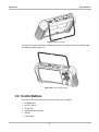
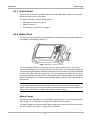
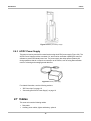
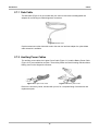
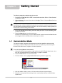
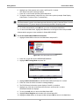
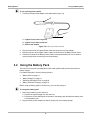
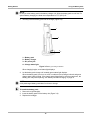
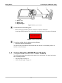
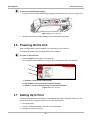
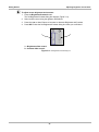
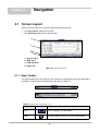
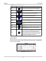
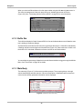
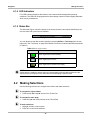
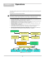
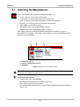
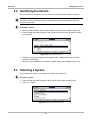
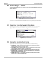
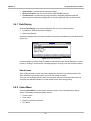
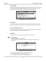
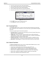
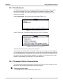
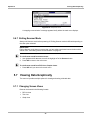
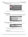
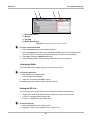
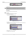
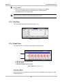
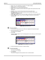
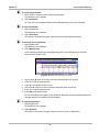
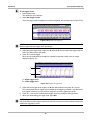
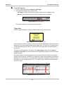
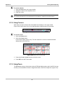
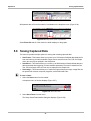
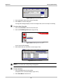
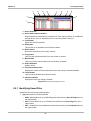
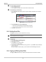
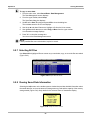
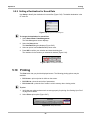
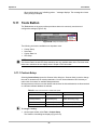
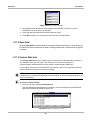
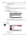
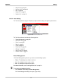
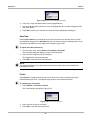
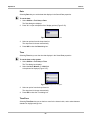
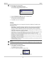
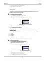
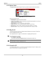
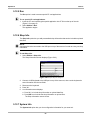
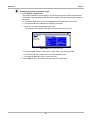
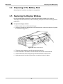

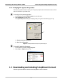
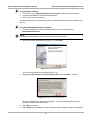
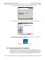
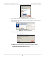
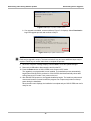


![VERUS PRO User Manual [3980kb PDF File] - Snap](http://vs1.manualzilla.com/store/data/005690474_1-9ff68923f14d7698ce72469cabae3990-150x150.png)