1
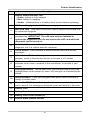
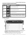
70
Legal Information
Trademarks
Snap-on, ShopStream Connect, SureTrack, and SOLUS Edge are trademarks
registered in the United States and other countries of Snap-on Incorporated. All
other marks are trademarks or registered trademarks of their respective
holders.
Copyright Information
© 2014 Snap-on Incorporated. All rights reserved.
Disclaimer of Warranties and Limitation of Liabilities
The information, specifications and illustrations in this manual are based on the
latest information available at the time of printing. While the authors have taken
due care in the preparation of this manual, nothing contained herein:
• Modifies or alters in any way the standard terms and conditions of the
purchase, lease, or rental agreement under the terms of which the
equipment to which this manual relates was acquired.
• Increases in any way the liability to the customer or to third parties.
Snap-on reserves the right to make changes at any time without notice.
Safety Information
IMPORTANT:
For your safety and the safety of others, before operating this diagnostic
tool, read, understand and follow all safety messages in the Important
Safety Instructions provided in your kit.
Contact Information (North America)
Websites
http://diagnostics.snapon.com
ShopStream Connect
http://diagnostics.snapon.com/ssc
User Manuals
http://diagnostics.snapon.com/usermanuals
Phone / E-mail - Technical Assistance
1-800-424-7226 / [email protected]
For technical assistance in all other markets, contact your selling agent.
ZEESC320A1 Rev. A 28-E-14 NA
Getting Started
Getting Started
Feature Identification
1
Feature Identification
Item
Description
1
Battery Status Indicator LED
• Green - battery is fully charged
• Red - battery is charging
• Amber - indicates there is a battery issue (correct before operating)
2
DC Power Supply Jack - AC/DC power supply connection
3
Mini USB Jack - USB cable connection used to transfer saved data files
to a personal computer
4
Micro secure digital (uSD) Card - Contains operating system
programming. IMPORTANT The uSD card must be installed to
operate the diagnostic tool. Do not remove the uSD card while the
diagnostic tool is turned on.
5
Data Cable Connector - Data cable connection used to connect the
diagnostic tool to a vehicle data link connector
6
Touch Screen - User interface to make onscreen menu and control
selections
7
N/X or Cancel Button - Push type button used to exit a menu or
program, return to the previous screen, or provide a “no” answer
8
Y/a or Accept Button - Push type button used to accept or confirm a
selection from a menu, advance to the next screen, or provide a “yes”
answer
9
Directional Button - Thumb pad rocker type buttons used to move the
highlight/focus on the screen up, down, left, and right, as indicated by the
arrows.
10
Shortcut Button - Push type programmable button used to perform a
variety of routine tasks.
11
Power (On/Off) Button - Push type button used to turn the diagnostic
tool on and off. For emergency shutdown, press and hold for 5 seconds.
12
Battery Pack
13
Battery Pack Cover
14
Battery Pack Cover Screws (2)
15
Built-in Stand (shown closed)
2
Basic Navigation
z
Battery Installation / Power Connection
1. Loosen the battery pack cover screws (located on back) and
remove the battery pack cover.
2. Align the locating tabs and install the battery pack.
3. Install the battery cover and tighten the screws.
DO NOT overtighten the battery cover screws.
The battery pack is supplied charged, however if needed
connect the AC/DC power supply to an appropriate power
source and into the “10-30V” DC power supply jack on top of the
diagnostic tool.
z
Turning the Diagnostic Tool On
Press and release the power button on the front of the
diagnostic tool to turn the diagnostic tool on.
i
NOTE:
The diagnostic tool automatically turns on when connected
to an external power source, such as the AC/DC power
supply or a vehicle data link connector (DLC).
Basic Navigation
Home Screen Icons
Name
Icon
Description
Scanner
Used to communicate with the electronic control
systems of a vehicle. Retrieve diagnostic trouble
codes (DTCs), view PID data and perform diagnostic
tests.
OBD-II/
EOBD
Access generic OBD-II/EOBD data and tests without
identifying the vehicle being tested.
Previous
Vehicles
& Data
Quickly reconfigure the diagnostic tool to a recently
tested vehicle and access saved data files.
Tools
Adjust diagnostic tool settings to your personal
preferences and perform other special functions.
3
Common Toolbar Control Icons
Common Toolbar Control Icons
Name
Icon
Description
Home
Returns to the Home screen.
Back
Returns to the previous screen.
Tools
Opens the Tools menu.
Save
Writes data from buffer memory to a file. The saved
“movie” file can be accessed for future reference by
selecting Previous Vehicles and Data > View Saved
Data.
Screen Layout
Diagnostic tool screens typically include three sections:
1) Title bar—displays information such as, active test, vehicle ID, current
time, power source indicator and vehicle communication indicator
2) Toolbar—contains test information and control icons
3) Main body—displays menus and test data. A vertical scroll bar
(right-hand edge) displays when there is additional data.
4
Basic Operation
Basic Operation
Scanner
Starting Scanner opens a menu list of vehicle manufacturers and
begins the process by identifying the vehicle being tested. After the
vehicle is identified, a vehicle system is selected and then a specific
test or function is selected to allow you to retrieve DTCs, view PID
data, perform diagnostic tests and view SureTrack™ information.
Scanner testing requires data cable connection to a vehicle DLC.
Depending on the vehicle, the supplied DA-4 data cable may be
used alone or may require optional adapters. Onscreen cable and
adapter connection instructions are provided during the Scanner
and OBD-II/EOBD vehicle identification process.
Scanner Demonstration Mode
Your diagnostic tool includes a demonstration mode that takes you
through a simulated vehicle identification process and allows you to
explore the capabilities of the Scanner function without actually
connecting to a vehicle.
IMPORTANT:
Do not connect the diagnostic tool to a vehicle while using
the Demonstration mode.
z
Starting the Demonstration
1. From the Home screen, select Scanner.
2. Select Demonstration from the manufacturer menu and follow
the menu choices to navigate to the desired system, test and/or
function.
5
SureTrack™
SureTrack™
SureTrack is a comprehensive source of expert repair knowledge
that will help you improve diagnostic accuracy and reduce repair
time.
SureTrack features:
• A Common Replaced Parts graph
• Tips and fixes obtained from actual repairs
• Up-to-the-minute information from vehicles currently being
serviced nationwide
i
z
NOTE:
To access SureTrack, you must turn the Wi-Fi radio on and
connect to a wireless network.
Wireless Network Setup / Basic Operation
1. From the Home screen, navigate to Tools > Settings >
Configure Wi-Fi.
2. Select the Wi-Fi Power icon from the toolbar to turn the Wi-Fi
radio on. The Wi-Fi power icon will change from a green check
mark a icon to red “X” mark icon indicating Wi-Fi radio is
currently on.
3. Choose your wireless network and select Connect.
SureTrack repair information can be accessed while reviewing
DTCs. As an example, select Scanner > Engine > Codes Menu >
Display Codes > Engine Trouble Code Information, then select a
DTC. If SureTrack information is available for the selected DTC, a
SureTrack results status message will display
(e.g. SureTrack - Results for P0102).
Below the results status message is the Common Replaced Parts
message (e.g. Common Replaced Parts - Based on 87 Repairs)
and the Common Replaced Parts graph icon ►. Select the icon to
toggle the Common Replaced Parts graph view on and off.
For detailed SureTrack operation instructions refer to your User
Manual. The User Manual is provided on the Documentation CD
included with your kit and is also available on our website. Website
addresses are listed in the front of this manual.
6
OBD-II/EOBD
OBD-II/EOBD
OBD-II/EOBD
OBD-II/EOBD allows you to access generic OBD-II/EOBD data and
tests without identifying the vehicle being tested.
Menu options are:
• OBD Direct - initiate a test session, check DLC location, or
manually select communication protocol
• OBD-II Health Check - quickly view or clear generic DTCs and
check readiness monitors
Previous Vehicles and Data
Previous Vehicles and Data allows you to save time by quickly
configuring the diagnostic tool to a recently tested vehicle and to
access saved data files.
Menu options are:
• Vehicle History - displays the last twenty-five vehicles tested
and available for selection
• View Saved Data - displays all saved data files, including
screen images
• Delete Saved Data - permanently erases saved data files from
memory
Tools
Tools allows you to change diagnostic tool settings to your
preferences and transfer saved data files to your PC.
Menu options are:
• Connect to PC - transfer saved data files to your PC using a
USB cable. Using the optional ShopStream Connect™
software, you can view, print and save data files to your PC and
also download software updates. ShopStream Connect is a free
online download. The ShopStream Connect website address is
listed in the front of this manual.
• Configure Shortcut Button - change the function of the
Shortcut button to one of five options
• Settings - change and adjust display and unit measurement
settings to your preferences
• System Information - displays software version, serial number
and system information
7


![VERUS PRO User Manual [3980kb PDF File] - Snap](http://vs1.manualzilla.com/store/data/005690474_1-9ff68923f14d7698ce72469cabae3990-150x150.png)