1
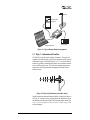
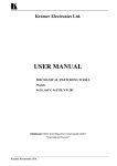
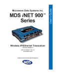
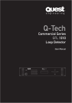
NR-100L/S
NR-100
REMOTE
VISA
HOST
VISA
RADIO
CHANNEL
HOST
SNA/SDLC
HOST
CONTROLLER
GAS
PUMPS
HOST
CONTROLLER
NR-100
REMOTE
PUBLIC OR
PRIVATE
WIDE AREA
NETWORK
POS
GAS STATION
ATM
SDLC
BANK BRANCH
MASTER STATION
NR-100
REMOTE
HOST
X.25
RESERVATIONS
TERMINAL
X.25
TRAVEL AGENCY
Remote Station Radio-Modem
Including instructions for TransIt Scope configuration software
MDS 05-3513A01, Rev. D
JUNE 2001
Installation and Operation Guide
TransItTM Data Radio Network
QUICK START GUIDE
Below are the basic steps for installing the NR-100 Remote Station. Detailed instructions are given in the
section titled “INSTALLATION” on page 6 of this manual.
1.
Install and connect the antenna system to the radio
• Use good quality, low loss coaxial cable. Keep the feedline as short as possible.
• Preset directional antennas in the direction of desired transmission/reception.
2. Apply DC power to the radio (10.5–16 Vdc @ 2.5A)
• Connect a DC power source to the NR-100’s power connector.(Negative ground only.)
• Observe proper polarity when connecting the DC cable. (Polarity marked on radio case.)
3. Review NR-100’s initial configuration
• Review vital parameters as listed on the packing slip. Use TransIt NMS (or TransIt Scope
software) to verify, and revise as necessary:
✓
✓
✓
✓
✓
TransIt network Cell Identification code and Remote Identification number
Radio-modem operating frequencies
Data protocols installed
Data protocol enabled
Desired user protocol
(See the NMS Network Administrator’s Handbook for details. P/N 05-3514A01)
4. Set the Configuration switches or internal jumpers on the NR-100 (if any)
• Set the configuration (CONFIG.) switches as required for the application. (See Table 3-3 on
page 24 for details.) Use a small instrument, such as a pencil point to move the switches to
the desired setting.
• Some models use internal jumpers (J12/J14) instead of configuration switches. See
page 24 for details.
5. Verify proper operation of the NR-100 as a TransIt radio-modem
• See Table 4-1 on page 25 for an explanation of the LED status indicators.
• Refine the antenna heading for maximum receive signal strength using the RSSI command
on an HHT. The HHT displays the RSSI in dBm.
6. Connect the user’s equipment to the NR-100’s DATA INTERFACE connector
• Use a DB-25 Male connector. Interface is RS-232/EIA-232 compatible.
(See Table 6-2 on page 31 for pin descriptions.)
7. Verify proper operation of the user’s equipment
• A properly configured system will work exactly as it would if the data terminal equipment
were communicating through a conventional wired system.
TABLE OF CONTENTS
1.0 INTRODUCTION ......................................................................... 1
1.1 About this Manual ............................................................................ 1
1.2 Related Radio Transceiver Manuals ................................................. 1
1.3 Related System Manuals ................................................................. 2
2.0 PRODUCT DESCRIPTION ......................................................... 2
2.1
2.2
2.3
2.4
2.5
NR-100’s Role in a TransIt Network ................................................. 2
Chassis Views .................................................................................. 3
Supported Protocols ........................................................................ 4
Model Number Codes ...................................................................... 4
Accessories ...................................................................................... 6
3.0 INSTALLATION ............................................................................ 6
3.1
3.2
3.3
3.4
3.5
Step 1—Antenna and Feedline ........................................................ 7
Step 2—Mounting the NR-100 ......................................................... 8
Step 3—Apply Primary Power .......................................................... 8
Step 4—Initial Operation & Checkout .............................................. 9
Step 5—Review of Operating Parameters ....................................... 9
Configuration Method #1:
Using TransIt NMS Software........................................................... 9
Power Output & Spread-Spectrum Network Address ................... 11
Cell ID, Remote ID Numbers and Response Delay ...................... 13
Configuration Method #2:
Using TransIt Scope Software....................................................... 14
3.6 Step 6—Check and Optimize the Master Station’s Signal ............. 22
3.7 Step 8—Connect Customer-Premises Equipment ......................... 23
3.8 Step 9—Arrange Data Clocking
(Not applicable to Ethernet models) ....................................................... 24
4.0 OPERATION .............................................................................. 25
4.1 LED Indicators ................................................................................ 25
Ethernet LED Indicators ............................................................... 25
5.0 TROUBLESHOOTING ............................................................... 26
5.1 LED Indicators ................................................................................ 26
6.0 TECHNICAL REFERENCE ....................................................... 27
6.1 NR-100 Specifications .................................................................... 27
6.2 Helical Filter Adjustment ................................................................ 27
6.3 Setting up the NMS Software to Configure the NR-100.................. 28
MDS 05-3513A01, Rev. D
NR-100 Installation and Operation Guide
i
6.4 dBm-Watts-Volts Conversion Chart ................................................ 30
6.5 Data Interface Connector ............................................................... 31
6.6 Ethernet Connector ........................................................................ 32
Copyright Notice
This Installation and Operation Guide and all software described herein are
protected by copyright. Copyright 2001, Microwave Data Systems Inc. All
rights reserved.
Operational Safety Notices
RF Exposure
The radio equipment described in this guide emits radio frequency energy.
Although the power level is low, the concentrated energy from a directional
antenna may pose a health hazard. Do not allow people to come in close proximity to the front of the antenna when the transmitter is operating. Refer to the
transceiver manual for further recommendations.
This manual is intended to guide a professional installer in installing, operating
and performing basic system maintenance on the described equipment.
Notice
While every reasonable effort has been made to ensure the accuracy of this
manual, product improvements may result in minor differences between the
manual and the product shipped to you. If you have additional questions or
need an exact specification for a product, please contact our Customer Service
Team using the information at the back of this guide. Microwave Data Systems
Inc. reserves its right to correct any errors and omissions in this document.
Updated information may also be available on our Web site at www.microwavedata.com.
Distress Beacon Warning
In the USA, the 406 to 406.1 MHz band is reserved for use by distress beacons.
Since some models of the product are capable of transmitting in this band, take
precautions to prevent the radio from transmitting between 406 to 406.1 MHz.
FCC Information
This equipment has been tested and found to comply with the limits for a Class
A digital device, pursuant to Part 15 of the FCC Rules. These limits are
designed to provide reasonable protection against harmful interference when
the equipment is operated in a commercial environment. This equipment generates, uses, and can radiate radio frequency energy and, if not installed and
used in accordance with the instruction manual, may cause harmful interference to radio communications. Operation of this equipment in a residential
area is likely to cause harmful interference in which case the user will be
required to correct the interference at his own expense.
Changes or modifications not expressly approved by the party responsible for
compliance could void the user’s authority to operate the equipment.
ii
NR-100 Installation and Operation Guide
MDS 05-3513A01, Rev. D
1.0 INTRODUCTION
1.1 About this Manual
This guide presents installation and operating instructions for the
NR-100 Network Remote Transceiver. It is one of two manuals shipped
with the product. This manual covers basic hardware installation and
configuration with the TransIt Network. The other manual is a
radio-specific guide with detailed coverage of RF path planning,
antenna & feedline selection, and radio programming topics.
Why two manuals? This approach is used because the NR-100 is a variation of a standard MDS transceiver (MDS x710, x810, etc.). Inside the
NR-100 case are two printed circuit boards sandwiched together—a
radio transceiver board, and a Main Controller Board (MCB).
This NR-100 manual focuses on the MCB functions, and deals only
briefly with radio topics. Installers and users of the equipment should
refer to the transceiver manual for complete radio information and specifications.
1.2 Related Radio Transceiver Manuals
Table 1-1 lists the radio manuals associated with the various sub-models
of the NR-100L (licensed narrowband) and NR-100S (spread spectrum)
transceiver. The “Configuration” column in the table refers to the value
of the seventh digit of the model number sticker found on the outside of
the unit. See “Model Number Codes” on page 4 for details on the configuration codes.
Table 1-1. Radio-Transceiver Manuals Supplied (Partial List)
Model
Band
Configuration
Radio Manual
Part No.
Description
NR-102L
200 MHz
All Units
05-3447A01
MDS 2710
Installation & Operation Guide
NR-104L
NR-109L
400 MHz
900 MHz
Standard (Digital)
05-3305A01
MDS 4710/9710
Installation & Operation Guide
NR-104L
NR-109L
400 MHz
900 MHz
Backward-Compatible
(Analog)
05-3316A01
MDS 4710B/9710B
Installation & Operation Guide
NR-104L
400 MHz
MPT1411
(United Kingdom)
05-3634A01
MDS 4710
Installation & Operation Guide
NR-109S
NR-124S
900 MHz
2.4 GHz
All Units
05-3301A01
MDS 9810/24810
Installation & Operation Guide
NOTE: Manuals for other frequency ranges and configurations will be
supplied as needed with each NR-100, but are not listed in this
abbreviated table.
05-3513A01, Rev. D
NR-100 Installation and Operation Guide
1
1.3 Related System Manuals
The NR-100 is designed to operate as part of a TransIt system that
includes a Master Station (NM-100 or NM-200) and Network Management Software (NMS). In addition to the manuals supplied with the
NR-100, the manuals listed in Table 1-2 should be available to the
installer and maintainer of the data communications system.
Table 1-2. Related Manuals
Part Number
05-3514A01
or
05-3684A01
05-3473A01
Description
NM-100 Master Station Guide
NM-200 Master Station Guide
Network Administrator’s Handbook
2.0 PRODUCT DESCRIPTION
2.1 NR-100’s Role in a TransIt Network
The NR-100 Remote station provides wireless data communication
between remote transactional equipment and a centralized “hub” or
Master station. (See Figure 2-1) Primary applications include Automatic Teller/Banking Machines (ATMs), Point-of-Sale (POS) terminals, lottery networks, and other “burst data” communications.
Transmission distances of 40 km or more can be achieved when the
radio link is operated over favorable (unobstructed) terrain. Figure 2-1
shows some common system arrangements.
NR-100
REMOTE
VISA
HOST
VISA
RADIO
CHANNEL
NM-100H
HOST
CONTROLLER
HOST
SNA/SDLC
NM-100H
HOST
CONTROLLER
GAS
PUMPS
NR-100
REMOTE
PUBLIC OR
PRIVATE
WIDE AREA
NETWORK
POS
GAS STATION
ATM
SDLC
BANK BRANCH
NM-100
MASTER STATION
HOST
X.25
NR-100
REMOTE
RESERVATIONS
TERMINAL
X.25
TRAVEL AGENCY
Figure 2-1. Typical System Using NR-100 Remote Stations
2
NR-100 Installation and Operation Guide
05-3513A01, Rev. D
NOTE: Some features described in this manual may not be available
on all units, based on the options purchased and the requirements for the region in which it will operate.
2.2 Chassis Views
Figure 2-2 and Figure 2-3 show the front and rear panels of a typical
NR-100 radio-modem.
All NR-100s are packaged in an similar cast enclosure. However,
Ethernet-equipped models will have an RJ-45 (modular) connector
instead of the configuration switch bank shown in Figure 2-2. Also,
Ethernet models will not have a DB-25 interface connector. The rear
panel on all NR-100s is identical.
Invisible place holder
Figure 2-2. NR-100 Remote Radio-Modem, Front View
(Left to Right: LEDS [top], Data Interface, NMS Port, Clock Switches)
Invisible place holder
Figure 2-3. NR-100 Remote Radio-Modem, Rear View
(Left to Right: Antenna and DC Power Connectors)
05-3513A01, Rev. D
NR-100 Installation and Operation Guide
3
2.3 Supported Protocols
The NR-100 supports many popular data protocols. This allows direct
connection to almost any type of data terminal equipment. The unit is
programmed at the factory to match the requirements of the customer
application. At the time of publication, the NR-100 can be shipped configured to support any one of the following protocols.
•
•
•
•
•
•
•
•
•
•
SDLC (IBM Synchronous Data Link Control)
X.25 and their related protocols such as X.28
(X.25 Asynchronous PAD) or QLLC (SDLC in X.25), etc.
TCP/IP (Transmission Control Protocol/Internet Protocol)
and related protocols such as SLIP (Serial Line Internet
Protocol) and PPP (Point to Point Protocol), etc.
VISA I and VISA II
Poll/Select (Burroughs Multipoint Terminal Protocol)
or similar
ALC/IPARS (Airline Link Control for flight reservations)
HDLC (High Level Data Link Control)
Bisync
Modbus
The NR-100 radio-modem is configured at the factory to a customer
specified profile that includes operating frequencies and protocol. Only
one of the available protocols is installed by the factory. This information and additional data are packaged with each NR-100 unit shipped.
SDLC is implemented by default, if no other protocol is specified when
the order was placed.
Refer to the TransIt Network Administrator’s Handbook (05-3473A01)
for additional discussion of data protocols and their configuration and
control in TransIt Network equipment.
2.4 Model Number Codes
The model number code printed on the end of the NR-100 enclosure
provides key information about how the unit was configured when it left
the factory. This information should agree with what is printed on the
packing slip. See Figure 2-4 for an explanation of the model number
codes for the NR-100L and Figure 2-5 for the NR-100S spread-spectrum radio-modem.
4
NR-100 Installation and Operation Guide
05-3513A01, Rev. D
THIS INFORMATION IS
SUBJECT TO CHANGE.
DO NOT USE FOR
PRODUCT ORDERING.
MODEM
A - Standard
B - Backward Compatible
C - 19200 bps
D - 3200 bps
M -MPT1411
BANDWIDTH
1 - 12.5 kHz
2 - 5 kHz
3 - 25 kHz
NR-100L
INPUT VOLTAGE
1 - 10.5–16.0 Vdc w/o Cable
2 - 10.5–16.0 Vdc w/Pigtailed Cable
A - 120/220 Vac w/Power Supply
AGENCY CERT.
N - None
F - FCC/IC
C - China CMII
G -MPT1411/CE
MTG BRACKETS
A - Standard
B - None
REGULATORY
N - N/A
C - CE Mark
1
N
RECEIVE FREQ.
A - 220–240 MHz
B - 330–355 MHz
C - 355–380 MHz
D - 380–400 MHz
E - 400–420 MHz
F - 406–430 MHz
G - 420–450 MHz
H - 450–480 MHz
I - 480–512 MHz
J - 800–860 MHz
K - 860–900 MHz
L - 900–960 MHz
M - 457.5–458.5 MHz
N - 463–464 MHz
P - 220–222 MHz
TRANSMIT FREQ.
1 - 220–240 MHz *
2 - 330–380 MHz *
3 - 380–400 MHz *
4 - 406–430 MHz
5 - 400–450 MHz
6 - 450–512 MHz
7 - 800–880 MHz *
8 - 880–960 MHz*
A -457.5-458.5 MHz
B -463-464 MHz
C -220-222 MHz
PROTOCOLS
A -SDLC (Default)
B -HDLC
C -X.25
D -X.28
E -SLIP
F - MODBUS
G -IP
* Not available with FCC/IC Certification
Figure 2-4. NR-100L “Licensed” Model Number Codes
As found on the product serial number and identification label
Invisible place holder
THIS INFORMATION IS
SUBJECT TO CHANGE.
DO NOT USE FOR
PRODUCT ORDERING.
NR-100S
AGENCY CERT.
F - FCC (900 MHz Models)
N - N/A
MOUNTING
BRACKETS
PROTOCOL
A - Standard
A -SDLC (Default)
B - None
B -HDLC
C -X.25
D -X.28
E -SLIP
F - MODBUS
G -IP
INPUT VOLTAGE
1 - 10.5–16.0 Vdc w/o Cable
2 - 10.5–16.0 Vdc w/Pigtailed Cable
A - 120/220 Vac w/Power Supply
N
FREQUENCY BAND
A - 900 MHz
B - 2.4 GHz
Figure 2-5. NR-100S “Spread-Spectrum” Model Number Codes
As found on the product serial number and identification label
05-3513A01, Rev. D
NR-100 Installation and Operation Guide
5
2.5 Accessories
The NR-100 can be used with one or more of the accessories listed in
Table 2-1. Some items from the list may be supplied with the NR-100.
Please contact the factory for ordering information.
Table 2-1. TransIt NR-100 Accessories
Accessory
Description
Part No.
Hand-Held Terminal
(HHT) Kit
Terminal that plugs into the NR-100 for
radio configuration & diagnostics.
Includes carrying case, booklet and
cable set.
02-1501A01
120/220 Vac
Power Supply Module
120/220 Vac to 12 Vdc power supply.
28-2334A07
AC Cord Set
2-wire line cord to connect to the
28-2334A07 power supply module
above. (North American plug)
19-1065A06
DC Power Connector
Adapter
Coverts the two-pin chassis receptacle
to a barrel-type jack for use with the
28-2334A07 AC supply.
28-2334A07
DC Power Cable
Two-wire cable assembly, one meter
long, with pigtails.
03-1846A02
RJ-11 to DB-9 Adapter
Used to connect a PC to the NR-100’s
NMS Port. RJ-11 to RJ-11 (Cable not
included.)
73-2434A02
NMS Software
Provides diagnostics & setup of the
NR-100’s radio functions.
(Windows-based PC required.)
03-3517A01
3.0 INSTALLATION
There are four key requirements for a successful installation of an
NR-100 Network Remote—adequate and stable primary power, a good
antenna system, the correct data connections between the NR-100 and
the user equipment, and the correct TransIt Network configuration.
A successful installation is one in which the NR-100 Remote station is
able to reliably communicate with the desired Master station.
The following sections describe the basic steps to install the NR-100. In
most cases, these steps alone are sufficient to complete the installation.
If you need more information on a radio topic, refer to the transceiver
manual shipped with the NR-100.
Figure 3-1 shows a typical hardware installation of an NR-100.
6
NR-100 Installation and Operation Guide
05-3513A01, Rev. D
Invisible place holder
Antenna
Customer Data
Equipment
NR-100
Windows-based PC
Power Supply
Figure 3-1. Typical Remote Station Arrangement
3.1 Step 1—Antenna and Feedline
The NR-100 can be used with a number of antennas. The exact style
depends on the radio frequency used by the equipment and the required
transmission range. A directional Yagi (Figure 3-2) or corner reflector
antenna is generally recommended at remote sites to minimize interference to and from other users. The Transceiver manual contains more
information on selecting antennas and appropriate feedlines for the
antenna system.
Invisible place holder
Figure 3-2. Typical Yagi Antenna (mounted to mast)
Install the station antenna and antenna feedline. Connect the feedline to
the Type “N” connector on the rear panel of the NR-100 and aim the station antenna in the direction of the TransIt Network Master station. See
Step 6—Check and Optimize the Master Station’s Signal on page 22 for
more information.
05-3513A01, Rev. D
NR-100 Installation and Operation Guide
7
3.2 Step 2—Mounting the NR-100
a. Mount the NR-100 to a stable surface using the brackets supplied by the factory. Figure 3-3 shows the mounting dimensions
of the NR-100 case. The unit can be mounted in any position.
AA
A
A
A
A
AA
AAA
A
A
AAA
1 .7 5 "
4 .4 4 C M
2.75"
70 mm
Alternate
Position
7.25"
184 mm
Invisible place holder
6.63"
168 mm
8.5"
216 mm
5.625"
143 mm
2.0"
50 mm
2.25"
57 mm
AAAAAAAAA
Figure 3-3. NR-100 Mounting Dimensions
3.3 Step 3—Apply Primary Power
a. Measure the primary power for the radio and connect it to the
rear panel PWR connector. The unit can be operated from any
well-filtered 10.5 to 16 Vdc power source capable of providing
at least 2.5 amperes of continuous current. The red wire on the
power cable is the positive lead; the black is negative.
NOTE: The NR-100 is designed for use only in negative ground
systems.
A check of the supply voltage is not necessary if the factory AC
power supply is used.
b. Apply power to the NR-100. The PORT LED should be on and
the STATUS LED should be flashing indicating the NR-100’s
electronic circuitry is functioning normally. (See Table 4-1 for
LED functions.)
8
NR-100 Installation and Operation Guide
05-3513A01, Rev. D
3.4 Step 4—Initial Operation & Checkout
a. Check to see if the LINK LED is on. If it is, the NR-100 is receiving a valid signal from the TransIt Master station. If the LED is
on you can skip to Step 6—Check and Optimize the Master Station’s Signal on page 22. If the LINK LED is off, continue to the
next step in this procedure.
3.5 Step 5—Review of Operating Parameters
Before installation is complete, it is necessary to verify that the NR-100
radio-modem parameters are set as directed by the Network Administrator. Two methods may be used to accomplish this, and each is
described below:
• Method #1—TransIt NMS Software. All TransIt systems are
supplied with TransIt NMS software (Part No. 03-3517A01).
This software allows for a complete review and configuration of
master station (NM-200) and NR-100 settings. This method is
discussed first in the sections below. For complete details on the
NMS program, refer to the Network Administrator’s Handbook
(Part No. 05-3473A01).
• Method #2—Optional TransIt “Scope” Software (formerly
called TinyNMS). TransIt Scope software is included on the
TransIt CD (Part No. 06-3618A01) and is specifically tailored
for the NR-100 radio-modem. Many installers find this smaller
package easier to use because it deals strictly with NR-100 settings and allows a large number of remote radios to be
reviewed/configured in a short time.
Instructions for using TransIt Scope begin on Page 14 of this
manual. If you plan to use this software for NR-100 configuration you may proceed directly to that section now.
Configuration Method #1:
Using TransIt NMS Software
NOTE: The NMS computer needs to have a test entry in the equipment
list that will be used for all installations. See Setting up the
NMS Software to Configure the NR-100 in the Field on page
28 for further information. The following steps assume this has
been set up in advance.
Most of the steps that follow apply to all models of the NR-100.
Steps that apply only to the NR-109S and NR-124S are marked.
a. Connect a Windows PC with the TransIt NMS software installed
to the NMS Port of the NR-100 to review the radio operating
parameters. (See Figure 3-4.)
05-3513A01, Rev. D
NR-100 Installation and Operation Guide
9
Invisible place holder
NMS PORT
(RJ-11 CONNECTOR)
WINDOWS PC RUNNING
TRANSIT NMS SOFTWARE
Figure 3-4. PC with NMS Software Connected to the NR-100
b. Launch the NMS software.
c. Click on the Monitoring icon to refresh the display. The icon of a
remote transceiver should show up below the bar in the primary/master station equipment section. The top portion will be
green to indicate the NMS is communicating with the NR-100. It
is normal for the bottom half to be colored red. Note: The number below the radio icon is the Cell ID of the NR-100.
NR-100
If the icon does not show up, then click on the Monitoring icon
again; it may take several seconds for the NMS software to
establish communication with the NR-100 radio-modem.
d. Click on the NR-100 icon in the Monitoring window. The Element
Management window will be displayed similar to Figure 3-5.
CONFIGURE:
• Cell ID
• Remote ID
CONFIGURE:
• TX/RX Frequency
• Power Output
• SS Address
MEASURE:
• RSSI
ACTIVE
PROTOCOL
Figure 3-5. Element Management Window
In Configuration Mode
10
NR-100 Installation and Operation Guide
05-3513A01, Rev. D
e. Click on the Configuration (book) icon to enter the configuration
mode.
Power Output & Spread-Spectrum Network Address
a. Click on the telephone and modem icon to bring up the
Radio-Modem and Cell Configuration window as seen in Figure 3-6.
The Parameters tab will display ten unit parameters. It may take a
few seconds before all of the parameter information is received
from the NR-100.
b. Observe the power output level to verify it is as assigned by the
Network Administrator. See Table 3-1 for power output ranges
and defaults.
Figure 3-6. Radio-Modem and Cell Configuration Window
Parameters Tab Active
Table 3-1. Power Output Range
Radio Model
Default Setting
Range
NR-100L
37 dBm
10–37 dBm
NR-109S
30 dBm
20–30 dBm
NR-124S
30 dBm
10–30 dBm
NOTE: Displayed frequency information is not relevant for spread
spectrum models (NR-109S and NR-124S).
c. If any of the parameters are not as assigned, click on the Configuration tab to change to the data entry pane as seen in Figure 3-7.
05-3513A01, Rev. D
NR-100 Installation and Operation Guide
11
Invisible place holder
Figure 3-7. Radio-Modem and Cell Configuration Window
Configuration Tab Active
d. Enter the correct values and click on the Send button. (Do not
change the frequency on NR-109S and NR-124S models.)
Step only for
NR-109S and
NR-124S Models
e. Click on the Terminal tab. The terminal mode will be used to set
the spread-spectrum network address. A terminal screen will
appear similar to that in Figure 3-8.
Invisible place holder
Figure 3-8. Radio-Modem and Cell Configuration Window
Terminal Mode Active
Step only for
NR-109S and
NR-124S Models
12
f. Type in the command ADDR and press the RETURN key. The
radio-modem will respond with the current unit address.
NR-100 Installation and Operation Guide
05-3513A01, Rev. D
Step only for
NR-109S and
NR-124S Models
g. If the displayed address is not as assigned by the Network
Administrator, type in ADDR + space + address number. Then
press RETURN . If the NR-100 accepts the number, the response
PROGRAMMED OK will show up on the screen.
h. Click on the Parameters tab and verify that the parameters you
entered are properly shown in the window.
i. Click on the Close button to return to the Element Configuration
window.
Cell ID, Remote ID Numbers and Response Delay
a. Click on the radio icon to bring up the TransIt Protocol Parameters
window for the NR-100.
Figure 3-9. TransIt Protocol Parameters Settings Window
Table 3-2. Basic Network Configuration Commands
Parameter
Default
Range
Cell Identifier
1
1–254
Remote Identifier
99
1–249
Response Delay
0 ms
0–255 (ms)
Maximum Transmission Unit
512
512 (bytes)
b. Enter the Cell ID and Remote ID as assigned by the Network
Administrator.
c. Set the Response Delay to zero milliseconds (0 ms) or as assigned
by the Network Administrator.
d. Set the MTU (Maximum Transmission Unit) to 512.
05-3513A01, Rev. D
NR-100 Installation and Operation Guide
13
NOTE: Do not change any other parameters other unless instructed by
the Network Administrator.
e. Click the Send button to apply the settings to the NR-100.
f. Close the window by clicking on the Close button and return to
the Element Configuration window.
g. Click the Tools (wrench) icon. A pop-up list of options will
appear as shown in Figure 3-10.
Figure 3-10. Tools Pop-up Menu
h. Select the Save Configuration item. This action will save the new
configuration parameters in the NR-100.
This completes the review and setting of the basic configuration with
NMS.
Configuration Method #2:
Using TransIt Scope Software
TransIt Scope software simplifies the deployment of large networks by
providing a simple configuration tool for setting the minimal number of
parameters required to commission a remote radio. This tool eliminates
the need for a full knowledge of the NMS capabilities and also prevents
access to critical parameters, which, if improperly set, could compromise the operation of the entire network. The Scope program is included
on the TransIt CD (Part No. 06-3618A01) provided with your radio
system.
Scope allows configuration of two key parameters—Cell ID and
Remote ID. It also allows the minimum set of radio-modem parameters
to be accessed—Frequency (narrowband models only), RF Transmit
Power, and Address (spread spectrum models only). In addition, the
software displays an RSSI “gauge” that is useful for aiming the station
antenna for maximum received signal from the Master site. Finally, a
“Ping” function is provided, so that an installer can verify the link
quality of an installation.
14
NR-100 Installation and Operation Guide
05-3513A01, Rev. D
When all of the Scope functions have been exercised and communication has been established between the remote and the master station, the
NR-100 installer’s job is considered complete. The Network Administrator can proceed to download the appropriate configuration files for
the protocol using the full TransIt NMS package.
Installing TransIt
Scope
The steps below describe the installation of TransIt Scope software from
the TransIt CD. The software can be used with any Windows-based PC,
but is most commonly installed on a laptop-style computer, as this
allows portability when visiting multiple remote sites.
a. Insert the TransIt CD and locate the Scope software files (see
Figure 3-11).
Invisible place holder
Figure 3-11. Transit Scope Files on TransIt CD
b. Double-click on the setup.exe file. The Welcome screen
(Figure 3-12) will appear. (Note: If an error message appears
stating that some files can’t be added, simply click the Ignore button to proceed—this error can occur on Windows NT computers,
and does not apply to TransIt Scope files.)
05-3513A01, Rev. D
NR-100 Installation and Operation Guide
15
Invisible place holder
Figure 3-12. TransIt Scope Welcome Screen
c. Click the OK button on the Welcome screen to prepare the program for installation. When this is done, the screen shown in
Figure 3-13 appears, allowing you to install the software in the
desired directory of your computer (typically C:). If you wish to
select a different location from the one shown, use the Change
Directory button.
Click the large button near the top left of the Setup screen to
begin the software installation.
Invisible place holder
Figure 3-13. Directory Selection Screen
d. The Program Group screen appears next (Figure 3-14), allowing
you to select the group in which the software will be installed
(typically Transit SCOPE). If you wish to select a group other than
the one highlighted, select it from the list of Existing Groups.
When you are ready to proceed, press the Continue button.
16
NR-100 Installation and Operation Guide
05-3513A01, Rev. D
Invisible place holder
Figure 3-14. Program Group Screen
e. It will take a few moments for the Scope software to be fully
installed. When the installation is complete, the screen shown in
Figure 3-15 appears.
Invisible place holder
Figure 3-15. Installation Complete Screen
Using TransIt Scope
Software with the
NR-100
With TransIt Scope properly installed as described above, you are now
ready to use the software. Most program functions described here apply
to all NR-100 models. Functions pertaining only to the NR-100S or
NR-100L are so marked.
a. Connect the PC with TransIt Scope software installed to the NMS
Port of the NR-100 (Figure 3-16).
05-3513A01, Rev. D
NR-100 Installation and Operation Guide
17
Invisible place holder
NMS PORT
(RJ-11 CONNECTOR)
WINDOWS PC RUNNING
TRANSIT SCOPE SOFTWARE
Figure 3-16. PC with Scope Software Connected to the NR-100
b. Launch the Scope software. If the NR-100’s serial port has
already been configured, the Radio Status screen (Figure 3-17)
will appear. This screen shows basic information about the radio
you are connected to, and allows changes to certain parameters.
Invisible place holder
Figure 3-17. Radio Status Screen
If the serial port has not been properly configured, the software will
not be able to communicate with the NR-100. It will attempt to connect, displaying the message Getting information, and will then issue a
message Equipment does not respond. In these cases, select Settings
from the top menu bar and configure the serial port with the correct
parameters.
The Settings screen is shown in Figure 3-18. This is where you can
specify the correct Port, Baudrate and other connection parameters
for the NR-100.
18
NR-100 Installation and Operation Guide
05-3513A01, Rev. D
The default settings for the serial port are shown in the figure. While
these settings will work for most remote stations, minor changes
may be required for some systems. Check with your Network
Administrator to obtain the correct parameters for your remote(s).
Pay particular attention to the Port and Baudrate settings as these are
critical for proper connection to the NR-100.
The screen also allows for frequency/channel settings (right side) to
be specified. Again, check with your Network Administrator for the
appropriate entries.
Invisible place holder
Figure 3-18. Settings Screen
With a successful connection to the NR-100, the radio’s key parameters will be displayed on the Information Screen (Figure 3-19). The
screen shown below is for a narrowband (licensed) NR-100. The
display for a spread spectrum radio will be slightly different.
A spread spectrum screen includes two additional parameters—Addr
(address) and Mode (Master or Remote). Frequencies are displayed
on a spread spectrum radio but they cannot be selected or changed
by the user.
05-3513A01, Rev. D
NR-100 Installation and Operation Guide
19
Invisible place holder
Figure 3-19. Information Screen, Narrowband Radio
(Spread Spectrum Display Similar)
The Information screen in Figure 3-19 shows that:
• Local communication with the NR-100 is working.
• It is a narrowband (licensed) radio, thus the TX and RX frequencies are selectable and may be modified.
• The Radiolink display shows Online, indicating there is communication with the master station.
NOTE: A password is required to make changes to the NR-100 parameters described in the next step. The default password is
TRANSIT, but it is recommended that this password be changed
to a custom entry using the Change Password command at the
top menu bar.
Make a note of the password you choose and keep it in a safe
place. If the password is forgotten, it will be necessary to
completely re-install the TransIt Scope program.
c. NR-100 parameters that can be changed with TransIt Scope are
shown at the right-hand side of the Information screen. If
changes are required, click into the appropriate box and type the
new information. Your Network Administrator can furnish the
required data for these fields. Click the Send button when done.
20
NR-100 Installation and Operation Guide
05-3513A01, Rev. D
A summary of the user-changeable parameters follows:
•
•
•
•
•
•
•
Cell (1-254)—The
Cell ID of the NR-100 remote
Remote (1-249)—Remote radio’s ID number
TX Frequency (MHz)*—Transmit frequency
RX Frequency (MHz)*—Receive frequency
Power (dBm)—Transmitter output power
Addr (1-65000)**—The NR-100’s system address
Frequency Set*—Refers to the channel number(s) previously
selected in the Settings screen (see Figure 3-18).
* Narrowband radios only
** Spread spectrum radios only
A Received Signal Strength Indication (RSSI) is also shown on the
Information screen. The less negative the RSSI, the stronger the
incoming signal from the master station, thus a reading of -70 dBm
represents a stronger signal than -80 dBm. When installing the
remote antenna, it should be oriented for the strongest possible
incoming signal. More details are given in section 3.6 on page 22.
d. After the NR-100 settings have been set and/or verified, the Ping
function can be used to check over-the-air communications
integrity with the master station. To begin the test, select Ping
from the top menu bar. A screen similar to the one shown in
Figure 3-20 will appear.
Invisible place holder
Figure 3-20. Ping Test Screen
e. Select the number of Iterations. We recommended using at least
the default value of 16 iterations.
05-3513A01, Rev. D
NR-100 Installation and Operation Guide
21
f. Select the Packet Size (number of bytes) in the data portion of the
window. We recommend using the largest transaction size
expected, or a number between 100 and 256.
g. Click the Start button to initiate the Ping test.
h. Verify that the average number of seconds in the response time
(right column in the upper portion of screen) shows an appropriate number. On a typical 19,200 kbps link using a 256 byte message size you should see an average response time around 600
ms. The Error Rate field should be at (or near) zero in an optimum
installation.
3.6 Step 6—Check and Optimize the Master
Station’s Signal
Use either TransIt NMS or Scope software to check the incoming
received signal strength level of the Master station. The level is
displayed in –dBm and is refreshed every 20 seconds. The Network Administrator will advise you of the minimum acceptable
signal level. If it is lower than recommended, adjusting the
antenna direction may improve it.
Typical minimum acceptable values are between –70 and –80
dBm. Rotation of the station antenna to maximize the Master station’s signal is not likely to affect system reliability when the
signal level is stronger than –50 dBm.
NOTES: The less negative the RSSI value, the stronger the signal.
Therefore, a –70 dBm signal is stronger than a –80 dBm
signal.
The radio-modem’s RSSI circuitry is unable to accurately
display incoming signal levels stronger than –50 dBm.
The following steps describe RSSI measurement using the Transit NMS
package. Instructions for using Scope software are given in the text
accompanying Figure 3-19.
a. Click on the telephone and modem icon to bring up the
Radio-Modem and Cell Configuration window as seen in Figure 3-21.
22
NR-100 Installation and Operation Guide
05-3513A01, Rev. D
Invisible place holder
Figure 3-21. Radio-Modem and Cell Configuration Window
Received Signal Strength Indication Highlighted
b. Make a note of the received signal strength. If it is within the
range as recommended by the Network Administrator no action
is required. If the value is less than desired, rotate the antenna a
few degrees and observe the change in signal strength. Continue
this process until the strongest possible signal is obtained.
c. The testing and configuration of the radio-modem functions is
now complete and connection of the customer-premises equipment (CPE) may be made.
3.7 Step 8—Connect Customer-Premises
Equipment
CAUTION
RADIO FREQUENCY
INTERFERENCE
POTENTIAL
05-3513A01, Rev. D
a. Connect the customer-premises equipment to the NR-100 DATA
INTERFACE connector (or ETHERNET connector for models so
equipped). The NR-100 serves as a DCE device (default). See
the complete list of pin functions provided in Table 6-2 on
page 31 (standard models) or section 6.6 on page 32 (Ethernet
models).
Shielded data interface cables must be used with the NR-100L/S to
meet U.S.A.’s FCC Part 15, Class A limits.
NR-100 Installation and Operation Guide
23
3.8 Step 9—Arrange Data Clocking
(Not applicable to Ethernet models)
Review the NR-100 interface clocking arrangement. The default is for
the radio to act like a Data Communications Equipment (DCE). If the
equipment attached to the NR-100L/S operates as Data Terminating
Equipment (DTE), then no changes are needed.
NOTE: Depending on the date of manufacture, the NR-100 you have
may contain configuration switches on the front panel (early
models) or internal jumpers (late models) for setting the
clocking arrangement. The jumpers are located on the PC
board, directly behind the NMS connector. Refer to Table 3-3
which lists settings for both switches and jumpers.
Figure 3-22 shows the location of the configuration switches, if present.
If no switches are present, internal jumpers (J12, J14) are used to configure the radio’s clocking arrangement. Refer to Table 3-3 for the
default switch/jumper settings and alternate arrangements.
Invisible place holder
Configuration Switches
ON
OFF
1
2
3
TD
See Table 3-3 for details.
Defaults are shown above.
AN
TE
NN
A
IN
RD
Figure 3-22. Location of Configuration Switches (if present)
Late models use internal jumpers instead of switches—See note above
Table 3-3. Switch/Jumper Settings for Data Clocking
Connected
Equipment
NR-100L/S
Radio-Modem
Config. Switches
(if present)
Int’l Jumpers
(if no switches)
Config.
Clock
Source
Config.
Clock
Source
SW1
SW2
SW3
J12
J14
DTE
External
DCE
Internal
ON
OFF
OFF
OFF*
ON**
DTE
Internal
DCE
Split
ON
OFF
OFF
OFF*
ON**
DTE
Internal
DCE
Looped
ON
OFF
OFF
OFF*
ON**
DCE
Internal
DCE
Ext’l
OFF
ON
OFF
ON**
OFF*
* Jumper plug not present
** Jumper plug present
24
NR-100 Installation and Operation Guide
05-3513A01, Rev. D
4.0 OPERATION
Once the NR-100 is able to communicate with the TransIt master station
over the air, the Network Administrator can remotely take control
through the Network Management System (NMS) software and finalize
the radio-modem configuration.
In-service operation of the NR-100 is completely automatic. Once the
unit has been properly installed and configured, operator actions are
limited to observing the front panel LEDs for proper operation.
4.1 LED Indicators
Table 4-1 describes the function of the LED indicators on the front panel
of the NR-100.
STATUS LINK
PORT ALARM
Table 4-1. NR-100 LED Status Indicators
LED Name
Description
STATUS
• Flashing—System is working properly.
• Off—No primary power to the NR-100.
• Continuous—Main Controller Board (MCB) failure.
LINK
• Continuous—A link has been established with the Master station.
• Off—There is no link with the Master station.
PORT
• Continuous—Customer port is on and active.
• Off—Customer port is inactive.
ALARM
Indication of a radio problem. (May indicate buffer overflow or lost data
packets.)
Ethernet LED Indicators
On Ethernet-equipped radios, two additional LEDs are present on the
front panel—DATA and OK. The LEDs are located directly above the
ETHERNET connector and are explained in Table 4-2.
Table 4-2. Ethernet LEDs (on models so equipped)
LED Name
DATA
Description
• Green—Receiving data into connector.
• Red—Transmitting data out of connector
OK
05-3513A01, Rev. D
• Green—A valid link is established.
• Red—Buffer error alarm.
NR-100 Installation and Operation Guide
25
5.0 TROUBLESHOOTING
Troubleshooting a TransIt system not difficult, but it requires a logical
approach. It is best to begin troubleshooting at the master station, as the
rest of the system depends heavily on the master for proper control and
operation. If the master station has problems, the entire network can be
compromised.
It is good practice to start by checking the simple things. For proper
operation, all units in the data network must meet these basic requirements:
• Adequate and stable primary power. The remote radio contains
an internal self-resetting fuse. To reset, remove and re-apply
power.
• Secure cable connections (RF, data and power)
• An efficient and properly aligned antenna system with a good
received signal strength (at least –90 dBm). It is possible for a
system to operate with weaker signals, but reliability will be
degraded.
• Proper programming of the NR-100’s operating parameters.
(See Section 3.5, Step 5—Review of Operating
Parameters (beginning on page 9)
• The correct interface between the NR-100 and the connected
data equipment (correct cable wiring, proper data format, timing, etc.) Refer to Table 6-2 for a chart of NR-100 interface connections.
5.1 LED Indicators
The LED status indicators are an important troubleshooting tool and
should be checked whenever a problem is suspected. Table 4-1 on
page 25 describes the function of each status LED.
26
NR-100 Installation and Operation Guide
05-3513A01, Rev. D
6.0 TECHNICAL REFERENCE
6.1 NR-100 Specifications
The specifications listed here are generic to all models. See associated
radio transceiver manual for frequency-specific details.
DATA INTERFACE PORT
Connector:
DB-25 Female
Signaling Standard:
EIA-232
Data Interface Rates:
Protocol Dependent; 19.2 kbps Maximum
Protocol:
Software based; As selected by user
NMS PORT
Connector:
RJ-11
Signaling Standard:
EIA-232
Protocol:
Proprietary (MDS)
I/O Devices:
Hand-Held Terminal; PC with NMS software
PRIMARY POWER
Voltage:
13.6 Vdc Nominal (10.5 to 16.0 Vdc)
Negative Ground
TX Supply Current:
NR-100L—2.0 Amperes @ 5 watts RF output
NR-100S—1.0 Amperes @ 1 watt RF output
RX Supply Current:
205 mA (nominal)
Fuse:
4 Ampere Polyfuse, Self-Resetting, Internal
(Remove primary power to reset.)
Reverse Polarity Protection:
Diode across primary input
ENVIRONMENTAL
Humidity:
95% at 40 degrees C (104 degrees F)
Non-condensing
Temperature Range:
–30 to +60 degrees C
(22 to +140 degrees F)
Weight:
1.27 kg (2.8 Lbs.)
Dimensions:
5.08 x 14.29 x 18.4 cm (H x W x D)
(2.0 x 5.62 x 7.25 inches)
Case:
Die-cast aluminum
6.2 Helical Filter Adjustment
On some models, a significant change in operating frequency may
require adjustment of the helical filters on the radio board to maintain
proper receive sensitivity. Refer to the transceiver manual shipped with
the NR-100 for alignment details.
05-3513A01, Rev. D
NR-100 Installation and Operation Guide
27
6.3 Setting up the NMS Software to Configure the
NR-100 in the Field
Prior to installing an NR-100 it is advisable to prepare a computer, usually a laptop, for service as a test and configuration tool.
1. Plug in the computer with the NMS software into the NMS port on
an NR-100 radio-modem. Use the factory-supplied cable set.
2. Launch the NMS software.
3. Click on the Communications and Configuration icon in the Monitoring
window to bring up the Interface Configuration Window.
Configure the screen as shown in Figure 6-1 below.
A. Select “RS-232 Local”.
B. Select Communications port
which is connected to the NR-100’s
NMS Port.
C. Set “Cell” and “Remote” to “ALL”.
Figure 6-1. Interface Configuration Window
4. Click the Save and Exit button to return to the Monitoring window.
28
NR-100 Installation and Operation Guide
05-3513A01, Rev. D
5. Click on the Network Address (Cell) Configuration icon. The configuration table will appear. Figure 6-2 contains recommended field values.
1
RS-232
Test
Figure 6-2. Network Configuration Window (with Example Info)
Contact and Telephone fields are out of view to the right.
6. Set up one entry to communicate with the NR-100 using RS-232, a
CELL# of 1 and a SITE name of Test.
7. Press the down arrow key or click outside and below the table. If this
is not done, the changes will not be saved. You need to scroll outside
the modified row for the changes to take effect.
8. Click the Save and Exit button. The NMS software is now ready for
service in reviewing and configuring NR-100 operating parameters.
05-3513A01, Rev. D
NR-100 Installation and Operation Guide
29
6.4 dBm-Watts-Volts Conversion Chart
Table 6-1 is provided as a convenience for determining the equivalent
wattage or voltage of an RF power expressed in dBm.
Table 6-1. dBm-Watts-Volts Conversion—for 50 Ohm Systems
30
dBm V
Po
dBm V
Po
dBm mV
+53
+50
+49
+48
+47
+46
+45
+44
+43
+42
+41
+40
+39
+38
+37
+36
+35
+34
+33
+32
+31
+30
+29
+28
+27
+26
+25
+24
+23
+22
+21
+20
+19
+18
+17
+16
+15
+14
+13
+12
+11
+10
+9
+8
+7
+6
+5
+4
+3
+2
+1
200W
100W
80W
64W
50W
40W
32W
25W
20W
16W
12.5W
10W
8W
6.4W
5W
4W
3.2W
2.5W
2W
1.6W
1.25W
1.0W
800mW
640mW
500mW
400mW
320mW
250mW
200mW
160mW
125mW
100mW
80mW
64mW
50mW
40mW
32mW
25mW
20mW
16mW
12.5mW
10mW
8mW
6.4mW
5mW
4mW
3.2mW
2.5mW
2.0mW
1.6mW
1.25mW
0
-1
-2
-3
-4
-5
-6
-7
-8
-9
-10
-11
-12
-13
-14
-15
-16
1.0mW
.80mW
.64mW
.50mW
.40mW
.32mW
.25mW
.20mW
.16mW
.125mW
.10mW
-49
-50
-51
-52
-53
-54
-55
-56
-57
-58
-59
-60
-61
-62
-63
-64
100.0
70.7
64.0
58.0
50.0
44.5
40.0
32.5
32.0
28.0
26.2
22.5
20.0
18.0
16.0
14.1
12.5
11.5
10.0
9.0
8.0
7.10
6.40
5.80
5.00
4.45
4.00
3.55
3.20
2.80
2.52
2.25
2.00
1.80
1.60
1.41
1.25
1.15
1.00
.90
.80
.71
.64
.58
.500
.445
.400
.355
.320
.280
.252
.225
.200
.180
.160
.141
.125
.115
.100
.090
.080
.071
.064
.058
.050
.045
.040
.0355
dBm µV
dBm mV
-17
-18
-19
-20
-21
-22
-23
-24
-25
-26
-27
-28
-29
-30
-31
-32
-33
-34
-35
-36
-37
-38
-39
-40
-41
-42
-43
-44
-45
-46
-47
-48
31.5
28.5
25.1
22.5
20.0
17.9
15.9
14.1
12.8
11.5
10.0
8.9
8.0
7.1
6.25
5.8
5.0
4.5
4.0
3.5
3.2
2.85
2.5
2.25
2.0
1.8
1.6
1.4
1.25
1.18
1.00
0.90
Po
.01mW
.001mW
.1µW
NR-100 Installation and Operation Guide
-65
-66
-67
-68
-69
-70
-71
-72
-73
-74
-75
-76
-77
-78
-79
-80
-81
-82
-83
-84
-85
-86
-87
-88
-89
-90
-91
-92
-93
-94
-95
-96
-97
Po
0.80
0.71 .01µW
0.64
0.57
0.50
0.45
0.40
0.351
0.32
0.286
0.251
0.225 .001µW
0.200
0.180
0.160
0.141
128
115
100
90
80
71
65
58
50
45
40
35
32
29
25
22.5
20.0
18.0
16.0
11.1
12.9
11.5
10.0
9.0
8.0
7.1
6.1
5.75
5.0
4.5
4.0
3.51
3.2
Po
.1nW
.01nW
.001nW
dBm µV
-98
-99
-100
-101
-102
-103
-104
-105
-106
2.9
2.51
2.25
2.0
1.8
1.6
1.41
1.27
1.18
dBm nV
-107
-108
-109
-110
-111
-112
-113
-114
-115
-116
-117
-118
-119
-120
-121
-122
-123
-124
-125
-126
-127
-128
-129
-130
-131
-132
-133
-134
-135
-136
-137
-138
-139
-140
1000
900
800
710
640
580
500
450
400
355
325
285
251
225
200
180
160
141
128
117
100
90
80
71
61
58
50
45
40
35
33
29
25
23
Po
.1pW
Po
.01pW
.001pW
.1ƒW
.01ƒW
05-3513A01, Rev. D
6.5 Data Interface Connector
The NR-100’s DATA INTERFACE connector is used to connect the unit to
an external DTE data terminal that supports the V.24 or V.28 data interface. The data rate at the DATA INTERFACE connector may differ from the
data rate used over the air. (Note that this connector will not be present
on Ethernet-equipped models.)
Table 6-2 lists each pin on the DATA INTERFACE connector and describes
its function.
Table 6-2. DATA INTERFACE Connector Pinouts
Pin
Input/
Output
Function or Description
1
--
Protective Ground. Connects to ground (negative supply potential) on the
NR-100’s PC board and chassis.
2
IN
TXD—Transmitted Data. Accepts TX data from the connected device.
3
OUT
RXD—Received Data. Outputs received data to the connected device.
4
IN
RTS—Request-to-Send Input. Keys the radio transmitter when RTS is at
logic high.
5
OUT
CTS—Clear-to-Send Output. Goes “high” after the programmed CTS
delay time has elapsed (DCE) or keys an attached radio when RF data
arrives (CTS KEY).
6
OUT
DSR—Data Set Ready. Provides a +6 Vdc DSR signal through a 2.5 kΩ
resistor.
7
--
Signal Ground. Connects to ground (negative supply potential) at
NR-100’s PC board.
8
OUT
DCD—Data Carrier Detect. Goes “high” when the modem detects a data
carrier from the master station.
9
IN
Transmit Audio Input. Active only on late models.
10
--
Unused.
11
OUT
Receive Audio Output. Active only on late models.
12
IN
Radio Inhibit (Sleep). Active only on late models.
13
IN/OUT
Digital Input/Output. For resetting RTU, etc. Active only on late models.
14
IN
PTT (push-to-talk keying). Active only on late models.
15
OUT
TXC—Transmit Clock. Sourced by NR-100.
16
IN
“Not” PTT (opposite of Pin 14). Active only on late models.
17
OUT
RXC—Receive Clock. Sourced by NR-100.
18
OUT
Auxiliary Power—Nominal 12 Vdc. Not available on early models.
19
--
Unused.
20
OUT
DTR—Data Terminal Ready. Provides a +6 Vdc DTR signal through a 2.5
kΩ resistor.
21
OUT
RSSI (Received Signal Strength Indication). DC voltage that indicates
received carrier level. Not available on early models.
05-3513A01, Rev. D
NR-100 Installation and Operation Guide
31
Table 6-2. DATA INTERFACE Connector Pinouts (Continued)
Pin
Input/
Output
Function or Description
22
--
Unused.
23
--
Unused.
24
IN
ETC. External Transmit Clock.
25
--
Unused.
6.6 Ethernet Connector
The NR-100’s ETHERNET connector is configured for DCE behavior
and is used to connect the radio to a PC (or other DTE device) via a
straight through (pin-for-pin) cable. Figure 6-3 lists each pin on the
ETHERNET connector and describes its function.
In the event the NR-100 is to be connected to a data hub (DCE), an
Ethernet crossover cable is required, unless the hub device contains a
switch for selecting DTE or DCE operation. In this case, a straight
through cable may be used if the hub switch is set to DTE.
Pin
RJ-45
12345678
10Base-T
Signal
Direction
1
Ethernet Receive High
Input
2
Ethernet Receive Low
Input
3
Ethernet Transmit High
Output
4
No Connection
—
5
No Connection
—
6
Ethernet Transmit Low
Output
7
No Connection
—
8
No Connection
—
Figure 6-3. Ethernet Connector (RJ-45)
32
NR-100 Installation and Operation Guide
05-3513A01, Rev. D
IN CASE OF DIFFICULTY...
MDS products are designed for long life and trouble-free operation. However, this equipment, as
with all electronic equipment, may have an occasional component failure. The following information will assist you in the event that servicing becomes necessary.
FACTORY TECHNICAL ASSISTANCE
Technical assistance for our products is available from our Technical Services team during business hours (8:00 A.M.–5:30 P.M. Eastern Time). When calling, please give the complete model
number of the radio, along with a description of the trouble symptom(s) that you are experiencing.
In many cases, problems can be resolved over the telephone, without the need for returning the
unit to the factory.
Please use the following telephone numbers for product assistance:
716-241-5510 (Phone)
716-242-8369 (FAX)
FACTORY REPAIRS
Component level repair of radio equipment is not recommended in the field. Many components
are installed using surface mount technology, which requires specialized training and equipment
for proper servicing. For this reason, the equipment should be returned to the factory for any PC
board repairs. The factory is best equipped to diagnose, repair and align your radio to its proper
operating specifications.
If return of the equipment is necessary, you will be issued a Returned Material Authorization
(RMA) number. The RMA number will help expedite the repair so that the equipment can be
repaired and returned to you as quickly as possible. Please be sure to include the RMA number
on the outside of the shipping box, and on any correspondence relating to the repair. No equipment
will be accepted for repair without an RMA number.
A statement should accompany the radio describing, in detail, the trouble symptom(s), and a
description of any associated equipment normally connected to the radio. It is also important to
include the name and telephone number of a person in your organization who can be contacted if
additional information is required.
The radio must be properly packed for return to the factory. The original shipping container and
packaging materials should be used whenever possible. All factory returns should be addressed to:
Microwave Data Systems Inc.
Customer Service Department
(RMA No. XXXX)
175 Science Parkway
Rochester, NY 14620 USA
When repairs have been completed, the equipment will be returned to you by the same shipping
method used to send it to the factory. Please specify if you wish to make different shipping
arrangements.
175 Science Parkway, Rochester, New York 14620
General Business: +1 (716) 242-9600
FAX: +1 (716) 242-9620
World Wide Web: http://www.microwavedata.com