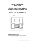
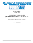
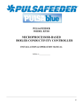
1
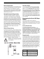
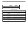
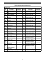
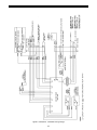
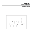
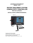
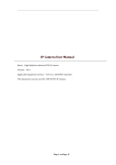
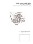
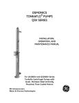
Series 962
Electronic Stager Control
TIME OF DAY
TIME OF REGEN
HARDNESS
FLOW
PM
SERIES 962
CAPACITY
REGEN TIME
REMAINING
SET
REGEN
Table of Contents
Declaration of Conformity . . . . . . . . . . . . . . . . 3
Caution and Warning Symbols . . . . . . . . . . . . 4
Series 962 Electronic Stager Controls. . . . . . . 6
Special Features of the Series 962 Stagers . . 6
Memory Retention
Programmable Cycles
Double Regeneration
Capacity Setting Lockout
Selectable Reserve Options
U.S. or Metric Units of Measure
Calendar Override
Manual Regeneration
Operating Histories
Remote Regeneration
Selectable Automatic Regeneration
Optional Battery Backup
Flow Rate Display
Programming the Series 962 Stager . . . . . . . . 7
Factory Default Values
Program Levels
Level I Programming
Setting Time of Day
Level II Programming
Changing a Program Value
Level III Programming
Level IV Programming
Entering “C” Values
Entering “d” Values
Viewing a Program Value
Manual Regeneration
Lock-out Feature
Flow Sensor Select Options . . . . . . . . . . . . . . 9
Capacity Based Regeneration Start Options . 9
Immediate Regeneration Only Option
Installation Programmed Values Chart
Advance Cycle Function . . . . . . . . . . . . . . . . . 7
Cancel Regeneration Function . . . . . . . . . . . . 7
Parallel Operation . . . . . . . . . . . . . . . . . . . . . 15
Twin Alternating Operation . . . . . . . . . . . . . . 15
Flow Sensor Connections . . . . . . . . . . . . . . . 16
AC Power Wiring . . . . . . . . . . . . . . . . . . . . . . 16
Remote Regeneration . . . . . . . . . . . . . . . . . . 17
Relay Output Option . . . . . . . . . . . . . . . . . . . 17
2
DECLARATION OF CONFORMITY
Rockford Operations
This Declaration of Conformity is suitable to the European standard EN 45014, “General criteria for suppliers’
declaration of conformity.”
Applied Council Directive(s):
Electromagnetic Compatibility Directive, 89/336/EEC Council Directive as amended by Council Directive
92/31/EEC and Council Directive 93/68/EEC.
Low Voltage Directive, 73/23/EEC Council Directive as amended by Council Directive 93/68/EEC.
We,
Manufacturer:
OSMONICS Rockford Opertions
2412 Grant Ave.
Rockford, IL 61103-3991
USA
Authorized
European
Contact:
OSMONICS - France
230 rue Robert Schuman
ZA des Uselles
77350 Le Mee Sur Seine,
France
Tel: 011 -331-64-10-2000
Fax: 011-331-64-10-3747
declare under our sole responsibility that the product(s).
Model E948, E951, E958, E959 and E996 Electronic Controls for Water Filters and
Softeners.
___________________________________________________________________________
to which this declaration relates is (are) in conformity with the relevant provisions of the following Harmonized
European standard(s) or other normative document(s):
Standard & date
EN 61010-1:1993
+ A2:1995
Title
Safety requirements for electrical equipment for measurement, control and
laboratory use - Part 1: General Requirements
Electromagnetic Compatibility - Generic Emission Standard - Residential,
EN 50081-1: 1992
Commercial, Light Industrial.
Electromagnetic Compatibility - Generic Immunity Standard – Part 2 EN 50082-2: 1995
Industrial.
Technical Information is maintained at:
OSMONICS Rockford Operations
2412 Grant Ave.
Rockford, IL 61103-3991
USA
___________________________________________________________________________________________
Year of CE Marking: 2002
_____________________________________________________________________________________________________
We, the undersigned, hereby declare that the product(s) specified above conforms to the listed directive(s) and
standard(s).
Manufacturer
Signature:
Full Name:
Position:
On (date):
Colin J. McDonough
Plant Manager
3
18 Jul 02
Caution and Warning Symbols
and/or circuit breaker must be in close proximity to this
equipment and in easy reach of the operator. It must be
clearly marked to indicate that it is the disconnecting
device for this equipment. Recommend fuse size is
1 AMP.
The following international symbols appear in this
manual to highlight caution and warning messages.
Cautions
Voltage Range: 230/115VAC (+/- 10%)
Not heeding these messages could result in personal
injury and/or damage to equipment.
Frequency Range: 50/60Hz
Max. Rated Power: 4 Watts
Caution: This symbol indicates caution
messages (Refer to User Manual).
Pollution Degree: 2
Overvoltage Category: II
Altitude: 6500 Ft. (2000 Meters)
Warnings
Max. Rated Fluid (Air/Water) Pressures
Not heeding these messages could result in serious
personal injury.
Warning: This symbol is intended to
alert the user to the presence of
“dangerous voltage” within the product’s
enclosure that may be of sufficient
magnitude to constitute a risk of electric
shock to persons.
Model
E948
Model
E951
Model
E958
Model
E959/E996
125 psi
(8.6 bar)
125 psi
(8.6 bar)
125 psi
(8.6 bar)
250 psi
(17 bar)
NEMA 4X Enclosure: Intended for indoor or outdoor
use primarily to provide a degree of protection against
corrosion, windblown dust and rain, splashing water;
undamaged by the formation of ice on the enclosure.
The enclosure door must be kept tightly closed using
all fasteners provided. Any modifications to this
enclosure (i.e., added holes for cable entry/
mounting, conduit connections...etc.) may void the
intended NEMA 4X rating. NEMA 4 and UL rated
fittings should be used when modifying the
enclosure.
Specifications
Warning: Class I equipment - The
composite enclosure used in this
equipment does not automatically
provide grounding between conduit
connections. Use grounding bushing and
jumper wires as part of the installation. To
avoid electric shock, grounding must be installed
by the customer as part of the installation.
Installation should be completed by qualified
electricians and in accordance with the
requirements of all state and local electrical codes
as well as the National Electrical Code (NEC). A
separate ground post has been provided inside this
equipment enclosure and is indicated by the NEC
ground symbol as shown below.
Relative Humidity Operating Range:
NEC Ground Symbol
Warning: Overcurrent Protection - This
equipment is not supplied with built in
overcurrent protection (fuses or circuit
breakers). An external switch and/or
circuit breaker must be installed by a
qualified electrician in accordance with
all state and local electrical codes as well as the
National Electrical Code (NEC). The external switch
4
Temperature Range
Allowed Relative
Humidity
0oC to 37oC
(32oF to 99oF)
10% to 100%
Condensing
38oC to 55oC
(100oF to 131oF)
10% to 75%
Non-Condensing
Inputs
Terminal Strip 1 (TB1) High Voltage
TB1, Terminal #1: Line Voltage Input
TB1, Terminal #4: Neutral Input
TB1, Terminal #6: Input to Aux. Switch Common
Optional Relay Inputs
Relay Terminal #6: Relay Common Input
Terminal Strip 2 (TB2) Low Voltage
TB2, Terminal #11: Turbine Meter Ground Input
TB2, Terminal #12: Turbine Meter Shield Input
TB2, Terminal #13: Turbine Meter Signal Input
TB2, Terminal #17: Delayed Start Input (Dry Contact)
TB2, Terminal #18: Delayed Start Input (Dry Contact)
TB2, Terminal #19: Lockout Input (Dry Contact)
TB2, Terminal #20: Lockout Input (Dry Contact)
Outputs
Terminal Strip 1 (TB1) High Voltage
TB1, Terminal #7: Aux. Switch N.C. Output
TB1, Terminal #8: Aux. Switch N.O. Output
Optional Relay Outputs
Relay Terminal #2: Relay N.C. Output
Relay Terminal #3: Relay N.O. Output
Terminal Strip 2 (TB2) Low Voltage
TB2, Terminal #14: Turbine Meter +12VDC Output
TB2, Terminal #12: Turbine Meter Shield Input
TB2, Terminal #13: Turbine Meter Signal Input
5
Series 962 Electronic Stager
Controls
Double Regeneration
For single tank applications, the control automatically
calls for a second regeneration the following day if the
current operation cycle exceeds the programmed
capacity by 150% or more.
The Series 962 Electronic Stager Controls provide
sophisticated, demand-based water conditioning by
combining a microprocessor with a flow meter to
electronically monitor the amount of water used. This
fully programmable series of controls provide the ability
to fine tune the operation to meet the application
requirements. There are several 962 Stager models
available.
Capacity Setting Lockout
The control can be programmed to lock the capacity so
it cannot be altered after installation.
Selectable Reserve Options
To meet the application requirements, the control
allows selection of one of two reserve types:
Single Unit Controls
Model No.
Basic Softeners & Filters
E948
Complex Softeners & Filters
E951
Fixed Reserve - The reserve is fixed at a
programmable percentage (30% factory preset) of
the total capacity.
Multiple Unit Controls
Twin Alternating Softeners &
Filters
Sequential Filters
(Backwash Only)
2 Unit Sequential Filters
3 or 4 Unit Sequential Filters
Model No.
E958-TA
E958-TB
Variable Reserve - The controller monitors the
daily water usage and at the programmed time of
regeneration, calculates the average water used
for each day of the week. The reserve capacity is
set to 120% of the average water usage for the
next day.
E948
E951
E958
U.S. or Metric Units of Measure
To meet your display and programming requirements,
the 962 Stager uses grains per gallon of hardness and
kilograins of capacity for U.S. units; or parts per million
of hardness and kilograms of capacity as gallons or
cubic meters.
Special Features of the Series 962
Control
Memory Retention
Calendar Override
During a power outage, critical operating information is
stored in nonvolatile memory. This information includes
the time of day, water usage, all programming data and
the number of days since the last regeneration. When
power is restored, the information is returned to the
microprocessor and operation resumes as if an outage
never occurred. The time of day will be late by the
length of the power outage. The time of day should be
reset after an extended power outage. No other
reprogramming is necessary. An optional rechargeable
backup battery will allow the control to keep track of
time and water usage for up to 8 hours during a power
outage. The control will not initiate a regeneration
while on battery backup.
If the volume of water used has not caused a
regeneration, the 962 Stager can be set to regenerate
every one to thirty days.
Manual Regeneration
A separate REGEN button is provided for manual
regenerations. A double manual regeneration feature is
included that allows back-to-back regenerations.
Operating Histories
Important operating data is stored in memory and is
retrievable upon demand.
The historical data includes peak flow data as well as
average daily water usage for each day of the week.
Programmable Cycles
The control is flexible in defining the appropriate cycles
of operation.
6
Remote Regeneration
Flow Rate Display
A set of input terminals with a programmable delay are
provided as a standard feature of the 962 Stager that
allows regeneration to be initiated from a remote
location. This feature can be used to facilitate remote
manual regeneration requirements or assist in further
automating the control system such as the use of a
differential pressure switch.
In the normal operating mode the series 962 Stager
control will alternate between Capacity Remaining
(gallons or m3) and Flow Rate (gallons per minute or
m3/hr). In the event of power loss, (including battery
power) the display will alternate between Time of Day
and Capacity Remaining once power has been
restored. The control will remain in this display mode
until the Time of Day is reset or until any button is
pressed. The flow rate display is indicated by a small
L.E.D. in the top left corner of the display. When P19 is
set to “4” (user defined pulse equivalent) flow rate will
not be displayed.
Selectable Automatic Regenerations
There are four automatic regeneration methods;
“delayed with immediate override”, “delayed only”,
“day of week”, and “calendar override”. Immediate
regeneration is used to start an automatic regeneration
immediately when the capacity remaining in a tank is
reduced to zero. Delayed regeneration is used to start
an automatic regeneration at a predetermined time of
day when the capacity remaining is below a defined
reserve. The reserve capacity may be fixed or variable.
The variable reserve is determined by past usage
history. Regeneration can be accomplished based on
the day of the week at a specific time of day or after
programmable number of days since the last
regeneration.
Programming the Series 962 Stager
Control
This section contains common aspects of
programming the 962 control and retrieving historical
operating data. A label provided with the control should
be filled out with programming parameters on system
start-up.
Factory Default Values
The control is shipped from the factory
pre-programmed with the correct operation type.
Capacity and Hardness values are set to 0 and must
be changed to appropriate values before the control
will operate. “Err 4” will be displayed until a valid
number is entered for each of these items. Program
variable P12 is preset to U.S. units of measure or metric
units to match geographical shipping locations.
Optional Battery Backup
An optional backup battery can be provided so that the
Time of Day and water usage will be maintained for up
to 8 hours during a power outage. All 962 Stager
controls are provided as “Battery Backup Capable”.
Batteries can be purchased separately. The control has
a trickle charge circuit that will recharge the battery in
the event it is depleted by a power outage. If the
optional battery backup is provided with the Series
962, make sure that it is properly connected.
Program Levels
The Series 962 Stager controls have been designed to
facilitate different levels of programming requirements.
Level I includes program variables that are frequently
referenced by users, operators, installers and service
personnel. They are accessible without the requirement
of codes. Level II includes variables that are most
typically used at the time of installation and initial setup.
They are accessible only with access codes. Level III
locations are used primarily for accessing operation
history information. Level IV locations are used to set
the regeneration days of the week. Level III and IV
parameters also require access codes. Programming
levels are further defined in Tables I, II, and III.
Caution: A standard 9V alkaline battery
may be used as a substitute, but will not
be rechargeable.
Levels
I
II
III
Figure 1
7
Access Code
None Required
Press and hold the (↑ ) and (↓)
arrow buttons for 3 seconds
Press and hold the (←) and (↑ )
arrow buttons for 3 seconds
Levels
IV
completed the appropriate changes, press the SET
button. When you press the SET button the new entry
is stored and the control automatically scrolls to the
next P value. If a beep sounds, the new entry was not
accepted. Table 1 lists the range available for a specific
program value.
Access Code
Press and hold the (←) and
(↓) arrow buttons for 3
seconds
Level I Programming
Level I program values are identified by the legend on
the faceplate of the control. A green LED is illuminated
when a Level I "P” value is displayed. Following are the
Level I “P” values:
•
•
•
•
Time of Day
Time of Regeneration
Hardness
Capacity
Level III Programming
Press and hold the (←) and (↑ ) arrow buttons for 3
seconds to enter the Level III programming mode. The
display will show the letter “L” in the far left display
digit. The parameter “L-number” is displayed in the far
right display digit. The SET button is inactive except for
L4. If SET is pressed when L4 is displayed, Peak Flow
is reset to zero. If SET is pressed when any other
location is displayed the control will beep.
P1
P2
P3
P5
P4 is used to program the salt amount. The 962
Stager does not require a salt amount.
Level IV Programming
Setting Time of Day
Press and hold the (←) and (↓) arrow buttons for 3
seconds to enter the Level IV programming mode.
Level IV programming is used to enter the user defined
cycle times and day of week regeneration. All
controllers have default settings for 4 cycle softener or
3 cycle filter operation. The operation type is
determined by the value that is programmed in
“P17”.
Press the SET button. The display will show the time of
day with the minutes digit blinking. Press the UP (↑ )
arrow button to increase the number or the DOWN (↓)
arrow button to decrease the number. To skip the
number without changing, press the LEFT (←) arrow
button. The first digit will stop flashing and the next
digit will start flashing. When the far left digit is reached,
pressing the LEFT (←) arrow button returns the flashing
to the far right digit. Continue changing numbers until
the desired Time of Day is obtained. Press the SET
button to enter the value. The PM indicator will toggle
when the “tens digit” of the hours is increased. The far
left digit is used to indicate the day of week. Number 1
being Sunday and number 7 being Saturday.
Entering "C" Values
"C" values are used to define a specific number of
cycles to meet the application needs and are
accessible through level IV programming mode.
Example: If the control is used in a system that has a
total of 10 cycles of operation, select 6 for P17 and
program C1-C10 for the amount of time desired for
each cycle (up to 255 minutes).
The time of Regeneration, Hardness, and Capacity are
set in a similar manner.
Each "C" value represents 1 position of the rotary pilot
stager that is being used. A maximum of 15 cycles may
be used, each programmable from 0-255 minutes.
Level II Programming
The control will automatically enter Level II
programming if P19 or P20 have not been set.
While the controller is in regeneration the display will
show a “C” value in the far left display and the time
remaining (in minutes) for that “C” value.
Press and hold the (↑ ) and (↓) arrow buttons for 3
seconds to enter the Level II programming mode. The
display will show the letter “P” in the far left display
digit. The parameter “P-number” is displayed in the far
right display digit. See Table 1 for Level I and II
programming values.
Example: [C1 15] = 15 min remaining in C1.
Entering “d” Values (Regeneration Days)
“d” values are used to start a regeneration on a certain
day of the week. There are seven “d” values numbered
from 1 to 7, with 1 representing Sunday and 7
representing Saturday. Set a 1 in “d7” to initiate an
automatic regeneration every Saturday at the Time of
Regeneration (P2). The automatic regenerations will
occur at the time set in P2 regardless of the capacity
remaining in the system. A value of “0” indicates no
regeneration on that day. The default value is “0” for all
“d” values.
Changing a Program Value
Once the P value you want to change is displayed,
press the (←) arrow button to display the current entry
for that value. To change or modify the value, press the
SET button. The digit on the right hand side of the
display will begin to flash. Use the (↑ ) or (↓) arrow
buttons to select the desired entry. Once the desired
entry is obtained, press the (←) button to move to the
next digit and change as needed. Once you have
8
Viewing a Program Value
NOTE: When using the Relay Output Option the
lockout feature cannot be used.
Programmed values may be viewed at any time.
Program values may not be changed during a
regeneration.
Flow Sensor Select Options
P19 is used to select the flow sensor type. Numbers 1
and 2 are for the Autotrol 1 inch and 2 inch turbine type
flow sensors. The number in P20 will be ignored when
P19 is programmed with a 1 or 2.
Level I - To locate and display a P value in Level I press
the (↑ ) or (↓) arrow button until the desired value is
displayed. Level I parameters are indicated by the
legend on the face plate of the control.
Other flow sensors can be used by entering a “3” in P19
and entering the correct “K-factor” in P20. The K-factor
is defined as pulses per gallon for U.S. units or pulses
per liter for metric units. The K-factor can be obtained
from the flow sensor manufacturer.
Level II - To locate and display a P value in Level II,
simultaneously press the (↑ ) and (↓) arrow buttons for
3 seconds to gain access. Press the (↑ ) or (↓) arrow
buttons until the desired location is displayed. Press (←)
to display the value in the P location.
If a “4” is entered in P19 then the definition of the
number in P20 becomes gallons or liters per pulse
depending on the units of measure selected.
Level III - To locate and display an L value in Level III,
simultaneously press the (←) and (↑ ) arrow buttons for
3 seconds to gain access an then press the (↑ ) or (↓)
arrow buttons until the desired location is displayed.
Press (←) to display the value in the L location.
Capacity Based Regeneration Start
Options
Level IV - To locate and display a “d” value in Level IV,
simultaneously press the (←) and (↓) arrow buttons for 3
seconds to gain access and then press the (↑ ) or (↓)
arrow buttons until the desired location is displayed.
Press (←) to display the value in the “d” location.
The following is an explanation of the regeneration start
options for single tank 962 Stager controls.
At the time of regeneration (time set in P2) the control
will check to see if a regeneration should start. This
check depends on the value programmed in P15.
Manual Regeneration
P15 = 0 or 2 Variable Reserve
To initiate a manual regeneration, simply press and hold
the REGEN button for 3 seconds. If an immediate
second regeneration is desired, wait for at least one
minute after the first regeneration begins and then
press and hold the REGEN button for 3 seconds. A
second regeneration will be performed immediately
following the first. The display will freeze and only show
the Regeneration Time Remaining as an indication that
the second regeneration will be initiated. When the first
regeneration is complete, the second regeneration will
begin and the display will alternate between Flow Rate
and Regeneration Time Remaining. The second
regeneration will be performed on the offline tank in
twin alternating applications.
The control calculates an average water usage for each
day of the week when it is using variable reserve. A
regeneration will start if the capacity remaining is less
than 1.2 times the average water usage for the next
day.
P15 = 1 or 3 Fixed Reserve
The reserve capacity is calculated using the fixed
reserve capacity programmed in P16. The value in P16
is the percentage of the calculated system capacity
used for the reserve.
Example: If the programmed capacity is 10,000 grains
and the hardness is 10 grains/gallon the calculated
system capacity is 1000 gallons. The reserve capacity
is 300 gallons if the fixed reserve is set to 30%. A
regeneration will start if the capacity remaining at the
time of regeneration is less than 300 gallons.
Lock-Out Feature
The lock-out feature may also be used to prevent
regenerations when a signal is present at the lock-out
terminals. Two or more 962 controls can be connected
together (see Figure 2) to prevent one from
regenerating while another is in regeneration. This
signal can also come from external equipment that can
provide a dry contact closure. (CONNECTION MUST
BE A DRY CONTACT).
The parameter P15 is also used to select immediate
regenerations or delayed regenerations only.
P15 = 0 or 1 Delayed Regeneration Only
Automatic regenerations will occur at the time of
regeneration only. The control will delay the start of
regeneration until the time of regeneration even if the
capacity remaining is reduced to zero gallons.
9
P15 = 2 or 3 Immediate Regeneration
Override
In addition to delayed regenerations automatic
regenerations will occur at any time during the day if the
capacity remaining reaches zero.
Immediate Regeneration Only Option
Automatic regenerations performed at the time of
regeneration (P2) can be eliminated by setting the
control for fixed reserve with immediate regeneration
override (P15 = 3) and setting the reserve capacity
percentage (P16) to 0%. This will create a reserve
capacity of zero gallons and override the Time of
Regeneration (P2) to allow for an immediate
regeneration. These are the preferred settings for a
Twin Alternating softener system.
Advance Cycle Function
While in a regeneration cycle, you can advance the stager
to the next cycle by pressing and holding the left
arrow key (←) for 3 seconds. The stager and controller
will then advance to the next regeneration cycle.
Cancel Regeneration Function
To cancel (abort) a regeneration, press and hold the left
arrow (←) and SET keys for 3 seconds. The control will
display an ERROR 3 and return the stager to the
service (Home) position. Once in the service position,
ERROR 3 will be cleared.
10
Table 1 - Level I and II Parameters
Parameter
Range of Values
Name
Description
Minimum
Increments
Default
Units of
Measure
(1-7) 1:00-12:59
AM or PM
(1-7) 0:00 -23:59
(1 day)
1 minute
None
hour:minute
Range depends on value
selected for P13.
For day of week, SUN=1,
MON=2, TUE=3, WED=4,
THU=5, FRI=6, SAT=7
1 minute
2:00 am
hour:minute
Range depends on value
selected for P13.
Use only if P15 = 1
1
10
0
0
grains/gallon
ppm
Unit of measure depends value
selected for P12
P1
Day of week and
time of day
P2
Time of day to start
regeneration
1:00-12:59
AM or PM
0:00-23:59
P3
Hardness of water
3-250
30-2500
P4
P5
Notes
Not Used
Capacity of unit
1-5100
.1-510.0
1
.1
0
kilograins*
kilograms*
Unit of measure depends on
value selected for P12
P6
Not Used
P7
Not Used
P8
Not Used
P9
Backwash time
1-30
1
14
minutes
If P17=6 or 9, Do not program P9
P10
Rinse/Draw time
1-125
1
40
minutes
If P17=3, 6, or 9, Do not program
P10
P11
Rinse time
1-19
1
4
minutes
If P17=6 or 9, Do not program
P11
P12
Units of measure
0-1
1
0
0 = US, 1 = Metric
0 = 12 hour clock
1 = 24 hour clock
P13
Clock mode
0-1
1
0
P14
Calendar override
0-30
1
0
P15
Reserve Type
0-3
1
0
P16
Initial average
usage or fixed
reserve
0-70
1
30
days
0 = no calendar override
0 = Variable reserve, 1 = fixed
reserve, 2 = variable reserve with
immediate regeneration, 3 = fixed
reserve with immediate regen
% of capacity
Description depends on value
entered for P15
P17
Operation type**
3-9
1
4
0 - 2 = Not Used, 3 = 3 cycle filter
4 = 4 cycle softener, 5 = 4 cycle
(180/182) butterfly config.,
6 = User defined cycle times***.,
9 = User defined (58-TB only).***
P18
Capacity change
lock-out
0-1
1
0
0 = None, 1 = Capacity change
locked-out
1
3
1 = 1.0” Autotrol turbine, 2 = 2.0”
Autotrol turbine, 3 = User defined
K-factor (PPG), 4 = User defined
pulse equivalent (GPP)
.01
0.01
1
60
P19
Flow sensor select
1-4
P20
K-factor or pulse
equivalent
0.01-255.00
P21
Remote
regeneration switch
delay
1-254
Number used for meter
K-factor or pulse equivalent
seconds
Time remote switch must be
active to start a regeneration
* See Table 2 for conversions.
**When using options 6 or 9 programming “C” values per Table 3 eliminates the need to program P9 through P11.
***Program “C” values per Table 4.
.
11
Table 2 Conversions
To Convert Capacity
in
kilograms (kg)
kilograins (kgr)
moles of CaCO3
equivalents of CaCO3
Into Capacity in
Multiply by
kilograins (kgr)
kilograms (kg)
kilograms (kg)
kilograms (kg)
15.43
0.0648
0.10
0.05
Table 3 Level III History Data
Location
L1
L2
L3
Range
1-7
0-255
1:00-12:59/0:00-23:59
L4
0-200/0-50.0
L5
L6
L7
L8
L9
L 10
L 11
L 12
L 13
L 14
L 15
0-655360/0-6553.6
0-655360/0-6553.6
0-655360/0-6553.6
0-655360/0-6553.6
0-655360/0-6553.6
0-655360/0-6553.6
0-655360/0-6553.6
0-655360/0-6553.6
0-655360/0-6553.6
0-999990/0-99999.9
0-167/0-16
Description
Day of week (Sun=1, Sat=7)
Days since last regeneration
Time that peak flow occurred
Peak flow gallons per minute/cubic meters (M3) per hour since
location reset
Water used today in gallons/M3 since time of regeneration
Water used since last regeneration in gallons/M3
Average water usage for Sunday in gallons/M3
Average water usage for Monday in gallons/M3
Average water usage for Tuesday in gallons/M3
Average water usage for Wednesday in gallons/M3
Average water usage for Thursday in gallons/M3
Average water usage for Friday in gallons/M3
Average water usage for Saturday in gallons/M3
Total water used since NOVRAM test in gallons/M3 (LSD)
Total water used since NOVRAM test in gallons/M3 x 106 (MSD)
12
Table 4 Level IV Parameters
#
Description of Parameter
Range of Values
C1
C2
C3
C4
C5
C6
C7
C8
C9
C10
C11
C12
C13
C14
C15
d1
d2
d3
d4
d5
d6
d7
Position 1 Cycle Time
Position 2 Cycle Time
Position 3 Cycle Time
Position 4 Cycle Time
Position 5 Cycle Time
Position 6 Cycle Time
Position 7 Cycle Time
Position 8 Cycle Time
Position 9 Cycle Time
Position 10 Cycle Time
Position 11 Cycle Time
Position 12 Cycle Time
Position 13 Cycle Time
Position 14 Cycle Time
Position 15 Cycle Time
Sunday
Monday
Tuesday
Wednesday
Thursday
Friday
Saturday
0 min -255 min
0 min -255 min
0 min -255 min
0 min -255 min
0 min -255 min
0 min -255 min
0 min -255 min
0 min -255 min
0 min -255 min
0 min -255 min
0 min -255 min
0 min -255 min
0 min -255 min
0 min -255 min
0 min -255 min
0-1
0-1
0-1
0-1
0-1
0-1
0-1
Minimum
Increment
1 min
1 min
1 min
1 min
1 min
1 min
1 min
1 min
1 min
1 min
1 min
1 min
1 min
1 min
1 min
1
1
1
1
1
1
1
Default
Notes
0
0
0
0
0
0
0
0
0
0
0
0
0
0
0
0
0
0
0
0
0
0
Stager Cycle (P17=6 or 9)
Stager Cycle (P17=6 or 9)
Stager Cycle (P17=6 or 9)
Stager Cycle (P17=6 or 9)
Stager Cycle (P17=6 or 9)
Stager Cycle (P17=6 or 9)
Stager Cycle (P17=6 or 9)
Stager Cycle (P17=6 or 9)
Stager Cycle (P17=6 or 9)
Stager Cycle (P17=6 or 9)
Stager Cycle (P17=6 or 9)
Stager Cycle (P17=6 or 9)
Stager Cycle (P17=6 or 9)
Stager Cycle (P17=6 or 9)
Stager Cycle (P17=6 or 9)
0 = no day of week regen this day
0 = no day of week regen this day
0 = no day of week regen this day
0 = no day of week regen this day
0 = no day of week regen this day
0 = no day of week regen this day
0 = no day of week regen this day
Note: The number of “C” values MUST equal exactly the number of stager regeneration cycles.
Example: If the parameter “Position 5 Cycle Time” is programmed then C1 through C4 must also be programmed.
Table 5 Error Code Identification
Error Code
1
2
3
4
5
Description
Data stored in NOVRAM has been corrupted and is incorrect
Home switch (SW 2) closed when it should be open
Home switch (SW 2) open when it should be closed
One or more parameters are below the minimum value in Table I
System capacity less than 10 gallons or 0.1 m3 (Capacity is set too low or Hardness is
set too high)
13
Table 6 Installation Programmed Values Chart
Installation Date:
“P”
Value
Description
Install Values
“C”/”d”
Value
Description
P1
Day of week/Time of
day
C1
Position 1 Cycle Time
P2
Time of regeneration
C2
Position 2 Cycle Time
P3
Hardness of water
C3
Position 3 Cycle Time
P4
Not used
C4
Position 4 Cycle Time
P5
Capacity of unit
C5
Position 5 Cycle Time
P6
Not used
C6
Position 6 Cycle Time
P7
Not used
C7
Position 7 Cycle Time
P8
Not used
C8
Position 8 Cycle Time
P9
Backwash time
C9
Position 9 Cycle Time
P10
Rinse/Draw time
C10
Position 10 Cycle Time
P11
Purge time
C11
Position 11 Cycle Time
P12
Units of measure
C12
Position 12 Cycle Time
P13
Clock Mode
C13
Position 13 Cycle Time
P14
Calendar override
C14
Position 14 Cycle Time
P15
Reserve type
C15
Position 15 Cycle Time
P16
Initial average value or
fixed reserve capacity
d1
Regenerate on Sunday
P17
Operation type
d2
Regenerate on Monday
P18
Capacity change lock
out
d3
Regenerate on Tuesday
P19
Turbine select
d4
Regenerate on Wednesday
P20
K-factor or pulse
equivalent
d5
Regenerate on Thursday
P21
Remote regeneration
switch delay
d6
Regenerate on Friday
P22
Factory use only. Do not program.
d7
Regenerate on Saturday
14
Install Values
Parallel Operation
regeneration. This lock-out signal will prevent other
controls from starting a regeneration when the controls
are connected as in Figure 2.
The 962 Stager control can be used for twin and triple
tank applications, operating in a parallel mode. Parallel
systems can be implemented with up to three
individual controls by using the lock-out feature. Each
control will provide a lock-out signal when it is in
Figure 2 Parallel/Interlock Connections
NOTE: The lockout feature is void when using the relay output option.
Twin Alternating using a model 58-TA
stager
Twin Alternating using a model 58-TB
stager (Timed Brine)
The 962 Stager control can be used for Twin Alternating
applications by combining a single 962 controller with
a single model 58-TA Twin Alternating stager. The
alternating of the system is performed by the stager
and is independent of the controller. When using a
model 58-TA, the “Tank in Service” is indicated by two
NEMA 4 rated door-mounted lights that are operated
by the stagers second auxiliary switch. When using a
model 58-TA Twin Alternating stager, P17 must be
set to a 4 or 6 depending on the number of
positions.
The 962 Stager control can be used for Twin Alternating
applications that require a timed brine function by
combining a single 962 controller with a single model
58-TB stager. The 58-TB stager does not use
door-mounted lights to indicate the “Tank in Service”.
The controller will display the “Tank in Service” in the
left-most digit of the 6-digit display. It will display a 1 or
2 depending on which tank is in service. Flow is also
displayed during this time. If any error condition occurs,
the “Tank in Service” display will be set to a 2 by
default. The controller will reset the display to the
proper tank in service once a regeneration is performed
on any tank. When using a model 58-TB Twin
Alternating stager, P17 must be set to a 9.
15
Flow Sensor Connections
The 962 Stager control may be connected to a number
of different flow sensing devices. Figure 3 shows the
connections for the Autotrol turbine type flow sensor.
Figure 4 shows the connections for the Signet flow
sensor. Most of the flow sensors that are used will be
wired similarly, though the wire colors may vary.
GREEN
11
SHIELD
(BARE)
GREEN
11
WHITE
12
GROUND
(WHITE)
WHITE
12
SHIELD
(BARE)
BLACK
13
SIGNAL
(BLACK)
BLACK
13
SIGNAL
(RED)
RED
14
+12VDC
(RED)
RED
14
+12VDC
(BLACK)
Turbine
Probe
TB2 - (LOW VOLTAGE)
Flow
Sensor
TB2 - (LOW VOLTAGE)
Figure 3 Autotrol Flow Sensor Connections
Figure 4 Signet Flow Sensor Connections
AC Power Wiring
The 962 Stager controls have standard
voltage configurations of 115 VAC 50/60
Hz, or 230 VAC 50/60 Hz. Power
requirements must be specified when
ordering. For 115 VAC jumpers are placed between
terminals 1 and 3 and 2 and 4. For 230VAC jumpers
are placed between terminals 2 and 3 only, Figure 5.
Line voltage and neutral inputs are always on terminals
1 and 4 respectively.
115 VAC 50/60 Hz
BLUE
4
RED
3
WHITE
2
BLACK
1
230 VAC 50/60 Hz
NEUTRAL IN
JUMPER
LINE VOLTAGE IN
BLUE
4
RED
3
WHITE
2
BLACK
1
TB1 - (HIGH VOLTAGE)
TB1 - (HIGH VOLTAGE)
Figure 5 AC Power Connections
16
NEUTRAL IN
JUMPER
LINE VOLTAGE IN
Remote Regeneration
A set of terminals with a programmable delay (P21) are
provided as a standard feature of the 962 control,
Figure 6. This feature allows for a regeneration to be
initiated from a remote location. This feature can also
be used to accommodate a differential pressure switch
input or any dry contact closure from external
equipment. Programmable value “P21” is used to
monitor this input for the amount of time that is
programmed (in seconds).
P21 is the length of time (in seconds) that the remote
input signal will be ignored before starting a
regeneration. (CONNECTION MUST BE A DRY
CONTACT).
Figure 6 Remote Regeneration Start Connections
Relay Output Option
A single pole double throw (SPDT) relay may be added
for outputs during Regeneration and Service mode.
The relay output option is available on single unit and
Twin Alternating models only. This feature may not be
used however, with the parallel multi-tank systems
using the lockout feature. The contacts of this relay are
supplied as "Dry Contacts” (un-powered). See Figures
7 and 8 for wiring information.
NOTE: The lockout feature is void when using the relay
output option.
Figure 7 Relay Output Option
17
Figure 8 E948/E951 Standard Wiring Design
18
19
Rockford Operations
2412 Grant Avenue, Rockford, IL 61103-3991, USA, Phone (815) 964-9421, Fax (815) 964-4449
© 2002 Osmonics, Inc.
Printed in the USA
06/02
P/N 1076301 Rev. D