1
BEV RITE
WM-800 RO
WATER PURIFICATION SYSTEM
Troubleshooting & Service Manual
Company Information
Company:
Contact:
Phone:
Fax:
Email:
Machine Information
Installation Date:
Model Number:
Serial Number:
Service Assistance
Consult the Troubleshooting Section. If the problem cannot be
identified and corrected, contact your distributor. Prior to
making the call, have the following information available:
Model Number
Serial Number
Installation Date
Daily Log Sheets
Operating Parameters
Description of Problem
Spare Parts
Contact your distributor to order spare parts. Refer to the
Spare Parts List.
NOTE: This manual, along with all GE Infrastructure manuals, is
available at www.gewater.com.
Reverse Osmosis
Water Treatment System
Service Manual
Table of Contents
Page
System Overview
Description of Operation
Pretreatment System
RO System
Delivery System
Diagrams
Piping and Instrumentation Diagram
RO Electrical Schematic
Controller Displays
Normal Operating Cycle Displays
Error Message Displays
Operator and Technician Menus
Startup and System Adjustments
Troubleshooting
No Water
Poor Water Quality
Excessive Flow to Drain
Other
Test Procedures
Pre-filter Cartridges
Summary: Inlet and Tank Pressure Switches
Inlet Pressure Switch
Tank Pressure Switches
Inlet Solenoid Valve
Flush Solenoid Valve
Pump and Motor
Membrane Element Production
Service Procedures
Pre-filter Cartridge Replacement
Post Filter Cartridge Replacement
Membrane Element Replacement
1
2
2
3
5
6
6
7
8
8
9
10
11
12
12
13
14
15
16
16
17
18
19
22
24
25
28
29
29
30
31
Page
Part Diagrams
Storage Tank
Pre- Filter assembly
RO System
Membrane Element Housing
RO Inlet Manifold Assembly
RO Concentrate Manifold Assembly
RO Product Manifold Assembly
RO Controller
Post Filter assembly
Return Goods Authorization (RGA) Procedure
Warranty
Appendix
Routine Maintenance Log
Routine Maintenance Schedule
33
34
36
38
41
42
44
46
48
50
51
53
54
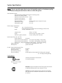
CAUTION
To avoid damage to the RO system pump, shut OFF the RO when the system bypass valve is
in the bypass position.
System Components
Water Softener
GE Water - ReadySoft or AdvantaPure
Pre-filter Assembly
GE Osmonics BEV Rite TO-320
Reverse Osmosis Processor
GE Osmonics BEV Rite WM-800
Post Filter Assembly
GE Osmonics BEV Rite PF-110
Storage Tank
RO mate RO30, or equivalent
Service and Technical Support
GE Osmonics customer support center:
fax:
(800) 848 - 1750
952 - 933 - 2277
952 - 988 - 6030
www.gewater.com
Mail can be sent to:
GE Osmonics, Inc.
Attn: Customer Support Center
5951 Clearwater Drive
Minnetonka, MN 55343-8995 USA
NOTE:
This manual, along with all GE Infrastructure manuals, is available at www.gewater.com.
System Specifications
Note ! Do not use with water that is micro-biologically unsafe or of unknown quality
without adequate disinfection before or after the system
Inlet feedwater supply:
Must meet EPA and WQA specifications for drinking water.
Maximum Silt Density Index:
3
Maximum free chlorine content: 3 ppm
Minimum inlet pressure:
10 psi
Maximum inlet pressure:
95 psi
Flow requirement:
3.5 gpm (gallons per minute) [13.3 Lpm]
Operating pH range:
4.0 - 11.0
Cleaning pH range:
2.0 - 11.5
Power supply requirements:
Voltage:
Amps:
110 - 120 volts AC, 60 Hz
Single phase with grounded neutral and safety ground (3-wire)
15 Amp, (dedicated circuit)
Largest motor:
Pump:
Maximum system pressure:
3/4 Hp (0.75 Hp)
Procon rotary vane, 4 gpm, 170 psi.
170 psi (safety relief on pump)
Rated output from tank (@ 77°F):
Output pressure:
45-60 psi
Flow @ 115 psi pump pressure: 21-31 gph (593 gal/day, +25%/-15%)
Flow @ 170 psi pump pressure: 37-55 gph (1,050 gal/day +25%/-15%0
Typical; 55°F, 170psi pump pressure, 50psi output = 29 gph (700 gal/day)
System Recovery:
50% nominal (adjustable 25% - 75%)
Salt Rejection:
greater than 90%
TO-320 Taste & Odor Removal Filter:
Operating temperature:
Design Flow Rate:
Max. working pressure:
Chlorine capacity:
40-100°F
6 GPM
100 psi
60,000 gallons @ 1ppm (typical) (~60 days @ 1,000 gpd)
(or ~120 days @ 500 gpd avg.)
Certifications:
Listed by Underwriter’s Laboratories
for USA and Canada
Industrial Control Panel
E204722
WM-800 RO System tested and certified by NSF International
to ANSI/NSF Standard 58 for the reduction of TDS.
TO-320 Taste & Odor Removal Filter tested and certified by
NSF International to ANSI/NSF Standard 42 for the reduction
of chlorine.
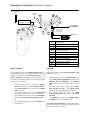
System Overview
To Water
Heater
TO STORE EQUIPMENT
Ice machine, Coffee/Tea Brewers,
Water dispenser, etc.
Pre-filter Assembly
Domestic Water
Service
Post Filter
RO System
Booster Pump
If service is <20 psi
Water Softener
Storage
Tank
Pre-Filter Flush Line
(3/8” OD Tube)
RO Concentrate (4 gpm)
(3/8” OD Tube)
Post Filter Flush Line
(3/8” OD Tube)
Softener Drain
(1/2” ID Hose, 2 gpm)
Brine Tank Overflow
(1/2” ID Hose)
To Indirect Drain
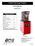
The Reverse Osmosis (R) system is comprised of five separate water treatment stages.
Stage 1: Water Softener
Stage 3: RO System
The water softener removes hardness minerals
(primarily calcium and magnesium carbonate)
from the water and supplies softened water to the
water heater and the RO system.
The RO system removes virtually all remaining
contaminants from the water. In fact, RO water is
so pure that minerals must be added back before
using for brewing.
Softened water helps the RO operate more efficiently and protects the water heater from scale.
Step 4: Storage Tank
The storage tank stores the water and pressurizes
it for supply to the store. The tank is sealed to
preserve the purity of the water.
Stage 2: Pre-filter Assembly
The pre-filter removes particulate matter and
chlorine from the water. The pre-filter helps the RO
operate more efficiently, protects the RO membrane element from chlorine damage.
Step 5: Post filter
The post filter contains a combination of minerals
and activated carbon. As the water flows through
the post filter, a small amount of the minerals
dissolve into the water, and the carbon absorbs
any trace organics, improving the taste.
1
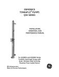
Description of Operation: Pretreatment System
Domestic Water
Service
To Water
Heater
P3
P2
P4
P5
P1
Booster Pump
If service is < 20 psi
B1
S1
TO STORE
EQUIPMENT
P7
S4
S3
S2
P6
System Bypass
Valve shown in
normal position
P8
From RO
TO RO
SYSTEM
S5
S1
S2
S3, S4
S5
P1
P2
P3
P4
P5
P6
P7, P8
B1
Control Valve
Bypass Valve
Media Tanks
Brine Tank
Pre-filter Inlet Valve
Pre-filter Inlet Pressure Gauge
Pre-filter Outlet Pressure Gauge
Pre-filter Flush Valve
Pre-filter Outlet Valve
Sediment Filter Housing
Carbon Filter Housings
System Bypass Valve
Water Softener
Pre-Filter
During operation, one of two media tanks (S3, S4), is in
service while the other is in standby. Flow through the
system is metered by the control valve (S1). The
control valve (S1) automatically switches tanks and
performs regeneration based on the volume of water
flow through the softener.
Water flows through three filter housings (P6 - P8)
plumbed in series.
•
•
•
•
•
Domestic water enters the softener bypass
valve (S2) and flows into the control valve (S1).
The control valve directs the flow to the media
tank in-service.
The ion-exchange resin in the media tank
removes the hardness minerals from the water.
The softened water flows out of the media tank
through the control valve and bypass valve outlet.
The softener water tees off the pre-filter and
water heater.
2
•
•
•
•
Softened water enters the inlet valve (P1), passes the inlet pressure gauge (P2) and enters the
sediment filter housing (P6). The sediment
filter removes fine particulate matter from the
water.
The water then flows through each carbon
filter housing (P7, P8). The carbon filters
remove chlorine (and taste) from the water.
The filtered water flows past the outlet
pressure gauge (P3) and goes to the outlet
valve (P5).
The pre-filter outlet goes to the system bypass
valve (B2) then out to the RO system.
The pre-filter flush valve (P4) is used to relieve pressure from the filters for service and for checking the
pressure drop across the filters.
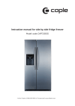
Description of Operation: RO System
The RO is controlled by a microprocessor based
control (R21).
Filling the Storage Tank and Stopping
the RO
Starting the RO
•
•
•
•
•
•
•
•
As water is drawn from the storage tank (T1),
tank pressure drops.
When the tank pressure drops below 60 psi, the
tank HI pressure switch (R19) closes.
When the tank pressure drops below 45 psi, the
tank LO pressure switch (R17) closes.
With both tank pressure switches closed, the
RO starts to run a cycle.
The inlet solenoid valve (R5) opens, allowing
the filtered water to flow into the system.
When the inlet water pressure reaches 8 psi, the
normally closed inlet pressure switch (R7)
opens.
After a three second delay, the pump
(R1 - R3) starts.
Producing RO Water
•
•
•
•
•
•
The pump forces water into the membrane element housing (R8). Pump pressure is indicated
on the pump discharge pressure gauge (R4).
The membrane element inside the membrane
element housing filters the water into two
streams: product water (pure water) and concentrate water (waste water).
The concentrate stream leaves the membrane
element and enters the concentrate manifold
(R10), where the stream is split and redirected.
• The concentrate valve (R13) controls the
flow of water through the concentrate flow
meter (R25) and out to the drain. It controls the amount of waste (% Recovery) and
purity, and affects system pressure.
• The pressure regulator (R12) controls the
flow of concentrate water that is returned
to the pump inlet, and affects product flow.
• The concentrate valve and pressure regulator valve together control the RO operating pressures shown on the concentrate
pressure gauge (R11) and pump pressure
gauge (R4), and sets the product flow.
The product stream leaves the membrane element through the center port and passes
through the product check valve (R16) into the
product manifold (R15).
Product water quality (TDS) is measured at the
product manifold by the conductivity sensor
(R14).
Product water exits the product manifold, flows
through the product flow meter (R22) and out
to the storage tank.
3
•
•
•
•
Tank pressure, shown on the tank pressure
gauge (R18), increases as the storage tank is
filled.
When the tank pressure reaches 60 psi, the
tank HI pressure switch opens.
The flush solenoid valve (R9) opens for a 20
second flush of the membrane element.
The flush solenoid valve closes and the pump
deactivates.
The inlet solenoid valve closes, and the RO
goes into standby until water is used from the
storage tank and pressure drops below 45 psi
again.
Normal Operating Pressures
Pump (R4)
160 - 175 psi
Concentrate (R11)
130 - 160 psi
Product (R18)
45 - 60 psi
Normal Operating Flow Rates
Product Flow
26 - 45 gph
Concentrate Flow
26 - 45 gph
Actual output depends on water temperature and membrane element.
To view water temperature:
• Press and hold both the
ENT and DOWN arrow keys
to enter the Technician
menu.
• Use the UP or DOWN arrow
keys to scroll to the Product
Quality screen, then press
ENT.
• Use UP or DOWN keys to
scroll to Temperature
DOWN key
ENT key
Expected product flow for various temperatures, with 170psi
pump pressure (R4) and 50psi Tank pressure (R18).
Water
Temp °F
Product Flow, %Recovery
35°
45°
55°
65°
77°
16.4-24 gph, 27-35.6%
20-29.4 gph, 31-40%
24.5-36 gph, 36-45%
29.7-44 gph, 40-50%
37-54.7 gph, 46-55%
Gallons
per Day
520
635
775
940
1050
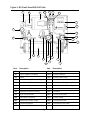
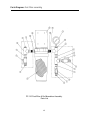
Figure 1: RO Front View With Call-Outs
R3
R1
R2
R24 R23
R25
R22
R21
R20
R4
R19
R18
R5
R17
R16
R7
R8
R6
R11
R9
R14
R12
R10
Item
Description
R13
Item
R15
Description
R1
Motor
R14
Conductivity Sensor
R2
Motor Adapter & coupling
R15
Product Manifold
R3
Pump
R16
Product Check Valve
R4
Pump Discharge Pressure Gauge
R17
Tank LO Pressure Switch (45 psi)
R5
Inlet Solenoid Valve
R18
Tank Pressure Gauge
R6
Inlet Manifold
R19
Tank HI Pressure Switch (60 psi)
R7
Inlet Pressure Switch
R20
Power Switch
R8
Membrane Element Housing
R21
Controller
R9
Flush Solenoid Valve
R22
Product Flow Meter
R10
Concentrate Manifold
R23
Product Outlet
R11
Operating Pressure Gauge
R24
Concentrate Outlet
R12
Pressure Regulator
R25
Concentrate Flow Meter
R13
Concentrate Valve
4
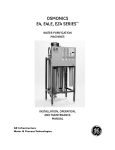
Description of Operation: Delivery System
To Beverage Equipment
Coffee/Tea Brewers,
Ice Machine, etc.
Tank pre-charge Air pressure
valve stem (30-35 psi)
(under cap)
B1
F3
T5
F4
F1
F5
T1
F2
T3
T3
T4
The storage tank (T1) has an internal rubber bladder pressurized
with air. The tank pressure can be checked and adjusted through
the tank air fitting (T5). The tank can be bypassed by closing the
tank isolation valve (T4).
•
•
•
•
•
Product water flows from the RO into the tank inlet (T2).
As the storage tank fills with water, the bladder is
compressed and the tank pressure increases.
Water flows from the tank outlet (T3) to the post filter
inlet valve (F1).
The remineralization cartridge inside the post filter
pressure gauge (F2) adds a small amount of
minerals into the water and removes any organics.
Water passes the post filter pressure gauge (F3), flows
out the post filter valve (F4) to the system bypass
valve (B1) and out to the beverage equipment.
The post filter flush valve (F5) is used for flushing the post filter
cartridge, to relieve the line pressure when servicing the post
filter, and to de-pressurize the storage tank.
5
T1
Storage Tank
T2
Tank Inlet
T3
Tank Outlet
T4
Tank Isolation Valve
T5
Tank Air Fitting
F1
Post Filter Inlet Valve
F2
Post Filter Housing
F3
Post Filter Pressure Gauge
F4
Post Filter Outlet Valve
F5
Post Filter Flush Valve
B1
System Bypass Valve
6
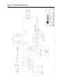
1. Flows shown represent 25-50% recovery range, at 77oF
2. Actual flows may vary +25% to -15% depending on membrane.
3. Reference drawing #1154296 for symbol legend.
NOTES:
Operating pressure
gauge (R11)
Product
Check
Valve (R16)
Inlet
Pressure switch
8 psig (R7)
Pressure
Regulator (R12)
Membrane
Element (R8)
Flow: 175-88 GPH
(210 GPH during Flush)
Inlet
solenoid
valve (R5)
Concentrate
Valve (R13)
Flush
solenoid (R9)
(R4)
Tank Low Tank High
(R17)
(R19)
Pressure switches
Flow: 132-44 GPH
(180 GPH during Flush)
Flow: 44 GPH
(30 GPH during Flush)
TDS
sensor
(R14)
Product
Pressure
Gauge (R18)
(R3)
Pump
Pressure
(R4)
Concentrate
Flow sensor
(R25)
Product
Flow sensor
(R22)
To Drain
To store
equipment
Figure 2: Piping and Instrumentation Diagram
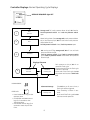
Figure 3: RO Electrical Schematic
7
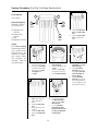
Controller Displays: Normal Operating Cycle Displays
SERVICE REQUIRED light OFF
1
IDLE
Tank Full
Storage tank full, tank pressure above 60 psi, RO inactive
Tank HI pressure switch and tank LO pressure switch
open
IDLE
Water being drawn from storage tank, tank pressure below
60 psi and above 45 psi (RO will start when tank pressure
drops below 45 psi).
Tank HI pressure switch closed, Tank LO pressure open.
2
RO running and filling storage tank (RO will run until tank
pressure reaches 60 psi).
Tank HI pressure switch closed Tank LO pressure switch
open (Tank LO pressure switch closed when tank pressure
below 45 psi).
RUNNING
3
Displays Alternate
4
RUNNING
Tank Full
RUNNING
Flushing 20s
Tank pressure at 60 psi, RO in an
automatic flush cycle.
The time remaining for the flush cycle
is shown in seconds.
At the end of the flush cycle the RO
shuts down and returns to IDLE Tank
Full.
DOWN ARROW:
Alternate Message
ENTER KEY:
ENT
RUNNING
Flushing 120s
• Press DOWN Arrow key to view
Operator Menu
• Hold ENTER and DOWN Arrow
keys for 3 seconds to view
Technician Menu
• Hold ENTER and ESC keys for 4
seconds to reset the pre-filter
timer.
8
If the RO has run for over 1 hour, a
flush cycle will be triggered.
Time remaining is shown in seconds.
At the end of the flush cycle the RO
resumes normal operation.
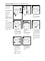
Controller Displays: Error Message Displays
SERVICE REQUIRED Light ON and STEADY
Displays Alternate
Error Message
IDLE
Service Required
Low Inlet Pressure
A low inlet pressure event occurred.
RO will operate normally and restart
within two minutes. “Service Required”
will display constantly during restart.
See Troubleshooting: No Water.
RUNNING
Service Required
Change Pre-filters
IDLE
RUNNING
Service Required
Product Quality
IDLE
RUNNING
Service Required
Low Product Flow
IDLE
The filter change timer has expired.
RO will operate normally until reset.
See Service Procedure: Pre-f ilter
Change.
Product water quality exceeds
set point (TDS > 220 ppm).
RO will operate normally.
See Troubleshooting: Poor
Quality.
Water
Product water flow rate below set point
(10 gph).
RO will operate normally
See Troubleshooting: No Water.
SERVICE REQUIRED Light ON and Flashing
Service Required
Low Inlet Pressure
Four low inlet pressure events during normal
operation occurred (not during flush).
RO will attempt to start every 15 minutes.
See Troubleshooting: No Water.
Service Required
Change Pre-filters
Three consecutive low inlet pressure events
occurred during a Tank Full flush.
RO has shut down
Turn RO OFF and ON. Check pre-filters.
See Test Procedure: Pre-f ilter Cartridges.
9
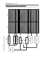
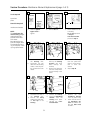
Figure 4: Controller Displays: Operator and Technician Menus
10
Startup and System Adjustment:
Note: All connected water using equipment must not be used during this procedure.
Install all system components and piping according to the guidelines provided.
1
Preliminary checks
2
a. Check to be sure that the Pre-Filter Flush valve
(P4) is closed, and the Pre-Filter Inlet and Outlet
valves (P1) and (P5) are both open.
b. Place the System Bypass Valve (B1) and Softener
Bypass valve (S2) (if used) into the ‘normal’ (not
bypass) position.
c. Check all tubing connections to see that the system is connected properly according to the diagram shown on page #1, and that the drain tubes
are secure and directed to an adequate drain.
d. Be sure that the Tank Isolation valve (T4) is open,
and the Post-Filter inlet and outlet valves (F1 and
F4) are both open, and that the Post-Filter Flush
valve (F5) is closed.
e. On initial startup, and at least every 6-months,
drain the tank fully and check the tank pre-charge
Air pressure (T5), adjust if necessary to 30-35 psi.
f. Check the Pre-Filter pressure gauge (P3) for 10-95
psi, if not, make sure that all upstream valves are
open, and that the supply piping is correct.
g. If the Product Pressure gauge (R18) shows more
than 45psi, open the Post-Filter Flush valve (F5) to
drain the Tank until the tank pressure (R18) drops
below 40 psi.
3
Power On
a. Connect the RO power cord to a dedicated 115vac,
20 amp electrical outlet.
b. Turn the RO ON with the Power On switch (R20).
c. Be prepared to shut the RO off quickly if the pump
makes a loud “grinding” sound.
d. The Display should light up and show a brief message, then the Inlet Solenoid will open. After a 3
second delay, the Pump should start and the
Display shows ‘Running’. (If not, refer to the
Troubleshooting section.)
e. If the pump makes a ‘grinding’ sound, turn the
system OFF for 10-15 seconds, then switch it ON
again and watch the Pre-Filter Outlet gauge (P3)
to see that the feed water pressure remains above
20psi when the Pump comes on. If not, check all
upstream piping and equipment for malfunction.
f. If the Pre-filter pressure at (P3) remains greater
than 20psi, the pump may simply be dry, and
needs to turned OFF and ON again for a few seconds several times in order to ‘prime’ it.
g. The pump Pressure gauge (R4) should show 100175psi. If not, see Test Procedure: Pump and Motor.
4 RO Final Adjustments
Set Recovery and Pump Pressure
a. As the product pressure gauge (R18) approaches
50 psi, repeat steps 3b and 3c as necessary to
maintain a pump discharge pressure (R4) of 170
psi and a Concentrate Flow of 40-45 gph.
R4
R18
Troubleshooting: (see Troubleshooting section)
R13
R12
a. Press the DOWN arrow key twice
to display Concentrate Flow.
READ STEPS b AND c BEFORE PROCEEDING
b. With the RO running, adjust the concentrate
valve (R13) until the Concentrate Flow shows 4045 gph. Make sure the pump discharge pressure (R4)* remains below 175 psi while adjusting
the concentrate valve (13).
c. Adjust the pressure regulator valve (12) until the
pump discharge pressure (9) reads 170-175 psi.
d. Repeat steps b and c as necessary.
11
*Note: The Pump has a built-in safety relief valve
which is factory set at 175 psi, so care should be
taken to always adjust the Pressure Regulator
(R12) slightly below 175 psi. When the water
becomes colder during winter months, pressures will tend to increase, periodic adjustment
may be required.
YES
12
(no display)
NO
IDLE
NO
RO repeatedly turns
ON, runs for less than
five minutes, and
turns OFF
YES/NO
RUNNING
Service Required
Low Product Flow
Service Required
Change Pre-filters
Service Required
Low Inlet Pressure
MESSAGE
Is the SERVICE REQUIRED light ON or FLASHING?
YES
YES
See Test Procedure: Pump and Motor
See Test Procedure: Flush Solenoid Valve
See Test Procedure: Membrane Element Production
Pump failure
RO flush solenoid valve stuck open
Membrane or product flow meter failed
See Test Procedure: Membrane Element Production
Membrane element fouled
Plug in RO
Turn power switch ON
Turn power switch OFF and ON
Locate panel and reset breaker
Replace fuse
Open tank isolation valve (t4)
Drain storage tank and add air (15 psi)
See Test Procedure: Tank Pressure Switches
RO Power switch OFF
Controller circuit breaker tripped
Electrical breaker tripped
Controller fuse blown
Tank isolation valve closed
No air precharge in storage tank
Tank pressure switch failure
See Test Procedure: Tank Pressure Switches
RO unplugged
Open post filter inlet valve (F1) or outlet valve (F4)
Tank LO pressure switch failed
Place system bypass (B1) valve in normal position
Post filter/outlet valve closed
System bypass valve in bypass position
Contact the store’s facilities service department
See Test Procedure: Flush Solenoid Valve
RO flush solenoid valve stuck open
Usage exceeds system capacity
See Test Procedure: Pump and Motor
Pump motor failed
See Test Procedure: System Adjustments
See Test Procedure: System Adjustments
RO system adjusted improperly
Open tank isolation valve (T4)
Check pre-filters: See Test Procedure: Pre-f ilter Cartridges
Pre-filter filter change time expired
RO system adjusted improperly
See Test Procedure: Inlet Solenoid Valve
Inlet solenoid valve failed
Close the post filter flush valve (F4)
See Test Procedure: Inlet Pressure Switch
Inlet pressure switch failed
Tank isolation valve closed
Check pre-filters: See Test Procedure: Pre-f ilter Cartridges
Pre-filters clogged
Post filter flush valve open
Close pre-filter flush valve (P4)
Pre-filter flush valve is open
Locate and close the valve
Open pre-filter valve (P1) or outlet valve (P5)
Valve open in plumbing
Place system bypass valve (B1) in normal position
System bypass valve in bypass position
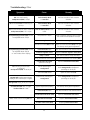
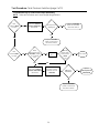
ACTION
Pre-filter inlet/outlet valve closed
CAUSE
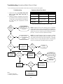
Troubleshooting: NO WATER
Symptoms: No RO water to store, low water pressure
Check RO controller first. The SERVICE REQUIRED light and display will indicate the path to take.
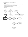
Troubleshooting: Poor Water Quality
Symptoms: Product Quality displayed, poor tasting or cloudy water, scale build-up, Equipment failure
Make sure the water softener brine tank (S5) is filled with salt and that the pre-filter carbon filter cartridges
have not expired (see Test Procedure: Pre-f ilter Cartridges). Hard water and/or chlorine will cause premature
membrane element fouling or damage and affect water quality.
Service Required
light ON?
YES
Product
Quality
displayed?
YES
Change membrane element and
end cap inner O-ring. See Service
Procedure: Membrane Element
Replacement
NO
NO
See Troubleshooting:
No Water
System
bypass
valve (F5) in
bypass?
YES
Put system bypass
valve in normal
position
NO
Open post filter
flush valve (F5) and
flush for 10 minutes*
*
If the RO is operating normally and
the system is not in bypass, the
post filter cartridge may need to
be purged, or TDS has accumulated in the storage tank
Flushing the post filter will purge
the cartridge and drain off the
storage tank.
13
Determine why system
was in bypass position and
correct the underlying problem
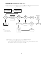
Troubleshooting: Excessive Water Flow to Drain
This is normally a perceive problem rather than an actual issue with the system.
Troubleshooting
Equipment Drain Flow Rates*
1. Make sure that the pre-filter flush valve
(P4) and post filter flush valve (F5) are
both closed.
2. Identify the piece of equipment from which
the excessive flow is suspected. Determine
if flow rate is correct based on the table at
the right listing the component’s normal
flow rates.
Normal Operation
Flush
Softener
0 gpm
2 gpm
Pre-filter
0 gpm
3 to 4 gpm
RO System
0.3 to 0.8 gpm*
3 to 4 gpm
Post Filter
0 gpm
3 to 4 gpm
* Flow should read zero (0) when the RO is IDLE.
Water
softener
drain flow
high?
YES
Replace drain line
flow control (contact
Performance Water for
assistance)
YES
If water is flowing
to drain from RO
replace the inlet solenoid
valve (R5)
NO
RO
IDLE?
NOTE 1: Measure flow rate manually with a graduated
pitcher and a timer. Direct concentrate flow to pitcher for
30 seconds. Note volume and multiply by 2 to determine
gallons per minute. Multiply by 60 to determine gallons
per hour. If rate is incorrect, replace flow meter.
NOTE 2: A small diameter drain line creates a higher
velocity flow which tends to splash and make noise. This
may make normal drain flow seem excessive. Changing
the drain line to a larger diameter and/or rerouting the
drain line to decrease noticeable velocity may help.
NO
RO
Flushing?
Flush drain flow should
be 3 - 4 gpm. Check
normal drain flow
after flush
YES
System
operating
normally
YES
NO
NO
Scroll to
Concentrate Flow
on controller
Flow
normal
during
operation?
Concentrate
Flow < 50
gph?
YES
Manually check
concentrate flow
meter (R24)
(See NOTE 1)
Flow meter
accurate?
NO
Close
concentrate
valve (R13)
NO
YES
Concentrate
Flow
<10 gph?
YES
NO
Note:
“<” means “less than”
‘>” means “greater than”
YES
Flush solenoid valve (R9)
may be stuck open
See Test Procedure: Flush
Solenoid Valve
14
Adjust concentrate
flow rate
See Test Procedure:
System Adjustment
If water is
flowing to drain from
RO replace the inlet
solenoid valve (R5)
Replace
Concentrate Flow
Meter (R24)
Troubleshooting: Other
Symptom
Cause
Remedy
RO runs continuously,
tankpressure (R18 ) > 60 psi
Tank HI Switch (R19)
or controller
See Test Procedure: Tank Pressure
Switches
RO shows Full Tank immediately on
start-up
Tank HI Switch (R19)
or controller
See Test Procedure: Tank Pressure
Switches
RO runs five minutes or less to Tank Full
, tank pressure (R18) = 55 - 65 psi
Tank LO Switch (R17) or controller
See Test Procedure: Tank Pressure
Switches
Pump discharge pressure (R4) cannot
be adjusted below 175 psi
Inlet pressure > 90 psi
Install a pressure reducing valve in supply
line to reduce feed pressure to 60 psi
Pressure regulator valve
Replace Pressure regulator valve (R12)
Concentrate valve (R13) closed
Adjust Concentrate valve (R13) to 45 gph
See Startup and System Adjustment
Flush valve (R9) open
See Test Procedure: Flush Solenoid Valve
Pressure regulator valve
Replace Pressure regulator valve (R12)
Pump or Motor
See Test Procedure: Pump and Motor
Faulty Concentrate Flow Sensor
Replace Concentrate Flow Sensor (R25)
Concentrate valve (R13)
aperture too large
Replace concentrate valve (R13)
Low air precharge in
storage tank
Drain storage tank and adjust air
precharge to 30-35 psi.
Tank valve (T4) closed
Open the Tank valve (T4)
Excessive air precharge in
storage tank
Drain storage tank and adjust air
precharge to 30-35 psi.
System adjusted improperly
See Startup and System Adjustment
Flush valve (R9) open
See Test Procedure: Flush Solenoid Valve
Concentrate flow sensor (R25)
Replace concentrate flow meter
Inlet solenoid valve (R5)
Replace inlet solenoid valve
Product check valve (R16)
Replace product check valve
Pump discharge pressure (R4) cannot
be adjusted above 150 psi
or “Low Product Flow” display
RO runs only 5-10 minutes
to Tank Full,
tank pressure (R18) 45 to 60 psi
When water is drawn from
storage tank, tank pressure drops
rapidly to zero from 40 psi or higher.
Storage tank empty at 40 psi or higher
Concentrate Flow rate < 10 gph,
Product Flow % > 50%
Water flows to drain during RO IDLE
15
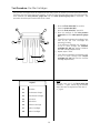
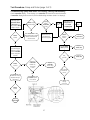
Test Procedure: Pre-filter Cartridges
The pre-filter cartridges should be replaced at least every three (3) months to maintain peak performance.
The filters may clog in less than three months. To test pre-filter cartridge performance, the pressure differential between the inlet pressure gauge (P2) and the outlet pressure gauge (P3) is evaluated. This
procedure should be performed at least once a week.
P2
a.
b.
c.
d.
P3
P1
P5
P4
P7
P6
P8
NOTE:
The flow rate out of the flush valve (P4)
exceeds 4 - 5 gpm, results may be skewed.
Adjust the valve to regulate the flow rate to
4 - 5 gpm.
Legend
P1
Inlet Valve
P2
Inlet Pressure Gauge
P3
Outlet Pressure Gauge
P4
Flush Valve
P5
Outlet Valve
P6
Sediment Cartridge
P7
Carbon Cartridges
P8
Carbon Cartridges
Direct the flush valve (P4) line to drain.
Close the outlet valve (P5).
Open the flush valve (P4). See NOTE.
Note the readings on the inlet pressure
gauge (P2) and the outlet pressure gauge
(P3).
e. If the difference between the readings is less
than 20 psi, the filter cartridges are
operating normally.
f. If the difference between the readings is
20 psi or more, change the sediment
cartridges (P7, P8) (see Service Procedure:
Pre-f ilter Cartridge Replacement).
g. Repeat steps c and d.
h. If the difference between the readings is still
20 psi or more, change both carbon
cartridges (P7, P8) (see Service: Pre-f ilter
Cartridge Replacement).
16
Summary: Inlet and Tank Pressure Switches
Pressure Switch Connection Detail
Pre-filter Outlet
Pressure (P3)
Inlet Pressure Switch (R7)
Result
Switch Closed
Switch Open
Switch Shorted
Switch Broken or Disconnected
0 - 8 psi
> 8 psi
-
Tank HI Pressure Switch (R18)
Tank Pressure (R18)
Switch Open
Switch Closed
Switch Shorted (closed)
Switch Broken or Disconnected
> 60 psi
< 60 psi
> 60 psi
-?-
Tank LO Switch (R17)
Tank Pressure (R18)
Switch Open
Switch Closed
Switch Broken or Disconnected
Switch Shorted (closed)
> 45 psi
< 45 psi
-
RO will not run, low inlet pressure
RO runs
RO will not run, Low Inlet Pressure displayed
RO runs normal, no low pressure protection
Result
Storage tank full, RO Stops
RO IDLE or RUNNING
RO will not turn OFF
Tank Full message at start-up, RO turns ON/OFF
based on tank LO pressure switch (45 psi)
Result
RO IDLE or RUNNING
RO starts
RO will not start, - IDLE (Tank pressure < 45 psi)
RO turns ON/OFF based on Tank Hi pressure
switch (56 - 62 psi)
Switch State Table
Condition
Tank Pressure (R18)
Tank HI (R19)
Tank LO (R17)
Tank Full
IDLE
RO start-up
RUNNING
> 60 psi
45 - 56 psi
< 45 psi
46 - 60 psi
OPEN
CLOSED
CLOSED
CLOSED
OPEN
OPEN
CLOSED
OPEN
Note:
“<” means “less than”
‘>” means “greater than”
17
18
YES
YES
Switch power OFF
and ON (turn OFF
immediately if
pump grinds)
Inlet
pressure switch
operating
normally
Replace
the controller
power circuit
board
NO
Did RO
shut down?
(Low Inlet
Pressure)
Inlet
pressure switch
operating
normally?
NOTE:
To disconnect a inlet pressure switch,
gently pull the wires attached to the switch to
pull the connector through the hole in the
panel. Disconnect the wires, taking care to
ensure the connector does not slip back
through the hole.
Disconnect Inlet
pressure switch
(See NOTE)
See Test
Procedure: Tank
Pressure Switches
RUNNING
or IDLE
displayed?
NO
YES
Switch power
OFF and ON
NO
Low Inlet
Pressure
displayed?
NO
RO
starts?
YES
RO
shut down?
(Low Inlet
Pressure)
Jump controller
terminals 5 & 6 on
header J7 for
6 - 8 seconds
YES
Open post filter
flush valve (F5)
until tank
pressure (R18)
drops < 45 psi
Close pre-filter
outlet valve (P5)
for 8 - 10 seconds
NO
YES
NO
RO
running?
YES
Reconnect
inlet pressure
switch
NO
Pump
pressure (R4)
> 90 psi?
NO
Low Inlet
Pressure
displayed?
Check pre-filters
See Test
Procedure:
Pre-f ilter
Cartridges
Replace
Inlet pressure
switch or repair
wiring
YES
YES
See Test Procedure:
Inlet Solenoid Valve
Replace
Inlet pressure
switch or repair
wiring
Replace the
controller power
circuit board.
Reconnect inlet
pressure switch
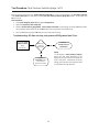
The inlet pressure switch protects the pump from running dry. When pressure is less than 8 psi, the switch closes, removing power to the pump and
inlet solenoid valve.
Before testing, ensure that the system bypass valve (B1) is in normal position, the pre-filter inlet (P1) and outlet(P5) valves are open and that the
pre-filter outlet pressure gauge (P3) reads > 20 psi when the RO is running.
Test Procedure: Inlet Pressure Switch
Test Procedure: Tank Pressure Switches (page 1 of 3)
Before Testing, ensure that the system bypass valve (B1) is in the normal position, the pre-filter inlet (P1)
and outlet valves (P5) are open and that the pre-filter outlet pressure gauge (P3) reads > 20 psi when the
RO is running.
Test Procedure
1. Close tank isolation valve (T2) to bypass storage tank.
2. Open the post filter flush valve (F5).
3. Observe tank pressure gauge (R18). Tank pressure switches are operating normally if RO starts when
tank pressure drops below 55 psi and RO stops when tank pressure exceeds 55 psi.
4. See Troubleshooting steps if RO does not start and stop correctly.
Troubleshooting: RO does not stop, tank pressure (R18) greater than 55 psi
Disconnect tank
pressure switch
(R19)
(See NOTE)
RO stops
Tank Full
displayed?
YES
Replace
tank HI pressure
switch (R19)
NOTE:
To disconnect a tank pressure switch,
gently pull the wires attached to the
switch to pull the connector through the
hole in the panel. Disconnect the wires,
taking care to ensure the connector does
not slip back through the hole.
NO
Replace
controller power
circuit board.
Reconnect switch
19
Test Procedure: Tank Pressure Switches (page 2 of 3)
Troubleshooting: RO starts and stops repeatedly
NOTE: Make sure all valves are in normal operating positions.
Tank
pressure (R18)
> 55 psi?
YES
Disconnect tank LO
pressure switch (R17)
(See NOTE)
RO stops IDLE
displayed?
YES
Replace controller
power circuit board.
Reconnect switch
NO
NO
Replace controller
power circuit board.
Reconnect switch
Tank
pressure (R18)
> 52 psi?
YES
Wires
disconnected in
controller, header
J7, terminals
3&4
NO
Disconnect tank LO
pressure switch (R17)
(See NOTE)
Connect
wires
YES
RO runs,
stops when
tank pressure
(R18)
> 55
YES
Issue resolved
NO
Use wire to jump
terminals 3 & 4 in
controller
RO keeps
RUNNING?
NO
Replace controller
power circuit board.
Reconnect switch
20
YES
Replace
tank HI pressure
switch (R19)
Test Procedure: Tank Pressure Switches (page 3 of 3)
Troubleshooting: RO does not start, tank pressure (R18) less than 45 psi
Wires
disconnected on controller, header J7, terminals 1& 2?
NO
Ensure tank LO pressure
switch (R17) is connected
(See NOTE)
YES
RO keeps
RUNNING?
Connect
wires
Issue resolved
YES
NO
Jump terminals
1 & 2 in controller
with a piece of wire
Does RO
start?
NO
NOTE:
To inspect the tank pressure switch
connector, gently pull the wires attached to
the switch to pull the connector through the
hole in the panel.
Replace
controller power
circuit board
21
YES
Replace
tank LO pressure
switch (R17)
Test Procedure: Inlet Solenoid Valve (Page 1 of 2)
Ensure that system bypass valve (B1) is in the normal position, the pre-filter inlet ({1) and outlet (P5)
valves are open and that the pre-filter outlet pressure gauge (P3) reads > 20 psi when the RO is
running.Low Inlet Pressure is displayed on controller
Open post filter flush
valve (F5) until tank
pressure (R18) drops
<45 psi
Turn RO OFF,
then ON
Low Inlet
Pressure
displayed?
YES
Did water
flow through
system during
start-up?
YES
RO
starts?
Does
pressure
drop below
10 psi?
Observe pre-filter
outlet gauge (P3)
when pump starts
NO
NO
Restart RO and
check for
110 VAC*
* NOTE: Power will
only be on for
three seconds.
May require two
or three tests
YES
110 VAC?
YES
See Test Procedure:
Tank Pressure
Switches
YES
Replace
Inlet solenoid
valve (R5)
YES
Repair wiring
NO
Check for 110 VAC
at controller
header J2,
terminals 3 & 4
110 VAC?
Tank Full
or IDLE
displayed?
Clean or
replace inlet
pressure
switch (R7)
Insert voltage
meter probes
into the two
parallel sockets
Remove DIN
connector from
inlet solenoid
valve (R5)
NO
Inlet solenoid valve
operating normally
YES
NO
Replace controller
power circuit board
22
YES
Replace pre-filters
(See Service
Procedure:
Pre-f ilter Change)
Test Procedure: Inlet Solenoid Valve (Page 2 of 2)
Troubleshooting: RO drains while IDLE
Check for
110 VAC at controller
header J2,
terminals 3 & 4
110 VAC
Replace
controller power
circuit board
YES
NO
Replace inlet
solenoid valve (R5)
23
Test Procedure: Flush Solenoid Valve
In normal operation, when the tank HI pressure switch (R18) reaches 60 psi, the flush solenoid valve (R9) will
open for 20 seconds, performing a flush of the membrane element.
If the flush solenoid valve does not open, it probably will not be noticed in normal operation. However, over
time this will shorten the membrane element life if not corrected.
If the valve does not close, the system drain flow rate will be higher than normal and it will be impossible to
properly adjust the system.
Determining if the flush solenoid valve is opening
After a normal run cycle when the pressure reaches 60 psi, the RO goes into flush mode. The controller will
display Flushing. Scroll to the Concentrate Flow screen. The flow should increase to approximately 160 gph.
If the Concentrate Flow screen does not increase to 160 gph, follow the steps below.
Check for 110VAC
at flush solenoid
valve (R9) DIN
110 VAC?
Replace flush
solenoid valve (R9)
YES
connector
NO
Trace wires
to controller
header J2,
terminals 1 & 2
Connected
correctly?
YES
Check for
110VAC at
terminals
during flush
110VAC?
NO
NO
Correct wiring
Replace controller
power circuit board
YES
Correct wiring
YES
Replace
controller power
circuit board
Troubleshooting: Cannot adjust pump pressure (R4) above 100 psi
Make sure RO is not Flushing before proceeding with troubleshooting
Scroll to Concentrate
Flow on controller
Concentrate
Flow
>10gph?
YES
Close concentrate
valve (R13)
Disconnect DIN
connectors from
flush solenoid
valve (R19)
Concentrate
Flow
>10gph?
YES
Trace wires to
controller
header J2,
terminals 1 & 2
YES
Connected
correctly?
NO
NO
See Test
Procedure: Pump
and Motor
NO
See Test
Procedure: Flush
Solenoid Valve
NO
Rebuild or
replace flush
solenoid valve (R9)
Correct wiring
Reset system See
Test Procedure:
System
Adjustment
24
Test Procedure: Pump and Motor (page 1 of 3)
Caution
Do not allow the pump to run dry as this will damage it (See Test Procedure: Inlet Pressure Switch).
Replace the pump if it is leaking.
Do not tamper with the Safety Relief valve on the side of the pump.
Troubleshooting: Excessive Pump Noise
Test the pump if it is making a squealing or grinding sound. NOTE: the pump will grind momentarily sometimes on start-up.
Pump
noisy, RO
IDLE?
YES
110VAC
at controller
header J2,
terminals
5 & 6?
NO
NO
Turn RO OFF
Replace
controller
motor relay
Disconnect the pump
(R3) from the motor
coupling (R2)
Turn RO OFF
Replace
controller
power circuit board
YES
NOTE: In both of these cases,
the pump generally will need
to be replaced as well
Is the motor
(R1) making
the noise?
YES
Replace motor (R1)
NO
Is the motor
coupling (R2)
coupling
damaged/loose?
NO
Replace pump (R3)
25
YES
Tighten
or replace motor
coupling (R2)
Test Procedure: Pump and Motor (page 2 of 3)
Troubleshooting: cannot adjust pump pressure (R3) above 100 psi.
If RO is not RUNNING, open the post filter flush valve (F5) until RO starts.
Scroll to Concentrate
Flow on Controller
Concentrate
Flow
< 10 gph
YES
Close concentrate valve (R13)
Adjust pressure
regulator valve
(R12) to increase
pump pressure
(R4) to 170 psi
YES
Pump
pressure (R4)
still less than
160 psi?
YES
Motor
coupling
(R2)
broken?
NO
NO
NO
See Test
Procedure: Flush
Solenoid Valve
System
operating normally
Replace
pressure regulator
valve
YES
Replace
motor
coupling (R2)
Pump
pressure
(R4) still <
160 psi?
YES
YES
Reset system
See Test
Procedure
System
Adjustment
Replace
pump (R3)
NO
Note:
“<” means “less than”
‘>” means “greater than”
Reset system
See Test
Procedure:
System
Adjustment
System
operating normally
Troubleshooting: cannot reduce pump pressure (R4) below 170 psi.
Check the Inlet pressure gauge (P3). Pressure should be less than 90 psi.
If greater than 90 psi, install a pressure reduction valve in the supply line before the Water Softener.
If less than 90 psi, replace the Pressure Regulator valve (R12).
26
Test Procedure: Pump and Motor (page 3 of 3)
Troubleshooting: pump and motor not running, running intermittently
Check controller display. If not display, turn controller OFF then ON to reset the breaker.
If controller display does not return, see Troubleshooting: No Water (under “no display”).
If RO is not
Running, open
post filter flush
valve (F5) until
tank pressure (R18)
drops < 45 psi
Motor stops
prematurely?
YES
Motor
starts?
Display
blank
(controller
OFF?)
YES
NO
NO
Determine
what may have caused
earlier overload and
resolve issue
Allow motor to
cool (thermal
overload tripped)
YES
Press manual
operate/engage
button on right
side of controller
motor relay (see
below)
YES
110VAC at
controller
header J2,
terminals
5 & 6?
Replace
controller
motor relay
YES
Motor
stop by
itself?
YES
Turn RO
OFF
Replace
motor (R1)
Rotate pump
(R3) by hand
YES
Replace
motor (R1)
Stiff,
grinds?
YES
Replace
motor (R1)
NO
Line voltage
110VAC or
more?
NO
Check for
110VAC at motor.
Replace wiring if
necessary.
Disconnect the
pump (R3) from
the motor
coupling (R2)
NO
NO
Motor
starts?
Turn RO
OFF
NO
Replace
controller power
circuit board
NO
Have
voltage
corrected
Motor
starts?
NO
Replace
motor (R1)
27
Test Procedure: Membrane Element Production
This test will determine if the output of membrane element is fouled or if the system output meets the minimum requirements of store volume. It is assumed that all other variables have first been eliminated as per
Troubleshooting: No Water.
Controller:
Product Flow
> 15 gph?
YES
24 Hour
Run Time
< 16 Hours?
YES
Daily demand > 320 gpd.
System capacity may need to be
increased.
Notify the site’s facility
management
NO
Increase pump pressure (R4) to
170 psi. See Test Procedure:
System Adjustment
Product Flow
> 15 gph?
YES
Daily demand < 320 gpd.
Additional storage maybe
needed to meet peak demand.
Notify the site’s facility
management
NO
Note:
Product flow rate less than 21gph
with 55°F water (19 gph with 50°F)
indicates that the membrane may
be nearing the end of its useful life.
Problem solved,
Membrane element
now within specifications, check
System Adjustments
NO
Note Product
Flow rate
Turn RO OFF
Close tank
isolation valve
(T4)
Turn RO ON
Manually time
and measure
flow rate
(see NOTE)
Turn RO OFF
Product
Flow
within 10% of
measured
rate?
YES
Replace
membrane element
NO
Replace product
flow meter (R22)
28
Disconnect product
line from tank inlet
(T2). Direct line to a
graduated pitcher.
Reconnect
product line to
tank inlet (T2)
NOTE:
Manually measure flow rate with a
graduated pitcher and a timer.
Direct product flow to pitcher for
30 seconds. Note volume and multiply by 2 to determine gallons per
minute. Multiply gpm by 60 to
determine gallons per hour.
Service Procedure: Pre-filter Cartridge Replacement
1
Tools Required
P2
P3
filter wrench
P1
Materials Required
(supplied with filter
kit, see page 35)
P5
Inlet
Valve
Outlet
Valve
(1) sediment filter
1255744
(2) carbon filters
1225745
O-rings
Food-grade lubricant
*NOTE:
Each filter housing
weighs approximately 15 pounds when
filled with water. Be
prepared to support
this weight when
the housings are
removed. Clean up
any spilled water.
a.
P4
b.
Flush
Valve
4
3
2
Close the inlet valve
(P1) and outlet valve
(P5).
Open the flush valve
(P4) to relieve pressure.
O-ring
Sediment
a.
a.
Loosen filter housings
with the filter wrench.
Unscrew the housings
by hand and remove.*
Discard the old filter
cartridges and
O-rings
b.
c.
b.
c.
Clean and sanitize the
filter housings.
Lightly lubricate a new
O-ring.
Install a new O-ring in
the groove at the top
of each filter housing.
a.
b.
c.
5
6
P4
P5
P2
a.
b.
c.
d.
e.
a.
b.
Ensure flush valve
(P4) is open and tubing is directed to
drain.
Open the inlet valve
(P1).
Flush system for one
minute.
Close the flush valve.
Open the outlet valve
(P5).
c.
29
Check for leaks.
If necessary, tighten
the filter housings
gently using the prefilter wrench
On the controller,
press ENT and ESC
keys for four seconds
to reset the pre-filter
change timer.
Carbon
Install new pre-filter
cartridges in the prefilter housings.
Thread pre-filter
housings back onto
the heads. Note the
correct location of
the pre-filters.
Tighten pre-filter
housings as much as
you can by hand. Do
not over-tighten or use
the pre-f ilter wrench.
Service Procedure: Post filter Cartridge Replacement
1
Tools Required
2
Normal
filter wrench
F4
Bypass
Materials Required
(1) sediment filter
SKU 187200
(2) carbon filters
SKU 187201
O-rings
(supplied with filters)
food-grade lubricant
(supplied with filters)
* NOTE:
Each filter housing
weighs approximately 15 pounds when
filled with water. Be
prepared to support
this weight when
the housings are
removed. Clean up
any spilled water.
F5
a.
F1
F1
Place the system
bypass
valve
in
bypass.
a.
b.
3
4
Close the inlet valve
(F1) and outlet valve
(F4).
Open the flush valve
(P5) to relieve pressure.
5
O-ring
a.
Loosen the filter
housing with the filter
wrench.
Unscrew the housing
by hand and remove.*
Discard the old filter
cartridge and O-ring.
b.
c.
a.
b.
c.
Clean and sanitize filter housing.
Lightly lubricate a new
O-ring.
Install new O-ring in
the groove at the top of
the filter housing.
a.
b.
c.
7
6
F4
F1
a.
b.
c.
d.
e.
F5
a.
b.
Ensure flush water
(F5) and tubing is
directed to drain.
Open the inlet valve
(F1).
Flush system for five
minutes.
Close the flush valve
IF5).
Open the outlet valve
(F4).
30
Check for leaks.
If necessary, tighten
the filter housing gently using the filter
wrench.
Install a new prefilter cartridge in
the filter housing.
Thread filter housing
as much as you can by
hand. Do not overtighten or use the f ilter
wrench.
Tighten filter housing
as much as you can by
hand. Do not overtighten or use the f ilter
wrench.
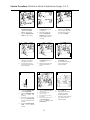
Service Procedure: Membrane Element Replacement (page 1 of 2)
3
2
1
Tools Required
Normal
wrenches
pliers
a
Bypass
22”
Materials Required
membrane element
NOTE:
The membrane element housing weighs
approximately 20
pounds when filled
with water.
Be prepared to support this weight when
the membrane housing is removed. Clean
up any spilled water.
a.
Place the system
bypass valve in
bypass.
a.
4
Turn the RO OFF.
5
a.
Check clearance to left
of housing:
22” or more: proceed
to Step 7a.
Less than 22-inches
proceed to Step 4.
6
b
a
a.
b
Disconnect the tube to
the housing inlet.
Disconnect the two
tubes from the housing
outlets. Note the position of each tube to the
outlets.
b.
7
a.
b
Ask an assistant to
hold up the housing
(housing will drop
when clamps are
undone).
Remove the fasteners
from the clamps holding the housing to the
panel.
b.
8
a.
b.
Remove the housing
from the panel and
place it on the bench,
sink or other flat
surface.
Skip to Step 7b.
9
a
a
b
b
b
a.
b.
Disconnect the tube to
the housing inlet.
Remove the clamp
holding the black plastic end cap to the
housing.
31
a.
b.
c.
Remove the endcap.
Extract the membrane
element from the
housing with pliers.
Discard the membrane element.
a.
b.
Remove the new
membrane element
from its plastic bag.
NOTE: The inlet end of
the membrane element has a black rubber seal (brine seal)
around it.
Service Procedure: Membrane Element Replacement (page 2 of 2)
10
11
12
a
a
b
seal
a.
b.
Insert the end of the
membrane element
opposite of the brine
seal into the housing.
Slide the membrane element into the housing.
13
a.
b.
Use care when inserting
the brine seal to avoid
damaging it.
Resistance will be felt
when the membrane
element mates with the
outlet endcap. Press to
seat fully.
a.
b.
Insert the endcap into the
inlet end of the housing.
Press firmly to overcome
the resistance of the Orings on the endcap.
15
14
a
a
a
a.
b.
Replace the endcap
clamps on the housing
and tighten the bolts.
If the housing was not
removed from the frame,
skip to step 15b.
16
a.
b.
Ask an assistant to hold
the housing in place on
the frame.
Replace the clamps and
secure them with the
bolts.
a.
b.
b
Reconnect the tube to
the housing inlet.
Reconnect the two tubes
to the appropriate
housing outlets.
18
17
c
a
a.
b.
c.
d.
Close the isolation valve
on the storage tank.
Open the post filter valve
(F5) to relieve line
pressure.
Disconnect the product
line at the storage tank
inlet and redirect the line
to drain.
Place the system bypass
valve in the normal
position.
a
a.
b.
c.
d.
d.
e.
f.
Open the concentrate valve
two full turns.
Turn the RO power ON.
Check for leaks.
Run the RO for 20 minutes.
Stop the RO.
Reconnect the product line to
the storage tank inlet.
Open the storage tank
isolation valve.
32
a.
b.
c.
Turn the RO ON.
Adjust system settings.
See Test Procedure:
System Adjustment.
Check the product quality
and confirm that is is
within standard.
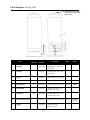
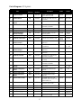
Parts Diagram: Storage Tank
Pre-charge Air pressure
valve stem (under cap)
[30-35 psi]
Part
Manual
Reference
Part
Number
Part Name
Make
1
Bushing
1110314
BUSHING, PVC, MPT x FPT,
0.50 x 0.38
2
Bushing
1110322
BUSHING, PVC, FPT x PVC,
1.00 x 0.50
3
Elbow
1110360
ELBOW-90, FPT,PVC, 1.00
4
Tee
1110404
TEE, PVC, FPT, 0.50
5
Storage Tank
T1
1235146
TANK, STORAGE, PP, 30 GAL RO mate
6
Tank Outlet
T3
1237107
CONNECTOR, MPT x TB,
ACETAL, 0.50 x 0.50
7
Tank Inlet
T2
1237108
ELBOW, FIXED, MPT x TB,
ACETAL, 0.38 x 0.38
8
Tank Isolation Valve
T4
1244357
VALVE-BALL, PVC, 0.50 FPT
9
Nipple
1255436
NIPPLE, MPT, NYL,
0.50 x CLS, HEX
33
SMC
Model
30853
PVC-6388F8F-B
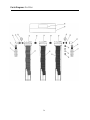
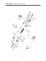
Parts Diagram: Pre-Filter
34
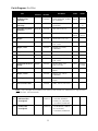
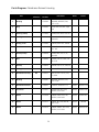
Parts Diagram: Pre-Filter
Part
Manual
Reference
Part
Number
Part Name
Make
Model
GX04-20
1
Sediment Filter
Cartridge
1255744*
FILTER, SEDIMENT, HYTREX,
20”, 5 MICRON
Hytrex
2
Carbon Filter
Cartridge
1255745*
CARTRIDGE, CARBON, 20”,
10 MICRON
Sta-rite F10-25020
3
Filter/Housing/Head
Assembly
P6, P7, P8
1255746
HSG, PRE-FILTER, 20”
Pentair
158205
4
Inlet/Outlet Valve
P1, P5
1255747
INLET/OUTLET VALVE
MatcoNorca
VMATPBV155
5
Nipple
1255748
VALVE-BALL, PVC, 0.75”
6
Elbow
1255749
NIPPLE, NYLON,
0.75” x 0.50”
7
Nipple, 1 Port
1255751
ELBOW, 0.50”, PORT,
CHR/BRASS
8
Nipple
1255757
NIPPLE, 0.50”, CHROME
9
Flush Valve
1255758
VALVE-BALL, PVC, 0.25”
SMC
6380090
10
Connector
1255759
CONNECTOR, MPT X TB,
0.38” x 0.25”
11
Inlet/Outlet Pressure
Gauge
1255762
GAUGE, PRESS, 1.50”
DIAL./125 PORT
Span
SPAN101
D-158E
12
Nipple
1255763
NIPPLE, 0.50”, CHROMEBRASS
13
Nipple, 2 Ports
1255764
NIPPLE, 0.50”, PORTS,
CHR/BRASS
14
Housing Bracket
1255693
BRACKET, HOUSING, PREFILTER
15
Pre-filter NSF Label
1255694
LABEL, NSF42, PRE-FILTER
*
P4
P2, P3
NOTE: Filter cartridges are available as four-pack kits that include four replacement O-rings and food
grade lubricant. GE recommends:
1
Sediment Filter
Cartridge Kit
1244712
4 X FILTER, SEDIMENT,
HYTREX, 20”, 5 MICRON,
4 X O-RINGS, LUBRICANT
2
Carbon Filter
Cartridge Kit
1244713
4 X CARTRIDGE, CARBON,
20”, 10 MICRON,
4 x O-RINGS, LUBRICANT
35
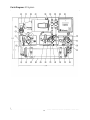
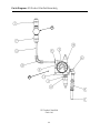
Parts Diagram: RO System
36
Parts Diagram: RO System
Part
Manual
Reference
Part
Number
1237107
1
Inlet Connector
2
Inlet Solenoid
R5
1235081
3
Inlet Pressure Switch
(8 psi)
Inlet Manifold
R7
1239726
R6
1255150
Motor
Pump
Pump Discharge
Pressure Gauge
Membrane Housing
Product Check Valve
R1
R2
R4
1226456
1237106
1113393
R8
R16
1162152
1235086
Tank LO Pressure
Switch (45 psi)
Tank Pressure Gauge
R17
1239727
R18
1118571
R19
1239728
13
Tank HI Pressure
Switch (60 psi)
Conductivity Sensor
R14
1237117
14
Product Manifold
R15
1255150
15
Flush Solenoid Valve
R9
1235081
16
Concentrate Manifold
R10
1255150
17
R11
1113393
R12
1235089
R13
R25
1237674
1237118
21
Concentrate Pressure
Gauge
Pressure Regulator
Valve
Concentrate Valve
Concentrate Flow
Meter
Concentrate Outlet
R24
1237116
22
Product Outlet
R23
1237116
23
24
25
26
27
Product Flow Meter
Controller
Backpanel
Motor Coupling
PVC Tube
R22
R21
1237118
1237248
1237128
1119529
1237115
4
5
6
7
8
9
10
11
12
18
19
20
R2
37
Part Name
Make
Model
INLET CONNECTOR,
(0.5” MPT x 0.5” TB)
VALVE-SOL, BRS, 0.5, FPT,
120 VAC
INLET PRESSURE SWITCH
Parker
A8MC8-MG
MANIFOLD, FLOW-BLOCK,
WM-800, MOLDED
PUMP MOTOR
PUMP
GAUGE, PRESS, 2.5, PSI,
300 SS, BACK
HOUSING
VALVE-CHK, ACETAL, 0.38
Burkert
456-540C
Nason
Marathon 56C17D5916
Procon
ENFM
John
Guest
Nason
PRODUCT LOW PRESSURE
SWITCH
GAUGE, PRESS, 316, 2.5, PSI, ENFM
160, BACK
PRODUCT HIGH PRESSURE
Nason
SWITCH
PRODUCT CONDUCTIVITY
SENSOR
MANIFOLD, FLOW BLOCK,
WM-800, MOLDED
VALVE-SOL, BRS, 0.5, FPT,
Burkert
120VAC
MANIFOLD, FLOW BLOCK,
WM-800, MOLDED
GAUGE, PRESS, 2.5, PSI, 300, ENFM
SS, BACK
PRESSURE REGULATOR
SMC
VALVE
CONCENTRATE VALVE
CONCENTRATE FLOW
METER
CONNECTOR, FPT x TB,
Parker
ACETAL, 0.50” x 0.38” HSG,
PRE-FILTER, 20”
CONNECTOR, FPT x TB,
Parker
ACETAL, 0.50 x 0.38
PRODUCT FLOW METER
ELECTRICAL ENCLOSURE
PANEL
PUMP ADAPTER
Procon
PVC TUBING
Accuflex
(0.5” ID, 0.75” OD)
#7229,
0-300
3/8SCV
#7229;
0 - 160
456, 540 C
#7229;
0 - 300
555
A6FC8-MG
A6FC8-MG
1048-1C
K6158-08
5
8
16
14
1
2
8
3
7
6
9
10
5
7
3
6
11
13
8
8
7
10
9
11
7
6
4
12
17
15
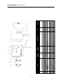
Parts Diagram: Membrane Element Housing
38
Parts Diagram: Membrane Element Housing
Part
Manual
Reference
Part
Number
Part Name
Make
Model
1
Bushing
1110269
BUSHING, MPTXFPT, 304,
0.75 x 0.50
2
Plug
1110455
PLUG, PIPE, MPT, NYL, SQH,
0.50
3
Housing Clamp
1111640
CLAMP, PIPE, GALV, 4.25 OD
4
Bushing
1115482
BUSHING MPTXFPT, 304,
0.50X0.25
5
O-Ring, Inner
1151580
O-RING, EPDM 116, 70DUR
6
Hex Nut
1154925
NUT, HEX, NYLOCK,M 18-8,
031- 18C
7
Endcap Clamp
1158328
CLAMP, HALF, 4.0, FL, SS,
300 PSIG
8
Bolt
1158446
SCREW, CAP, HH, 18-8, 0.3118 x 1.25
9
Endcap
1158620
ENDCAP, SH, 4.0, FL, GFN, EE
10
O-Ring, Outer
1159957
O-RING, EPDM, 342, 70DURO
11
Membrane Housing
1162152
HSG, SH-1/4 X 21-DC, 316,
FL, UNPK
12
Bushing
1203391
BUSHING, MPTXFPT, 316,
0.75 X 0.38
13
Membrane Element
1206812
ELEMENT, AK4051T1773
Desal
AK4021T1773
14
Connector
1237107
CONNECTOR, MPT X TB,
ACETAL, 0.50 X 0.50
Parker
A8MC8-MG
15
Elbow
1237108
ELBOW, FIXED, MPT S TB,
ACETAL, 0.38 X 0.38
Parker
A6ME6-MG
16
Elbow
1237112
ELBOW, TB X HSB, ACETAL,
0.50 X 0.50
Parker
A8TEB8
17
Elbow
1237114
ELBOW, SWIVEL, MPT X TB,
ACETAL, 0.25 X 0.38
Parker
A6MES4-MG
R8
39
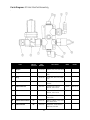
Parts Diagram: RO Inlet Manifold Assembly
Part
Manual
Reference
Part
Number
Part Name
Make
Model
1
Nipple
1110379
NIPPLE, PVC, MPT, 0.50 XCLS
2
Plug
1110455
PLUG, PIPE, MPT, NYL, SQH,
0.50
3
Plug
1110519
PLUG, PIPE, MPT, NYL, SQH,
0.25
4
Inlet Solenoid Valve
1235081
VALVE-SOL, BRS, 0.5, FPT,
120VAC
Burkert
456 540 C
5
Inlet Connector
1237107
CONNECTOR, MPXTB,
ACETAL, 0.50 x 0.50
Parker
A8MC8-MC
6
Elbow
1237108
ELBOW, FIXED, MPT x tB,
ACETAL, 0.38 x 0.38
Parker
A6ME6-MB
7
Elbow
1237112
ELBOW, TB x HSB, ACETAL,
0.50 x 0.50
Parker
A8TEB8
8
Inlet Pressure Switch
R7
1239726
SWITCH, PRESS, 8 PSI, NONADJ, WITH PLUG
9
Inlet Manifold
R6
1255150
MANIFOLD, FLOW-BLOCK,
WM-800, MOLDED
R5
41
Parts Diagram: RO Concentrate Manifold Assembly
42
Parts Diagram: RO Concentrate Manifold Assembly
Part
Manual
Reference
Part
Number
Part Name
Make
Model
1
Nipple
1110154
NIPPLE,BRS, MPT, 0.25 X CLS
2
Bushing
1110314
BUSHING, PVC, MPT X FPT,
0.50 x 0.38
3
Nipple
110376
NIPPLE, MPT, PVC, 0.38 X CLS
4
Nipple
1110379
NIPPLE, MPT,PVC, 0.5 X CLS
5
Plug
1110455
PLUG, PIPE, MPT, NYL, SQH,
0.50
6
Concentrate Pressure
Gauge
1113393
GAUGE, PRESS, 2.5 PSI, 300
SS, BACK
ENFM
A6ME6-MB
7
Tube
1226629
TUBE, POLYETHYLENE, 0.38,
WHITE
John
Guest
PE-12 El0500F-W
8
Flush Solenoid Valve
R9
1235081
VALVE-SOL, BRS, 0.5, FPT,
120VAC
Burkert
456 540 C
9
Pressure Regulator
Valve
R12
1235089
VALVE-REG, PRESS, BRS, 0.38
SMC
555
10
Elbow
1237108
ELBOW, FIXED, MPT X TB,
ACETAL, 0.38 x 0.38
Parker
A6ME6-MG
11
Tee
1237111
TEE, SWIVEL, TB X MPT X TB,
ACETAL, 0.38 x 0.38
Parker
A6MRS4-MG
12
Connector
1237113
CONNECTOR, MPT X TB,
ACETAL, 0.38 x 0.38
Parker
A6MC6-MG
13
Connector
1237116
CONNECTOR, FPT X TB,
ACETAL, 0.50 x 0.38
Parker
A6FC8-MG
14
Concentrate Valve
1237674
VALVE-NEEDLE, BRS, FPT,
0.25, 11 GPH
15
Bend Clip
1237723
FITTING, CLIP, FLOW BEND,
0.38-INCH
John
Guest
PM2610S
16
Concentrate Manifold
1255150
MANIFOLD, FLOW-BLOCK,
WM-800, MOLDED
17
Concentrate
Flow Meter
1237118
CONCENTRATE FLOW METER
R11
R25
43
Parts Diagram: RO Product Manifold Assembly
12
13
RO Product Manifold
Parts List
44
Parts Diagram: RO Product Manifold Assembly
Part
Manual
Reference
Part
Number
Part Name
Make
Model
1
Bushing
1110312
BUSHING, PVC, MPT x FPT,
0.50 x 0.25
2
Bushing
1110314
BUSHING, PVC, MPT x FPT,
0.50 x 0.38
3
Tank Pressure Gauge
1118571
GAUGE, PRESS, 316, 2.5,
PSI,160, BACK
ENFM
7229; 1-160
4
Tube
1226617
TUBE, POLYETHYLENE, 0.38,
BLUE
John
Guest
PE-12-El0500F-B
5
Product Check Valve
1235086
VALVE-CHK, ACETAL, 0.38
John
Guest
3/8SCV
6
Elbow
1237108
ELBOW, FIXED, MPT x TB,
ACETAL, 0.38 x 0.38
Parker
A6ME6-MG
7
Product Outlet
1237116
CONNECTION, FPT x TB,
ACETAL, 0.50 x 0.38
Parker
A6FC8-MG
8
Bend Clip
1237723
CONDUCTIVITY SENSOR
FITTING, CLIP, FLOW BEND,
0.38”
John
Guest
PM2610S
9
Tank LO Pressure
Switch (45 psi)
R17
1239727
SWITCH, PRESS, 45 PSI,
NON-ADJ, WITH PLUG
10
Tank HI Pressure
Switch (60 psi)
R19
1239728
SWITCH, PRESS, 60 PSI,
NON-ADJ, WITH PLUG
11
Product Manifold
R15
1255150
MANIFOLD, FLOW-BLOCK,
WM-800, MOLDED
12
Product Flow Meter
R22
1237118
PRODUCT FLOW METER
13
Conductivity Sensor
R14
1237117
CONDUCTIVITY SENSOR
R18
R16
R23
45
46
Display Circuit Board
Power Circuit Board
Transformer
Power Relay
Panel Circuit Breaker
Circuit Breaker
2
3
4
5
6
Part
1
6
Manual
Reference
DISPLAY CIRCUIT BOARD
POWER CIRCUIT BOARD
TRANSFORMER
POWER RELAY
PANEL
CIRCUIT BREAKER
1240001
1237845
1239504
1237251
1237252
Part Name
1240000
Part
Number
Make
Model
Parts Diagram: RO Controller assembly
1
2
3
4
5
6
7
8
9
47
Concentrate Flow Sensor
Product Flow Sensor
Conductivity Sensor
Enclosure
Hinge Kit
Label
Power Switch
Connector
Cord
Part
R20
R24
R14
R25
Manual
Reference
Part Name
CONCENTRATE FLOW SENSOR
PRODUCT FLOW SENSOR
CONDUCTIVITY SENSOR
ENCLOSURE
HINGE KIT
LABEL
SWITCH
CONNECTOR
CORD
Part
Number
1237118
1237118
1237117
1237249
1237122
1237123
1237252
1201667
1113729
Make
Model
Parts Diagram: RO Controller
Parts Diagram: Post Filter assembly
PF-110 Post-Filter & Re-Mineralizer Assembly
Parts List
48
Parts Diagram: Post Filter assembly
Part
Manual
Reference
Part
Number
Part Name
Make
Model
1
Bushing
1110314
BUSHING, PVC, MPT x FPT,
0.50 x 0.38
2
Tee
1110404
TEE, PVC, FPT, 0.50
3
Pipe Plug
1110455
PLUG, PIPE, MPT, NYL, SQH,
0.50
4
Connector
1237107
CONNECTOR, MPT x TB,
ACETAL, 0.50 x 0.50
Parker
A8MC8-MG
5
Connector
1237113
CONNECTOR, MPT x TB,
ACETAL, 0.38 x 0.38
Parker
A8MC8-MG
6
Inlet/Outlet/Flush
Valve
1244357
VALVE-BALL, PVC, 0.50 FPT
SMC
6389390
7
Nipple
1255436
NIPPLE, MPT, NYL, 0.50 x
CLS. HEX
8
Housing/Head
Assembly
1261327
HSG, POST FILTER, 10”
SMC
PVC-6388F8F-B
9
Carbon/Calcite
Filter Cartridge
1261328
CARTRIDGE, CARBON/
CALCITE, 10”
10
Bushing
1261329
BUSHING, PVC, MPT x FPT,
1” x 0.50”
11
Post filter Pressure
Gauge
1261330
GAUGE, PRESS, 2.00”
DIAL/0.25” PORT
Catp
PMB204
ELME
12
Bushing
1261331
BUSHING, PVC, MPT x FPT,
0.50” x 0.25”
13
Housing Bracket
1261352
BRACKET, HOUSING,
POST FILTER
14
Nipple
1261353
NIPPLE, 0.50”
F1, F4, F5
F2
F3
49
Return Goods Authorization (RGA) Procedure
If you wish to return goods for repair, warranty evaluation and/or credit, please have your original
sales order or invoice available when you call GE. Call (800) 848-1750 and you will be prompted to the
correct Customer Service Representative.
Please be prepared to provide the Model number:______________________
and Serial number:______________________
of the product being returned.
(Model and Serial numbers are listed on the label attached to the product.
GE Infrastructure telephone prompts:
2
3
A GE Customer Service Representative
All equipment GE Representative
A GE Customer Service representative will provide instructions and a Returned Goods Authorization
number (RGA #), which needs to be clearly written on the outside of the box used to ship your materials. All equipment must be shipped to GE with the freight prepaid by the customer. Call our Customer
Service Center with any questions or issues concerning freight claims and a representative will discuss
your situation.
All materials to be returned must be rendered into a non-hazardous condition prior to shipping.
Ship-to address:
GE Osmonics, Inc.
5951 Clearwater Drive
Minnetonka, MN 55343 USA
Attn: RGA#________________
50
Warranty: BEV-RITE
Warranty Terms
Subject to the terms and conditions set forth hereinafter, Seller (GE Osmonics, Inc. or any of its authorized subsidiaries) warrants to the original purchaser (hereafter the “Buyer”) that the products manufactured by Seller are free from defects in material and in workmanship for twelve (12) months from
the Warranty Commencement Date (as defined below) only when used strictly in accordance with the
applicable operating instructions and within the range of the operating and maintenance conditions
specified in this Service manual. This Warranty does not extend to equipment or components manufactured by others into which a Seller product has been incorporated or to equipment or components
which have been incorporated into a Seller product but, if allowable, Seller hereby assigns, without
warranty, to the Buyer its interest, if any, under any warranty made by the manufacturer of such
equipment or component. This Warranty does not cover disposable items such as fuses, lamps, filters,
cartridges, or other such disposable items, which must be replaced periodically under the normal and
foreseeable operating conditions of the goods warranted hereby.
Warranty Commencement Date
The Warranty Commencement Date for each Seller product shall be the later of the date of: (1) receipt
by the Buyer, or (2) the date of installation at the Buyer’s premises provided that such installation must
occur within three (3) months of shipment from the Seller’s manufacturing facility in Minnetonka,
Minnesota. In no event shall the Warranty Commencement Date exceed three (3) months from the
shipment from the Seller’s manufacturing facility. The Buyer shall provide proof of purchase in order
to exercise rights granted under this Warranty. If requested by GE Osmonics, the Buyer must also provide proof of the installation date. Proof of installation shall be returned by Buyer to Seller within thirty (30) days after installation by virtue of supplying a Warranty Validation Card supplied with each
Seller product fully completed and signed in ink by Buyer and the authorized installer of the product.
Warranty Service
SELLER’S OBLIGATION UNDER THIS WARRANTY IS LIMITED TO REPAIR OR REPLACEMENT (AT SELLER’S
SOLE OPTION) OF ANY PRODUCT, OR COMPONENT THEREOF, PROVED TO BE DEFECTIVE IN MATERIAL OR
WORKMANSHIP WITHIN THE COVERED WARRANTY PERIOD. The Buyer. at the Buyer’s risk and expense,
shall be responsible for returning such product or component, upon obtaining a Return Goods
Authorization (RGA) number from the Seller, freight prepaid, and in conformance with any special packaging and shipping instructions set forth on the operation documentation or RGA instructions, or as
otherwise reasonably required, to the Seller’s address set forth below, together with
(1) RGA number issued by Seller at Buyer’s request;
(2) Proof of purchase and, if necessary, proof of installation date;
Note: The original Purchase Order number, or a copy of the signed Warranty Validation card will be
considered proof of purchase and installation.
(3) a description of the suspected defects;
(4) the serial number of the Seller product alleged to be defective; and
(5) a description of the type of water pretreatment equipment which has been utilized in connection
with the product, if any.
51
Warranty: BEV-RITE (cont’d)
Seller shall, in Seller’s reasonable discretion, be the sole judge of whether a returned product or component is defective in material or workmanship. Products or components to be repaired or replaced
shall be returned to the Buyer by the Seller, freight prepaid by Seller, via UPS ground or best way surface freight. In genuine emergency situations, Seller will (at Seller’s sole option) forward replacement
parts to Buyer without waiting for authorized return of the questionable part(s). In such cases, Buyer
will issue a purchase order or other payment guarantee prior to shipment. If the returned product is
found to be defective, the Buyer’s account will be credited for the full purchase price. If the returned
item is found to have been misused or abused, or the defective part is not received by Seller within thirty (30) days, the Buyer will be invoiced for the replacement part(s) provided. This Warranty does not
cover or include labor and/or travel to the Buyer’s premises or any other location. Charges will be
made for the usual and customary Seller costs and associated expenses incurred by Seller in providing Warranty Service at any location other than Seller’s factory at the address set forth below, and
Seller reserves the right to precondition such travel to Buyer’s premises upon prepayment of Seller’s
anticipated costs of attending such premises.
Voidability of Warranty
This Warranty shall be void and unenforceable as to any Seller product which has been damaged by
accident, mishandling, abuse or has been repaired, modified, altered, disassembled or otherwise
tampered with by anyone other than Seller or an authorized Seller service representative; or, if any
replacement parts are not authorized by Seller have been used, or, the product has not been installed,
operated and maintained in strict accordance and adherence with the operating documentation and
manuals for such product. Any express warranty, or similar representation of performance set forth in
the operation documentation for a reverse osmosis or ultrafiltration membrane incorporated into a
Seller product shall be void and unenforceable unless the feed water requirements set forth in the
operating documentation for such product are unequivocally and strictly adhered to.
Limitations and Exclusions
THIS WARRANTY AND REMEDIES DESCRIBED HEREIN AND HEREINABOVE ARE EXCLUSIVE AND IN LIEU OF
ANY AND ALL OTHER WARRANTY OR REMEDIES, EXPRESSED OR IMPLIED, INCLUDING WITHOUT
LIMITATION, ANY IMPLIED WARRANTY OF MERCHANTABILITY OR FITNESS FOR A PARTICULAR PURPOSE.
IN NO EVENT SHALL THE SELLER BE LIABLE FOR ANY CONSEQUENTIAL, INCIDENTAL OR OTHER SIMILAR
TYPES OF DAMAGES, OR FOR DAMAGES FOR THE LOSS OF PRODUCTION OR PROFITS, OR INJURY TO PERSON OR PROPERTY. NO PERSON HAS ANY AUTHORITY TO BIND SELLER TO OTHER THAN WHAT IS SET
FORTH ABOVE.
THIS WARRANTY GIVES THE BUYER SPECIFIC LEGAL RIGHTS AND THE BUYER MAY ALSO HAVE OTHER
RIGHTS WHICH VARY FROM JURISDICTION TO JURISDICTION. THE PARTIES RECOGNIZE AND AGREE,
THAT IN ALL RESPECTS THE LAWS OF THE STATE OF MINNESOTA SHALL APPLY TO AND SHALL GOVERN
ANY INTERPRETATION OR LEGAL SIGNIFICANCE OF THIS DOCUMENT.
52
Maintenance Logs: Routine Maintenance Log
Routine Maintenance
Daily
Operator checks water softener brine tank (S5) and add salt if less than 1/4 full.
Operator checks pre-filter pressure differential and replaces pre-filter cartridges as needed.
Every 3 Months
Maximum time between replacement of sediment filter cartridge and carbon filter cartridges.
Every 9 - 12 Months
Replace post filter remineralization cartridge.
Minimum 4 times per Year (quarterly)
Check system adjustments.
Test product water for compliance with specifications as stated in this manual
Every 2 - 3 Years
Replace membrane element.
Routine Maintenance Log
NOTE: Record Filter and membrane element changes during routine maintenance in log below.
Date
Brine Tank
Full (Y/N)?
Last sediment
filter change
Last carbon filter
change
NOTE: This is a template, make copies as needed.
53
Last post filter
change
Last membrane
element change
Maintenance Logs: Routine Maintenance Schedule
Maintenance Log
Use this Maintenance Log at each maintenance visit for the RO system. Note settings of RO on every service
visit to help track performance of system. Note settings while RO system is running normally.
RO Serial Number:
Pre-filter Serial Number:
Date/Time
Technician
Initials
Pre-filter, Outlet
Pressure (psi)
Product Flow
(GPH)
Concentrate
Flow (GPH)
Product Quality
(PPM, TDS)
24 Hour
Product GAL
24 Hour Run
Time HR
Filter Change
Due HOURS
Run Hours HOURS
Total Product
(GAL)
Pump pressure
(psi)
Concentrate
pressure(psi)
Tank pressure
psi, RO starts
Tank Pressure
psi, RO stops
NOTE: This is a template, make copies as needed.
54
Global Headquarters
Trevose, PA
+1-215-355-3300
Americas
Minnetonka, MN
+1-952-933-2277
1-800-848-1750
Europe/Middle East/Africa
Heverlee, Belgium
+32-16-40-20-00
Asia/Pacific
Shanghai, China
+86-21-5298-4573
Visit us online at www.gewater.com
*Trademark of General Electric Company; may be registered in one or more countries
© 2004, General Electric Company. All rights reserved.
P/N 1264060 Rev A