1
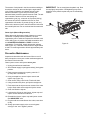
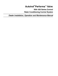
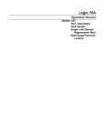
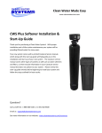
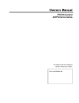
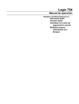
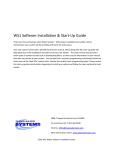
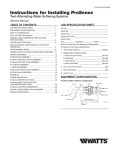
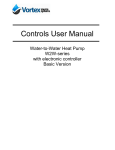
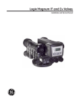
Autotrol® 255 Valve / 400 Series Controls
Water Conditioning Control System
Home Owner Installation, Operation and Maintenance Manual
For sales or service questions please
contact your local dealer:
Your Local Dealer Is:
•
ED
AND CERT
I
DS
D
FIE
AR
IN
DU
D
The 255 water conditioner’s control
valve conforms to NSF/ANSI 44 and 61
for materials and structural integrity only.
Generic systems were tested and
certified by WQA as verified by the
performance data sheet.
ER
2
3
4
4
6
7
16
16
17
17
18
U ND
Safety Information
Valve Illustration
System Regeneration Cycles
Installation
Disinfection of Water Conditioners
Placing Conditioner into Operation
Troubleshooting
Valve Troubleshooting
255/440i Troubleshooting
255/460i/460TC Troubleshooting
Valve Specifications
Safety Information
TES
T
Table of Contents
A
STR Y ST
N
Please review this entire Installation and Operation
manual before installing unit.
• We recommend that this water conditioning unit be
installed by a trained professional water treatment
dealer. Follow all local codes for plumbing this unit.
• Follow local electrical codes. Install a correctly sized
electrical bonding jumper between the inlet and outlet
pipes when these devices are installed in metallic
plumbing systems.
• Inspect this unit carefully for carrier shortage or
shipping damage before beginning installation of unit.
• This system is not intended to be used for treating
water that is microbiologically unsafe or of unknown
quality without adequate disinfection before or after the
system.
• This system is to be used only for potable water.
• Use only lead-free solder and flux, as required by
federal and state codes, when installing soldered
copper plumbing.
• Use caution when sweat joining metal pipes near this
water conditioning system. Heat can adversely affect
the plastic used in this system and bypass valve.
• Use only silicone grease for lubrication of this unit.
• Use only the power transformers supplied with this
conditioning systems control valve unit.
• Do not allow this water conditioning unit to freeze.
Damage from freezing will void this water conditioning
unit’s warranty.
• Do not store flammable or volatile chemicals near this
water conditioning unit.
• For the purpose of plumbing system sizing, only the
rated service (i.e. "Normal") flow and corresponding
pressure loss may be used. The rated service flow
rates are the flow rates at which the performance
capabilities of these devices were evaluated.
Contact your local Professional Water Dealer for system
service, and to obtain Autotrol replacement parts for this
control valve unit.
2
Valve Illustration
Autotrol 255 Valve Control Module
400 Series Control
Optional i-lid Cover
Variable
Brine Control
Air Check
Injector Access Plug
Figure 1
Tank Adapter Module
Optional Bypass
B Y PA S S
Brine Line Fitting Connection
1/4-inch NPT
B Y PA S S
Air Check
Probe Connection Slot
Inlet Connection 3/4-inch
or 1-inch NPT or BSPT
Drain Connection 3/8-inch
or 1/2-inch NPT or BSPT
Outlet connection 3/4-inch
or 1-inch NPT or BSPT
Tank Thread 2-1/2-inch - 8 male
Figure 2
3
System Regeneration Cycles
1.
Service (Downflow):
The resin is regenerated during the brine cycle. Brine
draw is completed when the air check closes.
Untreated water is directed down through the resin bed
and up through the riser tube. The hardness ions
attach themselves to the resin and are removed from
the water. The water is conditioned as it passes
through the resin bed.
2.
4.
The control directs water down through the resin bed
and up through the riser tube to the drain. Any
remaining brine residual is rinsed from the resin bed.
Backwash (Upflow):
5.
The flow of water is reversed by the control valve and
directed down the riser tube and up through the resin
bed. During the backwash cycle, the bed is expanded
and debris is flushed to the drain.
3.
Fast Rinse (Downflow):
Brine Refill (Downflow):
Brine refill occurs during a portion of the fast rinse
cycle. Water is directed to the regenerant tank at a
controlled rate, to create brine for the next
regeneration.
Brine/Slow Rinse (Downflow):
The control directs water through the brine injector and
brine is drawn from the regenerant tank. The brine is
then directed down through the resin bed and up
through the riser tube to the drain. The hardness ions
are displaced by sodium ions and are sent to the drain.
6.
Repressurize Cycle — (No Flapper Open), :
This cycle closes all flappers for a short time to allow
the air and water to hydraulically balance in the valve
before continuing the regeneration.
To Regenerant
Tank
From Regenerant
Tank
SERVICE
BACKWASH
REPRESSURIZE
BRINE/SLOW RINSE
Figure 3
FAST RINSE
BRINE REFILL
d
Installation
heat back down the cold pipe into the unit control valve.
Hot water can severely damage the conditioner. A 10foot (3-m) total pipe run, including bends, elbows, etc.,
is a reasonable distance to help prevent this possibility.
A positive way to prevent hot water from flowing from
heat source to the conditioner, in the event of a
negative pressure situation, is to install a check valve in
the soft water piping from the conditioner. If a check
valve is installed, make certain the water heating
unit is equipped with a properly rated temperature
and pressure safety relief valve. Also, be certain
that local codes are not violated.
All plumbing must conform to local codes.
Inspect unit carefully for carrier shortage or shipping
damage.
Location Selection
1. The distance between the unit and a drain should be as
short as possible.
2. If it is likely that supplementary water treating
equipment will be required, make certain adequate
additional space is available.
3. Since salt must be added periodically to the brine tank,
the location should be easily accessible.
5. Do not locate unit where it or it’s connections (including
the drain and overflow lines) will ever be subjected to
room temperatures under 34oF (1oC) or over 120oF
(49oC).
4. Do not install any unit closer to a water heater than a
total run of 10 feet (3 m) of piping between the outlet of
the conditioner and the inlet to the heater. Water heaters
can sometimes overheat to the extent they will transmit
6. Do not install unit near acid or acid fumes.
4
4. Where the drain line is elevated but empties into a drain
below the level of the control valve, form a 7-inch (18cm) loop at the far end of the line so that the bottom of
the loop is level with the drain line connection. This will
provide an adequate siphon trap.
7. The use of resin cleaners in an unvented enclosure is
not recommended.
Water Line Connection
The installation of a bypass valve system is recommended
to provide for occasions when the water conditioner must
be bypassed for hard water or for servicing.
5. Where the drain empties into an overhead sewer line, a
sink-type trap must be used.
®
The most common bypass systems are the Autotrol
Series 256 bypass valve (Figure 4) and plumbed-in globe
valves (Figure 5). Though both are similar in function, the
256 Autotrol bypass offers simplicity and ease of operation.
Not in Bypass
IMPORTANT: Never insert drain line into a drain, sewer
line or trap. Always allow an air gap between the drain line
and the wastewater to prevent the possibility of sewage
being back-siphoned into conditioner.
In Bypass
Right WayCorrect Way
Drain Line Tube
BY
PA S S
BY
PA S S
BY
BY
PA S S
PA S S
Drain
Figure 6
Figure 4 Autotrol Series 256 Bypass Valve
Not in Bypass
Note: Standard commercial practices have been
expressed here. Local codes may require changes to these
suggestions.
In Bypass
Brine Line Connection
It will be necessary to install the brine tube and line to a
fitting installed on the air check. Teflon1 tape all threaded
connections.
Water
Conditioner
Be sure all fittings and connections are tight so that
premature checking does not take place. Premature
checking is when the ball in the air check falls to the bottom
before all brine is drawn out of the brine tank. See Placing
Conditioner into Operation section.
Water
Conditioner
Figure 5 Typical Globe Valve Bypass System
Overflow Line Connection
Drain Line Connection
1. Ideally located, the unit will be above and not more than
20 feet (6.1 m) from the drain. For such installations, use
an appropriate adapter fitting (not supplied), to connect
1/2-inch (1.3-cm) plastic tubing to the drain line
connection of the control valve.
In the absence of a safety overflow and in the event of a
malfunction, the BRINE TANK OVERFLOW will direct
“overflow” to the drain instead of spilling on the floor where
it could cause considerable damage. This fitting should be
on the side of the cabinet or brine tank.
2. If the unit is located more than 20 feet (6.1 m) from
drain, use 3/4-inch (1.9-cm) tubing for runs up to 40 feet
(12.2 m). Also, purchase appropriate fitting to connect
the 3/4-inch tubing to the 1/2-inch NPT drain
connection.
To connect overflow, locate hole on side of brine tank.
Insert overflow fitting (not supplied) into tank and tighten
with plastic thumb nut and gasket as shown (Figure 7).
Attach length of 1/2-inch (1.3-cm) I.D. tubing (not supplied)
to fitting and run to drain. Do not elevate overflow line
higher than 3 inches (7.6 cm) below bottom of overflow
fitting. Do not tie into drain line of control unit. Overflow line
must be a direct, separate line from overflow fitting to drain,
sewer or tub. Allow an air gap as per drain line instructions
(Figure 6).
3. If the unit is located where the drain line must be
elevated, you may elevate the line up to 6 feet (1.8 m)
providing the run does not exceed 15 feet (4.6 m) and
water pressure at conditioner is not less than 40 psi
(2.76 bar). You may elevate an additional 2 feet (61 cm)
for each additional 10 psi (0.69 bar).
1.Teflon is a registered trademark of E.I. DuPont de Nemours and Company, Inc.
5
Disinfection of Water Conditioners
Brine Tank
Overflow Fitting
Installed
The materials of construction of the modern water
conditioner will not support bacterial growth, nor will these
materials contaminate a water supply. In addition, during
normal use, a conditioner may become fouled with organic
matter, or in some cases with bacteria from the water
supply. This may result in an off-taste or odor in the water.
Connect 1/2-inch (1.3-cm)
Tubing or Hose and Run
to Drain
Thus, your conditioner may need to be disinfected after
installation. Some conditioners will require periodic
disinfection during their normal life. Consult your installing
dealer for more information on disinfecting your conditioner.
Figure 7
Depending upon the conditions of use, the style of
conditioner, the type of ion exchanger, and the disinfectant
available, a choice can be made among the following
methods.
Low Voltage Transformer
Use only the included transformer for powering the 400
series timers. Connect the plug of the transformer
secondary cable to the mating socket on the control (see
Figure 8).
Sodium or Calcium Hypochlorite
Application
Be certain that the transformer is plugged into a correct
voltage source that is not controlled by a wall switch.
These materials are satisfactory for use with polystyrene
resins, synthetic gel zeolite, greensand and bentonites.
Increasing the Length of the Transformer Cord
5.25% Sodium Hypochlorite
If it is necessary to extend the length of the transformer
cord, an optional 15-foot (4.6-m) extension is available (see
Figure 9).
These solutions are available under trade names such as
Clorox1*. If stronger solutions are used, such as those sold
for commercial laundries, adjust the dosage accordingly.
1. Dosage
a. Polystyrene resin; 1.2 fluid ounce per cubic foot.
b. Non-resinous exchangers; 0.8 fluid ounce per cubic
foot.
2. Brine tank conditioners
a. Backwash the conditioner and add the required
amount of hypochlorite solution to the brine well of
the brine tank. The brine tank should have water in
it to permit the solution to be carried into the
conditioner.
b. Proceed with the normal regeneration.
Figure 8
Calcium Hypochlorite
Calcium hypochlorite, 70% available chlorine, is available
in several forms including tablets and granules. These solid
materials may be used directly without dissolving before
use.
Figure 9
1. Dosage
a. Two grains (approximately 0.1 ounce) per cubic foot.
2. Brine tank conditioners
a. Backwash the conditioner and add the required
amount of hypochlorite to the brine well of the brine
tank. The brine tank should have water in it to permit
the chlorine solution to be carried into the
conditioner.
b. Proceed with the normal regeneration.
1.Clorox is a trademark of the Clorox Company.
6
Placing Conditioner into Operation
Control Valve
Air Check
Initial Start-Up
After the water conditioning system is installed, the
conditioner should be disinfected before it is used to treat
potable water. Refer to the Disinfection of Water
Conditioners section in this manual. Complete the following
steps to place the conditioner into operation:
1. Remove control valve cover.
Note: The following steps will require turning the
indicator knob (Figure 11) to various positions. Insert a
wide-blade screwdriver into arrow slot in indicator knob
and press in firmly. With knob held in, rotate
COUNTERCLOCKWISE only until arrow or knob
points to desired position. Rotation is made much
easier if you grasp the camshaft with your free hand
and turn it at the same time. Then permit knob to spring
back out.
Brine Line
Figure 10 - Control Valve
5. Put into operation.
a. Open water supply valve slowly to full open position.
b. Carefully advance indicator knob
COUNTERCLOCKWISE to center of FAST RINSE/
REFILL position and hold there until air check
(Figure 10) fills with water and water starts to flow
through brine line into brine tank. Do not run for
more than two minutes.
c. Advance indicator knob COUNTERCLOCKWISE
until arrow points to the center of the BRINE/SLOW
RINSE position.
d. With the conditioner in this position, check to see if
water is being drawn from the brine tank. The water
level in the brine tank will recede very slowly.
Observe for at least three minutes. If the water level
does not recede or goes up, or if air enters the
transparent air check chamber and the ball falls and
seats, reference Troubleshooting section.
e. Advance indicator knob COUNTERCLOCKWISE to
CONDITIONED WATER.
f. Run water from a nearby faucet until the water is
clear and soft.
2. Insert screwdriver into slot in indicator knob (Figure 11).
Press in and rotate knob COUNTERCLOCKWISE until
arrow points directly to the word BACKWASH.
3. Fill resin tank with water.
a. With water supply off, place the bypass valve(s) into
the “NOT IN BYPASS” position.
b. Open water supply valve very slowly to
approximately the 1/4 open position.
IMPORTANT: If opened too rapidly or too far, resin may
be lost. In this position, you should hear air escaping slowly
from the drain line.
c. When all of the air has been purged from the tank
(water begins to flow steadily from the drain), open
the water supply valve all the way.
d. Allow water to run to drain until clear.
e. Turn off water supply and let the unit stand for about
five minutes. This will allow all trapped air to escape
from the tank.
4. Add water to brine tank (initial fill).
With a bucket or hose, add approximately 4 gallons (15
liters) of water to brine tank. If the tank has a salt
platform above the bottom of the tank, add water until
the level is approximately 1 inch (25 mm) above the
platform.
7
400 Series Control Settings
460i Control
440i Control (obsolete)
Day Arrow
Skipper Pins
Water Flow Indicator
Skipper Wheel
Hour Time Display
PM Indicator
Access Door
Raised
Tab
PRESS KNOB AND TURN COUNTERCLOCKWISE TO "START" RELEASE
Jumper
Indicator Knob
Indicator Knob
Timer
Locking Pin
Timer
Locking Pin
Time Arrow
Timer Knob
Transformer Plug
Receptacle
Spare
Jumper
Time Set Button
Figure 12
Figure 11
Programming
Programming
Plug the wall-mount transformer into a functioning electrical
outlet that is not controlled by a switch. Plug the
transformer into the transformer plug receptacle on the
control.
1. Set days of regeneration on skipper wheel (Figure 11).
• Pull all skipper pins outward (away from control).
• Rotate skipper wheel until day arrow points to
current day or number 1.
Open the access door by pushing the raised tab on the
door toward the left while pulling the tab out (Figure 12).
• Depress skipper pin(s) at day(s) for which
regeneration is desired.
Time of Day Setting
2. Set the time of day.
With the jumper on the set of pins next to the word TIME
(Figure 13), set the time of day to the closest hour by
pressing the black TIME SET button. PM hours are
indicated by a light next to the letters PM on the display
window.
• Grasp timer knob and pull outward.
• Rotate in either direction until the timer arrow points
to the actual time of day.
• Release timer knob.
Note: With the time of day properly set, the conditioner will
Note: The use of a small needle-nose pliers will aid in
moving the jumper.
regenerate at about 2:30 a.m. If you prefer to have the unit
regenerate at an earlier or later time, simply set current
time-of-day accordingly (e.g., to have the unit regenerate at
4:30 a.m.—two hours later—set the clock two hours earlier
than the actual time of day.)
Note: The unit is factory set to regenerate at 2:00 a.m. If
you prefer to have the unit regenerate at an earlier or later
time, simply set the current time of day accordingly (e.g., to
have the unit regenerate at 4:00 a.m.—two hours later—set
the clock two hours earlier than the actual time of day).
Note: The Timer Locking Pin should always be horizontal
(Figure 11) during operation.
Note: The Timer Locking Pin should always be horizontal
(Figure 12) during operation.
8
8. To remove the calendar override, follow the same steps
above and program back to “0.”
Hardness Setting
Move the jumper to the set of pins next to the word
HARDNESS (Figure 14). Press the black TIME SET button
until the hardness of the incoming water supply is
displayed. The hardness range is from 1 to 99 grains per
gallon.
460TC Control
Hour Time Display
To change water hardness stated in parts per million (PPM)
to grains per gallon (GPG) use this formula:
PM Indicator
Parts per Million = Grains per Gallon
17.1
Access Door
460TC
DAYS
CLOCK
Raised
Tab
Figure 13
Figure 14
Figure 15
Jumper
Indicator Knob
Timer
Locking Pin
Capacity Setting
Transformer Plug
Receptacle
Spare
Jumper
Time Set Button
Move the jumper to the set of pins next to the word
CAPACITY (Figure 15). Press the black TIME SET button
until the correct capacity value is displayed. The capacity
range is 1 to 99 kilograins. Refer to the Suggested Salt Dial
Settings table.
Programming
Return the jumper to the top set of pins next to the word
TIME and replace the access door. The jumper must NOT
be left on any pins other than the top pair next to the
word TIME. Otherwise, the unit may show a blank display.
Plug the wall-mount transformer into a functioning electrical
outlet that is not controlled by a switch. Plug the
transformer into the transformer plug receptacle on the
control.
Note: A spare jumper is located on the bottom set of pins.
Open the access door by pushing the raised tab on the
door toward the left while pulling the tab out (Figure 16).
Figure 16
In the event that the hardness or capacity setting must be
changed, simply follow the appropriate steps described
above.
Time of Day Setting
With the jumper on the set of pins next to the word TIME
(Figure 17), set the time of day to the closest hour by
pressing the black TIME SET button. PM hours are
indicated by a light next to the letters PM on the display
window.
Calendar Override Setting
1. Disconnect power.
2. Place jumper on Pin A and reconnect power.
3. Move jumper to Pin B. A zero will appear, indicating
zero days of calendar override. All 460i controllers are
preprogrammed in this manner at the manufacturer.
Note: The use of a small needle-nose pliers will aid in
moving the jumper.
4. Depress the black TIME SET button. The numbers will
roll from “0” to “15.” Release the switch at the desired
number of days for the calendar override. For example,
releasing the switch at “10” would program a 10-day
calendar override.
Note: The unit is factory set to regenerate at 2:00 a.m. If
you prefer to have the unit regenerate at an earlier or later
time, simply set the current time of day accordingly (e.g., to
have the unit regenerate at 4:00 a.m.—two hours later—set
the clock two hours earlier than the actual time of day).
5. Disconnect power.
Note: The Timer Locking Pin should always be horizontal
(Figure 16) during operation.
6. Place jumper back on TIME and reconnect power.
7. The calendar override program is maintained during
power outages by the NOVRAM circuitry.
9
Days Setting
These models may be adjusted to produce maximum to
minimum conditioning capacities by setting the salt dial,
which controls the amount of salt used per regeneration.
When desired, the minimum setting may be used on
installations if the frequency of regeneration is increased to
compensate for lower regenerated conditioning capacity.
The installing dealer will set the unit for proper salt usage.
Further adjustments are needed only if the hardness of the
water supply changes or if water use changes dramatically.
Capacity will need to be adjusted accordingly.
Move the jumper to the set of pins next to the word DAYS
(Figure 18). Press the black TIME SET button until the
desired number of days between regeneration is displayed.
The range is from 1 to 30 days.
TIME
DAYS
CLOCK
TIME
DAYS
CLOCK
TIME
DAYS
CLOCK
To adjust salt dosage, insert a small screwdriver into the
white indicator knob and move pointer to proper salt setting
(Figure 13).
Figure 17
Figure 18
Note: To convert the salt settings from English to metric,
divide by 2.2 (e.g., 12 pounds ÷ 2.2 = 5.5 kg of salt).
Figure 19
Clock Setting
Move the jumper to the set of pins next to the word CLOCK
(Figure 19). Press the black TIME SET button until the
desired clock setting is displayed. The clock range is 0 to 1.
Select 0 for the standard AM/PM clock or select 1 for a 24
hour clock.
Return the jumper to the top set of pins next to the word
TIME and replace the access door. The jumper must NOT
be left on any pins other than the top pair next to the
word TIME. Otherwise, the unit may show a blank display.
Figure 20
Note: A spare jumper is located on the bottom set of pins.
Common Features
When using the 255 valve with the 440i or 460i controls,
there are several features and procedures that are unique
to the 400 series controls. They are as follows:
Salt Dial Adjustment
Table 1 – Suggested Salt Dial Settings (Pounds of Salt) For Various Size Softeners
Capacity
Setting
(Kilograins)
0.5 Ft3
0.75 Ft3
1.0 Ft3
1.25 Ft3
1.5 Ft3
1.75 Ft3
2.0 Ft3
12
4.5
—
—
—
—
—
—
16
9.0
5.5
—
—
—
—
—
20
—
8.5
6.0
—
—
—
24
—
14.0
8.5
—
—
—
30
—
—
15.0
11.0
9.0
—
—
32
—
—
18.5
12.5
10.0
9.0
—
35
—
—
—
16.0
12.0
10.0
9.0
40
—
—
—
11.5*
17.0
14.0
12.0
48
—
—
—
—
14.0*
10.5*
17.0
60
—
—
—
—
—
—
15.0*
7.0
*This setting requires the use of “XS” (extra salt) cam and
doubles the amount of the setting.
10
IMPORTANT: Do not overtighten the plastic cap. Seat
The amount of salt placed in the brine tank has nothing to
do with the amount of salt used during the regeneration
cycle. Water will dissolve and absorb salt only until it
becomes saturated. A given amount of brine (saltsaturated water) contains a specific amount of salt. The salt
dial controls the amount of brine used during the
regeneration cycle (e.g., when set at 15 pounds (6.8 kg)
the amount of brine the conditioner will use for each
regeneration will contain 15 pounds (6.8 kg) of salt, etc.)
the cap lightly into position. Overtightening may cause
breakage of the plastic cap that may not be immediately
evident.
Never let the amount of salt in the brine tank be lower than
the normal liquid level. Do not overload the brine tank with
salt.
Screen
Guest Cycle (Manual Regeneration)
Injector
When abnormally high water usage exhausts your water
conditioner’s capacity ahead of schedule, an extra
regeneration can be achieved. Depress the indicator knob
on the 440i (Figure 11) with a wide-blade screwdriver and
turn COUNTERCLOCKWISE to START to initiate a
regeneration. For the 460i, simply depress the indicator
knob (Figure 12). It will take a few minutes for regeneration
to start. A normal regeneration will take approximately two
hours.
Injector Cap
Figure 21
Preventive Maintenance
Inspect and clean brine tank and screen filter on end of
brine pickup tube once a year or when sediment appears in
the bottom of the brine tank.
Clean injector screen and injector once a year:
1. Unplug the wall-mount transformer.
2. Shut off water supply or put bypass valve(s) into bypass
position.
3. Relieve system pressure by opening valve No. 5
(at rear) with a screwdriver.
4. Using a screwdriver, remove injector screen and
injector cap (Figure 16).
5. Clean screen using a fine brush. Flush until clean.
6. Using a needle-nose pliers, pull injector straight out.
7. Flush water into the injector screen recess of the valve
body to flush debris out through the injector recess.
8. Clean and flush the injector.
9. Lubricate the O-rings on the injector, injector cap and
injector screen with silicone lubricant.
10. Reinstall the injector, injector cap and injector screen.
See IMPORTANT note.
11. Plug the wall-mount transformer into outlet; reset time
of day.
12. Slowly open water supply valve or return bypass
valve(s) to the “not in bypass” position.
11
Replacement Parts for Autotrol 255 Control
Valve Body
18
6
2
16
15
7
17
19
21
5
1
4
9
20
20
20
10
12
7
8
13
22
14
255 Valve & Tank Adapter Module
Code
1
2
4
5
6
Part No.
1000232
1031950
1033024
1033025
1033026
1032969
1031391
1000226
1000209
1000210
1000211
1000212
Description
Qty.
Valve Assembly, w/o Flow Controls
Camshaft:
Standard, One-Piece
Standard, Segmented
Extra Salt, Segmented
Long Rinse, Segmented
Water Saver, Segmented
Timer Locking Pin
Screen/Cap Assembly w/O-Ring
Drain Control Assembly w/O-Rings:
No. 7 (1.2 gpm; 4.5 Lpm)
No. 8 (1.6 gpm; 6.1 Lpm)
No. 9 (2.0 gpm; 7.6 Lpm)
No. 10 (2.5 gpm; 9.5 Lpm)
1
1
1
1
1
12
7
8
1000213
1000214
1000215
1030502
1034261
1034263
9
10
12
13
14
15
1032970
1032971
1032972
1000269
1032416
1010429
1010428
16
17
18
19
1031402
1031403
1031404
1031405
1031406
1031407
1006093
1235341
3019870
3019873
20
1001404
21
1040459
22
1041010
*
1000250
No. 12 (3.5 gpm; 13.2 Lpm)
No. 13 (4.1 gpm; 15.5 Lpm)**
No. 14 (4.8 gpm; 18.2 Lpm)**
Ball, Flow control
Brine Refill Control:
1 to 10 lbs Salt
3 to 19 lbs Salt
Injector Assembly with O-Rings:
“A” Injector - White
“B” Injector - Blue
“C” Injector - Red
Injector Cap with O-Ring
Air Check Kit
O-Ring BN
O-Ring EP
Locking Bar:
English Language
French Language
German Language
Italian Language
Japanese Language
Spanish Language
Screw, No. 8 x 9/16 inch
Spring, one pc 255
i-Lid Cover
Lever, Locking Cam
2
1
1
1
1
1
1
1
1
1
1
1
Kits:
O-Ring Group: Tank Adapter, 1010117 (1),
1010407 (1), 1010410 (4)
O-Ring Group: Piping Boss 1010431 (1),
1010411 (2)
13/16 Rubber Insert (Optional)
Valve Discs:
Standard
* Not Shown
**Flow control does not use Flow Control Ball (1030502).
13
Replacement Parts
Meter Adapter
460i/460TC
440i
2
1
3
1
DAY
BR
IN
SLO E/
W
RIN
SE
FA
S
RE T RIN
FIL S
E/
CO L
N
WAT DIT
ER IONE
D
6P
M
MA
PR NUA
E
L
CLOSS RE
BA MIDN
CK KNO GE
CK
WIS B A NE
IG
WA
H
E TOND RAIO
STA
SH T
TU N
"STA
RT
R :
RT N CO
" Ð UN
TO
RE TE
LE RTIMSET
AS
E
PU E OF
ANLL KN DAY
DR O
3A
OTAB
M
TE
3P
M
NO
ON
6A
M
2
9A
M
256 Bypass Valve
Piping Boss
1
1
B Y PA S S
B Y PA S S
2
2
Note: Do not use pipe
joint compound when threading pipe into the
Noryl piping boss. Use only Teflon* pipe tape.
Do not overtighten pipe into Noryl piping boss.
255 Series Accessories
Part
No.
Code
1
2
3
*
1000810
1000811
1000812
1000813
1000814
1030234
Description
Qty.
440i Assembly (obsolete)
460i/460TC Assembly
Transformer
Japanese
North American
Australian
British
European
Transformer Extension Cord 15 foot (4.5 m)
1
1
1
1
Piping Boss
1
3023763
3023749
3023761
3023747
1040279
1040280
1040283
1040284
Piping Boss Kit (includes Hardware):
3/4-inch NPT, S.S. 3/8-inch NPT Drain
1-inch NPT, S.S. 1/2-inch NPT Drain
3/4-inch BSPT, S.S. 3/8-inch BSPT Drain
1-inch BSPT, S.S. 1/2-inch BSPT Drain
3/4-inch NPT, Noryl 1/2-inch NPT Drain
1-inch NPT, Noryl 1/2-inch NPT Drain
3/4-inch BSPT, Noryl 1/2-inch BSPT Drain
1-inch BSPT, Noryl 1/2-inch BSPT Drain
14
1
2
1040339
Piping Boss installation Kit
1
Kit, Meter Adapter
Meter Install Kit
1
1
Bypass Body Assembly with Install Kit
Bypass Installation Kit
1
1
Meter Adapter
1
2
1032350
1032351
Bypass Valve
1
2
1040769
1040524
Tube Adapter Kits
*
*
*
*
*
*
*
*
*
*
*
*
*
*
*
1001606
1001670
1041210
1040547
1001608
1001613
1001614
1001615
1001769
1001603
1001604
1001605
3023824
3023828
3023807
3/4-inch Copper Tube Adapter Kit
1-inch Copper Tube Adapter Kit
1-1/4-inch Copper Tube Adapter Kit
90 degree Elbow Adapter Kit
22-mm Copper Tube Adapter Kit
3/4-inch CPVC Tube Adapter Kit
1-inch CPVC Tube Adapter Kit
25-mm CPVC Tube Adapter Kit
3/4-inch NPT Plastic Pipe Adapter Kit
1-inch NPT Plastic Pipe Adapter Kit
3/4-inch BSPT Plastic Pipe Adapter Kit
1-inch BSPT Plastic Pipe Adapter Kit
3/4-inch BSPT S.S. Pipe Adapter Kit
1-inch NPT S.S. Pipe Adapter Kit
1-inch BSPT S.S. Pipe Adapter Kit
15
1
1
1
1
1
1
1
1
1
1
1
1
1
1
1
Troubleshooting
The technology upon which the Series 255 control is based
is well established and proven in service over many years.
However, should a problem or question arise regarding the
operation of the system, the control can be very easily
serviced. The control module can be quickly replaced or
adjustments can be made at the installation. We recommend
that you contact your local professional water treatment
dealer for most concerns. For parts mentioned, refer to
exploded views in the Replacement Parts section of this
manual.
IMPORTANT: Service procedures that require the water
pressure to be removed from the system are marked with a
! after the possible cause. Refer to Preventative
Maintenance section for instructions.
Valve Troubleshooting
Problem
1. Brine tank overflow.
Possible Cause
Solution
a. Uncontrolled brine refill flow rate.
b. Air leak in brine line to air check.
c. Drain control clogged with resin or other
debris.
2. Flowing or dripping
water at drain or
brine line after
regeneration.
3. Hard water leakage
after regeneration.
4. Control will not draw
brine.
a. Remove brine control to clean ball and seat.
b. Check all connections in brine line for leaks. Refer to
instructions.
c. Clean drain control.
a. Valve stem return spring weak.
a. Replace spring. (Contact dealer.)
a. Improper regeneration.
b. Leaking of external bypass valve.
c. O-ring around riser pipe damaged.
a. Repeat regeneration after making certain correct salt
dosage was set.
b. Replace bypass valve. (Contact dealer.)
c. Replace O-ring. (Contact dealer.)
a.
b.
c.
d.
e.
Low water pressure.
Restricted drain line.
Injector plugged !
Injector defective !
Valve disc 2 and/or 3 not closed.
a.
b.
c.
d.
e.
f.
Air check valve prematurely closed.
f.
16
Make correct setting according to instructions.
Remove restriction.
Clean injector and screen.
Replace injector and cap. (Contact dealer.)
Remove foreign matter from disc and check disc for
closing by pushing in on stem. Replace if needed.
(Contact dealer.)
Put control momentarily into brine refill. Replace or
repair air check if needed. (Contact dealer.)
255/440i Troubleshooting
Problem
Possible Cause
Solution
1. Control will not draw brine.
a.
b.
c.
d.
e.
2. System using more or less
salt than regenerant setting.
a. Foreign matter in controller causing
incorrect flow rates.
a. Remove brine control and flush out foreign
matter. Manually position control to brine/
slow rinse to clean controller (after so doing
position control to "purge” to remove brine
from tank).
3. Intermittent or irregular brine
draw.
a. Low water pressure.
b. Defective injector.
a. Set pump to maintain 20 psi at softener.
b. Replace injector. (Contact dealer.)
4. No conditioned water after
regeneration.
a. No salt in brine tank.
b. Injector plugged.
c. Air check valve closes prematurely.
a. Add salt to brine tank.
b. Clean injector and screen.
c. Put control momentarily into brine/slow rinse.
Replace or repair air check if needed.
(Contact dealer.)
5. Control backwashes or
purges at excessively low or
high rate.
a. Incorrect drain controller used.
a. Replace with correct size controller. (Contact
dealer.)
b. Remove drain controller and clean ball and
seat.
Low water pressure.
Restricted drain line.
Injector plugged.
Injector defective.
Air check valve closes prematurely.
b. Foreign matter affecting controller
operation.
a.
b.
c.
d.
e.
Set pump to maintain 20 psi at softener.
Change drain to remove restriction.
Clean injector and screen.
Replace injector. (Contact dealer.)
Put control momentarily into brine/slow rinse.
Replace or repair air check if needed.
(Contact dealer.)
255/460i/460TC Troubleshooting
Problem
1. No water flow display when
water is flowing.
Possible Cause
Solution
a. Bypass valve in bypass.
b. Meter probe disconnected or not fully
connected to meter housing.
c. Restricted meter turbine rotation due to
foreign material in meter !
d. Defective meter probe.
a. Shift bypass valve to not-in-bypass position.
b. Fully insert probe into meter housing.
c. Remove meter housing, free up turbine and
flush with clean water. Turbine should spin
freely. If not, replace meter. (Contact dealer.)
d. Replace meter cable (no meter cable for the
460TC) (Contact dealer.)
2. Continuous regeneration.
Camshaft does not stop at
the end of regeneration.
a. Misaligned optical sensor.
a. Replace optical sensor (no sensor for the
460TC). (Contact dealer.)
3. Run out of soft water between
regenerations.
a. Improper regeneration.
a. Repeat regeneration, making certain that
correct salt dosage is used.
b. Set salt control to proper level. See salt
setting chart.
c. Set to correct values. See Programming
section.
d. Set hardness or days to new value. See
Programming section.
e. Remove meter housing, free up turbine and
flush with clean water. Turbine should spin
freely; if not, replace meter. (Contact dealer.)
b. Incorrect salt setting.
c. Incorrect hardness or capacity settings.
d. Water hardness has increased.
e. Restricted meter turbine rotation due to
foreign material in meter !
17
Valve Specifications
Working Pressure . . . . . . . . . . . . . . . . . . . . . . . . . . . . . . . . . . . 20-120 psi (1.38 - 8.27 bar)
Standard 12 Volt Transformer Input Electrical Rating . . . . . . . . . . . . . . . . . . . . . 115V 60 Hz . . . . . . . . . . . . . . . . . . . . . . . . .
Optional 12 Volt Transformer Input Electrical Rating . . . . . . . . . . 115V 50 Hz, 230V 50 Hz,
230V 60 Hz, 100V 60 Hz, 100V 50 Hz
Operating Ambient Temperature . . . . . . . . . . . . . . . . . . . . .34 °F to 120 °F (1 °C to 49 °C)
Operating Water Temperature. . . . . . . . . . . . . . . . . . . . . . .34 °F to 100 °F (1 °C to 38 °C)
18
19
For service or parts, please contact your local professional
water treatment dealer.
©2011 Pentair Residential Filtration, LLC
P/N 1018075 Rev. O JA11