1
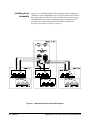
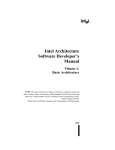
Agilent 75000 SERIES C
E1472A 50 Ohm RF Multiplexer
E1473A 50 Ohm RF Multiplexer Expander
E1474A 75 Ohm RF Multiplexer
E1475A 75 Ohm RF Multiplexer Expander
Service Manual
Copyright© Agilent Technologies, Inc., 1996 - 2006
*E1472-90011*
E1472-90011
Manual Part Number: E1472-90011
Printed: August 2006 Edition 2 Rev 2
Printed in Malaysia E0806
Certification
Agilent Technologies certifies that this product met its published specifications at the time of shipment from the factory. Agilent
Technologies further certifies that its calibration measurements are traceable to the United States National Institute of Standards and
Technology (formerly National Bureau of Standards), to the extent allowed by that organization’s calibration facility, and to the calibration
facilities of other International Standards Organization members.
Warranty
This Agilent Technologies product is warranted against defects in materials and workmanship for a period of one (1) year from date of
shipment. Duration and conditions of warranty for this product may be superseded when the product is integrated into (becomes a part
of) other Agilent products. During the warranty period, Agilent Technologies will, at its option, either repair or replace products which
prove to be defective.
For warranty service or repair, this product must be returned to a service facility designated by Agilent Technologies. Buyer shall prepay
shipping charges to Agilent and Agilent shall pay shipping charges to return the product to Buyer. However, Buyer shall pay all shipping
charges, duties, and taxes for products returned to Agilent from another country.
Agilent warrants that its software and firmware designated by Agilent for use with a product will execute its programming instructions
when properly installed on that product. Agilent does not warrant that the operation of the product, or software, or firmware will be
uninterrupted or error free.
Limitation Of Warranty
The foregoing warranty shall not apply to defects resulting from improper or inadequate maintenance by Buyer, Buyer-supplied products
or interfacing, unauthorized modification or misuse, operation outside of the environmental specifications for the product, or improper site
preparation or maintenance.
The design and implementation of any circuit on this product is the sole responsibility of the Buyer. Agilent does not warrant the Buyer’s
circuitry or malfunctions of Agilent products that result from the Buyer’s circuitry. In addition, Agilent does not warrant any damage that
occurs as a result of the Buyer’s circuit or any defects that result from Buyer-supplied products.
NO OTHER WARRANTY IS EXPRESSED OR IMPLIED. Agilent SPECIFICALLY DISCLAIMS THE IMPLIED WARRANTIES
OF MERCHANTABILITY AND FITNESS FOR A PARTICULAR PURPOSE.
Exclusive Remedies
THE REMEDIES PROVIDED HEREIN ARE BUYER’S SOLE AND EXCLUSIVE REMEDIES. Agilent SHALL NOT BE LIABLE
FOR ANY DIRECT, INDIRECT, SPECIAL, INCIDENTAL, OR CONSEQUENTIAL DAMAGES, WHETHER BASED ON CONTRACT, TORT, OR ANY OTHER LEGAL THEORY.
Notice
The information contained in this document is subject to change without notice. Agilent Technologies MAKES NO WARRANTY OF
ANY KIND WITH REGARD TO THIS MATERIAL, INCLUDING, BUT NOT LIMITED TO, THE IMPLIED WARRANTIES OF
MERCHANTABILITY AND FITNESS FOR A PARTICULAR PURPOSE. Agilent shall not be liable for errors contained herein or for
incidental or consequential damages in connection with the furnishing, performance or use of this material. This document contains
proprietary information which is protected by copyright. All rights are reserved. No part of this document may be photocopied, reproduced,
or translated to another language without the prior written consent of Agilent Technologies, Inc. Agilent assumes no responsibility for the
use or reliability of its software on equipment that is not furnished by Agilent.
U.S. Government Restricted Rights
The Software and Documentation have been developed entirely at private expense. They are delivered and licensed as "commercial
computer software" as defined in DFARS 252.227- 7013 (Oct 1988), DFARS 252.211-7015 (May 1991) or DFARS 252.227-7014 (Jun
1995), as a "commercial item" as defined in FAR 2.101(a), or as "Restricted computer software" as defined in FAR 52.227-19 (Jun 1987)(or
any equivalent agency regulation or contract clause), whichever is applicable. You have only those rights provided for such Software and
Documentation by the applicable FAR or DFARS clause or the Agilent standard software agreement for the product involved.
Agilent E1472A/73A/74A/75A 50W/75W RF Multiplexers/Expanders Module Service Manual
Edition 2 Rev 2
Copyright © 1996-2006 Agilent Technologies, Inc. All Rights Reserved.
Agilent E1472A/73A/74A/75A 50W/75W RF Multiplexers/Expanders Module Service Manual
1
Printing History
The Printing History shown below lists all Editions and Updates of this manual and the printing date(s). The first printing of the manual
is Edition 1. The Edition number increments by 1 whenever the manual is revised. Updates, which are issued between Editions, contain
replacement pages to correct the current Edition of the manual. Updates are numbered sequentially starting with Update 1. When a new
Edition is created, it contains all the Update information for the previous Edition. Each new Edition or Update also includes a revised copy
of this printing history page. Many product updates or revisions do not require manual changes and, conversely, manual corrections may
be done without accompanying product changes. Therefore, do not expect a one-to-one correspondence between product updates and
manual updates.
Edition 1 (Part Number E1472-90010). . . . . . . . . . . . . . . . . . . . . . . August 1992
Edition 2 (Part Number E1472-90011). . . . . . . . . . . . . . . . . . . . . . . . . May 1996
Edition 2 Rev 2 (Part Number E1472-90011) . . . . . . . . . . . . . . . . . August 2006
Safety Symbols
Instruction manual symbol affixed to product.
Indicates that the user must refer to the manual for specific WARNING or CAUTION
information to avoid personal injury or damage to the product.
Alternating current (AC).
Direct current (DC).
Indicates hazardous voltages.
Indicates the field wiring terminal that must
be connected to earth ground before operating
the equipment—protects against electrical
shock in case of fault.
or
Frame or chassis ground terminal—typically
connects to the equipment’s metal frame.
WARNING
CAUTION
Calls attention to a procedure, practice, or condition that could cause bodily injury or death.
Calls attention to a procedure, practice, or condition that could possibly cause damage to
equipment or permanent loss of data.
WARNINGS
The following general safety precautions must be observed during all phases of operation, service, and repair of this product.
Failure to comply with these precautions or with specific warnings elsewhere in this manual violates safety standards of design,
manufacture, and intended use of the product. Agilent Technologies assumes no liability for the customer’s failure to comply with
these requirements.
Ground the equipment: For Safety Class 1 equipment (equipment having a protective earth terminal), an uninterruptible safety earth
ground must be provided from the mains power source to the product input wiring terminals or supplied power cable.
DO NOT operate the product in an explosive atmosphere or in the presence of flammable gases or fumes.
For continued protection against fire, replace the line fuse(s) only with fuse(s) of the same voltage and current rating and type.
DO NOT use repaired fuses or short-circuited fuse holders.
Keep away from live circuits: Operating personnel must not remove equipment covers or shields. Procedures involving the removal of
covers or shields are for use by service-trained personnel only. Under certain conditions, dangerous voltages may exist even with the
equipment switched off. To avoid dangerous electrical shock, DO NOT perform procedures involving cover or shield removal unless you
are qualified to do so.
DO NOT operate damaged equipment: Whenever it is possible that the safety protection features built into this product have been
impaired, either through physical damage, excessive moisture, or any other reason, REMOVE POWER and do not use the product until
safe operation can be verified by service-trained personnel. If necessary, return the product to an Agilent Technologies Sales and Service
Office for service and repair to ensure that safety features are maintained.
DO NOT service or adjust alone: Do not attempt internal service or adjustment unless another person, capable of rendering first aid and
resuscitation, is present.
DO NOT substitute parts or modify equipment: Because of the danger of introducing additional hazards, do not install substitute parts
or perform any unauthorized modification to the product. Return the product to an Agilent Technologies Sales and Service Office for
service and repair to ensure that safety features are maintained.
2
Agilent E1472A/73A/74A/75A 50W/75W RF Multiplexers/Expanders Module Service Manual
DECLARATION OF CONFORMITY
According to ISO/IEC Guide 22 and CEN/CENELEC EN 45014
Manufacturer’s Name:
Manufacturer’s Address:
Agilent Technologies, Incorporated
Measurement Product Generation Unit
th
815 14 ST. S.W.
Loveland, CO 80537 USA
Declares, that the product
Product Name:
Model Number:
Product Options:
50 Ohm RF Multiplexer and Expander
E1472A/E1473A
This declaration covers all options of the above product(s).
Conforms with the following European Directives:
The product herewith complies with the requirements of the Low Voltage Directive 73/23/EEC and the EMC Directive 89/336/EEC
and carries the CE Marking accordingly
Conforms with the following product standards:
EMC
Standard
Limit
IEC 61326-1:1997+A1:1998 / EN 61326-1:1997+A1:1998
CISPR 11:1997 +A1:1997 / EN 55011:1998
IEC 61000-4-2:1995+A1:1998 / EN 61000-4-2:1995
IEC 61000-4-3:1995 / EN 61000-4-3:1995
IEC 61000-4-4:1995 / EN 61000-4-4:1995
IEC 61000-4-5:1995 / EN 61000-4-5:1995
IEC 61000-4-6:1996 / EN 61000-4-6:1996
IEC 61000-4-11:1994 / EN 61000-4-11:1994
Group 1 Class A [1]
4kV CD, 8kV AD
3 V/m, 80-1000 MHz
0.5kV signal lines, 1kV power lines
0.5 kV line-line, 1 kV line-ground
3V, 0.15-80 MHz
I cycle, 100%
Canada: ICES-001:1998
Australia/New Zealand: AS/NZS 2064.1
Safety
IEC 61010-1:1990+A1:1992+A2:1995 / EN 61010-1:1993+A2:1995
Canada: CSA C22.2 No. 1010.1:1992
UL 3111-1:1994
Supplemental Information:
[1]
The product was tested in a typical configuration with Agilent Technologies test systems.
September 5, 2000
Date
Name
Quality Manager
Title
For further information, please contact your local Agilent Technologies sales office, agent or distributor.
Authorized EU-representative: Agilent Technologies Deutschland GmbH, Herrenberger Straβe 130, D 71034 Böblingen, Germany
Agilent E1472A/73A/74A/75A 50W/75W RF Multiplexers/Expanders Module Service Manual
3
DECLARATION OF CONFORMITY
According to ISO/IEC Guide 22 and CEN/CENELEC EN 45014
Manufacturer’s Name:
Manufacturer’s Address:
Agilent Technologies, Incorporated
Measurement Product Generation Unit
th
815 14 ST. S.W.
Loveland, CO 80537 USA
Declares, that the product
Product Name:
Model Number:
Product Options:
75 Ohm RF Multiplexer and Expander
E1474A/E1475A
This declaration covers all options of the above product(s).
Conforms with the following European Directives:
The product herewith complies with the requirements of the Low Voltage Directive 73/23/EEC and the EMC Directive 89/336/EEC
and carries the CE Marking accordingly
Conforms with the following product standards:
EMC
Standard
Limit
IEC 61326-1:1997+A1:1998 / EN 61326-1:1997+A1:1998
CISPR 11:1997 +A1:1997 / EN 55011:1998
IEC 61000-4-2:1995+A1:1998 / EN 61000-4-2:1995
IEC 61000-4-3:1995 / EN 61000-4-3:1995
IEC 61000-4-4:1995 / EN 61000-4-4:1995
IEC 61000-4-5:1995 / EN 61000-4-5:1995
IEC 61000-4-6:1996 / EN 61000-4-6:1996
IEC 61000-4-11:1994 / EN 61000-4-11:1994
Group 1 Class A [1]
4kV CD, 8kV AD
3 V/m, 80-1000 MHz
0.5kV signal lines, 1kV power lines
0.5 kV line-line, 1 kV line-ground
3V, 0.15-80 MHz
I cycle, 100%
Canada: ICES-001:1998
Australia/New Zealand: AS/NZS 2064.1
Safety
IEC 61010-1:1990+A1:1992+A2:1995 / EN 61010-1:1993+A2:1995
Canada: CSA C22.2 No. 1010.1:1992
UL 3111-1:1994
Supplemental Information:
[1]
The product was tested in a typical configuration with Agilent Technologies test systems.
September 5, 2000
Date
Name
Quality Manager
Title
For further information, please contact your local Agilent Technologies sales office, agent or distributor.
Authorized EU-representative: Agilent Technologies Deutschland GmbH, Herrenberger Straβe 130, D 71034 Böblingen, Germany
4
Agilent E1472A/73A/74A/75A 50W/75W RF Multiplexers/Expanders Module Service Manual
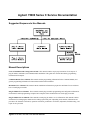
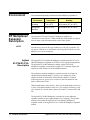
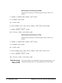
Agilent 75000 Series C Service Documentation
Suggested Sequence to Use Manuals
Manual Descriptions
Series C Installation and Getting Started Guide. This manual contains step-by-step instructions for all aspects of
plug-in module, mainframe, and command module installation. This guide also contains introductory programming
information and examples.
Command Module User’s Manual. This manual contains programming information for the Command Module, and
general programming information for instruments installed in the mainframe.
Mainframe User’s Manual. This manual contains installation information to prepare the mainframe for use and shows
how to install plug-in modules.
Plug-In Module User’s Manuals. These manuals contain plug-in module programming and configuration information.
Each manual contains programming examples and a complete SCPI command reference for the plug-in module.
Plug-In Module Service Manuals. These manuals contain plug-in module service information. Each manual contains
information for exchanging the module and/or ordering replaceable parts. Depending on the module, information and
procedures for functional verification, operation verification, performance verification, adjustment, troubleshooting, and
repair are also provided.
Agilent E1472A/73A/74A/75A Service Manual
5
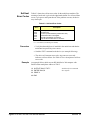
What’s in this Manual
Manual Overview
This manual shows how to service the Agilent E1472A/E1474A RF Multiplexers and the Agilent
E1473A/E1475A RF Multiplexer Expanders. Consult the Agilent E1472A/73A User’s Manual or the Agilent
E1474A/75A User’s Manual for additional information on installing, configuring, and operating the modules.
Consult the appropriate mainframe or command module user’s manual for information on configuring and
operating the mainframe.
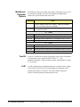
Manual Content
Chap
6
Title
Content
1
General
Information
Provides a basic description and lists the test equipment required for
service.
2
Verification
Tests
Functional verification, operation verification, and performance
verification tests.
3
Replaceable
Parts
Replaceable parts lists and illustrations.
4
Service
Procedures to aid in fault isolation and repair.
Agilent E1472A/73A/74A/75A Service Manual
Notes
Agilent E1472A/73A/74A/75A Service Manual
7
Notes
8
Agilent E1472A/73A/74A/75A Service Manual
Table of Contents
Chapter 1 — General Information
Introduction . . . . . . . . . . . . . . . . . . . . . . . . . . . . . . . . . . . . . . . 11
Relay Life . . . . . . . . . . . . . . . . . . . . . . . . . . . . . . . . . . . . . . . . 12
End-of-Life Detection . . . . . . . . . . . . . . . . . . . . . . . . . . . . . . . 13
Replacement Strategy . . . . . . . . . . . . . . . . . . . . . . . . . . . . . . . . 13
Safety Considerations . . . . . . . . . . . . . . . . . . . . . . . . . . . . . . . . . . 14
Warnings and Cautions . . . . . . . . . . . . . . . . . . . . . . . . . . . . . . . 14
Inspection/Shipping . . . . . . . . . . . . . . . . . . . . . . . . . . . . . . . . . . . 16
Initial Inspection . . . . . . . . . . . . . . . . . . . . . . . . . . . . . . . . . . 16
Shipping Guidelines . . . . . . . . . . . . . . . . . . . . . . . . . . . . . . . . 17
Environment . . . . . . . . . . . . . . . . . . . . . . . . . . . . . . . . . . . . . . 18
RF Multiplexer/Expander Description . .
Agilent E1472A/E1473A Description
Agilent E1474A/E1475A Description
Multiplexer/Expander Specifications .
Multiplexer/Expander Serial Numbers
Multiplexer/Expander Options . . . .
Test Kit . . . . . . . . . . . . . . . .
CLIP . . . . . . . . . . . . . . . . . .
.
.
.
.
.
.
.
.
.
.
.
.
.
.
.
.
.
.
.
.
.
.
.
.
.
.
.
.
.
.
.
.
.
.
.
.
.
.
.
.
.
.
.
.
.
.
.
.
.
.
.
.
.
.
.
.
.
.
.
.
.
.
.
.
.
.
.
.
.
.
.
.
.
.
.
.
.
.
.
.
.
.
.
.
.
.
.
.
.
.
.
.
.
.
.
.
.
.
.
.
.
.
.
.
.
.
.
.
.
.
.
.
.
.
.
.
.
.
.
.
.
.
.
.
.
.
.
.
.
.
.
.
.
.
.
.
.
.
.
.
.
.
.
.
.
.
.
.
.
.
.
.
.
.
.
.
.
.
.
.
.
.
.
.
.
.
.
.
.
.
.
.
.
.
.
.
.
.
.
.
.
.
.
.
18
18
19
19
19
20
20
20
Recommended Test Equipment . . . . . . . . . . . . . . . . . . . . . . . . . . . . 21
Chapter 2 — Verification Tests
Introduction . . . . . . . . . . .
Test Conditions/Procedures .
Performance Test Record . .
Verification Test Examples .
.
.
.
.
.
.
.
.
.
.
.
.
.
.
.
.
.
.
.
.
.
.
.
.
.
.
.
.
.
.
.
.
.
.
.
.
.
.
.
.
.
.
.
.
.
.
.
.
.
.
.
.
.
.
.
.
.
.
.
.
.
.
.
.
.
.
.
.
.
.
.
.
.
.
.
.
.
.
.
.
.
.
.
.
.
.
.
.
.
.
.
.
.
.
.
.
.
.
.
.
.
.
.
.
.
.
.
.
.
.
.
.
23
23
23
23
Multiplexer Functional Verification . . . . . . . . . . . . . . . . . . . . . . . . . . 24
Procedure . . . . . . . . . . . . . . . . . . . . . . . . . . . . . . . . . . . . . . 24
Example . . . . . . . . . . . . . . . . . . . . . . . . . . . . . . . . . . . . . . . 24
Expander Functional Verification . . . . . . . . . . . . . . . . . . . . . . . . . . . 24
Procedure . . . . . . . . . . . . . . . . . . . . . . . . . . . . . . . . . . . . . . 24
Example . . . . . . . . . . . . . . . . . . . . . . . . . . . . . . . . . . . . . . . 25
Operation Verification . . . . . . . . . . . . . . . . . . . . . . . . . . . . . . . . . 25
Performance Verification . . . . . . . . . . . . . . . . . . . . . . . . . . . . . . . . 25
Making Test Connections . . . . . . . . . . . . . . . . . . . . . . . . . . . . . . 25
Test 2-1: VSWR Test . . . . . . . . . . . . . . . . . . . . . . . . . . . . . . . . 27
Agilent E1472A/73A/74A/75A Service Manual
9
Performance Test Record . . .
Test Limits . . . . . . . .
Measurement Uncertainty .
Test Accuracy Ratio (TAR)
.
.
.
.
.
.
.
.
.
.
.
.
.
.
.
.
.
.
.
.
.
.
.
.
.
.
.
.
.
.
.
.
.
.
.
.
.
.
.
.
.
.
.
.
.
.
.
.
.
.
.
.
.
.
.
.
.
.
.
.
.
.
.
.
.
.
.
.
.
.
.
.
.
.
.
.
.
.
.
.
.
.
.
.
.
.
.
.
.
.
.
.
.
.
.
.
.
.
.
.
.
.
.
.
.
.
.
.
.
.
.
.
.
.
.
.
33
33
34
36
.
.
.
.
.
.
.
.
.
.
.
.
.
.
.
.
.
.
.
.
.
.
.
.
.
.
.
.
.
.
.
.
.
.
.
.
.
.
.
.
.
.
.
.
.
.
.
.
.
.
.
.
.
.
.
.
.
.
.
.
.
.
.
.
.
.
.
.
.
.
.
.
.
.
.
.
.
.
.
.
.
.
.
.
.
.
.
.
.
.
.
.
.
.
.
.
.
.
.
.
.
.
.
.
.
.
.
.
41
41
41
41
Chapter 3 — Replaceable Parts
Introduction . . . . . . .
Replaceable Parts List
Exchange Assemblies
Ordering Information
.
.
.
.
.
.
.
.
.
.
.
.
.
.
.
.
.
.
.
.
Chapter 4 — Service
Introduction . . . . . . . . . . . . . . . . . . . . . . . . . . . . . . . . . . . . . . . 49
Repair Strategy . . . . . . . . . . . . . . . . . . . . . . . . . . . . . . . . . . . . . 49
Equipment Required . . . . . . . . . . . . . . . . . . . . . . . . . . . . . . . . . 49
Service Aids . . . . . . . . . . . . . . . . . . . . . . . . . . . . . . . . . . . . . 50
Troubleshooting . . . . . . .
Identifying the Problem .
Testing the Assembly . .
Isolating to an Assembly .
Self-test Error Codes . . .
Disassembly . . . . . . .
.
.
.
.
.
.
.
.
.
.
.
.
.
.
.
.
.
.
.
.
.
.
.
.
.
.
.
.
.
.
.
.
.
.
.
.
.
.
.
.
.
.
.
.
.
.
.
.
.
.
.
.
.
.
.
.
.
.
.
.
.
.
.
.
.
.
.
.
.
.
.
.
.
.
.
.
.
.
.
.
.
.
.
.
.
.
.
.
.
.
.
.
.
.
.
.
.
.
.
.
.
.
.
.
.
.
.
.
.
.
.
.
.
.
.
.
.
.
.
.
.
.
.
.
.
.
.
.
.
.
.
.
.
.
.
.
.
.
.
.
.
.
.
.
.
.
.
.
.
.
.
.
.
.
.
.
.
.
.
.
.
.
.
.
.
.
.
.
.
.
.
.
.
.
.
.
.
.
.
.
50
50
51
52
53
54
Repair/Maintenance Guidelines . . .
ESD Precautions . . . . . . . .
Soldering Printed Circuit Boards
Post-Repair Safety Checks . . . .
.
.
.
.
.
.
.
.
.
.
.
.
.
.
.
.
.
.
.
.
.
.
.
.
.
.
.
.
.
.
.
.
.
.
.
.
.
.
.
.
.
.
.
.
.
.
.
.
.
.
.
.
.
.
.
.
.
.
.
.
.
.
.
.
.
.
.
.
.
.
.
.
.
.
.
.
.
.
.
.
.
.
.
.
.
.
.
.
.
.
.
.
.
.
.
.
.
.
.
.
.
.
.
.
57
57
57
57
Appendix A — Verification Tests - C Programs
Functional Verification Tests . . . . . . . . . . . . . . . . . . . . . . . . . . . . . . 59
Example: Multiplexer Self Test . . . . . . . . . . . . . . . . . . . . . . . . . . . 59
Example: Expander Self Test . . . . . . . . . . . . . . . . . . . . . . . . . . . . 60
Performance Verification Test . . . . . . . . . . . . . . . . . . . . . . . . . . . . . . 61
Example: VSWR Test . . . . . . . . . . . . . . . . . . . . . . . . . . . . . . . . 61
10
Agilent E1472A/73A/74A/75A Service Manual
Chapter 1
General Information
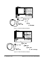
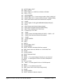
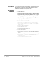
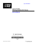
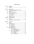
Introduction
This manual contains information required to test, troubleshoot, and repair
the Agilent E1472A 50 Ohm RF Multiplexer, the Agilent 1473A 50 Ohm
RF Multiplexer Expander, the Agilent E1474A 75 Ohm RF Multiplexer,
and the Agilent E1475A 75 Ohm RF Multiplexer Expander (see Figures 1-1
and 1-2).
Figure 1-1. Agilent E1472A/E1474A RF Multiplexers
Agilent E1472A/73A/74A/75A Service Manual
General Information 11
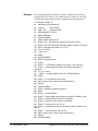
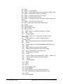
Figure 1-2. Agilent E1473A/E1475A RF Multiplexer Expanders
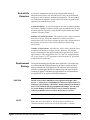
Relay Life
Electromechanical relays are subject to normal wear-out. Relay life depends
on several factors. The effects of loading and switching frequency are
briefly discussed below:
Relay Load. In general, higher power switching reduces relay life. In
addition, capacitive/inductive loads and high inrush currents (e.g., when
turning on a lamp or motor) reduce relay life. Exceeding the specified
maximum inputs can cause catastrophic failure.
Switching Frequency. Relay contacts heat up when switched. As the
switching frequency increases, the contacts have less time to dissipate heat.
The resulting increase in contact temperature reduces relay life.
12 General Information
Agilent E1472A/73A/74A/75A Service Manual
End-of-Life
Detection
A preventive maintenance routine can prevent problems caused by
unexpected relay failure. The end of the life of a relay can be determined
using one or more of the three methods described below. The best method
(or combination of methods), as well as the failure criteria, depends on the
application in which the relay is used.
Contact Resistance. As the relay begins to wear out, its contact resistance
will increase. When the resistance exceeds a pre-determined value, the relay
should be replaced. Typically, a relay should be replaced when the contact
resistance exceeds 1.0 Ohm.
Stability of Contact Resistance. The stability of the contact resistance
decreases with age. Using this method, the contact resistance is
measured several (5-10) times, and the variance of the measurements is
determined. An increase in the variance indicates deteriorating
performance.
Number of Operations. Alternatively, relays can be replaced after a
predetermined number of contact closures. However, this method
requires knowledge of the applied load and life specifications for the
applied load. For the Agilent E1472A/73A/74A/75A, maximum relay
life is specified at 5 X 10⁶ operations with no load and 105 operations
at the maximum rated load.
Replacement
Strategy
CAUTION
NOTE
The replacement strategy also depends on the application. If all of the relays
see similar loads and switching frequencies, the entire circuit board can be
replaced when the end of life approaches. The sensitivity of the application
should be weighed against the cost of replacing relays with some useful life
remaining. In general, individual relay replacement is not recommended for
the Agilent E1472A or Agilent E1474A RF Multiplexers.
The RF relays in these multiplexers are high-mass, high-pin-count
devices. A solder pot is recommended for removal or replacement. If a
solder pot is not available, a RF surface mount soldering iron should be
used. Use of standard soldering equipment will damage the relay and
PC board. Damage to the PC board or relays caused by improper
soldering techniques is not covered by the product’s warranty.
Relays that wear out normally or fail due to misuse should not be
considered defective and are not covered by the product’s warranty.
Agilent E1472A/73A/74A/75A Service Manual
General Information 13
Safety
Considerations
This product is a Safety Class I instrument that is provided with a protective
earth terminal when installed in the mainframe. The instrument, mainframe,
and all related documentation should be reviewed for familiarization with
safety markings and instructions before operation or service.
Refer to the WARNINGS page (page 2) in this manual for a summary of
safety information. Safety information for testing and service follows and is
also found throughout this manual.
Warnings and
Cautions
WARNING
This section contains WARNINGS which must be followed for your
protection and CAUTIONS which must be followed to avoid damage to the
equipment when performing instrument maintenance or repair.
SERVICE-TRAINED PERSONNEL ONLY. The information in this
manual is for service-trained personnel who are familiar
with electronic circuitry and are aware of the hazards involved.
To avoid personal injury or damage to the instrument, do not
perform procedures in this manual or do any servicing unless
you are qualified to do so.
CHECK MAINFRAME POWER SETTINGS. Before applying
power, verify that the mainframe setting matches the line
voltage and that the correct fuse is installed. An uninterruptible
safety earth ground must be provided from the main power
source to the supplied power cord set.
GROUNDING REQUIREMENTS. Interruption of the protective
(grounding) conductor (inside or outside the mainframe) or
disconnecting the protective earth terminal will cause a
potential shock hazard that could result in personal injury.
(Grounding one conductor of a two-conductor outlet is not
sufficient protection.)
IMPAIRED PROTECTION. Whenever it is likely that instrument
protection has been impaired, the mainframe must be made
inoperative and be secured against any unintended operation.
REMOVE POWER IF POSSIBLE. Some procedures in this
manual may be performed with power supplied to the
mainframe while protective covers are removed. Energy
available at many points may, if contacted, result in personal
injury. (If maintenance can be performed without power applied,
the power should be removed.)
14 General Information
Agilent E1472A/73A/74A/75A Service Manual
WARNING
USING AUTOTRANSFORMERS. If the mainframe is to be
energized via an autotransformer (for voltage reduction) make
sure the common terminal is connected to neutral (that is, the
grounded side of the main’s supply).
CAPACITOR VOLTAGES. Capacitors inside the mainframe may
remain charged even when the mainframe has been
disconnected from its source of supply.
USE PROPER FUSES. For continued protection against fire
hazard, replace the line fuses only with fuses of the same
current rating and type (such as normal blow, time delay, etc.).
Do not use repaired fuses or short-circuited fuseholders.
SHOCK HAZARD. Only service-trained personnel who are
aware of the hazards involved should install, remove, or
configure the multiplexer or expander. Before you remove any
installed module, disconnect AC power from the mainframe and
from other modules that may be connected to the multiplexer or
expander.
CHANNEL WIRING INSULATION. All channels that have a
common connection must be insulated so that the user is
protected from electrical shock. This means wiring for all
channels must be insulated as though each channel carries the
voltage of the highest voltage channel.
CAUTION
MAXIMUM INPUTS. The maximum voltage that can be applied to
any terminal is 42 V Peak (any center or chassis to any other center of
chassis). The maximum current per channel or common is 1 A DC or
AC RMS. The maximum power that can be applied to any channel or
common is 24 W or 24 VA.
STATIC ELECTRICITY. Static electricity is a major cause of
component failure. To prevent damage to the electrical components in
the multiplexer or expander, observe anti-static techniques whenever
working on the device.
RELAY REMOVAL. The RF relays used in these multiplexers are
high-mass, high-pin-count devices. Individual relay removal is not
recommended. A solder pot is required for removal or replacement. Use of
standard soldering equipment will cause damage to the relay and PC board.
Agilent E1472A/73A/74A/75A Service Manual
General Information 15
Inspection/
Shipping
This section contains initial (incoming) inspection and shipping guidelines
for the multiplexer/expander modules.
Initial
Inspection
WARNING
Use the steps in Figure 1-3 as guidelines to perform initial inspection of one
of the modules. Verification Tests are optional.
To avoid possible hazardous electrical shock, do not perform
electrical tests if there are signs of shipping damage to the
shipping container or to the instrument.
Notify Agilent and carrier.
Notify Agilent
Return to Agilent
Figure 1-3. Initial (Incoming) Inspection Guidelines
16 General Information
Agilent E1472A/73A/74A/75A Service Manual
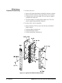
Shipping
Guidelines
Follow the steps in Figure 1-4 to return one of the multiplexer/expander
modules to a Agilent Technologies Sales and Support Office or Service
Center.
1 Prepare the Multiplexer
• Remove user wiring from terminal block
• Attach tag to module/pod that identifies
- Owner
- Model Number/Serial Number
- Service Required
• Place tagged device in approved anti-static bag
2 Package the Multiplexer
• Place packaged multiplexer in shipping carton*
• Place 75 to 100 mm (3 to 4 inches) of shockabsorbing material around the multiplexer.
• Seal the shipping carton securely.
• Mark the shipping carton FRAGILE.
3 Ship the Multiplexer to Agilent Technologies
• Place address label on shipping carton
• Send carton to Agilent Technologies
Figure 1-4. Packaging/Shipping Guidelines
* We recommend that you use the same shipping materials as those used in factory packaging (available from Agilent Technologies).
For other (commercially-available) shipping materials, use a double wall-carton with minimum 2.4 MPa (350 psi) test.
Agilent E1472A/73A/74A/75A Service Manual
General Information 17
Environment
The recommended operating environment for the multiplexers/ expanders is:
Environment
Temperature
Humidity
Operating
0oC to +55oC
<95% relative (0oC to +40oC)
Storage and
Shipment
-40oC to +75oC
<95% relative (0oC to +40oC)
RF Multiplexer/
Expander
Description
The Agilent E1472A and E1474A RF Multiplexer modules are
"instruments" in the slots of a VXIbus mainframe. Each module is assigned
an error queue, input and output buffers, and a status register.
NOTE
Instruments are based on the logical addresses of the plug-in modules. See
the Agilent 75000 Series C Installation and Getting Started Guide to set the
addresses to create an instrument.
Agilent
E1472A/E1473A
Description
The Agilent E1472A 50 Ohm RF Multiplexer and the Agilent E1473A 50
Ohm RF Multiplexer Expander are VXI bus C-Size register-based products.
The Agilent E1472A RF Multiplexer and the Agilent E1473A RF
Multiplexer Expander each provide six banks of 4:1 switching. Inputs and
outputs for either module use 50 Ohm SMB connectors.
The multiplexer and each multiplexer expander consists of six banks of
channels (bank 0 through bank 5) to form six 4:1 multiplexers. Each
channel in a bank is connected to COM when the channel is CLOSed.
Following power-on, power off, or a card reset, the first channel in each
bank is connected to COM.
Channel numbering is in the form bc, where b is the bank number (from 0 to
5) and c is the channel number (from 0 to 3). For example, following a card
reset, channel 20 is closed (that is, channel 0 in bank 2 is connected to COM
20).
The Agilent E1472A RF Multiplexer can control up to two additional
expander modules for up to eighteen banks of 4:1 switching. The expander
modules can be either the Agilent E1473A 50 Ohm RF Multiplexer
Expander module or the Agilent E1475A 75 Ohm RF Multiplexer Expander
module.
18 General Information
Agilent E1472A/73A/74A/75A Service Manual
The Agilent E1473A RF Multiplexer Expander Module can be inserted in a
C-Size VXI bus mainframe next to the multiplexer, or can be located up to
eight meters away from the multiplexer using remote expander cables.
Locating the expander module close to the external device keeps connecting
cable lengths to a minimum, thereby reducing the possibility of cross-talk
and insertion loss of high frequency signals.
Agilent
E1474A/E1475A
Description
The Agilent E1474A 75 Ohm RF Multiplexer and the Agilent E1475A 75
Ohm RF Multiplexer Expander are identical in operation to the Agilent
E1472A/E1473A described earlier in this chapter with the exception of the
characteristic impedance of the RF channels.
Inputs and outputs for either module use special 75 Ohm SMB connectors.
The special connectors and their mating connectors are listed in the Agilent
E1474A/E1475A RF Multiplexer/Expander User’s Manual.
Multiplexer/
Expander
Specifications
Specifications are listed in Appendix A of the Agilent E1472A/E1473A RF
Multiplexer/RF Multiplexer Expander User’s Manual and the Agilent
E1474A/E1475A RF Multiplexer/RF Multiplexer Expander User’s Manual.
These specifications are the performance standards or limits against which
the modules may be tested.
Multiplexer/
Expander
Serial Numbers
Devices covered by this manual are identified by a serial number prefix
listed on the title page. Agilent Technologies uses a two-part serial number
in the form XXXXAYYYYY, where XXXX is the serial prefix, A is the
country of origin (A=USA), and YYYYY is the serial suffix. The serial
number prefix identifies a series of identical instruments. The serial number
suffix is assigned sequentially to each instrument. The serial number plate
is located on the right-hand shield near the backplane connectors.
Agilent E1472A/73A/74A/75A Service Manual
General Information 19
Multiplexer/
Expander
Options
The following cables are available from Agilent Technologies for use with
the multiplexer/expander. For other cable lengths and configurations,
contact your Agilent Technologies sales office.
Agilent PN
Cable
E1473-80002 Remote Expander Cable Kit to remote mount either the Agilent
E1473A or Agilent E1475A next to the DUT. Cables are 0.8 Meters
long and can be daisy chained up to 8 Meters
E1472-61601 RMD Cable (3-to-1 Cable). Two cables are required to operate one or
more expander modules.
50 Ω Cables
8120-5629
Right-angle to right-angle female SMB connector (125 mm)
8120-5091
Straight to straight female SMB connector (125 mm)
8120-5609
Right-angle female to bulkhead mount male SMB connector (175 mm)
8120-5614
Right-angle female SMB to BNC female connector (175 mm)
75 Ω Cables
8120-5591
Right-angle to right-angle female SMB connector (125 mm)
8120-5584
Straight to straight female SMB connector (125 mm)
8120-5580
Right-angle female to bulkhead mount male SMB connector (175 mm)
8120-5619
Right-angle female SMB to BNC connector (175 mm)
Test Kit
A test kit is available from Agilent Technologies for use in the Performance
Verification tests of the Agilent E1474A/E1475A 75 Ω RF
Multiplexer/Expander. Order Agilent part number E1474-80000. See Table
1-1 for kit parts.
CLIP
A CLIP (Component Level Information Packet) is available for the Agilent
E1472A/E1473A/E1474A/E1475A RF Multiplexers/Expanders (order
Agilent part number E1472-90033). This CLIP contains component
locators, schematic diagrams, and detailed parts lists.
20 General Information
Agilent E1472A/73A/74A/75A Service Manual
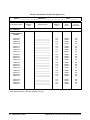
Recommended
Test Equipment
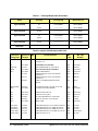
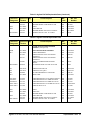
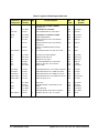
Table 1-1 lists the test equipment recommended for testing and servicing the
module. Essential requirements for each piece of test equipment are
described in the Requirements column. Other equipment may be substituted
as long as it meets the requirements shown in the Requirements column.
Table 1-1. Recommended Test Equipment
Instrument
Requirements
Recommended
Model
Use*
Controller, GPIB
GPIB compatibility as defined by IEEE Standard
488-1988 and the identical ANSI Standard
MC1.1: SH1, AH1, T2, TE0, L2, LE0, SR0,
RL0, PP0, DC0, DT0, and C1, 2, 3,
4, 5.
HP 9000 Series 300
or
IBM Compatible PC with
BASIC
F,O,
P,T
Mainframe
Compatible with multiplexer/expander
E1401B/T or E1421B
(requires E1405A/B or
E1406A)
F,O,
P,T
Command Module
Compatible with multiplexer/expander
E1405A/B or
E1406A
F,O,
P,T
Network Analyzer
VSWR from 10 MHZ to 3 GHz.
Agilent 8753C
O, P,T
S-Parameter Test Set
Compatible with Agilent 8753C , single port
50 Ω for Agilent E1472A/E1473A
75 Ω for Agilent E1474A/E1475A
Agilent 85046A for Agilent
E1472A/E1473A
or
Agilent 85046B for Agilent
E1474A/1475A
O, P,T
Adapters and Cables
Digital Multimeter
E1472A/E1473A 50 Ω
APC-7-to-SMA (female)
SMA-to-SMA cable (male-male)
SMA -to- SMB (female-female)
SMB LOAD(female)
SMB SHORT (male)
SMB Feedthrough (male-male)
50 Ω impedance
Agilent PN 11534A
—————
—————
Agilent PN 1250-0676
—————
—————
E1474A/E1475A 75 Ω
Test Kit (contains the following parts)**
N-to-SMB cable (male-female)
SMB OPEN (male)
SMB LOAD (female)
SMB SHORT (male)
SMB Feedthrough (male-male)
75 Ω impedance
Agilent PN E1474-80000**
Agilent PN 8120-4482
Agilent PN 1250-2354
Agilent PN 1250-2343
Agilent PN 1250-2358
Agilent PN 1250-2337
4-wire ohms
2-wire ohms (up to 1 GΩ )
Agilent 3458A or
Agilent 34401A
O, P,T
T
* F = Functional Verification Tests, O = Operation Verification Tests, P = Performance Verification Tests, T = Troubleshooting
** Test Kit must be ordered as a separate part from Agilent Technologies
Agilent E1472A/73A/74A/75A Service Manual
General Information 21
22 General Information
Agilent E1472A/73A/74A/75A Service Manual
Chapter 2
Verification Tests
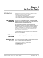
Introduction
The three levels of test procedures described in this chapter are used to
verify that the multiplexer or multiplexer expander:
• is fully functional (Functional Verification)
• meets selected testable specifications (Operation Verification)
• meets all testable specifications (Performance Verification)
Test Conditions/
Procedures
See Table 1-1 for test equipment requirements. You should complete the
Performance Verification tests at least once a year. For heavy use or severe
operating environments, perform the tests more often.
The verification tests assume that the person performing the tests
understands how to operate the mainframe, the multiplexer/expander, and
specified test equipment. The test procedures do not specify equipment
settings for test equipment, except in general terms. It is assumed that a
qualified, service-trained technician will select and connect the cables,
adapters, and probes required for the test.
It is assumed that the temperature is no greater than 25oC and the relative
humidity is no greater than 40%.
Performance
Test Record
Verification Test
Examples
The results of each Performance Verification test may be recorded in the
Performance Test Record (Table 2-3).
Each verification test procedure includes an example program that performs
the test. All example programs assume the following:
•
•
•
•
Controller is an HP 9000 Series 200/300 computer
Programming language is BASIC
Switch address is 70915
Switch card number is 1
Agilent E1472A/73A/74A/75A Service Manual
Verification Tests 23
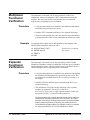
Multiplexer
Functional
Verification
Procedure
The Functional Verification Test for the Agilent E1472A/E1474A
multiplexers consists of sending the *TST? command and checking the
response. This test can be used to verify that the device is connected
properly and is responding to basic commands.
1. Verify that the multiplexer is installed in the mainframe and that the
mainframe has passed its power-on test.
2. Send the *TST? command to the device (see example following).
3. The device will return an error code. Any non-zero error code indicates
a self-test failure. See Table 4-3 for a description of self-test error codes.
Example
An example follows which uses an HP 9000 Series 300 computer with
BASIC and an multiplexer address of 70915.
10 OUTPUT 70915;"*TST?"
Send the self-test command
20 ENTER 70915;A
Get response
30 PRINT A
40 END
Expander
Functional
Verification
Procedure
The Functional Verification Test for the Agilent E1473A/E1475A RF
Multiplexer Expanders consists of sending the :COPTion? query command
and checking the response. This test can be used to verify that the device is
connected properly and is responding to basic commands.
1. Verify that the multiplexer is installed in the mainframe and that both
the mainframe and multiplexer have passed the power-on test. This
test assumes the conditions listed in Test Conditions/Procedures in
this chapter.
2. Send the SYSTem:COPTion? query command to the device (see
example following).
3. The multiplexer will return a string indicating if any expander
modules are connected. The string is in the form:
E1474A,E1475A,0 if only a single expander module (in this case
an Agilent E1475A) is connected to the multiplexer.
The first parameter of the returned string indicates the type of multiplexer
installed in the mainframe (Agilent E1472A or E1474A). The second
parameter in the string is the model number of the first installed expander
module, and the last parameter in the string is the model number of a
second installed expander module. If no expander modules are installed,
the string returned will be E1474A,0,0 and indicates a failure.
24 Verification Tests
Agilent E1472A/73A/74A/75A Service Manual
Example
An example follows which uses an HP 9000 Series 300 computer with
BASIC and an multiplexer address of 70915. The multiplexer is assumed to
be switch card 1.
10 DIM A$[50]
20 OUTPUT 70915;"SYST:COPT? 1"
Send identify options command
30 ENTER 70915;A$
Get response
40 PRINT A$
50 END
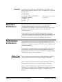
Operation
Verification
The procedures in this section are used to provide a high degree of
confidence that the multiplexer/expander is meeting published
specifications. The Operation Verification tests are usually a subset of the
Performance Verification tests and are suitable for checkout after
performing repairs.
For the Agilent E1472A/E1474A RF Multiplexer modules, Operation
Verification is performed by completing the VSWR Test as described in the
performance verification test procedures (Test 2-1). This test is usually
sufficient to verify that the instrument is meeting its specifications.
Performance
Verification
The procedures in this section are used to test the multiplexer’s electrical
performance using the specifications in Appendix A of the Agilent E1472A
/E1473A User’s Manual or Agilent E1474A /E1475A User’s Manual as the
performance standards.
The performance verification test is a test of the VSWR for each channel of
the multiplexer. This test is sufficient to determine that the multiplexer is
operating within specifications. This test is suitable for incoming inspection,
troubleshooting, and preventive maintenance.
Making Test
Connections
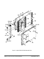
Figure 2-1 shows typical test connections, cables, and adapters required to
test the Agilent E1472A/E1473A 50 Ohm RF Multiplexer/Expander.
Figure 2-2 shows typical test connections, cables, and adapters required to
test the Agilent E1474A/E1475A 75 Ohm RF Multiplexer/Expander.
Figure 2-3 shows the RMD cable connections needed to test either the
Agilent E1473A or Agilent E1475A RF Multiplexer Expander. Refer to the
list of multiplexer/expander options in Chapter 1 for RMD cable part
numbers.
Agilent E1472A/73A/74A/75A Service Manual
Verification Tests 25
Figure 2-1. 50 Ohm Test Cables and Adapters
Figure 2-2. 75 Ohm Test Cables and Adapters
26 Verification Tests
Agilent E1472A/73A/74A/75A Service Manual
Figure 2-3. RF Multiplexer Expander Connections
Test 2-1: VSWR
Test
100 MHz to 500 MHz
Measurements
This test checks to see if all channels meet the VSWR specification for the
multiplexer.
1. Setup and Calibrate the Network Analyzer
•
•
•
•
Turn on the test set and allow at least a one-hour warm up period.
Press the PRESET button.
Select the SWR measurement type from the FORMAT menu.
Set the START frequency to 100 MHz and the STOP frequency to
500 MHz.
• Select the CAL menu. Select the 3.5 mm cal kit.
Agilent E1472A/73A/74A/75A Service Manual
Verification Tests 27
• From the CAL menu, select a single port measurement (typically
port S11).
• Calibrate the port for OPEN, SHORT, and LOAD using the
appropriate test connectors on the cable that will be used for the
test (refer to Table 1-1). Press DONE when the Network Analyzer
indicates it is calibrated and ready for a measurement.
• Set an appropriate scale per division to measure the VSWR
(typically 100 mV/DIV).
NOTE
The connectors, cables, adapters, loads, and shorts used to calibrate the
Network Analyzer must be the same connectors, cables, adapters, and loads
used in the VSWR tests.
2. Measure Bank 0 VSWR
• Turn mainframe power ON
• Send *RST to multiplexer
• Connect the Port 1 test cable to the COM 00 port on the
multiplexer/expander as shown in Figure 2-4.
• Install the appropriate load on Channel 00 as shown in Figure 2-4.
• Send CLOS (@ccmm00) to close chan 00, where cc = card
number and mm = module number.
• Observe the Network Analyzer response. Select marker search for
MAX (or, manually locate the maximum value indicated) and
record the measurement VSWR in Table 2-3 for Channel 00.
• Send OPEN (@ccmm00) to open chan 00, where cc = card
number and mm = module number.
28 Verification Tests
Agilent E1472A/73A/74A/75A Service Manual
Figure 2-4. Channel 00 VSWR Test Connections
3. Repeat for Channels 01, 02, and 03
• Repeat step 2 for channels 01, 02 and 03.
• Move the load to the channel under test.
• Use CLOS (@ccmmnn) and OPEN (@ccmmnn), where cc = card
number, mm = module number, and nn = channel number.
4. Repeat for Banks 1, 2, 3, 4, and 5
• Repeat steps 2 and 3 for the remaining banks and channels.
• Connect the Port 1 test cable to the COM port on the Bank being
tested.
• Install the appropriate load on each channel as shown in Figure
2-4.
500 MHz to 1.3 GHz
Measurements
Repeat Test 2-1, 100 MHz to 500 MHz Test with the following changes:
• In Step 1, set the START frequency to 500 MHz and the stop
frequency to 1.3 GHz.
Agilent E1472A/73A/74A/75A Service Manual
Verification Tests 29
Example
This example performs the VSWR Test for the Agilent E1472A/E1474A
and Agilent E1473A/E1475A. If a channel fails the VSWR test, a message
indicating the failing channel number is printed and the program pauses.
10 ! RE-SAVE "VSWR_72"
20 DIM Result1(3,5),Result2(3,5)
30 Cc$="01"
! Card Number
40 Mm$ = "00"
! Module Number
50 ASSIGN @Mux TO 70915
60 DISP CHR$(129)
70 CLEAR SCREEN
80 PRINT "Select the test to run"
90 PRINT "Test 1. RF Multiplexer (Agilent E1472A or E1474A)"
100 PRINT "Test 2. RF Multiplexer Expander (Agilent E1473A or E1475A)"
110 INPUT "Enter the test number (1 or 2)",Tst
120 IF Tst = 2 THEN
130
Mm$ = "01"
140 END IF
150 CLEAR SCREEN
160 PRINT "Equipment Setup"
170 PRINT
180 PRINT " 1. Turn Network Analyzer ON, allow a 1 hour warm-up"
190 PRINT " 2. Install Agilent E1472A or E1474A RF Multiplexer in
mainframe"
200 IF Tst = 2 THEN
210
PRINT " 2a. Install Agilent E1473A or E1475A Expander"
220 END IF
230 PRINT " 3. Turn mainframe power ON"
240 DISP "Press Continue when ready to begin testing"
250 PAUSE
260 CLEAR SCREEN
270 PRINT "Calibrate the Network Analyzer"
280 PRINT
290 PRINT " 1. Press PRESET"
300 PRINT " 2. Select SWR measurement type from the FORMAT menu"
310 PRINT " 3. Set the START frequency to 100 MHz"
320 PRINT " 4. Set the STOP frequency to 500 MHz"
330 PRINT " 5. Select the 3.5 mm CAL kit"
340 PRINT " 6. Calibrate the test port and cable for OPEN, SHORT, and
LOAD"
350 PRINT " 7. Set the scale to 100 mV/DIV"
360 DISP "Press Continue when ready to begin testing"
370 PAUSE
380 CLEAR SCREEN
30 Verification Tests
Agilent E1472A/73A/74A/75A Service Manual
390
400
410
420
430
440
450
460
470
480
490
500
510
520
530
540
550
560
570
580
590
600
610
620
630
640
650
660
OUTPUT @Mux;"*RST"
FOR K = 0 TO 5
PRINT TABXY(1,1),"VSWR from 100 MHz to 500 MHz"
FOR I = 0 TO 3
CLEAR SCREEN
PRINT TABXY(1,3),"1. Connect test port cable to COM ";VAL$(K);"0"
PRINT TABXY(1,4),"2. Connect LOAD to Channel ";VAL$(K);VAL$(I)
DISP "Press Continue when test connections are complete"
PAUSE
OUTPUT @Mux;"CLOS (@"&Cc$&Mm$&VAL$(K)&VAL$(I)&")"
PRINT
PRINT "Observe the Network Analyzer display"
PRINT "Note the highest measured VSWR reading"
INPUT "Enter measured value",Result1(I,K)
IF Result1(I,K)>1.25 THEN
PRINT
PRINT "Channel "&VAL$(K)&VAL$(I)&" FAILED -- VSWR > 1.25"
PRINT "Press Continue to test the next channel"
PAUSE
CLEAR SCREEN
END IF
NEXT I
NEXT K
OUTPUT @Mux;"*RST"
CLEAR SCREEN
PRINT "100 MHz to 500 MHz VSWR test complete"
DISP "Press Continue for 500 MHz to 1.3 GHz VSWR Test"
PAUSE
670 CLEAR SCREEN
680 PRINT "Equipment Setup"
690 PRINT
700 PRINT " 1. Turn network Analyzer ON, allow a 1 hour warm-up"
710 PRINT " 2. Install Agilent E1472A or E1474A RF Multiplexer in
mainframe"
720 IF Tst = 2 THEN
730
PRINT " 2a. Install Agilent E1473A or E1475A Expander"
740 END IF
750 PRINT " 3. Turn mainframe power ON"
760 DISP "Press Continue when ready to begin testing"
770 PAUSE
780 CLEAR SCREEN
790 PRINT "Calibrate the Network Analyzer"
Agilent E1472A/73A/74A/75A Service Manual
Verification Tests 31
800 PRINT
810 PRINT " 1. Press PRESET"
820 PRINT " 2. Select SWR measurement type from the FORMAT menu"
830 PRINT " 3. Set the START frequency to 500 MHz"
840 PRINT " 4. Set the STOP frequency to 1.3 GHz"
850 PRINT " 5. Select the 3.5 mm CAL kit"
860 PRINT " 6. Calibrate the test port and cable for OPEN, SHORT, and
LOAD"
870 PRINT " 7. Set the scale to 100 mV/DIV"
880 DISP "Press Continue when ready to begin testing"
890 PAUSE
900 CLEAR SCREEN
910 OUTPUT @Mux;"*RST"
920 FOR K = 0 TO 5
930
PRINT TABXY(1,1),"VSWR from 500 MHz to 1.3 GHz"
940
FOR I = 0 TO 3
950
CLEAR SCREEN
960
PRINT TABXY(1,3),"1. Connect test port cable to COM
";VAL$(K);"0"
970
PRINT TABXY(1,4),"2. Connect LOAD to Channel
";VAL$(K);VAL$(I)
980
DISP "Press Continue when test connections are complete"
990
PAUSE
1000
OUTPUT @Mux;"CLOS (@"&Cc$&Mm$&VAL$(K)&VAL$(I)&")"
1010
PRINT
1020
PRINT "Observe the Network Analyzer display"
1030
PRINT "Note the highest measured VSWR reading"
1040
INPUT "Enter measured value",Result1(I,K)
1050
IF Result1(I,K)>1.35 THEN
1060
1070
1080
1090
1100
1110
1120
1130
1140
1150
1160
1170
1180
1190
32 Verification Tests
PRINT
PRINT "Channel "&VAL$(K)&VAL$(I)&" FAILED -- VSWR >1.35"
PRINT "Press Continue to test the next channel"
PAUSE
CLEAR SCREEN
END IF
NEXT I
NEXT K
OUTPUT @Mux;"*RST"
CLEAR SCREEN
PRINT "500 MHz to 1.3 GHz VSWR test complete"
DISP "Press Continue to display measurement results"
PAUSE
CLEAR SCREEN
Agilent E1472A/73A/74A/75A Service Manual
Performance
Test Record
Test Limits
1200
1210
1220
1230
1240
1250
1260
!
! Print Measurement Results
!
PRINT " 100 MHz to 500 MHz
"
PRINT
Format: IMAGE 2("Channel ",D,D," VSWR = ",D.DDD,5X)
FOR K = 0 TO 2
1270
1280
1290
1300
1310
1320
1330
1340
1350
1360
1370
1380
1390
FOR I = 0 TO 3
PRINT USING Format;K,I,Result1(I,K),K+3,I,Result1(I,K+3)
NEXT I
NEXT K
PRINT
PRINT " 500 MHz to 1.3 GHz "
PRINT
FOR K = 0 TO 2
FOR I = 0 TO 3
PRINT USING Format;K,I,Result2(I,K),K+3,I,Result2(I,K+3)
NEXT I
NEXT K
END
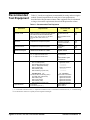
Table 2-3 is a form you can copy and use to record performance verification
test results for the multiplexer/expander. Information concerning test limits,
measurement uncertainty, and test accuracy ratio (TAR) is provided below.
Test limits are defined for VSWR using the specifications in Appendix A of
the Agilent E1472A User’s Manual or the Agilent E1474A User’s Manual.
The VSWR specifications are single-sided, (i.e., there is an upper limit but
no lower limit). In the Performance Test Record, the Minimum column is
blank.
Agilent E1472A/73A/74A/75A Service Manual
Verification Tests 33
Measurement
Uncertainty
For the performance verification tests in this manual, measurement
uncertainties are calculated based on an Agilent 8753C Network Analyzer
used with an Agilent 85046A 50 Ohm S-Parameter Test Set for the Agilent
E1472A/E1473A VSWR Test and an Agilent 85046B 75 Ohm S-Parameter
Test Set for the Agilent E1474A/E1475A VSWR Test. The measurement
uncertainty shown in Table 2-3 is computed using the 50 and 75 Ohm 3.5
mm connectors and the 3.5 mm CAL kit. The calculations follow.
VSWR Test
Assumptions:
• no change of temperature during the measurements
• all calculations are for a one-port test, all parameters related to port-2 are
set to 0.00
• calculations use typical parameters for the 3.5 mm CAL kit as provided
in the Agilent 85046C System Performance Manual and shown in Table
2-2
34 Verification Tests
Agilent E1472A/73A/74A/75A Service Manual
Table 2-2. Parameters used in Measurement Uncertainty Equations
Symbol
Error Term
Linear Value
@ 500 MHz
Linear Value
@ 1.3 GHz
D
Directivity
0.010
0.010
Tr
Reflection Tracking
0.016
0.016
Ms
Source Match
0.015
0.015
AM
Dynamic Accuracy (Magnitude)*
0.035
0.035
S11
S11**
1.250
1.350
Nl
Noise Floor
0.000
0.000
Nh
High Level Noise
0.00046
0.00046
Rr
Connector Reflection Repeatability
0.00032
0.00032
Rt
Connector Transmission Repeatability
0.00032
0.00032
Trd
Magnitude drift due to temperature
0.000
0.000
Sr1
Cable Reflection Stability
0.00032
0.00032
* Worst case Reference Power Level = 0 dbm
** S11 is a measured value, not an error term. The measurement uncertainty is calculated using the
maximum VSWR specification as the S11 term.
Measurement Uncertainty Equations Used
Yr = random port 1 repeatability = Rr1 + 2 ∗ Rt1 ∗ S11 + Rr1 ∗ S112
Xr = random high−level noise = 3 ∗ Nh ∗ S11
Wr = random low−level noise = 3 ∗ Nl
Sr = systematic error = D + Sr1 + Tr ∗ S11 + (Ms + Sr1 ) ∗ S112 + A m ∗ S11
√
Vr = Sr + W 2r + X 2r + Y 2r
Er (linear) = reflection uncertainty magnitude = Vr + S11 ∗ Trd (magnitude)
Agilent E1472A/73A/74A/75A Service Manual
Verification Tests 35
Measurement Uncertainty @ 500 MHz
Measurement Uncertainty is calculated using the values in Table 2-2 as
follows:
Yr = 0.00032 + 2 ∗ 0.00032∗1.250 + 0.00032 ∗ 1.2502 = 0.0016
Xr = 3 ∗ 0.00046 ∗ 1.250 = 0.0017
Wr = 3 ∗ 0.000 = 0.000
Sr = 0.010 + 0.00032 + 0.016 ∗ 1.250 + (0.015 + 0.00032) ∗ 1.2502 + 0.035 ∗ 1.250 = 0.0980
Vr = 0.0980 +
√
0.00162 + 0.0017
2
= 0.1003
M.U. = Er (linear) = 0.1003 + 1.250 ∗ 0.000 = 0.1003
Measurement Uncertainty @ 1.3 GHz
Measurement Uncertainty is calculated using the values in Table 2-2 as
follows:
Yr = 0.00032 + 2 ∗ 0.00032∗1.350 + 0.00032 ∗ 1.3502 = 0.0018
Xr = 3 ∗ 0.00046 ∗ 1.350 = 0.0019
Wr = 3 ∗ 0.000 = 0.000
Sr = 0.010 + 0.00032 + 0.016 ∗ 1.350 + (0.015 + 0.00032) ∗ 1.3502 + 0.035 ∗ 1.350 = 0.1071
Vr = 0.1071 +
√
0.00192 + 0.0018
2
= 0.1097
M.U. = Er (linear) = 0.1097 + 1.350 ∗ 0.000 = 0.1097
Test Accuracy
Ratio (TAR)
36 Verification Tests
Test Accuracy Ratios are not defined for single-sided measurements, so all
VSWR measurements have ’NA’ (Not Applicable) in the TAR column.
Agilent E1472A/73A/74A/75A Service Manual
Table 2-3. Performance Test Record (Page 1 of 3)
Model _______________________ Report No. ________________________ Date _________
General Information
Test Facility:
Name _____________________________________
Report No. _________________________________
Address
_____________________________________
Date _____________________________________
Customer ___________________________________
City/State ___________________________________
Tested by __________________________________
Phone _____________________________________
Special Notes:
_____________________________________________________________________________________________
_____________________________________________________________________________________________
____________________________________________________________________________________________
____________________________________________________________________________________________
____________________________________________________________________________________________
_____________________________________________________________________________________________
Test Equipment Used
Test Equipment Used:
Description
Model No.
Trace No.
Cal Due Date
1. _______________________________
_______________
_______________
_______________
2. _______________________________
_______________
_______________
_______________
3. _______________________________
_______________
______________
_______________
4. _______________________________
_______________
_______________
_______________
5. _______________________________
_______________
_______________
_______________
Agilent E1472A/73A/74A/75A Service Manual
Verification Tests 37
Table 2-3. Performance Test Record (Page 2 of 3)
Model _______________________ Report No. ________________________ Date _________
Test No/Description
Minimum*
Value
Measured Value
Maximum
Value
Meas
Uncert
Test Acc
Ratio (TAR)
Channel 00
Channel 01
Channel 02
Channel 03
___________________
___________________
___________________
___________________
1.25
1.25
1.25
1.25
1.003E-1
1.003E-1
1.003E-1
1.003E-1
NA
NA
NA
NA
Channel 10
Channel 11
Channel 12
Channel 13
___________________
___________________
___________________
___________________
1.25
1.25
1.25
1.25
1.003E-1
1.003E-1
1.003E-1
1.003E-1
NA
NA
NA
NA
Channel 20
Channel 21
Channel 22
Channel 23
___________________
___________________
___________________
___________________
1.25
1.25
1.25
1.25
1.003E-1
1.003E-1
1.003E-1
1.003E-1
NA
NA
NA
NA
Channel 30
Channel 31
Channel 32
Channel 33
___________________
___________________
___________________
___________________
1.25
1.25
1.25
1.25
1.003E-1
1.003E-1
1.003E-1
1.003E-1
NA
NA
NA
NA
Channel 40
Channel 41
Channel 42
Channel 43
___________________
___________________
___________________
___________________
1.25
1.25
1.25
1.25
1.003E-1
1.003E-1
1.003E-1
1.003E-1
NA
NA
NA
NA
Channel 50
Channel 51
Channel 52
Channel 53
___________________
___________________
___________________
___________________
1.25
1.25
1.25
1.25
1.003E-1
1.003E-1
1.003E-1
1.003E-1
NA
NA
NA
NA
2-1. VSWR Test
VSWR 100 MHz to
500 MHz
*Single-sided specification - Minimum value does not apply
38 Verification Tests
Agilent E1472A/73A/74A/75A Service Manual
Table 2-3. Performance Test Record (Page 3 of 3)
Model _______________________ Report No. ________________________ Date _________
Test No/Description
Minimum*
Value
Measured Value
Maximum
Value
Meas
Uncert
Test Acc
Ratio (TAR)
Channel 00
Channel 01
Channel 02
Channel 03
___________________
___________________
___________________
___________________
1.35
1.35
1.35
1.35
1.097E-1
1.097E-1
1.097E-1
1.097E-1
NA
NA
NA
NA
Channel 10
Channel 11
Channel 12
Channel 13
___________________
___________________
___________________
___________________
1.35
1.35
1.35
1.35
1.097E-1
1.097E-1
1.097E-1
1.097E-1
NA
NA
NA
NA
Channel 20
Channel 21
Channel 22
Channel 23
___________________
___________________
___________________
___________________
1.35
1.35
1.35
1.35
1.097E-1
1.097E-1
1.097E-1
1.097E-1
NA
NA
NA
NA
Channel 30
Channel 31
Channel 32
Channel 33
___________________
___________________
___________________
___________________
1.35
1.35
1.35
1.35
1.097E-1
1.097E-1
1.097E-1
1.097E-1
NA
NA
NA
NA
Channel 40
Channel 41
Channel 42
Channel 43
___________________
___________________
___________________
___________________
1.35
1.35
1.35
1.35
1.097E-1
1.097E-1
1.097E-1
1.097E-1
NA
NA
NA
NA
Channel 50
Channel 51
Channel 52
Channel 53
___________________
___________________
___________________
___________________
1.35
1.35
1.35
1.35
1.097E-1
1.097E-1
1.097E-1
1.097E-1
NA
NA
NA
NA
2-1. VSWR Test
VSWR 500 MHz to
1.3 GHz
*Single-sided specification - Minimum value does not apply
Agilent E1472A/73A/74A/75A Service Manual
Verification Tests 39
40 Verification Tests
Agilent E1472A/73A/74A/75A Service Manual
Chapter 3
Replaceable Parts
Introduction
Replaceable
Parts List
This chapter contains information for ordering replaceable parts for the
Agilent E1472A/74A RF Multiplexers and Agilent E1473A/75A RF
Multiplexer Expander modules.
Table 3-2 through 3-5 list replaceable parts for the multiplexers and
expanders. Table 3-6 shows reference designators for these parts, and Table
3-7 shows the manufacturer code list for these parts.
Exchange
Assemblies
Table 3-1 lists assemblies that may be replaced on an exchange basis.
Exchange assemblies are available only on a trade-in basis. Defective
assemblies must be returned for credit. Order assemblies for spare parts
stock by the new assembly part number.
Ordering
Information
To order a part listed in this chapter, specify the Agilent Technologies part
number and the quantity required. Send the order to your nearest
Agilent Technologies Sales and Support Office.
Agilent E1472A/73A/74A/75A Service Manual
Replaceable Parts 41
Table 3-1. Exchange/Replaceable Assemblies
Model
Assembly
Exchange PN
Replaceable PN
Agilent E1472A
A1
E1472-69501
E1472-66501
A2-A3
——————
E1472-66502
Agilent E1473A
A1-A2
——————
E1472-66502
Agilent E1474A
A1
E1472-69501
E1472-66501
A2-A3
——————
E1474-66502
Agilent E1475A
A1-A2
——————
E1474-66502
RMD Cable
3-to-1 Cable
E1472-61601
Table 3-2. Agilent E1472A Replaceable Parts
Reference Agilent Part Qty
Designator
Number
Part Description
Mfr.
Code
Mfr. Part
Number
50 OHM RF MULTIPLEXER ASSEMBLY
(See Figure 3-1)
A1
E1472-66501
1
PC ASSEMBLY RF COAX MUX
28480
F500-F503
2110-0712
4
FUSE-SUBMINIATURE 4A 125V NTD AX
75915
E1472-66501
R251004T1
A2-A3
E1472-66502
2
RELAY PRINTED CIRCUIT ASSEMBLY
28480
E1472-66502
CBL1
E1472-61601
1
CABLE-INTERCONNECT
28480
E1472-61601
1251-7584
3
CONNECTOR-POST TYPE .100-PIN-SPCG
20-CONTACT
18873
66900-220
1252-1371
1
CONNECTOR-POST TYPE .100-PIN-SPCG
60-CONTACT
18873
66900-260
8120-2981
1
CABLE-FLAT-RIBBON 28AWG 60-CNDCT
GRA-JKT
76381
3365-60
HDW1-HDW30
2950-0078
30
NUT-HEX-DBL-CHAM 10-32-THD .067-IN-THK
74163
500220
MNL1
E1472-90001
1
E1472A/E1473A USER’S MANUAL
28480
E1472-90001
MP1
E1300-45102
1
HANDLE KIT-BOTTOM, VXI
28480
E1300-45102
MP2
E1300-45101
1
HANDLE KIT-TOP, Agilent
28480
E1300-45101
MP3
8160-0686
1
RFI STRIP-FINGERS BE-CU TIN-PLATED
30817
00786-185
MP4
1400-0482
1
CABLE TIE .062-3-DIA .14-WD NYLON
59730
TY-26M-8
PNL1
E1472-00201
1
FRONT PANEL
28480
E1472-00201
SCR1-SCR2
0515-0368
2
SCREW-MACHINE M2.5 X 0.45 12MM-LG PAN-HD
28480
0515-0368
SCR3-SCR5
0515-0664
3
SCREW-MACHINE M3 X 0.5 12MM-LG PAN-HD
28480
0515-0664
SCR6-SCR13
0515-1135
8
SCREW-MACHINE M3 X 0.5 25MM-LG FLAT-HD
28480
0515-1135
SCR14-SCR17
0515-1375
4
SCREW-MACHINE M2.5 X 0.45 6MM-LG FLAT-HD
83486
343-300-02506
SCR18-SCR19
0515-1968
2
SCREW PH M2.5 X 11 TX
28480
0515-1968
42 Replaceable Parts
Agilent E1472A/73A/74A/75A Service Manual
Table 3-2. Agilent E1472A Replaceable Parts (Continued)
Reference Agilent Part Qty
Designator
Number
SHD1
SHD2
SHD3
WSH1-WSH30
Part Description
Mfr.
Code
Mfr. Part
Number
E1472-00601
1
SHIELD-TOP
28480
E1472-00601
0590-1893
8
THREADED INSERT-C’SINK-SPCR-NO THD
28480
0590-1893
E1472-00602
1
SHIELD
28480
E1472-00602
E1472-00603
1
SHIELD-BOTTOM
28480
E1472-00603
0590-1459
8
THREADED INSERT-STDF M3 X 0.5 6-MM-LG
46384
SOS-3.5M3-6
2190-0124
30
WASHER-LOCK INTL T NO. 10 .195-IN-ID
98291
3002-26
Table 3-3. Agilent E1473A Replaceable Parts
Reference Agilent Part Qty
Designator
Number
Part Description
Mfr.
Code
Mfr. Part
Number
50 OHM RF MULTIPLEXER EXPANDER
ASSEMBLY (See Figure 3-2)
A1-A2
E1472-66502
2
RELAY PRINTED CIRCUIT ASSEMBLY
28480
E1472-66502
CBL1
E1472-61601
1
CABLE-INTERCONNECT
28480
E1472-61601
1251-7584
3
CONNECTOR-POST TYPE .100-PIN-SPCG
20-CONTACT
18873
66900-220
1252-1371
1
CONNECTOR-POST TYPE .100-PIN-SPCG
60-CONTACT
18873
66900-260
8120-2981
1
CABLE-FLAT-RIBBON 28AWG 60-CNDCT
GRA-JKT
76381
3365-60
2950-0078
30
NUT-HEX-DBL-CHAM 10-32-THD .067-IN-THK
74163
500220
HDW1-HDW30
MP1
E1300-45102
1
HANDLE KIT-BOTTOM, VXI
28480
E1300-45102
MP2
E1300-45101
1
HANDLE KIT-TOP, Agilent
28480
E1300-45101
MP3
8160-0686
1
RFI STRIP-FINGERS BE-CU TIN-PLATED
30817
00786-185
PNL1
E1473-00201
1
FRONT PANEL
28480
E1473-00201
SCR1-SCR2
0515-0368
2
SCREW-MACHINE M2.5 X 0.45 12MM-LG PAN-HD
28480
0515-0368
SCR3-SCR7
0515-0375
5
SCREW-MACHINE M3 X 0.5 16MM-LG PAN-HD
28480
0515-0375
SCR8-SCR10
0515-1135
3
SCREW-MACHINE M3 X 0.5 25MM-LG FLAT-HD
28480
0515-1135
SCR11-SCR12
0515-1375
2
SCREW-MACHINE M2.5 X 0.45 6MM-LG FLAT-HD
83486
343-300-02506
SCR13-SCR14
0515-1968
2
SCREW PH M2.5 X 11 TX
28480
0515-1968
SHD1
E1472-00602
1
SHIELD
28480
E1472-00602
SHD2
E1472-00601
1
SHIELD-TOP
28480
E1472-00601
0590-1893
8
THREADED INSERT-C’SINK-SPCR-NO THD
28480
0590-1893
E1472-00603
1
SHIELD-BOTTOM
28480
E1472-00603
0590-1459
8
THREADED INSERT-STDF M3 X 0.5 6-MM-LG
46384
SOS-3.5M3-6
2190-0124
30
WASHER-LOCK INTL T NO. 10 .195-IN-ID
98291
3002-26
SHD3
WSH1-WSH30
Agilent E1472A/73A/74A/75A Service Manual
Replaceable Parts 43
Table 3-4. Agilent E1474A Replaceable Parts
Reference Agilent Part Qty
Designator
Number
Part Description
Mfr.
Code
Mfr. Part
Number
75 OHM RF MULTIPLEXER ASSEMBLY
(See Figure 3-1)
A1
E1472-66501
1
PC ASSEMBLY RF COAX MUX
28480
E1472-66501
F500-F503
2110-0712
4
FUSE-SUBMINIATURE 4A 125V NTD AX
75915
R251004T1
A2-A3
E1474-66502
2
PC ASSEMBLY 75 OHM MULTIPLEXER
28480
E1474-66502
CBL1
E1472-61601
1
CABLE-INTERCONNECT
28480
E1472-61601
1251-7584
3
CONNECTOR-POST TYPE .100-PIN-SPCG
20-CONTACT
18873
66900-220
1252-1371
1
CONNECTOR-POST TYPE .100-PIN-SPCG
60-CONTACT
18873
66900-260
8120-2981
1
CABLE-FLAT-RIBBON 28AWG 60-CNDCT
GRA-JKT
76381
3365-60
2950-0078
30
NUT-HEX-DBL-CHAM 10-32-THD .067-IN-THK
74163
500220
HDW1-HDW30
MNL1
E1474-90001
1
E1474A/E1475A USER’S MANUAL
28480
E1474-90001
MP1
E1300-45102
1
HANDLE KIT-BOTTOM, VXI
28480
E1300-45102
MP2
E1300-45101
1
HANDLE KIT-TOP, Agilent
28480
E1300-45101
MP3
8160-0686
1
RFI STRIP-FINGERS BE-CU TIN-PLATED
30817
00786-185
MP4
1400-0482
1
CABLE TIE .062-3-DIA .14-WD NYLON
59730
TY-26M-8
PNL1
E1474-00201
1
FRONT PANEL
28480
E1474-00201
SCR1-SCR2
0515-0368
2
SCREW-MACHINE M2.5 X 0.45 12MM-LG PAN-HD
28480
0515-0368
SCR3-SCR5
0515-0664
3
SCREW-MACHINE M3 X 0.5 12MM-LG PAN-HD
28480
0515-0664
SCR6-SCR13
0515-1135
8
SCREW-MACHINE M3 X 0.5 25MM-LG FLAT-HD
28480
0515-1135
SCR14-SCR17
0515-1375
4
SCREW-MACHINE M2.5 X 0.45 6MM-LG FLAT-HD
83486
343-300-02506
SCR18-SCR19
0515-1968
2
SCREW PH M2.5 X 11 TX
28480
0515-1968
SHD1
E1474-00601
1
SHIELD-TOP
28480
E1474-00601
0590-1893
8
THREADED INSERT-C’SINK-SPCR-NO THD
28480
0590-1893
SHD2
E1472-00602
1
SHIELD
28480
E1472-00602
SHD3
E1472-00603
1
SHIELD-BOTTOM
28480
E1472-00603
0590-1459
8
THREADED INSERT-STDF M3 X 0.5 6-MM-LG
46384
SOS-3.5M3-6
2190-0124
30
WASHER-LOCK INTL T NO. 10 .195-IN-ID
98291
3002-26
WSH1-WSH30
44 Replaceable Parts
Agilent E1472A/73A/74A/75A Service Manual
Table 3-5. Agilent E1475A Replaceable Parts
Reference Agilent Part Qty
Designator
Number
Part Description
Mfr.
Code
Mfr. Part
Number
75 OHM RF MULTIPLEXER EXPANDER
ASSEMBLY (See Figure 3-2)
A1-A2
E1474-66502
2
PC ASSEMBLY 75 OHM MULTIPLEXER
28480
E1474-66502
CBL1
E1472-61601
1
CABLE-INTERCONNECT
28480
E1472-61601
1251-7584
3
CONNECTOR-POST TYPE .100-PIN-SPCG
20-CONTACT
18873
66900-220
1252-1371
1
CONNECTOR-POST TYPE .100-PIN-SPCG
60-CONTACT
18873
66900-260
8120-2981
1
CABLE-FLAT-RIBBON 28AWG 60-CNDCT
GRA-JKT
76381
3365-60
HDW1-HDW30
2950-0078
30
NUT-HEX-DBL-CHAM 10-32-THD .067-IN-THK
74163
500220
MP1
E1300-45102
1
HANDLE KIT-BOTTOM, VXI
28480
E1300-45102
MP2
E1300-45101
1
HANDLE KIT-TOP, Agilent
28480
E1300-45101
MP3
8160-0686
1
RFI STRIP-FINGERS BE-CU TIN-PLATED
30817
00786-185
PNL1
E1475-00201
1
FRONT PANEL
28480
E1475-00201
SCR1-SCR2
0515-0368
2
SCREW-MACHINE M2.5 X 0.45 12MM-LG PAN-HD
28480
0515-0368
SCR3-SCR7
0515-0375
5
SCREW-MACHINE M3 X 0.5 16MM-LG PAN-HD
28480
0515-0375
SCR8-SCR10
0515-1135
3
SCREW-MACHINE M3 X 0.5 25MM-LG FLAT-HD
28480
0515-1135
SCR11-SCR12
0515-1375
2
SCREW-MACHINE M2.5 X 0.45 6MM-LG FLAT-HD
83486
343-300-02506
SCR13-SCR14
0515-1968
2
SCREW PH M2.5 X 11 TX
28480
0515-1968
SHD1
E1472-00602
1
SHIELD
28480
E1472-00602
SHD2
E1475-00601
1
SHIELD-TOP
28480
E1475-00601
0590-1893
3
THREADED INSERT-C’SINK-SPCR-NO THD
28480
0590-1893
E1473-00603
1
SHIELD-BOTTOM
28480
E1473-00603
0590-1367
5
THREADED INSERT-STDF M3 X 0.5 10-MM-LG
46384
SOS-3.5M3-10
0590-1459
3
THREADED INSERT-STDF M3 X 0.5 6-MM-LG
46384
SOS-3.5M3-6
2190-0124
30
WASHER-LOCK INTL T NO. 10 .195-IN-ID
98291
3002-26
SHD3
WSH1-WSH30
Agilent E1472A/73A/74A/75A Service Manual
Replaceable Parts 45
Table 3-6. Agilent E1472A/73A/74A/75A Reference Designators
Reference Designators
A .................. assembly
PCB ............ printed circuit board
BRK.............. bracket
PNL ............. panel
C .................. capacitor
Q ................. transistor
CR................ diode
R ................. resistor
CS ................case
RP ............... resistor pack
CVR ............. cover
RT ............... thermistor probe
F................... fuse
SCR ............. screw
J ................... electrical connector (jack)
SHD ............ shield
JM ................ jumper
SW .............. switch
K ..................relay
TB ............... terminal block
MP................mechanical part
U ................. integrated circuit
P .................. electrical connector (plug)
Table 3-7. Agilent E1372A/73A/74A/75A Code List of Manufacturers
Mfr.
Code
46 Replaceable Parts
Manufacturer’s
Name
Manufacturer’s
Address
Zip
Code
18873
DUPONT E I DE NEMOURS & CO
WILMINGTON DE US
19801
28480
AGILENT TECHNOLOGIES CORPORATE
PALO ALTO CA US
94304
18327
30817
INSTRUMENT SPECIALTIES CO INC
DEL WATER GAP PA US
46384
PENN ENGINEERING & MFG CORP
DOYLESTOWN PA US
18901
59730
THOMAS & BETTS CORP
RARITAN NJ US
08869
74163
PHELPS DODGE CORP
NEW YORK NY US
10022
75915
LITTELFUSE INC
DES PLAINES IL US
60016
76381
3M CO
ST PAUL MN US
55144
83486
ELCO INDUSTRIES INC
ROCKFORD IL US
61125
98291
ITT SEALECTRO CORP
TRUMBULL CT US
06611
Agilent E1472A/73A/74A/75A Service Manual
Figure 3-1. Agilent E1472A & E1474A Replaceable Parts
Agilent E1472A/73A/74A/75A Service Manual
Replaceable Parts 47
Figure 3-2. Agilent E1473A & E1475A Replaceable Parts
48 Replaceable Parts
Agilent E1472A/73A/74A/75A Service Manual
Chapter 4
Service
Introduction
WARNING
Repair Strategy
This chapter contains service information for the Agilent
E1472A/73A/74A/75A RF Multiplexer/Expander modules, including repair
strategy, troubleshooting techniques and repair/maintenance guidelines.
Do not perform any of the service procedures shown unless
you are a qualified, service-trained technician, and have read
the WARNINGS and CAUTIONS in Chapter 1.
Procedures in this chapter describe troubleshooting techniques for the
Agilent E1472A/E1474A RF Multiplexers and Agilent E1473A/E1475A RF
Multiplexer Expanders. The VXI interface, relay decoders and relay drivers
are all contained on a single PC board in the Agilent E1472A or Agilent
E1474A RF Multiplexer. This PC board should be replaced as an exchange
assembly. Exchange assembly part numbers are contained in Chapter 3 Replaceable Parts.
The multiplexer relays, tree relays, and their associated RF connectors are
contained on separate PC boards. The Relay Assembly PC board (Agilent PN
E1472-66502 or E1474-66502) is available only as a replaceable part (not an
exchange assembly). Each Relay Assembly PC Board contains three banks of
channels. Two complete Relay Assembly PC Boards are contained in each
Agilent E1472A/E1473A/E1474A/E1475A module.
Equipment
Required
Equipment required for multiplexer/expander troubleshooting and repair is
listed in Table 1-1, Recommended Test Equipment. Any equipment that
satisfies the requirements given in the table may be substituted.
To avoid damage to the screw head slots, use a T8 Torx driver to remove
the front panel handles and a T10 Torx driver to remove the shields.
Agilent E1472A/73A/74A/75A Service Manual
Service 49
Service Aids
Troubleshooting
Identifying
the Problem
See Chapter 3 for descriptions and locations of Agilent
E1472A/73A/74A/75A mechanical replaceable parts. Service notes, manual
updates, and service literature for the modules may be available through
Agilent Technologies. For information, contact your nearest Agilent
Technologies Sales and Support Office.
The troubleshooting information and procedures in this section will help
isolate a problem to an assembly.
Table 4-1 lists some common problems, along with symptoms and possible
solutions.
Table 4-1. Agilent E1472A/73A/74A/75A Common Problems
Problem
Type
Self-test Errors
Operator Errors
Symptom
Possible
Solutions
Non-zero error code in response to
the *TST? command.
See Table 4-3 for information on
self-test errors.
Incorrect response to SYST:COPT?
command.
See "Isolating to an Assembly" in this
chapter.
Non-zero error code in response to
the SYST:ERR? command.
See Appendix C of the the Agilent
E1472A/E1473A User’s Manual or
Agilent E1474A/E1475A User’s
Manual for RF multiplexer errors and
causes.
See Appendix B of the
Agilent E1405 User’s Manual for
additional information on operator
errors.
Catastrophic
Failures
Performance Out
of Specification
Not responding to commands.
Check logical address setting.
Check GPIB cables and connections.
Failing Functional Verification Test
(Chapter 2)
Check RMD cables and connectors.
Failing VSWR Test (see Test 2-1 in
Chapter 2).
Check user wiring and test
connections.
If channels are near or above the test
limit, replace the printed circuit board
(Agilent PN E1472-66502 or
E1474-66502).
50 Service
Agilent E1472A/73A/74A/75A Service Manual
Testing the
Assembly
You can use the tests and checks in Table 4-2 to isolate the problem. See
Figures 3-1 and 3-2 in Chapter 3 for locations of mechanical parts.
Table 4-2. Agilent E1472A/73A/74A/75A Tests/Checks
Test/Check
Reference Designator
Check:
Heat Damage
----------
Discolored PC boards
Damaged insulation
Evidence of arcing
Switch/Jumper
Settings
J100, J101
SP1
J200
IRQ Level setting
LADDR setting
Relay Drive Level
RF Multiplexer
PCA
F501, F502, F503, F504
P200, P400, P500, P501
Fuse continuity
Connector contacts
Relay Assembly
PCA
P1
A2 - A3
Connector Contacts
Test 2-1, VSWR Test
Checking for Heat Damage
Inspect the assembly for signs of abnormal internally generated heat such as
discolored printed circuit boards or components, damaged insulation, or
evidence of arcing.
Checking Switches/Jumpers
Verify that the logical address switch is set correctly (factory set at 120).
Verify that the interrupt priority jumpers are set correctly (factory set at
level 1). Verify the Relay Drive Level is set correctly (factory set at +12
Vdc). Refer to the Agilent E1472A/E1473A User’s Manual or Agilent
E1474A/E1475A User’s Manual for procedures to set or check these
switches/jumpers.
Checking the RF Multiplexer PCA
Check the following:
• Verify that fuses F501, F502, F503, and F504 are good.
• Check connectors P200, P400, P500, and P501 for damage.
• Perform Test 2-1 in Chapter 2. Replace Relay Assembly PC for failing
channels.
Checking the Relay Assembly PCA
Check the following:
• Check connector contacts P1.
• Perform Test 2-1 in Chapter 2. Replace Relay Assembly PC for failing
channels.
Agilent E1472A/73A/74A/75A Service Manual
Service 51
Isolating to an
Assembly
Figure 4-1 is a simplified diagram of the multiplexer and two multiplexer
expanders. For this configuration, up to six relay assemblies can be driven
by a single control assembly. The relay assemblies must be driven in pairs
and both RMD cables must be connected to the relay assemblies for the
assembly to be recognized using the SYST:COPT? command (See
Expander Functional Verification - Chapter 2).
Figure 4-1. Multiplexer/Expander Simplified Diagram
52 Service
Agilent E1472A/73A/74A/75A Service Manual
Self-test
Error Codes
Table 4-3 shows the self-test error codes for the multiplexer modules. The
meaning of each code is given in the right-hand column. If a self-test failure
occurs, cycle power and repeat the test. If the problem reoccurs, the device
may need repair.
Table 4-3. Self-test Error Codes
Error*
+0
+ss01
+ss02
+ss03
+ss10
+ss11
Description
Self-test passes
Firmware error
Bus error (communications problem with card)
Bad ID information in ID register
Interrupt expected but not received
Busy bit was not held ≈10.5 to 18.5 msec
*ss = card number (with leading zero deleted)
Procedure
1. Verify that the multiplexer is installed in the mainframe and that the
mainframe has passed its power-on test.
2. Send the *TST? command to the device (see example following).
3. The device will return an error code. Any non-zero error code
indicates a self-test failure. See Table 4-3 for a description of self-test
error codes.
Example
An example follows which uses an HP 9000 Series 300 computer with
BASIC and an multiplexer address of 70915.
10 OUTPUT 70915;"*TST?"
Send the self-test command
20 ENTER 70915;A
Get response
30 PRINT A
40 END
Agilent E1472A/73A/74A/75A Service Manual
Service 53
Disassembly
RF Multiplexer
Disassembly
Use the following procedures to disassemble the Agilent E1472A/E1474A
RF Multiplexer or Agilent E1473A/E1475A RF Multiplexer Expander
module. For disassembly refer to Figures 4-2 and 4-3.
1. To remove the covers:
• Remove all 30 nuts and washers from the RF connectors as shown.
• Remove the eight T10 Torx screws from the top cover as shown.
• Lift the top cover off the module. The cover may be a tight fit
around the RF Connectors.
• Turn the assembly over and lift off the bottom cover. The cover
may be a tight fit around the RF Connectors.
2. To remove the A2 and A3 Assemblies:
• Remove the 3-to-1 cable from the A1, A2, and A3 assemblies.
• Remove the three T10 Torx screws from the relay assembly PC
board as shown.
• Lift the top Relay Assembly out.
• Lift the shield out as shown.
• Lift the bottom Relay Assembly out.
3. To remove the front panel:
• Remove the two T8 Torx screws from handles MP1 and MP2 as
shown.
• Remove the two T8 Torx screws holding the panel to the A1 PC
Assembly as shown.
• Lift the front panel from the A1 assembly.
54 Service
Agilent E1472A/73A/74A/75A Service Manual
Figure 4-2. Agilent E1472A/E1474A Disassembly
Agilent E1472A/73A/74A/75A Service Manual
Service 55
RF Multiplexer
Expander Disassembly
1. To remove the covers:
• Remove all 30 nuts and washers from the RF connectors as shown.
• Remove the three T10 Torx screws from the top cover as shown.
• Lift the top cover off of the module. The cover may be a tight fit
around the RF Connectors.
• Turn the assembly over and lift off the bottom cover. The cover
may be a tight fit around the RF Connectors.
2. To remove the A1 and A2 Assemblies:
• Remove the three T10 Torx screws from the relay assembly PC
board as shown.
• Lift the top Relay Assembly out.
• Lift the shield out as shown.
• Lift the bottom Relay Assembly out.
Figure 4-3. Agilent E1473A/E1475A Disassembly
56 Service
Agilent E1472A/73A/74A/75A Service Manual
Repair/
Maintenance
Guidelines
ESD
Precautions
This section provides guidelines for repairing and maintaining the Agilent
E1472A/73A/74A/75A RF Multiplexer/Expander modules, including:
• ESD precautions
• Soldering printed circuit boards
• Post-repair safety checks
Electrostatic discharge (ESD) may damage static-sensitive devices in the
multiplexer/expander modules. This damage can range from slight parameter
degradation to catastrophic failure. When handling multiplexer/expander
assemblies, follow these guidelines to avoid damaging components:
• Always use a static-free work station with a pad of conductive rubber or
similar material when handling electronic components.
• Do not use pliers to remove a MOS or CMOS device from a high-grip
socket. Instead, use a small screwdriver to pry the device up from one
end. Slowly lift the device up, one pair of pins at a time.
• After you remove a MOS or CMOS device from a module, place the
device onto a pad of conductive foam or other suitable holding material.
• If a device requires soldering, be sure the assembly is placed on a pad of
conductive material. Also, be sure that you, the pad, and the soldering
iron tip are grounded to the assembly.
Soldering Printed
Circuit Boards
The etched circuit boards in the multiplexer/expander modules have plated-through
holes that allow a solder path to both sides of the insulating material. Soldering can
be done from either side of the board with equally good results. When soldering to
any circuit board, keep in mind the following guidelines:
• The relays used on these printed circuit boards require special soldering
techniques and equipment. The use of a solder-pot is recommended for
relay removal and replacement.
• Do not use a high power soldering iron on etched circuit boards, as
excessive heat may lift a conductor or damage the board.
• Use a suction device or wooden toothpick to remove solder from
component mounting holes. When using a suction device, be sure that the
equipment is properly grounded.
Post-Repair
Safety Checks
After making repairs to the module, inspect the device for any signs of
abnormal internally generated heat, such as discolored printed circuit boards
or components, damaged insulation, or evidence of arcing. Determine and
correct the cause of the condition. Then perform the Functional Verification
Test described in Chapter 2 to verify that the device is functional.
Agilent E1472A/73A/74A/75A Service Manual
Service 57
58 Service
Agilent E1472A/73A/74A/75A Service Manual
Chapter A
Verification Tests - C Programs
Functional
Verification
Tests
These programs are designed to do the Functional Verification Tests found
in Chapter 2 - Verification Tests.
Example:
Multiplexer Self
Test
NOTE
The Functional Verification Test for the Agilent E1472A and E1474A RF
Multiplexers consists of sending the *TST? command and checking the
response. This test can be used to verify that the multiplexer is connected
properly and is responding to a basic command.
This program assumes a primary address of 09 and a secondary address of
15. If your Multiplexer address does not match this, you must either
change the Multiplexers address setting or change the program line
#define ADDR "hpib7,9,15" to match your Multiplexers address setting.
#include <stdio.h>
#include <sicl.h>
#define ADDR "hpib7,9,15"
/* Address of device */
main ()
{
INST id;
char a[256] = {0};
id = iopen (ADDR);
/* Define id as an instrument */
/* Result variable */
/* Open instrument session */
ipromptf(id, "*TST?\n", "%t", a);
printf("\n %s", a);
getchar();
/* Self test command */
/* Print result */
/* Pause */
iclose (id);
/* Close instrument session */
}
Agilent E1472A/73A/74A/75A Service Manual
Example C Programs 59
Example:
Expander Self Test
The Functional Verification Test for the Agilent E1473A and E1475A RF
Multiplexer Expanders consists of sending the :COPTion? query command
and checking the response. This test can be used to verify that the device is
connected properly and is responding to basic commands.
#include <stdio.h>
#include <sicl.h>
#define ADDR "hpib7,9,15"
/* Address of device */
main ()
{
INST id;
char a[256] = {0};
id = iopen (ADDR);
/* Define id as an instrument */
/* Result variable */
/* Open instrument session */
ipromptf(id, "SYST:COPT? 1\n", "%t", a);
printf("\n %s", a);
getchar();
/* Self test command */
/* Print result */
/* Pause */
iclose (id);
/* Close instrument session */
}
60 Example C Programs
Agilent E1472A/73A/74A/75A Service Manual
Performance
Verification
Test
This program is designed to do the Performance Verification Test found in
Chapter 2 - Verification Tests.
NOTE
This program assumes a primary address of 09 and a secondary address of
15. If your Multiplexer address does not match this, you must either
change the Multiplexers address setting or change the program lines
#define ADDR "hpib7,9,15" to match your Multiplexers address setting.
Example: VSWR
Test
This example performs a VSWR Test on all channels in the RF Multiplexer.
If a channel is out of specification, the program prints a message and pauses.
/* VSWR Test
E1366A */
#include <stdio.h>
#include <sicl.h>
#define ADDR "hpib7,9,15"
void main (void)
{
INST id, dm;
double result[4][12];
int i, k, Mm, tst;
/* Address of device */
/* Define id and dm as an instrument */
#if defined(__BORLANDC__) && !defined(__WIN32__)
_InitEasyWin();
#endif
ionerror(I_ERROR_EXIT);
id = iopen (ADDR);
/* Open instrument session */
RETRY:
printf ("\n\nSelect the test to run");
printf ("\n\n Test 1. RF Multiplexer (Agilent E1472A or E1474A)");
printf ("\n Test 2. RF Multiplexer Expander (Agilent E1473A or E1475A)");
printf ("\nEnter the test number (1 or 2) ");
scanf ("%u", tst);
if (tst == 1) Mm = 0;
if (tst == 2) Mm = 1;
if (!(tst==1) && !(tst==2)) goto RETRY;
printf ("\n\nEquipment Setup");
Agilent E1472A/73A/74A/75A Service Manual
Example C Programs 61
printf ("\n\n 1. Turn Network Analyzer power ON, allow a one hour warm-up");
printf ("\n 2. Install Agilent E1472A or E1474A Component Assembly into
Mainframe.");
if (tst == 2)
printf ("\n 2a. Install Agilent E1473A or E1475A Expander");
printf ("\n 3. Turn Mainframe power ON");
printf ("\n 4. Press ENTER when ready to begin testing.");
getchar ();
printf ("\n\nCalibrate the Network Analyzer");
printf ("\n\n 1. Press PRESET");
printf ("\n 2. Select SWR measurement type from FORMAT menu");
printf ("\n 3. Set the START frequency to 100 MHz");
printf ("\n 4. Set the STOP frequency to 500 MHz");
printf ("\n 5. Select the 3.5 mm CAL kit");
printf ("\n 6. Calibrate the test port and cable for OPEN, SHORT, and LOAD");
printf ("\n 7. Set the scale to 100 mV/DIV");
printf ("\n 8. Press ENTER when ready to begin testing");
getchar ();
/*--------------------100 - 500 MHz Test----------------------------*/
iprintf (id, "*RST\n");
for (k = 0; k <= 5; k++)
{
printf ("\n\nVSWR from 100 MHz to 500 MHz");
for (i = 0; i <= 3; i++)
{
printf ("\n\n 1. Connect test port cable to COM %u0", k);
printf ("\n 2. Connect LOAD to channel %u%u", k, i);
printf ("\n 3. Press ENTER when connections are complete");
getchar ();
iprintf (id, "CLOS (@10%u%u%u)\n", Mm, k, i);
printf ("\n\nObserve the Network Analyzer display");
printf ("\n Enter the highest measured VSWR reading: ");
scanf ("%lf", &result[i][k]);
iprintf (id, "OPEN (@10%u%u%u)\n", Mm, k, i);
if (result[i][k] > 1.25)
{
printf ("\n\n*** Channel %u%u FAILED - VSWR 1.25", k, i);
printf ("\n Press ENTER to test next channel");
getchar ();
}
}
}
printf ("\n\n100 MHz to 500 MHz VSWR Test complete");
printf ("\n Press ENTER for 500 MHz to 1.3 GHz test");
getchar ();
62 Example C Programs
Agilent E1472A/73A/74A/75A Service Manual
/*--------------------500 MHz - 1.3 GHz Test------------------------*/
printf ("\n\nEquipment Setup");
printf ("\n\n 1. Turn Network Analyzer power ON, allow a one hour warm-up");
printf ("\n 2. Install Agilent E1472A or E1474A Component Assembly into
Mainframe.");
if (tst == 2)
printf ("\n 2a. Install Agilent E1473A or E1475A Expander");
printf ("\n 3. Turn Mainframe power ON");
printf ("\n 4. Press ENTER when ready to begin testing.");
getchar ();
printf ("\n\nCalibrate the Network Analyzer");
printf ("\n\n 1. Press PRESET");
printf ("\n 2. Select SWR measurement type from FORMAT menu");
printf ("\n 3. Set the START frequency to 500 MHz");
printf ("\n 4. Set the STOP frequency to 1.3 GHz");
printf ("\n 5. Select the 3.5 mm CAL kit");
printf ("\n 6. Calibrate the test port and cable for OPEN, SHORT, and LOAD");
printf ("\n 7. Set the scale to 100 mV/DIV");
printf ("\n 8. Press ENTER when ready to begin testing");
getchar ();
iprintf (id, "*RST\n");
for (k = 0; k <= 5; k++)
{
printf ("\n\nVSWR from 500 MHz to 1.3 GHz");
for (i = 0; i <= 3; i++)
{
printf ("\n\n 1. Connect test port cable to COM %u0", k);
printf ("\n 2. Connect LOAD to channel %u%u", k, i);
printf ("\n 3. Press ENTER when connections are complete");
getchar ();
iprintf (id, "CLOS (@10%u%u%u)\n", Mm, k, i);
printf ("\n\nObserve the Network Analyzer display");
printf ("\n Enter the highest measured VSWR reading: ");
scanf ("%lf", &result[i][k+6]);
iprintf (id, "OPEN (@10%u%u%u)\n", Mm, k, i);
if (result[i][k+2] > 1.35)
{
printf ("\n\n*** Channel %u%u FAILED - VSWR 1.35", k, i);
printf ("\n Press ENTER to test next channel");
getchar ();
}
}
}
Agilent E1472A/73A/74A/75A Service Manual
Example C Programs 63
printf ("\n\n500 MHz to 1.3 GHz VSWR Test complete");
printf ("\n Press ENTER to display measurement results");
getchar ();
/*--------------------Display Measurement Results-------------------*/
printf ("\n\n-----------------------------------------------------------");
printf ("\n
100 MHz to 500 MHz 500 MHz to 1.3 GHz\n");
for (k = 0; k <= 5; k++)
for (i = 0; i <= 3; i++)
printf ("\nChannel %u%u VSWR = %18lf
iclose (id);iclose (dm);
%18lf", k, i, result[i][k], result[i][k+6]);
/* Close instrument session */
}
64 Example C Programs
Agilent E1472A/73A/74A/75A Service Manual