1
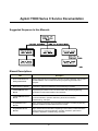
Agilent 75000 SERIES C
Agilent E1446A
Summing Amplifier/DAC Module
Service Manual
Copyright© Agilent Technologies, Inc., 1993 - 2006
*E1446-90010*
E1446-90010
E0706
Manual Part Number: E1446-90010
Printed: July 2006 Edition 2 Rev 2
Printed in Malaysia E0706
Certification
Agilent Technologies certifies that this product met its published specifications at the time of shipment from the factory. Agilent
Technologies further certifies that its calibration measurements are traceable to the United States National Institute of Standards and
Technology (formerly National Bureau of Standards), to the extent allowed by that organization’s calibration facility, and to the calibration
facilities of other International Standards Organization members.
Warranty
This Agilent Technologies product is warranted against defects in materials and workmanship for a period of one (1) year from date of
shipment. Duration and conditions of warranty for this product may be superseded when the product is integrated into (becomes a part
of) other Agilent products. During the warranty period, Agilent Technologies will, at its option, either repair or replace products which
prove to be defective.
For warranty service or repair, this product must be returned to a service facility designated by Agilent Technologies. Buyer shall prepay
shipping charges to Agilent and Agilent shall pay shipping charges to return the product to Buyer. However, Buyer shall pay all shipping
charges, duties, and taxes for products returned to Agilent from another country.
Agilent warrants that its software and firmware designated by Agilent for use with a product will execute its programming instructions
when properly installed on that product. Agilent does not warrant that the operation of the product, or software, or firmware will be
uninterrupted or error free.
Limitation Of Warranty
The foregoing warranty shall not apply to defects resulting from improper or inadequate maintenance by Buyer, Buyer-supplied products
or interfacing, unauthorized modification or misuse, operation outside of the environmental specifications for the product, or improper site
preparation or maintenance.
The design and implementation of any circuit on this product is the sole responsibility of the Buyer. Agilent does not warrant the Buyer’s
circuitry or malfunctions of Agilent products that result from the Buyer’s circuitry. In addition, Agilent does not warrant any damage that
occurs as a result of the Buyer’s circuit or any defects that result from Buyer-supplied products.
NO OTHER WARRANTY IS EXPRESSED OR IMPLIED. Agilent SPECIFICALLY DISCLAIMS THE IMPLIED WARRANTIES
OF MERCHANTABILITY AND FITNESS FOR A PARTICULAR PURPOSE.
Exclusive Remedies
THE REMEDIES PROVIDED HEREIN ARE BUYER’S SOLE AND EXCLUSIVE REMEDIES. Agilent SHALL NOT BE LIABLE
FOR ANY DIRECT, INDIRECT, SPECIAL, INCIDENTAL, OR CONSEQUENTIAL DAMAGES, WHETHER BASED ON CONTRACT, TORT, OR ANY OTHER LEGAL THEORY.
Notice
The information contained in this document is subject to change without notice. Agilent Technologies MAKES NO WARRANTY OF
ANY KIND WITH REGARD TO THIS MATERIAL, INCLUDING, BUT NOT LIMITED TO, THE IMPLIED WARRANTIES OF
MERCHANTABILITY AND FITNESS FOR A PARTICULAR PURPOSE. Agilent shall not be liable for errors contained herein or for
incidental or consequential damages in connection with the furnishing, performance or use of this material. This document contains
proprietary information which is protected by copyright. All rights are reserved. No part of this document may be photocopied, reproduced,
or translated to another language without the prior written consent of Agilent Technologies, Inc. Agilent assumes no responsibility for the
use or reliability of its software on equipment that is not furnished by Agilent.
U.S. Government Restricted Rights
The Software and Documentation have been developed entirely at private expense. They are delivered and licensed as "commercial
computer software" as defined in DFARS 252.227- 7013 (Oct 1988), DFARS 252.211-7015 (May 1991) or DFARS 252.227-7014 (Jun
1995), as a "commercial item" as defined in FAR 2.101(a), or as "Restricted computer software" as defined in FAR 52.227-19 (Jun 1987)(or
any equivalent agency regulation or contract clause), whichever is applicable. You have only those rights provided for such Software and
Documentation by the applicable FAR or DFARS clause or the Agilent standard software agreement for the product involved.
Agilent E1446A Summing Amplifier/DAC Module Service Manual
Edition 1 Rev 2
Copyright © 1993-2006 Agilent Technologies, Inc. All Rights Reserved.
i
Printing History
The Printing History shown below lists all Editions and Updates of this manual and the printing date(s). The first printing of the manual
is Edition 1. The Edition number increments by 1 whenever the manual is revised. Updates, which are issued between Editions, contain
replacement pages to correct the current Edition of the manual. Updates are numbered sequentially starting with Update 1. When a new
Edition is created, it contains all the Update information for the previous Edition. Each new Edition or Update also includes a revised copy
of this printing history page. Many product updates or revisions do not require manual changes and, conversely, manual corrections may
be done without accompanying product changes. Therefore, do not expect a one-to-one correspondence between product updates and
manual updates.
Edition 1 (Part Number E1446-90010). . . . . . . . . . . . . . . . . . . . . . January 1993
Edition 1 Rev 2 (Part Number E1446-90010) . . . . . . . . . . . . . . . . . . . July 2006
Safety Symbols
Instruction manual symbol affixed to product.
Indicates that the user must refer to the manual for specific WARNING or CAUTION
information to avoid personal injury or damage to the product.
Alternating current (AC).
Direct current (DC).
Indicates hazardous voltages.
Indicates the field wiring terminal that must
be connected to earth ground before operating
the equipment—protects against electrical
shock in case of fault.
or
WARNING
Frame or chassis ground terminal—typically
connects to the equipment’s metal frame.
CAUTION
Calls attention to a procedure, practice, or condition that could cause bodily injury or death.
Calls attention to a procedure, practice, or condition that could possibly cause damage to
equipment or permanent loss of data.
WARNINGS
The following general safety precautions must be observed during all phases of operation, service, and repair of this product.
Failure to comply with these precautions or with specific warnings elsewhere in this manual violates safety standards of design,
manufacture, and intended use of the product. Agilent Technologies assumes no liability for the customer’s failure to comply with
these requirements.
Ground the equipment: For Safety Class 1 equipment (equipment having a protective earth terminal), an uninterruptible safety earth
ground must be provided from the mains power source to the product input wiring terminals or supplied power cable.
DO NOT operate the product in an explosive atmosphere or in the presence of flammable gases or fumes.
For continued protection against fire, replace the line fuse(s) only with fuse(s) of the same voltage and current rating and type.
DO NOT use repaired fuses or short-circuited fuse holders.
Keep away from live circuits: Operating personnel must not remove equipment covers or shields. Procedures involving the removal of
covers or shields are for use by service-trained personnel only. Under certain conditions, dangerous voltages may exist even with the
equipment switched off. To avoid dangerous electrical shock, DO NOT perform procedures involving cover or shield removal unless you
are qualified to do so.
DO NOT operate damaged equipment: Whenever it is possible that the safety protection features built into this product have been
impaired, either through physical damage, excessive moisture, or any other reason, REMOVE POWER and do not use the product until
safe operation can be verified by service-trained personnel. If necessary, return the product to an Agilent Technologies Sales and Service
Office for service and repair to ensure that safety features are maintained.
DO NOT service or adjust alone: Do not attempt internal service or adjustment unless another person, capable of rendering first aid and
resuscitation, is present.
DO NOT substitute parts or modify equipment: Because of the danger of introducing additional hazards, do not install substitute parts
or perform any unauthorized modification to the product. Return the product to an Agilent Technologies Sales and Service Office for
service and repair to ensure that safety features are maintained.
ii
DECLARATION OF CONFORMITY
According to ISO/IEC Guide 22 and CEN/CENELEC EN 45014
Manufacturer’s Name:
Manufacturer’s Address:
Agilent Technologies, Incorporated
th
815 – 14 St. SW
Loveland, Colorado 80537
USA
Declares, that the product
Product Name:
Model Number:
Product Options:
Summing Amplifier/DAC
E1446A
This declaration covers all options of the above product(s).
Conforms with the following European Directives:
The product herewith complies with the requirements of the Low Voltage Directive 73/23/EEC and the EMC Directive 89/336/EEC
(including 93/68/EEC) and carries the CE Marking accordingly.
Conforms with the following product standards:
EMC
Safety
Standard
Limit
CISPR 11:1990 / EN 55011:1991
IEC 801-2 :1991 / EN50082-1 : 1992
IEC 801-3 :1984 / EN50082-1 : 1992
IEC 801-4 :1988 / EN50082-1 : 1992
Group 1 Class A
4kV CD, 8kV AD
3 V/m
0.5kV signal lines, 1kV power lines
The produt was tested in a typical configuration with Agilent Technologies or Hewlett-Packard Company test
systems
IEC 1010-1:1990+A2:1996 / EN 61010-1:1993
Canada: CSA C22.2 No. 1010.1:1992
UL 3111-1
3 May 2001
Date
Ray Corson
Product Regulations Program Manager
For further information, please contact your local Agilent Technologies sales office, agent or distributor.
Authorized EU-representative: Agilent Technologies Deutschland GmbH, Herrenberger Straβe 130, D 71034 Böblingen, Germany
iii
Agilent 75000 Series C Service Documentation
Suggested Sequence to Use Manuals
Manual Descriptions
Title
Description
Series C Installation and
Getting Started Guide
Step-by-step instructions for all aspects of plug-in module, mainframe, and command
module installation. Also contains introductory programming information and
examples.
Mainframe User’s Manual
Information to prepare the mainframe and to install plug-in modules.
Command Module User’s
Programming information for the command module and general programming
information for instruments installed in the mainframe.
Manual
Command Module Service
Manual
Command module service information. Includes information and procedures for
functional verification, operation verification, performance verification,
troubleshooting, and repair.
Plug-In Module User’s
Manuals
Plug-in module programming and configuration information. Contains programming
examples and SCPI command reference for the module.
Plug-In Module Service
Manuals
Plug-in module service information. Depending on the module, includes information
and procedures for functional verification, operation verification, performance
verification, adjustment, troubleshooting, and repair.
iv
What’s in this Manual
Manual Overview
This manual shows how to service the Agilent E1446A Summing Amplifier/DAC. See the Agilent E1446A User’s
Manual for additional information on installing, configuring, and operating the instrument. Consult the
appropriate mainframe manual for information on configuring and operating the mainframe.
Manual Content
Chap
Title
Content
1
General
Information
Lists basic instrument descriptions, tools and test equipment required for
service, and procedures to inspect and ship the instrument.
2
Verification
Tests
Describes functional verification, operation verification, and performance
verification tests for the instrument.
3
Replaceable
Parts
Lists part numbers of replaceable parts for the instrument. Also includes
information to order spare parts and to exchange/replace instruments.
4
Service
Procedures to aid in fault isolation and repair of the instrument.
v
vi
Contents
Chapter 1 - General Information
Introduction . . . . . . . . . .
Safety Considerations . . . . .
Warnings and Cautions . .
Inspection/Shipping . . . . . .
Initial Inspection . . . . . .
Shipping Guidelines . . . .
Environment . . . . . . . . . .
Amplifier Description . . . . .
Amplifier Specifications . .
Amplifier Serial Numbers .
Recommended Test Equipment
.
.
.
.
.
.
.
.
.
.
.
.
.
.
.
.
.
.
.
.
.
.
.
.
.
.
.
.
.
.
.
.
.
.
.
.
.
.
.
.
.
.
.
.
.
.
.
.
.
.
.
.
.
.
.
.
.
.
.
.
.
.
.
.
.
.
.
.
.
.
.
.
.
.
.
.
.
.
.
.
.
.
.
.
.
.
.
.
.
.
.
.
.
.
.
.
.
.
.
.
.
.
.
.
.
.
.
.
.
.
.
.
.
.
.
.
.
.
.
.
.
.
.
.
.
.
.
.
.
.
.
.
.
.
.
.
.
.
.
.
.
.
.
.
.
.
.
.
.
.
.
.
.
.
.
.
.
.
.
.
.
.
.
.
.
.
.
.
.
.
.
.
.
.
.
.
.
.
.
.
.
.
.
.
.
.
.
.
.
.
.
.
.
.
.
.
.
.
.
.
.
.
.
.
.
.
.
.
.
.
.
.
.
.
.
.
.
.
.
.
.
.
.
.
.
.
.
.
.
.
.
.
.
.
.
.
.
.
.
.
.
.
.
.
.
.
.
.
.
.
.
.
.
.
.
.
.
.
.
.
.
.
.
1-1
1-2
1-2
1-4
1-4
1-5
1-6
1-6
1-6
1-6
1-7
Introduction . . . . . . . . . . . . . . . . .
Test Conditions/Procedures . . . . . . . . .
Performance Test Record . . . . . . . . . .
Verification Test Examples . . . . . . . . .
Using an Agilent E1445A as the Commander
Functional Verification . . . . . . . . . . . . . .
Operation Verification . . . . . . . . . . . . . .
Performance Verification . . . . . . . . . . . .
Test 2-1: Input Attenuator Test . . . . . . .
Test 2-2: Output Attenuator Test . . . . . .
Test 2-3: Low-level Outputs Test . . . . . .
Test 2-4: Main Output Test . . . . . . . . .
Test 2-5: Offset DAC Test . . . . . . . . . .
Test 2-6: Bandwidth Test . . . . . . . . . .
Performance Test Record . . . . . . . . . . . .
Amplifier Test Limits . . . . . . . . . . . . .
Measurement Uncertainty . . . . . . . . . .
Test Accuracy Ratio (TAR) . . . . . . . . .
.
.
.
.
.
.
.
.
.
.
.
.
.
.
.
.
.
.
.
.
.
.
.
.
.
.
.
.
.
.
.
.
.
.
.
.
.
.
.
.
.
.
.
.
.
.
.
.
.
.
.
.
.
.
.
.
.
.
.
.
.
.
.
.
.
.
.
.
.
.
.
.
.
.
.
.
.
.
.
.
.
.
.
.
.
.
.
.
.
.
.
.
.
.
.
.
.
.
.
.
.
.
.
.
.
.
.
.
.
.
.
.
.
.
.
.
.
.
.
.
.
.
.
.
.
.
.
.
.
.
.
.
.
.
.
.
.
.
.
.
.
.
.
.
.
.
.
.
.
.
.
.
.
.
.
.
.
.
.
.
.
.
.
.
.
.
.
.
.
.
.
.
.
.
.
.
.
.
.
.
.
.
.
.
.
.
.
.
.
.
.
.
.
.
.
.
.
.
.
.
.
.
.
.
.
.
.
.
.
.
.
.
.
.
.
.
.
.
.
.
.
.
.
.
.
.
.
.
.
.
.
.
.
.
.
.
.
.
.
.
.
.
.
.
.
.
.
.
.
.
.
.
.
.
.
.
.
.
.
.
.
.
.
.
.
.
.
.
.
.
2-1
2-1
2-1
2-2
2-2
2-3
2-4
2-4
2-5
2-9
2-13
2-16
2-19
2-22
2-26
2-26
2-26
2-26
Chapter 2 - Verification Tests
Chapter 3 - Replaceable Parts
Introduction . . . . . . .
Exchange Assemblies
Ordering Information
Replaceable Parts List . .
.
.
.
.
.
.
.
.
.
.
.
.
.
.
.
.
.
.
.
.
.
.
.
.
.
.
.
.
.
.
.
.
.
.
.
.
.
.
.
.
.
.
.
.
.
.
.
.
.
.
.
.
.
.
.
.
.
.
.
.
.
.
.
.
.
.
.
.
.
.
.
.
.
.
.
.
.
.
.
.
.
.
.
.
.
.
.
.
.
.
.
.
.
.
.
.
.
.
.
.
.
.
.
.
.
.
.
.
3-1
3-1
3-1
3-1
Introduction . . . . . . . . . . . . .
Equipment Required . . . . . . .
Service Aids . . . . . . . . . . .
Repair Strategy . . . . . . . . . .
Troubleshooting Techniques
. . .
Identifying the Problem . . . . .
Testing the Assembly . . . . . .
Disassembly . . . . . . . . . . .
Repair/Maintenance Guidelines . . .
ESD Precautions . . . . . . . .
Soldering Printed Circuit Boards
Post-Repair Safety Checks . . .
.
.
.
.
.
.
.
.
.
.
.
.
.
.
.
.
.
.
.
.
.
.
.
.
.
.
.
.
.
.
.
.
.
.
.
.
.
.
.
.
.
.
.
.
.
.
.
.
.
.
.
.
.
.
.
.
.
.
.
.
.
.
.
.
.
.
.
.
.
.
.
.
.
.
.
.
.
.
.
.
.
.
.
.
.
.
.
.
.
.
.
.
.
.
.
.
.
.
.
.
.
.
.
.
.
.
.
.
.
.
.
.
.
.
.
.
.
.
.
.
.
.
.
.
.
.
.
.
.
.
.
.
.
.
.
.
.
.
.
.
.
.
.
.
.
.
.
.
.
.
.
.
.
.
.
.
.
.
.
.
.
.
.
.
.
.
.
.
.
.
.
.
.
.
.
.
.
.
.
.
.
.
.
.
.
.
.
.
.
.
.
.
.
.
.
.
.
.
.
.
.
.
.
.
.
.
.
.
.
.
.
.
.
.
.
.
.
.
.
.
.
.
.
.
.
.
.
.
.
.
.
.
.
.
.
.
.
.
.
.
.
.
.
.
.
.
.
.
.
.
.
.
4-1
4-1
4-1
4-1
4-2
4-2
4-2
4-3
4-4
4-4
4-4
4-4
Chapter 4 - Service
1
General Information
Introduction
This manual contains information required to test, troubleshoot, and repair
the Agilent E1446A C-Size VXI Summing Amplifier/DAC (amplifier). See
the Agilent E1446A User’s Manual for additional information. Figure 1-1
shows the Agilent E1446A. This chapter includes the following sections:
•
•
•
•
•
•
Introduction
Safety Considerations
Inspection/Shipping
Environment
Amplifier Description
Recommended Test Equipment
Figure 1-1. Agilent E1446A Summing Amplifier/DAC
General Information 1-1
Safety
Considerations
This product is a Safety Class I instrument that is provided with a protective
earth terminal when installed in the mainframe. The mainframe, amplifier,
and all related documentation should be reviewed for familiarization with
safety markings and instructions before operation or service.
Refer to the WARNINGS page (page iii) in this manual for a summary of
safety information. Safety information for preventive maintenance, testing,
and service follows and is also found throughout this manual.
Warnings and
Cautions
WARNING
This section contains WARNINGS which must be followed for your
protection and CAUTIONS which must be followed to avoid damage to the
equipment when performing instrument maintenance or repair.
SERVICE-TRAINED PERSONNEL ONLY. The information in this
manual is for service-trained personnel who are familiar
with electronic circuitry and are aware of the hazards involved.
To avoid personal injury or damage to the instrument, do not
perform procedures in this manual or do any servicing unless
you are qualified to do so.
CHECK MAINFRAME POWER SETTINGS. Before applying
power, verify that the mainframe setting matches the line
voltage and that the correct fuse is installed. An uninterruptible
safety earth ground must be provided from the main power
source to the supplied power cord set.
GROUNDING REQUIREMENTS. Interruption of the protective
(grounding) conductor (inside or outside the mainframe) or
disconnecting the protective earth terminal will cause a
potential shock hazard that could result in personal injury.
(Grounding one conductor of a two-conductor outlet is not
sufficient protection.)
IMPAIRED PROTECTION. Whenever it is likely that instrument
protection has been impaired, the mainframe must be made
inoperative and be secured against any unintended operation.
1-2 General Information
WARNING
REMOVE POWER IF POSSIBLE. Some procedures in this
manual may be performed with power supplied to the
mainframe while protective covers are removed. Energy
available at many points may, if contacted, result in personal
injury. (If maintenance can be performed without power applied,
the power should be removed.)
USING AUTOTRANSFORMERS. If the mainframe is to be
energized via an autotransformer (for voltage reduction) make
sure the common terminal is connected to neutral (that is, the
grounded side of the main’s supply).
CAPACITOR VOLTAGES. Capacitors inside the mainframe may
remain charged even when the mainframe has been
disconnected from its source of supply.
USE PROPER FUSES. For continued protection against fire
hazard, replace the line fuses only with fuses of the same
current rating and type (such as normal blow, time delay, etc.).
Do not use repaired fuses or short-circuited fuseholders.
CAUTION
Static electricity is a major cause of component failure. To prevent
damage to the electrical components in the amplifier, observe
anti-static techniques whenever working on the amplifier.
General Information 1-3
Inspection/
Shipping
This section describes initial (incoming) inspection and shipping guidelines
for the amplifier.
Initial
Inspection
WARNING
Use the steps in Figure 1-2 as guidelines to perform initial inspection of
the amplifier.
To avoid possible hazardous electrical shock, do not perform
electrical tests if there are signs of shipping damage to the
shipping container or to the instrument.
Notify Agilent and carrier.
Notify Agilent
Return Module to Agilent
Figure 1-2. Initial (Incoming) Inspection Guidelines
1-4 General Information
Shipping
Guidelines
Follow the steps in Figure 1-3 to return the amplifier to a Agilent
Technologies Sales and Support Office or Service Center.
1
Prepare the Module
• Attach tag to module that identifies
- owner
- Model Number/Serial Number
- Service Required
• Place tagged device in anti-static bag
2 Package the Module
• Place packaged module in shipping carton*
Place 75 to 100 mm (3 to 4 inches) of shockabsorbing shock-absorbing material around the
module
• Seal the shipping carton securely
• Mark the shipping carton FRAGILE
3
Ship the Module to Agilent Technologies
• Place address label on shipping carton * *
• Send carton to Agilent Technologies
* We recommend you use the same shipping materials as
those used in factory packaging (available from Agilent
Technologies). For other (commercially-available) shipping
materials, use a double-wall carton with
minimum 2.4 MPa (350 psi) test.
Figure 1-3. Packaging/Shipping Guidelines
General Information 1-5
Environment
The recommended operating environment for the Agilent E1446A amplifier
is:
Environment
Temperature
Humidity
Operating
0oC to +55oC
<65% relative (0oC to +40oC)
Storage and
Shipment
-40oC to +75oC
<65% relative (0oC to +40oC)
Amplifier
Description
The Agilent E1446A amplifier is a VXIbus C-size, register-based
instrument. The amplifier can operate in a C-size VXIbus mainframe using
an Agilent E1405/E1406 Command Module and Standard Commands for
Programmable Instruments (SCPI). If the amplifier address is within the
Servant Area of an Agilent E1445A Arbitrary Function Generator, then the
amplifier can operate without a Command Module.
Amplifier
Specifications
Amplifier specifications are listed in Appendix A of the Agilent E1446A
User’s Manual. These specifications are the performance standards or limits
against which the instrument may be tested.
Amplifier
Serial Numbers
Figure 1-4 shows Agilent Technologies serial number structure. Amplifiers
covered by this manual are identified by a serial number prefix listed on the
title page.
Agilent Technologies Serial Numbers
Figure 1-4. Agilent Technologies Serial Numbers
1-6 General Information
Recommended
Test Equipment
Table 1-1 lists the test equipment recommended for testing and servicing the
amplifier. Essential requirements for each piece of test equipment are
described in the Requirements column.
Table 1-1. Recommended Test Equipment
Instrument
Requirements
Recommended
Model
Use*
Controller, GPIB
GPIB compatibility as defined by IEEE
Standard 488-1988 and the identical ANSI
Standard MC1.1: SH1, AH1, T2, TE0, L2,
LE0, SR0, RL0, PP0, DC0, DT0, and C1, 2, 3,
4, 5.
HP 9000 Series 300
F,O,
P,T
Mainframe
Compatible with amplifier
Agilent E1400B/T or
Agilent E1401A
F,O,
P,T
Command Module
TTL compatible Trig Out
Agilent E1405B or
Agilent E1406A
F,O,
P,T
Digital Multimeter
DCV
Agilent 3458A
O,P
Function Generator
DCV
Agilent 3325A/B
O,P
Spectrum Analyzer
Frequency Range: 100 Hz - 40 MHz
Tracking Generator: -10 dBm (nominal)
Agilent 3585A/B
P
* F = Functional Verification, O = Operation Verification Tests, P = Performance Verification
Tests, T = Troubleshooting
General Information 1-7
1-8 General Information
2
Verification Tests
Introduction
The three levels of test procedures described in this chapter are used to
verify that the Agilent E1446A:
• is fully functional (Functional Verification)
• meets selected testable specifications (Operation Verification)
• meets all testable specifications (Performance Verification)
WARNING
Do not perform any of the following verification tests unless you
are a qualified, service-trained technician and have read the
WARNINGS and CAUTIONS in Chapter 1.
Test Conditions/
Procedures
See Table 1-1 for test equipment requirements. You should complete
the Performance Verification tests at least once a year. For heavy use or
severe operating environments, perform the tests more often. Before
performing these tests, allow the amplifier to warm up for at least one
hour. The temperature should be between 18oC and 28oC.
The verification tests assume that the person performing the tests
understands how to operate the mainframe, the amplifier, and specified
test equipment. The test procedures do not specify equipment settings
for test equipment, except in general terms. It is assumed that a
qualified, service-trained technician will select and connect the cables,
adapters, and probes required for the test.
Performance
Test Record
The results of each Performance Verification test may be recorded in
Table 2-4, Agilent E1446A Performance Test Record. This form can be
copied, if desired.
Verification Tests 2-1
Verification Test
Examples
Each verification test procedure includes an example program that
performs the test. All example programs assume the following
configuration:
•
•
•
•
•
Using an
Agilent E1445A as
the Commander
Controller is an HP 9000 Series 200/300 computer
Programming language is BASIC
Amplifier address is 70911 (logical address is 88)
Amplifier Commander is an Agilent E1405/E1406
DMM is an Agilent 3458A at address 722
The procedures and examples in this chapter assume that the amplifier
is configured as a stand-alone instrument. (i.e., it is not a servant of an
Agilent E1445A Arbitrary Function Generator). To use an Agilent
E1445A as the commander, make sure that the amplifier is placed in the
servant area of the E1445A, then send all commmands to the E1445A
address (see the Agilent E1446A User’s Manual for more information).
The procedures and examples in this chapter can be modified to work
with an E1445A as the Commander by changing the following keywords
as shown and sending all commands to the E1445A.
Agilent E1446A Commands
Agilent E1405/E1406 Commander
Agilent E1445A Commander
INPut[1]
:ATTenuation
:IMPedance
INPut[1]
:ATTenuation
:IMPedance
INPut2
:ATTenuation
:IMPedance
INPut2
:ATTenuation
:IMPedance
OUTPut1
:ATTenuation
:IMPedance
:OVERload?
[:STATe]
:ACTual?
OUTPut2
:ATTenuation
:IMPedance
:OVERload?
[:STATe]
:ACTual?
OUTPut2
:IMPedance
OUTPut3
:IMPedance
OUTPut3
:IMPedance
OUTPut4
:IMPedance
SOURce:VOLTage
[:LEVel][:IMMediate]:OFFSet
SOURce2:VOLTage
[:LEVel][:IMMediate]:OFFSet
2-2 Verification Tests
Functional
Verification
The purpose of this test is to verify communication with the mainframe
or command module. No attempt is made to verify that the amplifier is
meeting specifications. Functional Verification for the amplifier is
accomplished by performing the Self-Test described below.
Self-Test Procedure
1. Remove any connections to the amplifier front panel.
2. Reset the amplifier:
* RST;* CLS
Reset amplifier and clear
status registers
3. Execute the amplifier self-test:
* TST?
Self-test command
4. Read the result. A "0" indicates that the test passed. If a failure
occurs, the amplifier returns a "1" and generates an error message
that identifies the cause of the failure.
Example Program
10 !
20
30
40
50
60
RE-STORE "SELF_TEST"
DIM Result$[255]
ASSIGN @Amp TO 70911
!
OUTPUT @Amp;"* RST;* CLS"!Reset amplifier
OUTPUT @Amp;"* TST?"!Perform Self-test
70
80
90
ENTER @Amp;Result$
PRINT Result$
END
Verification Tests 2-3
Operation
Verification
Operation Verification is a subset of the Performance Verification tests
that follow. For the amplifier, Operation Verification consists of the
following tests:
• Test 2-3: Low-level Outputs Test
• Test 2-4: Main Output Test
• Test 2-5: Offset DAC Test
Performance
Verification
The procedures in this section are used to test the amplifier’s electrical
performance using the specifications in Appendix A of the Agilent
E1446A User’s Manual as the performance standards. These tests are
suitable for incoming inspection, troubleshooting, and preventive
maintenance. The results of the Performance Verification tests should
be recorded in the Performance Test Record (Table 2-4).
Performance Verification includes the following tests:
Test #
2-1
2-2
2-3
2-4
2-5
2-6
2-4 Verification Tests
Test Name
Input Attenuation Test
Output Attenuation Test
Low-Level Outputs Test
Main Output Test
Offset DAC Test
Bandwidth Test
Test 2-1: Input Attenuator Test
Description
Equipment Setup
The purpose of this test is to verify that the amplifier meets its
specifications for input attenuator accuracy.
• Set Source to: DCV
• Set DMM to: DCV, autorange
• Connect the DMM to the amplifier as shown in Figure 2-1
Figure 2-1. Input Attenuation Test Setup
Test Procedure
1. Reset the amplifier:
* RST;* CLS
Reset amplifier and clear
status registers
2. Set the amplifier Input1 attenuation:
INP1:ATT 0
3. Connect the Source to Input1 as shown in Figure 2-1.
4. Set the Source to + 0.5 VDC and measure the amplifier output with
the DMM. Repeat with the Source set to -0.5 VDC. Average the two
readings to get a reference level:
Reference Level (V) =
Positive Reading (V) − Negative Reading ( V)
2
Verification Tests 2-5
5. Set the amplifier Input1 attenuation to 1 dB:
INP1:ATT 1
6. Measure a + 0.5 VDC signal and a -0.5 VDC signal as in step 4.
Average the two readings:
Averaged Reading (V) =
Positive Reading (V) − Negative Reading ( V)
2
7. Calculate the attenuation using the results from steps 4 and 6.
Record the result in Table 2-4.
æ Averaged Reading ( V) ö
÷
Attenuation (dB) = 20 ⋅ log ç
è Reference Level ( V) ø
8. Repeat steps 5 - 7 for the attenuations shown below, changing step 5
as specified:
Attenuation
Setting (dB)
Step 5
Command
2
4
8
16
INP1:ATT 2
INP1:ATT 4
INP1:ATT 8
INP1:ATT 16
9. Set the amplifier Input2 attenuation:
INP2:ATT 0
10. Connect the Source to Input2 as shown in Figure 2-1.
11. Repeat steps 4 - 8 for Input2, changing step 5 as shown below.
2-6 Verification Tests
Attenuation
Setting (dB)
Step 5
Command
1
2
4
8
16
INP2:ATT 1
INP2:ATT 2
INP2:ATT 4
INP2:ATT 8
INP2:ATT 16
Example Program
10 !
20
30
40
RE-STORE "INPUT_ATTN"
!
!---------- Set up I/O path ---------ASSIGN @Amp TO 70911
50
60
70
80
90
100
110
120
130
140
150
160
170
180
190
200
210
220
230
240
250
260
270
280
290
300
310
320
330
340
350
360
370
380
400
410
ASSIGN @Dmm TO 722
!
!---------- Initialize variables ---------Vin= .5
!
!---------- Set up DMM ---------DISP "Connect DMM to Diff + Output, then press ’Continue’"
PAUSE
CLEAR SCREEN
OUTPUT @Dmm;"PRESET NORM;DCV;RANGE AUTO"
WAIT 1
!
!---------- Set up amplifier ---------OUTPUT @Amp;"* RST;* CLS" !Reset amplifier
WAIT .5
!
!---------- Perform test ---------FOR Ch= 1 TO 2
OUTPUT @Amp;"INP"&VAL$(Ch)&":ATT 0"
!
DISP "Connect Source to Input"&VAL$(Ch)&", then press ’Continue’"
PAUSE
DISP
!
GOSUB Measure
Ref_level= (Pos_rdg-Neg_rdg)/2
!
PRINT TAB(12);"Input "&VAL$(Ch)
PRINT
PRINT USING "10A,10X,12A";"Atten (dB)","Reading (dB)"
PRINT
FOR I= 0 TO 4 !Loop through attenuations
Attn= 2^ I
OUTPUT @Amp;"INP"&VAL$(Ch)&":ATT "&VAL$(Attn)
WAIT .5
!
420
430
GOSUB Measure
Ave_rdg= (Pos_rdg-Neg_rdg)/2
Continued on next page
Verification Tests 2-7
440
450
460
Result_db= 20* LGT(Ave_rdg/Ref_level)
Result_db= PROUND(Result_db,-4)
PRINT USING "4X,DD,16X,MDD.4D";Attn,Result_db
470
NEXT I !Next attenuation
480
PRINT
490
PRINT
500 NEXT Ch !Next input
510 !
520 Quit: !
530 ASSIGN @Amp TO *
540 ASSIGN @Dmm TO *
550 STOP
560 !
570 Measure: !
580 !Measure positive signal
590 DISP "Set Source to "&VAL$(Vin)&" VDC, then press ’Continue’"
600 PAUSE
610 DISP
620 OUTPUT @Dmm;"TRIG SGL"
630 ENTER @Dmm;Pos_rdg
640 !
650 !Measure negative signal
660 DISP "Set Source to "&VAL$(-Vin)&" VDC, then press ’Continue’"
670 PAUSE
680 DISP
690 OUTPUT @Dmm;"TRIG SGL"
700 ENTER @Dmm;Neg_rdg
710 RETURN
720 !
730 END
2-8 Verification Tests
Test 2-2: Output Attenuator Test
Description
Equipment Setup
The purpose of this test is to verify that the amplifier meets its
specifications for output attenuator accuracy.
• Set Source to: DCV
• Set DMM to: DCV, autorange
• Connect the DMM to the amplifier as shown in Figure 2-2
Figure 2-2. Output Attenuation Test Setup
Test Procedure
1. Reset the amplifier:
* RST;* CLS
Reset amplifier and clear
status registers
2. Connect the Source to Input1 as shown in Figure 2-2.
3. Set the amplifier output attenuation to 0 dB:
OUTP1:ATT 0
Verification Tests 2-9
4. Set the Source to + 0.5 VDC and measure the amplifier output with
the DMM. Repeat with the Source set to -0.5 VDC. Average the two
readings to get a reference level:
Reference Level (V) =
Positive Reading (V) − Negative Reading ( V)
2
5. Set the amplifier Output attenuation to 20 dB:
OUTP1:ATT 20
6. Measure a + 0.5 VDC signal and a -0.5 VDC signal as in step 4.
Average the two readings:
Averaged Reading (V) =
Positive Reading (V) − Negative Reading ( V)
2
7. Calculate the attenuation using the results from steps 4 and 6.
Record the results in Table 2-4:
æ Averaged Reading ( V) ö
Attenuation (dB) = 20 ⋅ log ç
÷
è Reference Level ( V) ø
8. Connect the Source to Input2 as shown in Figure 2-2.
9. Repeat steps 4 - 7 for Input2.
2-10 Verification Tests
Example Program
10 !
20
30
40
RE-STORE "OUTPUT_ATTN"
!
!---------- Set up I/O path ---------ASSIGN @Amp TO 70911
50
60
70
80
90
100
110
120
130
140
150
160
170
180
190
200
210
220
230
240
250
260
270
280
290
300
310
320
330
340
350
360
370
380
390
400
ASSIGN @Dmm TO 722
!
!---------- Initialize variables ---------Vin= .5
!
!---------- Set up DMM ---------DISP "Connect DMM to Main Output, then press ’Continue’"
PAUSE
CLEAR SCREEN
OUTPUT @Dmm;"PRESET NORM;DCV;RANGE AUTO"
WAIT 1
!
!---------- Set up amplifier ---------OUTPUT @Amp;"* RST;* CLS" !Reset amplifier
WAIT .5
!
!---------- Perform test ---------FOR Ch= 1 TO 2
DISP "Connect Source to Input"&VAL$(Ch)&", then press ’Continue’"
PAUSE
DISP
!
!20 dB attenuator OFF
OUTPUT @Amp;"OUTP1:ATT 0"
WAIT .5
GOSUB Measure
Ref_level= (Pos_rdg-Neg_rdg)/2
!
PRINT TAB(12);"Input "&VAL$(Ch)
PRINT
!
!20 dB attenuator ON
OUTPUT @Amp;"OUTP1:ATT 20"
WAIT .5
GOSUB Measure
Ave_rdg= (Pos_rdg-Neg_rdg)/2
410
!
Continued on next page
Verification Tests 2-11
420
430
440
Result_db= 20* LGT(Ref_level/Ave_rdg)
Result_db= PROUND(Result_db,-4)
PRINT "Reading (dB) = ";Result_db
450
PRINT
460
PRINT
470 NEXT Ch !Next input
480 !
490 Quit: !
500 ASSIGN @Amp TO *
510 ASSIGN @Dmm TO *
520 STOP
530 !
540 Measure: !
550 !Measure positive signal
560 DISP "Set Source to "&VAL$(Vin)&" VDC, then press ’Continue’"
570 PAUSE
580 DISP
590 OUTPUT @Dmm;"TRIG SGL"
600 ENTER @Dmm;Pos_rdg
610 !
620 !Measure negative signal
630 DISP "Set Source to "&VAL$(-Vin)&" VDC, then press ’Continue’"
640 PAUSE
650 DISP
660 OUTPUT @Dmm;"TRIG SGL"
670 ENTER @Dmm;Neg_rdg
680 RETURN
690 !
700 END
2-12 Verification Tests
Test 2-3: Low-level Outputs Test
Description
Equipment Setup
The purpose of this test is to verify that the amplifier meets its accuracy
specifications for low-level (differential) outputs.
• Set Source to: DCV
• Set DMM to: DCV, 10 V range
Figure 2-3. Low-level Outputs Test Setup
Test Procedure
1. Reset the amplifier:
* RST;* CLS
Reset amplifier and clear
status registers
Repeat steps 2-5 for each entry listed in Table 2-1:
2. Connect the DMM to the amplifier output specified in Table 2-1
(see Figure 2-3).
3. Connect the Source to the amplifier input specified in Table 2-1
(see Figure 2-3).
4. Set the Source to the input voltage specified in Table 2-1.
5. Measure the amplifier output with the DMM. Record the results
in Table 2-4.
Verification Tests 2-13
Table 2-1. Low-level Outputs Test
Connect DMM to:
Connect Source to:
Input Voltage (VDC)
Diff+
Diff+
Diff+
Diff+
Input1
Input1
Input1
Input2
0.5
0.75
-0.75
0.5
1.0
1.5
-1.5
1.0
DiffDiffDiffDiff-
Input1
Input1
Input1
Input2
0.5
0.75
-0.75
0.5
1.0
1.5
-1.5
1.0
Example Program
10 !
20
30
40
50
60
70
80
90
100
110
120
130
140
150
160
170
190
200
210
220
RE-STORE "LL_OUT"
DIM Nominal(1:4),Input$(1:4)[10]
!
!---------- Set up I/O path ---------ASSIGN @Amp TO 70911
ASSIGN @Dmm TO 722
!
!---------- Initialize variables ---------Gain= 2.0
RESTORE Data_nominal
READ Nominal(* )
!
RESTORE Data_input
READ Input$(* )
!
!---------- Set up DMM and source ---------OUTPUT @Dmm;"PRESET NORM;DCV;RANGE 10"
!
!---------- Set up amplifier ---------OUTPUT @Amp;"* RST;* CLS" !Reset amplifier
WAIT .5
230
240
250
260
!
!---------- Perform test ---------FOR J= 1 TO 2
IF J= 1 THEN
270
280
290
Output$= "DIFF+ "
ELSE
Output$= "DIFF-"
Continued on next page
2-14 Verification Tests
Expected Output (VDC)
300
310
320
END IF
!
DISP "Connect DMM to "&Output$&", then press ’Continue’"
330
340
350
360
370
380
390
400
PAUSE
DISP
PRINT TAB(23);Output$
PRINT
PRINT USING "5A,6X,9A,4X,11A,4X,11A";"Input","Input (V)","Nominal (V)","Reading (V)"
PRINT
FOR I= 1 TO 4
Input_v= Nominal(I)/(Gain* ((-1)^ (Output$= "DIFF-")))
410
!Test connections
420
IF I= 1 OR I= 4 THEN
430
DISP "Connect Source to "&Input$(I)&", then press ’Continue’"
440
PAUSE
450
END IF
460
DISP
470
GOSUB Measure
480
PRINT USING "6A,6X,MD.3D,8X,MD.3D,9X,MD.5D";Input$(I),Input_v,Nominal(I),Rdg
490
NEXT I
500
PRINT
510
PRINT
520 NEXT J
530 Quit: !
540 ASSIGN @Amp TO *
550 ASSIGN @Dmm TO *
560 STOP
570 Measure: !
580 !SET SOURCE
590 DISP "Set Source to "&VAL$(Input_v)&" VDC, then press ’Continue’"
600 PAUSE
610 DISP
620 !Measure output
630 OUTPUT @Dmm;"TRIG SGL"
640 ENTER @Dmm;Rdg
650 Rdg= PROUND(Rdg,-5)
660 RETURN
670 Data_nominal: !
680 DATA 1.0,1.5,-1.5,1.0
690 Data_input: !
700 DATA INPUT1,INPUT1,INPUT1,INPUT2
710 END
Verification Tests 2-15
Test 2-4: Main Output Test
Description
Equipment Setup
The purpose of this test is to verify that the amplifier meets its accuracy
specifications for the main output.
• Set Source to: DCV
• Set DMM to: DCV, autorange
• Connect the DMM to the amplifier as shown in Figure 2-4
Figure 2-4. Main Output Test Setup
Test Procedure
1. Reset the amplifier:
* RST;* CLS
Reset amplifier and clear
status registers
2. Connect the Source to the amplifier Input1 as shown in Figure 2-4.
3. Set the Source to + 1 VDC and measure the amplifier output.
Record the result in Table 2-4.
4. Set the Source to -1 VDC and measure the amplifier output.
Record the result in Table 2-4.
5. Repeat steps 3 and 4 with Source connected to Input2. Record
the results in Table 2-4.
2-16 Verification Tests
Example Program
10 !
20
30
40
RE-STORE "MAIN_OUT"
DIM Nominal(1:2)
!
!---------- Set up I/O path ----------
50
60
70
80
90
100
110
120
130
140
150
160
170
180
190
200
210
220
230
240
250
260
270
280
290
300
310
320
330
340
350
360
370
ASSIGN @Amp TO 70911
ASSIGN @Dmm TO 722
!
!---------- Initialize variables ---------Gain= 20.0
RESTORE Data_nominal
READ Nominal(* )
!
!---------- Set up DMM and Source ---------OUTPUT @Dmm;"PRESET NORM;DCV;RANGE AUTO"
WAIT .5
DISP "Connect DMM to Main Output of amplifier, then press ’Continue’"
PAUSE
CLEAR SCREEN
!
!---------- Set up amplifier ---------OUTPUT @Amp;"* RST;* CLS" !Reset amplifier
WAIT .5
!
!---------- Perform test ---------FOR Ch= 1 TO 2
DISP "Connect Source to Input"&VAL$(Ch)&", then press ’Continue’"
PAUSE
DISP
!
PRINT TAB(17);"INPUT"&VAL$(Ch)
PRINT
PRINT USING "9A,5X,11A,4X,11A";"Input (V)","Nominal (V)","Reading (V)"
PRINT
!
FOR I= 1 TO 2
Input_v= Nominal(I)/Gain
!
Continued on next page
Verification Tests 2-17
380
390
400
GOSUB Measure
PRINT USING "1X,SD.3D,9X,SDD.3D,7X,SDD.5D";Input_v,Nominal(I),Rdg
NEXT I
410
PRINT
420
PRINT
430 NEXT Ch
440 !
450 Quit: !
460 ASSIGN @Amp TO *
470 ASSIGN @Dmm TO *
480 STOP
490 !
500 Measure: !
510 !Set Source
520 DISP "Set Source to "&VAL$(Input_v)&" VDC, then press ’Continue’"
530 PAUSE
540 DISP
550 !
560 !Measure output
570 OUTPUT @Dmm;"TRIG SGL"
580 ENTER @Dmm;Rdg
590 Rdg= PROUND(Rdg,-5)
600 RETURN
610 !
620 Data_nominal: !
630 DATA 20.0,-20.0
640 END
2-18 Verification Tests
Test 2-5: Offset DAC Test
Description
Equipment Setup
The purpose of this test is to verify that the amplifier meets its offset
DAC accuracy specifications.
• Set DMM to: DCV, autorange
• Connect the DMM to the amplifier as shown in Figure 2-5
Figure 2-5. Offset DAC Test Setup
Test Procedure
1. Reset the amplifier:
* RST;* CLS
Reset amplifier and clear
status registers
Repeat steps 2 and 3 for each entry in Table 2-2:
2. Set the amplifier offset voltage:
VOLT:OFFS < offset voltage>
where < offset voltage> is the value specified in Table 2-2.
3. Measure the amplifier output with the DMM and record the result
in Table 2-4.
Verification Tests 2-19
NOTE
Because the DMM is a high-impedance load, the reading should be equal
to twice the amplifier’s offset voltage setting.
Table 2-2. Offset DAC Test Points
Offset Voltage
(VDC)
Expected reading
(VDC)
-10.0
-5.0
0.0
5.0
9.9996
-20.0
-10.0
0.0
10.0
19.9992
Example Program
10 !
20
30
40
50
60
70
80
90
100
110
120
130
140
150
160
170
RE-STORE "OFFSET_DAC"
DIM Nominal(1:5)
!
!---------- Set up I/O path ---------ASSIGN @Amp TO 70911
ASSIGN @Dmm TO 722
!
!---------- Initialize variables ---------READ Nominal(* )
!
!---------- Set up DMM ---------OUTPUT @Dmm;"PRESET NORM;DCV;RANGE AUTO"
DISP "Connect DMM to Main Output, then press ’Continue’"
PAUSE
CLEAR SCREEN
!
!---------- Set up amplifier ----------
180
190
200
OUTPUT @Amp;"* RST;* CLS" !Reset amplifier
WAIT .5
!
Continued on next page
2-20 Verification Tests
210 !---------- Perform test ---------220 PRINT USING "11A,8X,11A";"Nominal (V)","Reading (V)"
230 PRINT
240 !
250 FOR I= 1 TO 5
260
Dac_v= (Nominal(I)/2.0)
270
GOSUB Measure
280
Result= PROUND(Rdg,-6)
290
PRINT USING "1X,SDD.4D,11X,SDD.5D";Nominal(I),Result
300 NEXT I
310 !
320 Quit: !
330 ASSIGN @Amp TO *
340 ASSIGN @Dmm TO *
350 STOP
360 !
370 Measure: !
380 !Measure output
390 OUTPUT @Amp;"VOLT:OFFS "&VAL$(Dac_v)
400 OUTPUT @Dmm;"TRIG SGL"
410 ENTER @Dmm;Rdg
420 RETURN
430 !
440 Data_nominal: !
450 DATA -20.0,-10.0,0.0,10.0,19.9992
460 END
Verification Tests 2-21
Test 2-6: Bandwidth Test
Description
Equipment Setup
The purpose of this test is to verify that the amplifier meets its
bandwidth specifications.
• Set Spectrum Analyzer’s tracking generator to
-10 dBm (nominal)
Figure 2-6. Bandwidth Test Setup
Test Procedure
1. Reset the amplifier:
* RST;* CLS
Reset amplifier and clear
status registers
Repeat steps 2 - 8 for each entry in Table 2-3:
2. Connect the Spectrum Analyzer tracking generator output to the
amplifier input specified in Table 2-3 (see Figure 2-6).
3. Set the Spectrum Analyzer range to the value specified in Table 2-3.
4. Connect the Spectrum Analyzer 50 Ω input to the amplifier output
specified in Table 2-3 (see Figure 2-6).
2-22 Verification Tests
5. Set the Spectrum Analyzer as follows:
•
•
•
•
Resolution bandwidth: 30 Hz
Video bandwidth: 100 Hz
Sweep mode: Manual
Manual frequency: 100 Hz
6. Note the amplitude reading at 100 Hz. This value will be used as
the reference level in step 8.
7. Set the Spectrum Analyzer as follows:
• Resolution bandwidth: 10 kHz
• Video bandwidth: 10 kHz
• Sweep mode: Continuous
8. Starting from 100 Hz, move the marker to the right until the
amplitude reading is 3 dB below the reference level found in step 6.
The amplifier bandwidth is equal to the marker frequency at this point.
Record the result in Table 2-4.
NOTE
If the maximum frequency of the Spectrum Analyzer is reached before the
3 dB frequency, record the result as ’> Fmax’, where Fmax is the maximum
frequency of the Spectrum Analyzer. If the Spectrum Analyzer is an
Agilent 3585A, for example, the result should be written as ’> 40E6’.
Table 2-3. Bandwidth Test Points
Connect tracking
generator to:
Connect Spectrum
Analyzer input to:
Spectrum Analyzer
Range:
Input1
Input1
Input1
Input2
Input2
Input2
Main
Diff+
DiffMain
Diff+
Diff-
15 dB
-5 dB
-5 dB
15 dB
-5 dB
-5 dB
Verification Tests 2-23
Example Program
10 ! RE-STORE "BANDWIDTH"
20 DIM Output$(1:3)[10]
30 !
40
50
60
70
80
90
100
110
!---------- Set up I/O paths ---------ASSIGN @Amp TO 70911
!
!---------- Initialize variables ---------Max_freq= 4.0E+ 7
!
RESTORE Data_output
READ Output$(* )
120
130
140
150
160
170
180
190
200
210
220
230
240
250
260
270
280
290
300
310
320
330
340
350
!
!---------- Set up amplifier ---------OUTPUT @Amp;"* RST;* CLS" !Reset amplifier
WAIT .5
!
!---------- Perform test ---------DISP "Set Analyzer Tracking Generator to -10 dBm (nominal), then press ’Continue’"
PAUSE
!
FOR Ch= 1 TO 2
DISP "Connect Analyzer Tracking Generator to INPUT"&VAL$(Ch)&", then press ’Continue’"
PAUSE
DISP
!
FOR I= 1 TO 3
DISP "Connect "&Output$(I)&" to Analyzer 50ohm input, then press ’Continue’"
PAUSE
DISP
!
IF Output$(I)= "MAIN" THEN
Range$= "15dBm"
ELSE
Range$= "-5dBm"
END IF
360
370
380
390
!
PRINT "Set up Analyzer:"
PRINT
PRINT " Range: "&Range$
400
410
PRINT "
PRINT "
Resolution BW: 30 Hz"
Video BW: 100 Hz"
Continued on next page
2-24 Verification Tests
420
430
440
450
460
470
480
490
500
510
520
PRINT " Sweep Mode: Manual"
PRINT " Manual Frequency: 100 Hz"
INPUT "Enter amplitude at 100 Hz (in dBm):",Ref_level
CLEAR SCREEN
!
GOSUB Meas_bw
PRINT "Bandwidth (Hz) = "&VAL$(Bandwidth)
DISP "Press ’Continue’ when ready"
PAUSE
CLEAR SCREEN
NEXT I
530 NEXT Ch
540 !
550 Quit: !
560 ASSIGN @Amp TO *
570 STOP
580 !
590 Meas_bw: !
600 PRINT "Set up Analyzer:"
610 PRINT
620 PRINT " Resolution BW: 10 kHz"
630 PRINT " Video BW: 10 kHz"
640 PRINT " Sweep Mode: Continuous"
650 DISP "Press ’Continue’ when ready"
660 PAUSE
670 CLEAR SCREEN
680 !
690 PRINT "INPUT"&VAL$(Ch)&"/"&Output$(I)&" OUTPUT"
700 PRINT
710 PRINT "Reference Level (dBm) = ";Ref_level
720 PRINT
730 DISP "Move marker until amplitude is 3dB below the reference, then press ’Continue’"
740 PAUSE
750 INPUT "Enter marker frequency (in Hz)",Bandwidth
760 RETURN
770 !
780 Data_output: !
790 DATA MAIN,DIFF+ ,DIFF800 END
Verification Tests 2-25
Performance
Test Record
Table 2-4, Performance Test Record for the Agilent E1446A Amplifier, is a
form you can copy and use to record performance verification test
results for the amplifier. Table 2-4 shows amplifier accuracy,
measurement uncertainty, and test accuracy ratio (TAR) values.
Amplifier Test
Limits
Test limits are defined using the specifications in Appendix A of the
Agilent E1446A User’s Manual. The specifications for Bandwidth are
single-sided (i.e., there is a lower limit but no upper limit). In the
Performance Test Record, the Maximum column will be blank for the
Bandwidth Test.
Measurement
Uncertainty
For the performance verification tests in this manual, the measurement
uncertainties are based on the accuracy specifications for the following
test equipment:
Performance Test
Test Equipment
1. Input Attenuation
Agilent 3458A
2. Output Attenuation
Agilent 3458A
3. Low-Level Outputs
Agilent 3325B
Agilent 3458A
4. Main Output
Agilent 3325B
Agilent 3458A
5. Offset DAC
Agilent 3458A
6. Bandwidth
Agilent 3585A
Test Accuracy
Ratio (TAR)
Test Accuracy Ratio (TAR) for the Agilent E1446A is defined as:
Amplifier Accuracy divided by Measurement Uncertainty, i.e.,
TAR =
Maximum − Expected Reading
Measurement Uncertainty
For single-sided measurements, Test Accuracy Ratio is not defined, so
’NA’ (Not Applicable) will appear in the TAR column. For TARs that
exceed 10:1, the entry is ’> 10:1’.
2-26 Verification Tests
Table 2-4. Performance Test Record for the Agilent E1446A (Page 1 of 4)
Test Facility:
Name _________________________________________
Report No. _____________________________________
Address ________________________________________
Date ___________________________________________
City/State _______________________________________
Customer ______________________________________
Phone _________________________________________
Tested by _____________________________________
Model
________________________________________
Ambient temperature __________________________oC
Serial No. ______________________________________
Relative humidity _______________________________%
Options
Line frequency _______________________ Hz (nominal)
_______________________________________
Firmware Rev. __________________________________
Special Notes:
_____________________________________________________________________________________________________
_____________________________________________________________________________________________________
_____________________________________________________________________________________________________
_____________________________________________________________________________________________________
_____________________________________________________________________________________________________
_____________________________________________________________________________________________________
_____________________________________________________________________________________________________
_____________________________________________________________________________________________________
_____________________________________________________________________________________________________
_____________________________________________________________________________________________________
_____________________________________________________________________________________________________
_____________________________________________________________________________________________________
_____________________________________________________________________________________________________
_____________________________________________________________________________________________________
Verification Tests 2-27
Table 2-4. Performance Test Record for the Agilent E1446A (Page 2 of 4)
Model ________________________________ Report No. _______________________________ Date _________________
Test Equipment Used:
Description
Model No.
Trace No.
Cal Due Date
1. _________________________________
_______________
_______________
_______________
2. _________________________________
_______________
_______________
_______________
3. _________________________________
_______________
_______________
_______________
4. _________________________________
_______________
_______________
_______________
5. _________________________________
_______________
_______________
_______________
6. _________________________________
_______________
_______________
_______________
7. _________________________________
_______________
_______________
_______________
8. _________________________________
_______________
_______________
_______________
9. _________________________________
_______________
_______________
_______________
10. _________________________________
_______________
_______________
_______________
11. _________________________________
_______________
_______________
_______________
12. _________________________________
_______________
_______________
_______________
13. ________________________________
_______________
_______________
_______________
14.
________________________________
_______________
_______________
_______________
15.
________________________________
_______________
_______________
_______________
16.
________________________________
_______________
_______________
_______________
17.
________________________________
_______________
_______________
_______________
18.
________________________________
_______________
_______________
_______________
19.
________________________________
_______________
_______________
_______________
20.
________________________________
_______________
_______________
_______________
2-28 Verification Tests
Table 2-4. Performance Test Record for the Agilent E1446A (Page 3 of 4)
Model ________________________________ Report No. _______________________________ Date _________________
Test
Description
Minimum
Measured
Reading
Maximum
Meas
Uncert
TAR
Test 2-1. Input Attenuator Test (Values in dB)
Input1:
1 dB attenuator
2 dB attenuator
4 dB attenuator
8 dB attenuator
16 dB attenuator
-1.1
-2.1
-4.1
-8.1
-16.1
____________
____________
____________
____________
____________
-0.9
-1.9
-3.9
-7.9
-15.9
5.4E-5
5.5E-5
5.8E-5
6.6E-5
9.9E-5
> 10:1
> 10:1
> 10:1
> 10:1
> 10:1
Input2:
1 dB attenuator
2 dB attenuator
4 dB attenuator
8 dB attenuator
16 dB attenuator
-1.1
-2.1
-4.1
-8.1
-16.1
____________
____________
____________
____________
____________
-0.9
-1.9
-3.9
-7.9
-15.9
5.4E-5
5.5E-5
5.8E-5
6.6E-5
9.9E-5
> 10:1
> 10:1
> 10:1
> 10:1
> 10:1
Test 2-2. Output Attenuator Test (Values in dB)
Input1:
20 dB attenuator
-20.1
____________
-19.9
5.3E-5
> 10:1
Input2:
20 dB attenuator
-20.1
____________
-19.9
5.3E-5
> 10:1
Test 2-3. Low-level Outputs Test (Values in Vdc)
Diff+ Output:
0.5 V input (Input1)
0.75 V input (Input1)
-0.75 V input (Input1)
0.5 V input (Input2)
0.990
1.485
-1.515
0.990
____________
____________
____________
____________
1.010
1.515
-1.485
1.010
6.1E-6
8.9E-6
8.9E-6
6.1E-6
> 10:1
> 10:1
> 10:1
> 10:1
Diff- Output:
-0.5 V input (Input1)
-0.75 V input (Input1)
0.75 V input (Input1)
-0.5 V input (Input2)
0.990
1.485
-1.515
0.990
____________
____________
____________
____________
1.010
1.515
-1.485
1.010
6.1E-6
8.9E-6
8.9E-6
6.1E-6
> 10:1
> 10:1
> 10:1
> 10:1
Verification Tests 2-29
Table 2-4. Performance Test Record for the Agilent E1446A (Page 4 of 4)
Model ________________________________ Report No. _______________________________ Date _________________
Test
Description
Minimum
Measured
Reading
Maximum
Meas
Uncert
TAR
Test 2-4. Main Output Test (Values in Vdc)
Input1:
1 V input
-1 V input
19.8
-20.2
____________
____________
20.2
-19.8
1.6E-4
1.6E-4
> 10:1
> 10:1
Input2:
1 V input
-1 V input
19.8
-20.2
____________
____________
20.2
-19.8
1.6E-4
1.6E-4
> 10:1
> 10:1
-20.24
-10.17
-0.10
9.83
19.76
____________
____________
____________
____________
____________
-19.76
-9.83
0.10
10.17
20.24
4.8E-5
2.5E-5
1.0E-6
2.5E-5
4.8E-5
> 10:1
> 10:1
> 10:1
> 10:1
> 10:1
Input1:
Main Output
Diff+ Output
Diff- Output
10E6
30E6
30E6
____________
____________
____________
4.0E4
4.0E4
4.0E4
NA
NA
NA
Input2:
Main Output
Diff+ Output
Diff- Output
10E6
30E6
30E6
____________
____________
____________
4.0E4
4.0E4
4.0E4
NA
NA
NA
Test 2-5. Offset DAC Test (Values in Vdc)*
Offset Voltage:
-10 V
-5 V
0V
5V
9.9996 V
Test 2-6. Bandwidth Test (Values in Hz)* *
* Due to the high impedance load, the expected reading is equal to twice the selected offset voltage.
* * Single-sided test -- Maximum is not applicable
2-30 Verification Tests
3
Replaceable Parts
Introduction
This chapter contains information for ordering replaceable parts for the
Agilent E1446A amplifier.
Exchange
Assemblies
Table 3-1 lists assemblies that may be replaced on an exchange basis
(NEW/EXCHANGE ASSEMBLIES). Exchange assemblies are available
only on a trade-in basis. Defective assemblies must be returned for credit.
Assemblies required for spare parts stock must be ordered by the new
assembly part number.
Ordering
Information
To order a part listed in Table 3-1, specify the Agilent Technologies part
number and the quantity required. Send the order to your nearest Agilent
Technologies Sales and Support Office. A list of Sales and Support Offices
can be found at the end of this manual.
Replaceable
Parts List
Table 3-1 lists the replaceable parts for the Agilent E1446A amplifier. See
Figure 3-1 for locations of replaceable parts. Table 3-2 lists the reference
designators for the amplifier. Table 3-3 is the code list of manufacturers.
Replaceable Parts 3-1
Table 3-1. Agilent E1446A Replaceable Parts
Reference
Designator
Agilent Part
Number
Qty
Part Description
Mfr.
Code
Mfr. Part
Number
NEW/EXCHANGE ASSEMBLIES
E1446-66201
E1446-69201
1
1
E1446A (NEW)
E1446A (EXCHANGE)
28480
28480
E1446-66201
E1446-69201
A1
A1CR301
E1446-66501
1990-0966
1
2
28480
28480
E1446-66501
HLMP-5050
A1CR601
1990-0966
28480
HLMP-5050
A1F201-F206
2110-0665
6
PRINTED CIRCUIT ASSEMBLY
LED-LAMP LUM-INT=3MCD IF=20MA-MAX BVR=5V
GRN LENS
LED-LAMP LUM-INT=3MCD IF=20MA-MAX BVR=5V
GRN LENS
FUSE-SUBMINIATURE 1A 125V NTD AX UL CSA
75915
R251001T1
A1J701-J702
A1J901-J902
A1J1001
1250-1842
1250-1842
1250-1842
5
CONNECTOR-RF BNC RCPT PC-W-STDFS 50-OHM
CONNECTOR-RF BNC RCPT PC-W-STDFS 50-OHM
CONNECTOR-RF BNC RCPT PC-W-STDFS 50-OHM
00779
00779
00779
227677-1
227677-1
227677-1
A1P1-P2
1252-1596
2
06776
DIN-96CPC-SRI-TR
A1SP301
3101-3066
1
CONNECTOR-POST TYPE 2.54-PIN-SPCG
96-CONTACT
SWITCH-DIP ROCKER 8-1A 0.15A 30VDC
81073
76YY22968S
HARDWARE AND MISCELLANEOUS PARTS
3050-0604
5
WASHER-FL 7/16 IN .5-IN-ID .75-IN-OD
86928
5710-94-16
HDL1
HDL2
E1400-84105
E1400-84106
1
1
EXT HANDLE KIT-BOTTOM
EXT HANDLE KIT-TOP
28480
28480
E1400-84105
E1400-84106
HDW1-HDW5
2950-0054
5
NUT-HEX-DBL-CHAM 1/2-28-THD .125-IN-THK
28480
2950-0054
MP1
8160-0686
1
RFI STRIP-FINGERS BE-CU TIN-PLATED
30817
00786-185
PNL1
E1446-00201
1
FRONT COVER
28480
E1446-00201
SCR1-SCR2
SCR3-SCR4
SCR5-SCR6
SCR7-SCR13
0515-1968
0515-0368
0515-1375
0515-1135
2
2
2
7
SCREW-PH M2.5 X 11TX
SCREW-MACHINE M2.5 X 0.45 12MM-LG PAN-HD
SCREW-MACHINE M2.5 X 0.45 6MM-LG FLAT-HD
SCREW-MACHINE M3 X 0.5 25MM-LG FLAT-HD
28480
28480
83486
28480
0515-1968
0515-0368
343-300-02506
0515-1135
SHD1
SHD2
E1446-00601
E1446-00602
1
1
TOP SHIELD
BOTTOM SHIELD
28480
28480
E1446-00601
E1446-00602
E1446-60000
E1400-90021
E1446-10031
E1446-10032
E1446-90001
1
1
1
1
1
E1446A MANUAL KIT
INSTALLATION NOTE-DRIVER DOWNLOAD
INSTR. DRIVER, LIF 3.5"
INSTR. DRIVER, DOS 3.5"
AMPLIFIER/DAC SUMMING USER’S MANUAL
28480
28480
28480
28480
28480
E1446-60000
E1400-90021
E1446-10031
E1446-10032
E1446-90001
3-2 Replaceable Parts
Table 3-2. Agilent E1446A Reference Designators
Agilent E1446A Reference Designators
A ........................................... assembly
CR ................................................ diode
HDL ............................................ handle
HDW ..................................... hardware
J .................. electrical connector (jack)
JM ............................................. jumper
F.......................................................fuse
MP ............................... mechanical part
P .................. electrical connector (plug)
PNL .............................................. panel
SCR ............................................ screw
SHD ............................................ shield
SP .............................................. switch
Table 3-3. Agilent E1446A Code List of Manufacturers
Mfr.
Code
00779
06776
28480
30817
46384
55210
75915
81073
83486
86928
Manufacturer’s
Name
AMP INC
ROBINSON NUGENT INC
AGILENT TECHNOLOGIES - CORPORATE
INSTRUMENT SPECIALTIES INC
PENN ENGINEERING & MFG CORP
GETTIG ENGINEERING & MFG CO INC
LITTELFUSE INC
GRAYHILL INC
ELCO INDUSTRIES INC
SEASTROM MFG CO
Manufacturer’s
Address
HARRISBURG, PA US
NEW ALBANY, IN US
PALO ALTO, CA US
DEL WATER GAP, PA US
DOYLESTOWN, PA US
SPRING MILLS, PA US
DES PLAINES, IL US
LA GRANGE, IL US
ROCKFORD, IL US
GLENDALE, CA US
Zip
Code
17111
47150
94304
18327
18901
16875
60016
60525
61125
91201
Replaceable Parts 3-3
Figure 3-1. Agilent E1446A Replaceable Parts
3-4 Replaceable Parts
4
Service
Introduction
This chapter contains service information for the Agilent E1446A
amplifier, including troubleshooting guidelines and repair/maintenance
guidelines.
WARNING
Do not perform any of the service procedures shown unless you
are a qualified, service-trained technician, and have read the
WARNINGS and CAUTIONS in Chapter 1.
Equipment
Required
Service Aids
Repair Strategy
Equipment required for amplifier troubleshooting and repair is listed in
Table 1-1, Recommended Test Equipment. Any equipment that satisfies
the requirements given in the table may be substituted. To avoid
damage to the screw head slots, use T8 and T10 Torx drivers as
described in the disassembly instructions later in this chapter.
See Chapter 3 for descriptions and locations of Agilent E1446A
replaceable parts. Service notes and service literature for the amplifier
may be available through Agilent Technologies. For information,
contact your nearest Agilent Technologies Sales and Support Office. A
list of Sales and Support Offices can be found at the end of this manual.
If an amplifier problem cannot be isolated to one or more of the parts
listed in Table 3-1, order an exchange assembly (part number
E1446-90010). The defective assembly must be returned for credit.
Service 4-1
Troubleshooting
Techniques
Identifying
the Problem
To troubleshoot an Agilent E1446A problem, you should first identify
the problem, and then isolate the cause to a replaceable part.
Amplifier problems can be divided into three general categories:
• Operator errors
• Catastrophic failures
• Performance out of specification
Operator Errors
Apparent failures may result from operator errors. See Appendix B in
the Agilent E1446A User’s Manual for information on operator errors.
Catastrophic Failure
If a catastrophic failure occurs, see "Testing the Assembly" to
troubleshoot the amplifier.
Performance Out of Specification
If the amplifier fails any of its Performance Tests, check test equipment
and connections, then repeat the test. If the amplifier continues to fail
one or more of the Performance Tests, the module may need to be sent
in for exchange.
Testing the
Assembly
You can use the tests and checks in Table 4-1 to isolate the problem.
See Figure 3-1 in Chapter 3 for locations of replaceable parts.
Table 4-1. Agilent E1446A Tests/Checks
Test/Check
4-2 Service
Reference Designator
Check:
Heat Damage
----------
Discolored PC boards
Damaged insulation
Evidence of arcing
Amplifier Configuration
A1SP301
LADDR setting
(factory set to 88)
Amplifier PCA
A1F201 - A1F206
A1J701 - A1J702
A1J901 - A1J902
A1J1001
A1P1 - A1P2
Fuse continuity
Damaged connectors
Checking for Heat Damage
Inspect the amplifier for signs of abnormal internally generated heat
such as discolored printed circuit boards or components, damaged
insulation, or evidence of arcing. If there is damage, do not operate the
amplifier until you have corrected the problem.
Checking Switches/Jumpers
Verify that the logical address setting is set correctly (factory set at 88).
See the Agilent E1446A User’s Manual for information.
Checking the Amplifier PCAs
Check fuse continuity and inspect all connectors for bent pins or
damaged contacts.
Disassembly
Use the following procedure to disassemble the amplifier (see Figure
4-1):
1.
2.
3.
Remove the seven T10 Torx screws on the right side panel.
Remove the nuts and washers from the front panel BNC’s.
Remove the front panel handles.
Figure 4-1. Agilent E1446A Disassembly
Service 4-3
Repair/
Maintenance
Guidelines
ESD
Precautions
This section provides guidelines for repairing and maintaining the
Agilent E1446A amplifier, including:
• ESD precautions
• Soldering printed circuit boards
• Post-repair safety checks
Electrostatic discharge (ESD) may damage static sensitive devices in the
Agilent E1446A amplifier. This damage can range from slight parameter
degradation to catastrophic failure. When handling amplifier assemblies,
follow these guidelines to avoid damaging amplifier components:
• Always use a static-free work station with a pad of conductive
rubber or similar material when handling amplifier components.
• If a device requires soldering, be sure the assembly is placed on a
pad of conductive material. Also, be sure that you, the pad, and
the soldering iron tip are grounded to the assembly.
Soldering Printed
Circuit Boards
When soldering to any circuit board, keep in mind the following
guidelines:
• Avoid unnecessary component unsoldering and soldering.
Excessive replacement can result in damage to the circuit board
and/or adjacent components.
• Do not use a high power soldering iron on etched circuit boards,
as excessive heat may lift a conductor or damage the board.
• Use a suction device or wooden toothpick to remove solder from
component mounting holes. When using a suction device, be
sure that the equipment is properly grounded.
Post-Repair
Safety Checks
4-4 Service
After making repairs to the Agilent E1446A amplifier, inspect the
amplifier for any signs of abnormal internally generated heat, such as
discolored printed circuit boards or components, damaged insulation, or
evidence of arcing. Determine and correct the cause of the condition.
Then perform the Self-Test described in Chapter 2 to verify that the
amplifier is functional.