1
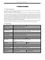
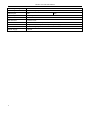
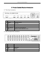
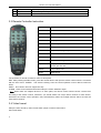
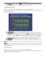
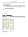
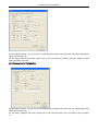
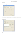
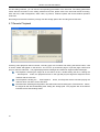
HD All-in-one DVR User manual HD All-in-one DVR User Manual Table of Contents 1. Product Introduction……………………………………………………………………………………….. 3 1.1 Product Summary ................................................................................................. 3 1.2 Parameters ............................................................................................................ 3 2. Product Outside Structure Introduction…………………………………………………………... 5 2.1 The Panel Instruction ............................................................................................ 5 2.2 The Connect Ports Instruction............................................................................... 5 2.3 Remote Controller Instruction ............................................................................... 6 2.4 Video format .......................................................................................................... 6 3. Operating Instruction………………………………………………………………………………………..8 3.1 Turn on/off DVR .................................................................................................... 8 3.2 Preview and turn on/off LCD panel ....................................................................... 8 3.3 Basic Menu Operation Instruction ......................................................................... 8 3.4 Main Menu Introduction ......................................................................................... 9 3.5 Video Playback...................................................................................................... 9 3.6 Manual Recording ............................................................................................... 11 3.7 PTZ Control ......................................................................................................... 11 3.8 Menu ................................................................................................................... 12 3.9 Log Information ................................................................................................... 18 3.10 Shutdown System ............................................................................................. 19 4. Client Operation Instruction……………………………………………………………………………20 4.1 The Main Page of the Video Monitoring .............................................................. 20 4.2 Bit Stream Selection ............................................................................................ 21 4.3 PTZ Control ......................................................................................................... 21 4.4 Advanced Setting Box ......................................................................................... 21 4.5 Talkback Control ................................................................................................. 22 4.6 Configuration ....................................................................................................... 22 4.7 Remote Playback ................................................................................................ 25 2 HD All-in-one DVR User Manual 1. Product Introduction 1.1 Product Summary This device is a digital monitoring and recording product specially designed for the security field, which integrate a revolvable 10.5 inch digital LCD panel. The device combines with the latest technologies in the IT field, such as standalone processor and standalone Linux operating system, video and audio compression/decompression, large capacity HDD record, TCP/IP network etc.. The code is embedded in the FLASH chip, which makes the system running more steadily. This device has both features of digital video and audio recording (DVR) and digital video and audio server (DVS). It can not only work locally and independently but also compose of a powerful security monitoring net with networking. With the use of professional network video surveillance platform (network) software, it can fully reflect its strong networking and remote monitoring capability. It can be used for the security protection in the fields of banking, telecommunications, electronic power, justice, traffic, residential, factory, warehouse, water conservancy facilities and other areas and departments. 1.2 Parameters Model 4 CHANNEL 8 CHANNEL Operation System Embedded Linux Operation System Operation Interface GUI, support mouse, pane, remote control operation Video Standard PAL, NTSC System Resources Multi-tasking operation, simultaneous multi-channel recording, simultaneous Video Compression H.264 Audio Compression ADPCM Recording Mode Manual, Timing, Alarm, Motion detection Search Mode By time, event, channel, log Backup Mode Network download, USB backup Video Input 4ch BNC video playback and simultaneous network operation. Video Output 8ch BNC Digital LCD panel:10.5 inch (Resolution:1024X768), CVBS, VGA Resolution: 1280X1024. Audio Input 4ch RCA Audio Output 1ch RCA Voice Talkback 1ch RCA Live Video Resolution PAL・720x576・D1 ・・NTSC・720x480・D1・ Playback Resolution PAL・352x288・CIF・・NTSC・352x240・CIF・ Image Control 1-6 level are selectable Motion Detection Each channel can set independent detection zones and multilevel sensitivity Video Display 1/4multiple display Recording Frame Rate PAL・25f/s(Adjustable) 3 8ch RCA 1/4/8multiple display NTSC・30f/s(Adjustable) HD All-in-one DVR User Manual Recording Storage Local Local Playback 1--8 channel playback at same time Alarm Input 4ch Alarm Output 1ch output PTZ Control RS485 HD Interface 1 SATA Ports Network Interface RJ45 Mobile Phone View Support 3G mobile phone with special operating system USB Interface 2 USB2.0 High-speed Port Power Supply 12V 3A 4 HDD, Network 4ch 10M/100M Adaptable Ethernet Connection HD All-in-one DVR User Manual 2. Product Outside Structure Introduction 2.1 The Panel Instruction 1 POWER Power key, use to turn on the device after soft shutdown. 2 SCREEN LCD panel on/off key. 3 REC Record key 4 MULIT Screen display mode switch key. 5 ESC Escape 6 MENU Menu key 7 Direct and Enter Up, down, left, right and Enter key 8 USB USB Port, connect to USB disk or mouse 9 Led Light POW: Power REC: Record 2.2 The Connect Ports Instruction 5 1 VIN1-VIN8 Channel 1~8 video input 2 VOUT Video output 3 AIN1-AIN8 Channel 1~8 audio input 4 AOUT Audio output 5 LINE Talkback 6 VGA VGA port 7 NET Network RJ45 port NET: Network HD All-in-one DVR User Manual 8 ALARM Alarm input/output, RS485 port 9 POWER DC 12V 3A power input 10 SWITCH Power on/off 2.3 Remote Controller Instruction Key name Function POWER Soft shutdown DEV Device number input 0~9 Number key MODE Display mode switch MENU Menu key ESC Escape and cancel Direct Up, down, left, right key OK OK or save PTZ Enter PTZ control mode Record Manual recording Playback Play, pause, fast forward, fast back, play as one frame, pre and next CLEAR Clear select area MUTE Mute on/off The operation of remote controller is same as front panel. DEV: After pressing the DEV button, press the number button and input the device number which is consistent with the host. Press・ENTER・ and save the setting. Then the control operation on this device comes into effect. SHIFT・This version does not support this key. CLEAR・Clear current selected area when setup the motion detection region. Note: When there are multiple devices in a same place, the remote control should choose a device first according to the device number. Therefore, you should define one unique device number for each device, otherwise, the remote control operation may simultaneously affect the multiple devices which are with the same device number. 2.4 Video format Setup the video format by video format switch jumper on device main board. PAL format state: 6 HD All-in-one DVR User Manual NTSC format state: 7 HD All-in-one DVR User Manual 3. Operating Instruction 3.1 Turn on/off DVR Please confirm the access AC voltage matches the requirements of the DVR and ensure that the middle earth terminal of the outlet connected to the ground well. After accessing to the power, the device will startup and the ・POWER・led will become red. Select the・SHUTDOWN・option in the main menu to soft-off, and pressing the ・POWER・again will turn on the device. 3.2 Preview and turn on/off LCD panel 3.2.1 Preview The device will enter the preview screen when it starts normally. The date, time and channel name of the system will be indicated on the preview screen. Pressing the code corresponding button on the panel or clicking the left mouse button can start single-screen preview. Pressing the・MULTI・button on the panel again or clicking the left mouse button can return to the state of multi-screen preview. 3.2.2 Turn on/off LCD panel After device starts normally, Pressing・SCREEN・key on the front panel will turn on/off the LCD panel. 3.3 Basic Menu Operation Instruction 3.3.1 Enter the Menu Mode Press the ・MENU・ button to enter the main menu interface of the device. Press the・Play・shortcut to enter the playback operation interface. Press the ・REC・shortcut to enter the manual recording operation interface. Press・PTZ・shortcut to enter the PTZ control interface. 3.3.2 Menu Component Instruction The component units of the menu mainly include the following kinds: (1) Checkbox: Provide two kinds of state options. “√” means valid, while “□” means invalid. Use the ・ENTER・ button or ・↑・,・↓・button or click the left mouse button to choose. For example, the “Channel” and “Type” select box on the page of the file search menu. (2) Select box: Provide more than 2 options, but only one option can be chosen. Use・↑・, ・↓・ button or click left mouse button to turn up and click right mouse button to turn down. For example, the “Storage Device” select box on the page of the file search menu. (3) List box: Display the search result information in the list. You can choose one item and carry out corresponding operation. 8 HD All-in-one DVR User Manual For example, press the ・ENTER・button on the list of playback search result or click left mouse button to play this file information. Click right mouse button can select/cancel this video file in order to backup this video file. (4) Edit Box: Input target name through edit box. For example, on the page of the system configuration menu, numbers, English letters and Chinese etc. can be input into the “Device Name” edit box. a) Single-clicking left mouse button on “ ” can switch input type, including number, upper-alpha and lower-alpha, punctuation, Chinese input method. There will be current input method indicated following the activity box. b) After moving the location of the edit box place cursor by ・←・ ・→・ , button on the panel or by mouse, pressing the ・ENTER・ button or single-clicking left mouse button, the input keyboard will appear. Then select the target characters by direction buttons or single-clicking the left mouse button. c) Delete the character before the cursor by the・MENU・button or single-clicking the right mouse button. d) After the input is complete, exit the edit status by pressing the ・ESC・ button or clicking the right mouse button. (5) Button: Used for the implementation of a specific function or entering the second-level set menu. Press ・ENTER・ or click left mouse button to confirm access. 3.3.3 Exit the Menu Mode Pressing・ESC・ or clicking right mouse button can exit the menu mode and switch to the multi-screen preview mode. Pressing ・ESC・ or single-clicking right mouse button will return to the previous menu. 3.4 Main Menu Introduction Press ・MENU・ or click right mouse button to popup the main menu. The main menu consists of the following three components: Preview Mode: Choose the corresponding preview screen mode in the menu bar. Shortcut Menu: There are video playback, manual recording and PTZ control shortcut menu in the menu bar, from which you can enter the corresponding menu page directly. Main Menu Bar: After entering the menu bar, there will be the menu page of management tools, system setting, log search, shut down system. 3.5 Video Playback Single-click the “Video Playback” in the main menu bar to enter the file search operation interface. 3.5.1 File Search Select Channel: Select the target channel to be searched and click the checkbox to select. Recording Type ・ Select the recording type to be searched. “√” means selected; “□”means unselected. Time Bucket Setup: Input the start and stop times of the video to be searched in the edit box. Storage Device: Select the target backup storage device in the select box. 9 HD All-in-one DVR User Manual File Search Button: When the settings of the above search conditions are complete, clicking this button, the system will start searching the corresponding video information and entering the search result interface. Note: If the quantity of the video files which meet the search conditions is bigger than 4000, the system will only indicate the latest 4000 video files. If you want to search for the updated files, please modify the search conditions. Playback by Time: Start playing back the video according to the set start and stop times・regardless of recording type・ For the playback tool control, please refer to 3.5.3. Backup: Backup all the videos which are within the set start and stop times to the designated storage device. 3.5.2 Search Result When the setting of the search conditions is complete, single-clicking the・File Search・button will enter the search result interface. Video File Playback: In the list box of search result, positioning the target file by the up and down button or moving mouse, click ・ENTER・or left mouse button to play this file. Page Turning: The searched video files are page displayed. Single-click ・Page Up・, ・Page Down・ button or input the target page number in the page number box and then press “Jump” button or scroll the middle button of the mouse to turn the page. Backup: In the list of search result, positioning the target file by the up and down button or by moving mouse and then use the・FN・ button or right mouse button to select the file. In the storage device select box, selecting the target storage device, then clicking the ・Backup・ button will backup the selected video file to the target storage device. Cancel Button: Return to the previous menu. 3.5.3 Playback Tool Control Choosing file playback or playback by time will enter the video playback interface. Playback Toolbar: Playback toolbar will appear at the bottom of the playback interface. Click right mouse button can hide/display the toolbar. When multi-screen playing back simultaneously, clicking right mouse button to hide the toolbar, then the corresponding channel video can be enlarged or diminished by single-click left mouse button. Stop playing: Click , the system will stop playing and return to the playback interface. Pause/Play: Click to pause playback; click to go on playback. Single-frame Playback: Under the pause mode, click can start single-frame play; click once will play one frame forwards. Slow Forward: Click to start slow forward; click it again to set the slow forward multiple. Fast Forward: Click to start fast forward; click it again to set the fast forward multiple. Last Section/Next Section: Click or , each click last section or next section, the video will forward or backward 10%. Turn off/on Sound: Click or to turn off or turn on the sound of the playback file. Playback Status Information: The right side of the toolbar will respectively show the play speed, play progress, playing time and total time of the video file. 10 HD All-in-one DVR User Manual Exit Playing: Clicking ・ESC・ or can exit the playback screen at any time; when finishing playing all the video files, it will return to the playback screen automatically. 3.6 Manual Recording Single-click ・Manual Recording・in the main menu bar to enter the setting interface. Press the ・REC・ button or click ・Manual Recording・ in the main menu bar by mouse can enter the manual recording setting interface. Manual recording operation interface consists of the following parts: Channel Number: Correspond with the video channel of the device. Channel State: Indicates the recording status of the corresponding channel. When the status led is green“ ”, it means unopened video; the status led is red " ", it means open video; when there is a coil around the status led“ ”, “ ” means the corresponding channel opening the network video transmission. When the system is under the status of recording (regardless of recording type), “ ” will appear at the bottom left corner of the channel preview screen which means the system is recording. Start All/Stop All: Single-click this button to stop or start the video setting of all the channels. Back Button: Single-click the back button to exit manual recording interface and return back to the main menu bar. Note: If the recording is enabled manually, you can only stop it manually, otherwise, the recording will continue all the time. Attention: Manual recording operation requires that the user has the “recording” operation authority. Before the operation, please confirm with the administrator that the hard disk has been installed in the DVR and it has been formatted correctly. 3.7 PTZ Control Single-click ・PTZ Control・in the main menu bar to enter the setting interface. The main operations of the PTZ control are direction control, horizontal scanning, ZOOM control, focal adjustment, aperture adjustment and PTZ speed. 11 HD All-in-one DVR User Manual After switching the page, the preset point can be invoked; start up/stop automatic cruise; wiper control; light control; auxiliary device control. Note: The invoked preset points must have be set up well. For the setting methods of the cruise path, please refer to 3.8.2.8 PTZ setting. If the cruise path number is less than 2 digits, you need to add 0 before the corresponding cruise path number to make up for 2 digits. 3.8 Menu Click ・MENU・ in the main menu bar to enter the main menu page. The first-level menu includes management tools, system setting, log search, system shutdown. 3.8.1 Management Tools Management tools include HDD management, user management, default configuration, alarm clear, software update, date and time, system information. 3.8.1.1 HDD Management SATA: Displays the current system HDD information; “√” means HDD detected successfully; “X” means no hard disk detected. HDD Format: In the HDD select box, selecting the target disk can view the information of the corresponding disk; clicking the ・Format・ button will show the confirmation page; clicking the ・OK・button will start formatting the HDD; after the HDD formatting is complete, the hard disk can be used normally. Note: All the videos must be stopped before the HDD formatting. 3.8.1.2 User Management Create, add and delete user and modify the user information. (No one has the right to set other user authority except the admin.) Create New User Enter the“User Management”operation interface, click ・ADD・ button and enter the add user interface. Note: For the input methods, please refer to 3.3.2・4・edit box. 1) Input New User Name Input a new user name in the user name edit box・such as: user・. Note: For the input methods, please refer to 3.3.2・4・edit box. 2) Setup Password of New User Choose the “Setup Password” button in the “Add User” interface and input the new password on the password setup page. The password is within 6 digits. 3) Setup the Authority of the New User Setup the operation authority for the new user on the "Add User" interface, and then make selection in the checkbox with corresponding functions. “√” means that the user can use this authority; “□” means that the user cannot use this authority. 4) Save the Setup Information of the New User Single-clicking the ・OK・ button, the setup information of the new user will be saved while clicking the ・Cancel・ button, the setup information of the new user will not be saved. Modify User Enter the “User Management” operation interface, single-click the right mouse button or press ・ENTER・ on the panel in the user list to select the target user, then single-click the ・Modify・ 12 HD All-in-one DVR User Manual button, enter the “Modify User” page to modify the user information. Note: Admin administrator can modify the authority of other users. Delete User Enter the “ User Management”operation interface, single-click the right mouse button or press ・ENTER・ on the panel in the user list to select the target user, then click ・Delete・ to delete the user. 3.8.1.3 Restore Default Restore the system configuration parameters to factory configuration. The system will restart after the restore is complete. 3.8.1.4 Alarm Clear Clear all the alarm information manually. When the alarm is cleared successfully, the system will indicate “Alarm has been successfully cleared”. Confirm and return to the page of management tools. 3.8.1.5 Software Update Choose the “Software Update” on the management tools interface to enter the operation interface. Select the target to be updated in the update select box, then select the update mode in the update method select box: FTP or USB. USB Update: Copy the file to be updated to the USB root catalogue, insert USB and click ・OK・ to update the system. FTP Update・Put the file to be updated to the FTP server root catalogue and set the IP address of the server as the designated address, then press ・OK・ to update the system. After the update is complete, the system will restart automatically. Note: The update name of the main board should be: mainboard.bin; the update name of the panel should be: panel. bin. When the system is being updated, do not disconnect the power so as to avoid device failure. 3.8.1.6 Time Setting Enter the date and time page, input the exact date and time in the "Date”, “Time”edit box, then confirm and save or cancel and exit. 3.8.1.7 Version Information Check the relevant information of the device name, item number and the version number. 3.8.2 System Setup Choose the “System Setup” to enter the sub-menu interface on the main menu interface, including system parameter, code parameter, image parameter, and alarm input, alarm output, Schedule, motion detection, PTZ configuration and network. 3.8.2.1 System Setup Choose the "Setup" and enter its setting interface on the system setting interface. Device Number: When using the remote control to operate the device, the communications with the remote control is realized y the device number. To realize the remote control operation, the remote control must correspond to the device number. For the settings of the remote control device number, please refer to 2.3 remote control instruction. Device Name: Device name is normally defined as the area name of the monitoring point. When remote access, you can find the monitoring point to be visited intuitively. The default device name is “H.264 NDVR”. For the edit method, please refer to 3.3.2・4・edit box. Device Overwrite: When all the hard disks inside the device are full, choose "Yes", the system will overwrite the earliest video information to achieve the purpose of cycle recording. 13 HD All-in-one DVR User Manual Keypad Lock Time: There is no operation within the keypad lock time. The system will cancel the current user automatically. To operate, you need to relogin the system. Switch Time: Switch time means the cycle time indicated on the single-channel preview. VGA Resolution: Adjust the VGA video output resolution. There are 800*600/60Hz, 1024*768/60Hz and 1280*1024/60Hz options. Video Format: The device supports PAL and NTSC video output. The default video output is “NTSC”. Menu Transparency: When the user enters the menu operation interface, you can realize the transparency between the screen preview and menu by adjusting the level of the menu transparency. Language: 12 kinds of commonly used languages including Simplified Chinese, English, etc.. According to the user's needs, any menu language type can be setup (language pack is needed) State Display: Setup if the information icons of the recording mode, state and motion detection will be indicated on the screen preview. When the mark is changed into “√”, it means state displayed; when the sign is changed into “□”, it means state not displayed. The explanations for the lower left corner icons on the channel screen preview. “ ” The system is recording(regardless of recording type). “ ” Timing recording state. “ ” Manual recording state. “ ” Motion detection state. Login Verification: If you choose “Enable”, you will need to input the password to login when cancelling the menu users, restarting and shutting down the system; if you choose “Disable”, you will not need to login. When the page setting is complete, single-clicking the ・OK・ button, the setting information will be saved and it exits; single-clicking the ・Cancel・ button, it will exit without saving the setting information. 3.8.2.2 Record Choose “Record” on the system setting interface to enter its setting interface. Select Channel: Select the target channel to be set, click select box to select. Bit Stream: Select the bit stream to be set. There are "Main Bit Stream" and "sub-bit stream”. Bit Stream Type: Choose the video bit stream type. “Video Stream" means that when the system is recording, it only encodes the video; “Compound Stream" means that when the system is recording, it encodes both the video and audio. Bit Rate Type: User can set up "Fixed Bit Rate" and "Variable Bit Rate". "Fixed Bit Rate" means that the system will encode the image according to the bit rate and video frame rate which are set by the user; "Variable Bit Rate" means the system encodes according to the image quality and video frame rate which are set by the user, but the bit rate is adjusted automatically by the system according to the video scene. Bit Rate: The user selects the bit rate of the code as needed. The higher bit rate, the better image effect, but occupies the more hard disk space. Video Frame Rate: The user selects the video frame rate to be encoded. The higher frame rate, the better image fluency, but also occupies the more hard disk space. Copy to: Selecting the target channel in the select box on the right side of the ・Copy to・ button, single-clicking the ・Copy to・ button, the setting information of the current channel will be applied to other target video channels by the system. When the page setting is complete, single-clicking the ・OK・ button, the setting information will be saved and it exits; single-clicking the ・Cancel・ button, it will exit without saving the setting information. 14 HD All-in-one DVR User Manual 3.8.2.3 Video Choose “Video” on the system setting interface to enter its setting interface. Select Channel: Select the target channel to be set and click the select box to select. Channel Name: In the edit box, the user is free to edit the channel name. For the edit method, please refer to 3.3.2.・4・edit box. Show Name: “√” means show; “□” means not show. Click ・Position・ button and enter the setting interface. Setting can be realized by the direction buttons on the panel or by mouse dragging the red channel. When the setting is complete, press the ・ENTER・ button or click right mouse button to save and exit. Clicking the・ESC・ button will exit without saving. Show Time: “√” means show; “□” means not show. Click “position” button and enter the setting interface. Setting can be realized by the direction buttons on the panel or by mouse dragging the red channel. When the setting is complete, press the ・ENTER・ button or click right mouse button to save and exit. Clicking the ・ESC・ button will exit without saving.. Image Parameter: The brightness, contrast, hue and saturation of the channel image can be configured. Use the ・↑・・↓・button on the panel or mouse dragging the scroll bar to adjust. Envelop: Set the "Envelop" option mark to be "√" to activate the “Zone” button and enter the envelop zone setting interface. Set Envelop Zone: On the envelop zone setting interface, a small yellow box will appear in the middle of the area namely envelop setting box. Zone Creation: move the yellow box to the start position of the setting area by the direction buttons of the panel; Press ・FN・ button(switching between yellow box and red box) to change it into red box(red box is the effective cover area box), then adjust the zone size by direction buttons. The minimum size can be set up is a small box while maximum 4 envelop zones can be set up. Single-click or long press left mouse button and move the mouse can choose zone. After the setting is complete, press the ・ENTER・ or click the middle mouse button to exit and save. Clicking the ・ESC・button will exit without saving. Local Clear: Move the yellow box to the start position(upleft) of the zone to be cleared. Press ・FN・, it will change into a small black box(local clear box), local is cleared. After the clear is complete, press ・ENTER・ button to save and exit. If press ・ESC・, the clear operation will be invalid. Clicking the left mouse button in the red box or long pressing the left mouse button and moving mouse can clear the zone. Click the middle mouse button to exit and save. Clear All: Press ・MENU・ to clear all the envelop zones of the channel. Reset Color: The setting image parameter can be restored to the system default value(only the restore of image parameters) by clicking this button. Copy to: Selecting the target channel in the select box on the right side of the ・Copy to・ button, single-clicking the ・Copy to・ button, the setting information of the current channel will be applied to other target video channels by the system. Note: The channel name cannot be copied. When the page setting is complete, single-clicking the ・OK・ button, the setting information will be saved and it exits; single-clicking the ・Cancel・ button, it will exit without saving the setting information. 3.8.2.4 Alarm Input Choose the “Alarm Input” on the system setting interface to enter its setting interface. Input Channel: Select the target channel to be set and click select box to select. Alarm Type: High level and low level can be set up. Please choose the appropriate level for the alarm connected to the alarm input channel. Detection: You can set up if the system detect alarm input signal. Choose “Yes”, the following setting 15 HD All-in-one DVR User Manual functions will take effect; choose “No”, nothing is conducted. PTZ Link・Single-click ・PTZ・ button to enter the PTZ link interface. Choose the channel number and conduct related settings of PTZ link: preset point, cruise, track. For the setting methods, please refer to 3.8.2.8. Mail Alarm: If mail alarm is needed. “√” means display; “□” means not display. Time Delay: When the alarm input is complete, set up the delay time needed for dealing with each point. Buzzer: If buzzer alarm is needed. “√” means enable; “□” means invalid. Trigger Recording: You need to trigger the designated recording channel number when you are setting up the alarm input. Alarm Output: You need to trigger the designated alarm output channel number when you are setting up the alarm input. Input Detection: You can choose "Disable" and "Enable". Copy to: Selecting the target channel in the select box on the right side of the ・Copy to・ button, single-clicking the ・Copy to・ button, the setting information of the current channel will be applied to other target video channels by the system. When the page setting is complete, single-clicking the ・OK・ button, the setting information will be saved and it exits; single-clicking the ・Cancel・ button, it will exit without saving the setting information. 3.8.2.5 Alarm Output Choose the “Alarm Output” on the system setting interface to enter its setting interface. Output Channel: Select the target channel to be set up and click the select box to select. Alarm Type: “Normal Close Type” and “Normal Open Type”. Choose the corresponding type. Copy・Selecting the target channel in the select box on the right side of the ・Copy to・ button, single-clicking the ・Copy to・ button, the setting information of the current channel will be applied to other target video channels by the system. Alarm Mail: Input E-mail on the right of the alarm mail. When local alarm occurs, it will send a prompt message to the corresponding E-mail. When the page setting is complete, single-clicking the ・OK・ button, the setting information will be saved and it exits; single-clicking the ・Cancel・ button, it will exit without saving the setting information. 3.8.2.6 Schedule Choose “Schedule” on the system setting interface to enter its setting interface. Select Channel: Select the target channel to be set up and click the select box to select. Week: Select the date to be set up. You can set up respectively; “All” means all the dates. Recording Type and Time Bucket: Within the four time buckets, each time bucket can set up different recording types: timing recording(red), motion detection recording(green), alarm recording(yellow). "√" means enable; "□" means invalid. There is time bucket status indicated at the bottom. It is a whole plan of 0 to 24 hour. Copy to: Selecting the target channel in the select box on the right side of the ・Copy to・ button, single-clicking the ・Copy to・ button, the setting information of the current channel will be applied to other target video channels by the system. When the page setting is complete, single-clicking the ・OK・ button, the setting information will be saved and it exits; single-clicking the ・Cancel・ button, it will exit without saving the setting information. 3.8.2.7 Motion Detection Choose the “MTD” on the system setting interface to enter its setting interface. Channel: Select the target channel to be set up and click the select box to select. 16 HD All-in-one DVR User Manual Type: Motion detection, video loss and video block can be chosen. Recording Channel: When the detection occurs, the designated recording channel number needs to be triggered. Alarm Output: When the detection occurs, the designated alarm output channel number needs to be triggered. Buzzer: If buzzer alarm is needed. “√” means enable; “□” means invalid. Sensitivity: Choose triggering motion detection sensitivity. “No Detection” means the above setting parameters are invalid. Area: Setting up the motion detection area. For the setting methods, please refer to 3.8.2.3 envelop zone setting. Delay: When the signal detection is complete, set up the delay time needed for dealing with each point. Mail alarm・Mail Alarm: If mail alarm is needed. “√” means display; “□” means not display. Copy to: Selecting the target channel in the select box on the right side of the ・Copy to・ button, single-clicking the ・Copy to・ button, the setting information of the current channel will be applied to other target video channels by the system. When the page setting is complete, single-clicking the ・OK・ button, the setting information will be saved and it exits; single-clicking the ・Cancel・ button, it will exit without saving the setting information. 3.8.2.8 PTZ Setup Choose the “PTZ Configuration” to enter its setting interface. Select Channel: Select the target channel to be set up and click the select box to select. Rate: Select the rate which matches the connected PTZ. Data Bit: Select the data bit which matches the connected PTZ. Stop Bit: Select the stop bit which matches the connected PTZ. Check: Select the check value which matches the connected PTZ. Flow Control: The selected items must match the PTZ flow control setting. Protocol Type: The selected items must match the PTZ protocol. Decoder Address: Input designated decoder address. Preset Point Setting: Preset point is to preset and memorize the position, focus, aperture and zoom of the camera and use a number to identify these settings at the same time. 1) Add Preset Point: Input a preset point in the preset point edit box, ranging from 1-128, then adjust the camera to the target position. When the adjustment is complete, pressing “set”, the preset point will be saved. 2) Delete Preset Point: Input a preset point to be deleted in the preset point edit box, click ・Delete・. Cruise Path Number Setting: Cruise path is a path on which a camera running at a certain speed. It passes various cruise points with numbers. Each cruise point includes stay preset points and retention time. Thus, the settings of cruise path include the parameters setting for the cruise point, preset point, retention time and cruise speed etc. Corresponding information can be set up on the “Setting” interface. At present, one device supports the setting of 16 cruise path numbers. Track Setting: Track is a line which is used to record the predefined irregular movement of the camera. Entering “Setting” can set track. Copy to: Selecting the target channel in the select box on the right side of the ・Copy to・ button, single-clicking the ・Copy to・ button, the setting information of the current channel will be applied to other target video channels by the system. When the page setting is complete, single-clicking the ・OK・ button, the setting information will be saved and 17 HD All-in-one DVR User Manual it exits; single-clicking the ・Cancel・ button, it will exit without saving the setting information. 3.8.2.9 Network Setup Choose “Network” on the system setting interface to enter its setting interface. There are "Ethernet Configuration, PPPOE Configuration, DDNS configuration". 1) Ethernet Configuration: Choose “Ethernet Configuration” on the network configuration interface to enter its setting interface. Physical Address: Indicate the physical address number of the device. Port Number・The default port number is 6650. IP address・The IP address must be exclusive, which can not be conflict with any other host or workstation during the same network segment. Subnet Mask: It is used to divide subnet segment. Default Gateway: Realizes the communications between different network segments. Gateway address needs to be set. DNS Address: When the device is connected to the network using PPPoE protocol, it will gain a dynamic IP address. DHCP: Choose whether to enable DHCP to obtain IP automatically. Http Port: The port number which the IE browser visit. The default port is 80. When the page setting is complete, single-clicking the ・OK・ button, the setting information will be saved and it exits; single-clicking the ・Cancel・ button, it will exit without saving the setting information. 2) PPPOE Configuration: Choose “PPPOE Configuration" on the network configuration interface to enter its setting interface. Enable: "√" means enable PPPOE protocol and dial-up internet access; " □ " means do not enable this function. User Name and Password: Input the user name and password provided by ISP in the edit box. For the edit methods, please refer to 3.3.2・4・edit box. When the page setting is complete, single-clicking the ・OK・ button, the setting information will be saved and it exits; single-clicking the ・Cancel・ button, it will exit without saving the setting information. 3) DDNS Configuration: Choose “"DDNS Configuration" on the network configuration interface to enter its setting interface. Enable: "√" means enabling DDNS dynamic domain name service; " □ " means do not enable this function. Servicer: Choose the corresponding servicer. User Name, Password and Domain Name: Input the user name, password and domain name applied from the internet. For the edit methods, please refer to 3.3.2・4・edit box. When the page setting is complete, single-clicking the ・OK・ button, the setting information will be saved and it exits; single-clicking the ・Cancel・ button, it will exit without saving the setting information. 3.9 Log Information Choose “Log Search” on the main menu page to enter its operation interface. Type: Select the target log type in the select box. Time Setting: Input the time bucket of viewing in the edit box. Single-click ・Log Search・, the corresponding log information will appear in the log list at the bottom. You can turn page by inputting target page number in the page number box or by single-clicking ・OK・ button. 18 HD All-in-one DVR User Manual 3.10 Shutdown System Choose “Shutdown” on the main menu interface to enter its operating system. Choose the corresponding operation contents in the select box. Log out: It is used to cancel the current user. After log out, if you want to continue to use the device, you need to login the system again. Restart: Restart the device. After confirmation, the device will be restarted. Shutdown: Shutdown the device. After confirmation, the device will be shut down. 19 HD All-in-one DVR User Manual 4. Client Operation Instruction When you use the client on PC, please conduct the following settings: IE Setting: If it is used for the first time, the activex cannot be loaded, the IE must be set as follows: ToolsInternet OptionsSecurity-InternetCustom LevelEnable all the activexs and plugins. Click “OK” finally. Login: Open IE and input the IP address of the host network setting in the address bar (the factory IP address is: http://192.168.1.114), then enter the login page. Input the user name and login password. If the user name and password match with the ones of the host-side, and the input user information is correct, then the login will be successful. 4.1 The Main Page of the Video Monitoring After login, the main page of the monitoring consists of preview window, PTZ control, preview mode, bit stream selection, channel open, talkback open, configuration and playback. 20 HD All-in-one DVR User Manual Open Preview: Click left mouse button to select the target channel in the preview window (red channel box means selected). Double-clicking the channel number by mouse in the channel open box can open or close the video image of the corresponding preview window. open, means means close. Preview Mode: Click or double-click the preview window screen by mouse in the switch box under preview mode to switch between single-screen or multi-screen preview mode. 4.2 Bit Stream Selection This device supports double bit stream. Choose the bit stream type of video preview in the bit stream select box. 4.3 PTZ Control A. PTZ direction control button. You can control the PTZ operation direction by the up, down, left, right button. B. The aperture button. You can control the PTZ aperture by enlarge and diminish button. C. Focus button. You can control the PTZ focus by the farther adjustment or nearer adjustment. D. Zoom button. You can control the PTZ position by zoom out and zoom in. 4.4 Advanced Setting Box When the preview window opens the video preview, this function will be activated. Click right mouse button to open the advanced setting box. Turn on/off Audio: Turn on or turn off the audio of the previewing by this button channel. Screenshot: Capture the current video image and save it as image format. For the settings of directory storage, please refer to the figure 1-5-5 video screenshot directory storage. Recording/Turn off Recording: Turn on/off the remote recording of the video of this channel and save this recording. For the settings of directory storage, please refer to 1.5.5 video screenshot directory storage. 21 HD All-in-one DVR User Manual PTZ Setting: Conduct the settings of PTZ preset point, cruise path, track. For the setting methods, please refer to 3.8.2.8 host-side PTZ setting. OSD Setting: Set up the channel of OSD layer, time display position. Mouse drags the position and saves after confirmation. Motion Detection: Setting the motion detection area: First, “√” displays motion detection area. Choosing “Add Area”, pressing left mouse button and dragging on the screen, there will be a latticed area with white lines namely motion detection area. Choosing “Clear Area”, pressing left mouse button on the screen of the latticed area with white lines and mouse dragging the latticed area, the white lines will disappear. The motion detection area is cancelled. Choose the corresponding parameter in the sensitivity and output delay box. Screen Adjustment: Set the brightness, contrast, hue, saturation. Click left mouse button or adjust by dragging. It will save automatically when exit. 4.5 Talkback Control Click to open voice and initiate the talkback actively. 4.6 Configuration 4.6.1 Sever Parameter Configuration On this setting interface, you can set the corresponding parameters of the host-side. The setting parameters match with the host-side. For the setting methods and notes, please refer to the host-side system configuration, system information and network operation instruction. 4.6.2 Channel Parameter Configuration 22 HD All-in-one DVR User Manual On this setting interface, you can set the corresponding parameters of the host-side. The setting parameters match with the host-side. For the setting methods and notes, please refer to the host-side image setting, recording setting and PTZ setting operation instruction. 4.6.3 Alarm parameter Configuration On this setting interface, you can set the corresponding parameters of the host-side. The setting parameters match with the host-side. For the setting methods and notes, please refer to the host-side alarm input and alarm output operation 23 HD All-in-one DVR User Manual instruction. 4.6.4 User Configuration Information For the user information of the setting device the setting parameters match with the host-side. For the setting methods and notes, please refer to the host-side user management operation instruction. 4.6.5 Others 24 HD All-in-one DVR User Manual On this setting interface, you can set the corresponding parameters of the host-side. The setting parameters match with the host-side. For the setting methods and notes, please refer to the host-side manual recording, date and time, HDD management, alarm clear, log search, software update and restore default operation instruction. Recording and screenshot directory storage: Set the storage path of the recording and screenshot. 4.7 Remote Playback Choosing video playback channel number, recording type, time condition and clicking the search button, a list of search results will appear on the left box. You can turn up and down page or input the page number and jump to view the video files・one page displays 20 file messages and maximum supports 4000 messages・. File Playback: Selecting the target file in the search list box, double-clicking the file or clicking the ・File Playback・ button, the playback window on the right will play the target file. Playback control matches with the host-side. Time Playback: Clicking the ・Time Playback・ button, the Playback window will start playing the video file which has been set the start time. File Download: Selecting the target file in the search list box and clicking the・File Download・ button, the target file will start downloading after setting the storage path. The progress bar at the bottom indicates the file downloading status. 25