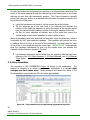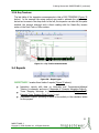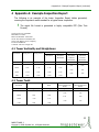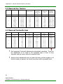
1
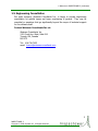
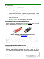
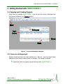
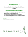
INSPECTOWER 3
Communication Tower Inspection Software
Version 1.0.0
Getting Started with INSPECTOWER 3
A Computer Program for the Specialized Inspection and Mapping of Guyed
Lattice Towers and Self-Supporting Lattice Towers,
with Graphical Display of 2D Tower Elevation Profiles and Plans,
with reference to US Standards TIA-222-G and TIA/EIA-222-F, Canadian
Standard CAN/CSA-S37-01, and Australian Standard AU 3995:1994.
INSPECTOWER 3
Copyright © 2009 Guymast Inc. All Rights Reserved.
Limit of Liability
This manual and the program it describes have been prepared with due care. The
program has been tested and we are satisfied that it performs in accordance with
the description contained in this manual.
The user should know, however, that because of possible variances, neither
Guymast Inc. nor its staff can assume responsibility for accuracy of results or for
damages resulting from the use of this manual or the program described herein.
Copyright
INSPECTOWER and GUYMASTER are proprietary to Guymast Inc., which reserves all
rights with respect to them. This publication may not be reproduced in whole or in
part without prior written permission from Guymast Inc.
INSPECTOWER,
GUYMASTER, and this manual are Copyright © 2009 Guymast Inc. All Rights
Reserved.
GUYMASTER, GUYMAST-G, GUYMAST, MAST, MASTLOD, POLEMAST, POLELOD,
DRAWFORCE,
DRAWMAST,
DRAWMAST3D,
DISHFORCE,
OUTRIG,
and
INSPECTOWER are trademarks of Guymast Inc.
Safe-Net Inc.
Sentinel Protection software and Sentinel and Sentinel Ultra-Pro hardware
encryption keys are used under license from Safe-Net Inc.
Microsoft Corp.
Microsoft Office, Microsoft Excel, Microsoft Word, Microsoft Outlook, Microsoft
Windowsxp, and Microsoft Windows Vista are trademarks of Microsoft Corp.
FreeImage
This software uses the FreeImage open source image library.
See
freeimage.sourceforge.net for details. FreeImage is used under the FreeImage
Public License, version 1.0.
INSPECTOWER 3
Copyright © 2009 Guymast Inc. All Rights Reserved.
Table of Contents
Page
Table of Contents
i
Table of Figures
iii
1
1
Welcome to INSPECTOWER 3
1.1 What’s New? ............................................................................................................................ 1
1.2 Licenses and Support ............................................................................................................... 1
1.2.1 Standalone License ................................................................................................................... 1
1.2.2 Network License ....................................................................................................................... 1
1.2.3 Support and Update Contracts ................................................................................................... 2
1.3 Information, Feedback, and Suggestions ................................................................................ 2
1.4 Training .................................................................................................................................... 2
1.5 Engineering Consultation ......................................................................................................... 3
2
Installation
5
2.1 License Protection Hardware Key and Driver .......................................................................... 5
2.2 Maintenance, Updates, and Upgrades ...................................................................................... 5
3
Getting Started with INSPECTOWER 3
7
3.1 Opening and Creating Projects ................................................................................................ 7
3.1.1 Open an existing project............................................................................................................ 7
3.1.2 Change the current Workspace .................................................................................................. 8
3.1.3 Create a new project ................................................................................................................. 8
3.2 Mapping a tower ...................................................................................................................... 9
3.2.1 Mast Geometry ....................................................................................................................... 10
3.2.2 Adding pictures for more detail ................................................................................................ 11
3.2.3 Mast Materials ........................................................................................................................ 12
3.2.4 Material Types ........................................................................................................................ 12
3.2.5 Another use for pictures .......................................................................................................... 13
3.2.6 Material Properties .................................................................................................................. 14
3.2.7 Guy Geometry ........................................................................................................................ 15
3.2.8 Congratulations! ..................................................................................................................... 15
3.3 Inspection .............................................................................................................................. 16
3.3.1 Transit Location ...................................................................................................................... 16
3.3.2 Transit Readings ..................................................................................................................... 17
3.3.3 Guy Assemblies ....................................................................................................................... 20
3.3.4 Guy Tensions .......................................................................................................................... 21
3.4 Reports ................................................................................................................................... 21
i
INSPECTOWER 3
Copyright © 2009 Guymast Inc. All Rights Reserved.
Table of Contents (continued)
Page
4
Appendix A: Example Inspection Report
23
4.1 Tower Verticality and Straightness .........................................................................................23
4.2 Tower Twist.............................................................................................................................23
4.3 Measured Guy Tensions ..........................................................................................................24
4.4 Measured Turnbuckle Gaps .....................................................................................................24
5
Appendix B: Example Tower Drawing (Draw Tower)
ii
INSPECTOWER 3
Copyright © 2009 Guymast Inc. All Rights Reserved.
25
Table of Figures
Figure
Figure
Figure
Figure
Figure
Figure
Figure
Figure
Figure
Figure
Figure
Figure
Figure
Figure
Figure
Figure
Figure
Figure
Figure
Figure
Figure
Page
1 — SafeNet Inc.'s Sentinel UltraPro and Sentinel USB Keys ..............................................................5
2 — Project and Workspace Manager ...............................................................................................7
3 — Working with Workspaces ........................................................................................................8
4 — Starting a new project — step 1................................................................................................8
5 — Starting a new project — step 2 — Project Properties — Main tab ...............................................9
6 — Starting a new project — step 3 — Project Properties — Project ID tab .......................................9
7 — Describing Mast Geometry ...................................................................................................... 10
8 — Including pictures for greater clarity and more complete mapping ............................................ 11
9 — Specifying the material used for various mast elements in the tower ......................................... 12
10 — Material Types used for mast elements and appurtenances .................................................... 13
11 —Store an image of a useful table found online ......................................................................... 13
12 — Some Material Properties ...................................................................................................... 14
13 — Guy Geometry information to be entered ............................................................................... 15
14 — Transit Location measurements ............................................................................................ 16
15 — Transit Readings .................................................................................................................. 17
16 — Anchor Location by Transit ................................................................................................... 18
17 — Mast Alignment and Deflections by Transit ............................................................................ 19
18 — Guy Assemblies as recorded during mapping and inspection ................................................... 20
19 — Guy Tension measurements .................................................................................................. 21
20 — Report types ........................................................................................................................ 21
21 — Example Draw Tower tower drawing ..................................................................................... 25
iii
INSPECTOWER 3
Copyright © 2009 Guymast Inc. All Rights Reserved.
1 Welcome to INSPECTOWER 3
INSPECTOWER 3 is a powerful tool for the calculation of values associated with the
inspection of latticed towers, both guyed and self-supporting.
1.1 What’s New?
INSPECTOWER has undergone many significant changes since its last version. With
INSPECTOWER 3 you can map towers, which can then be viewed in profile and plan
drawings. This data can be imported into GUYMASTER, Guymast Inc.’s powerful
tower analysis software for use in engineering with little or no additional data
needed, saving time and money. INSPECTOWER 3 is the best software available for
tower inspection.
1.2 Licenses and Support
1.2.1 Standalone License
A standalone license permits use of a single copy of INSPECTOWER 3 on a single
computer with a single hardware key. Multiple copies of the software may be
installed anywhere desired, but only one can be in use at a given time, as the
software will only run if the key is installed on that computer. Multiple standalone
licenses may be used, each with their own key.
1.2.2 Network License
A network license permits use of one or more copies of INSPECTOWER 3 anywhere
on a network at any given time. For example, with a network license for 5 copies,
up to 5 users can be logged on at any given moment with a single hardware key,
permitting access to those 5 licenses from the network server.
!
It should be kept in mind that a network license allows access to the software
more conveniently for more of the company’s users over the working day,
from a centrally administrated position; however, if you want to take your
computer with you, you will still need a 1.2.1 Standalone License and its
hardware key.
1
INSPECTOWER 3
Copyright © 2009 Guymast Inc. All Rights Reserved.
1 Welcome to INSPECTOWER 3 (continued)
1.2.3 Support and Update Contracts
With your initial purchase of INSPECTOWER 3, you are entitled to one year of
technical support and all software updates of INSPECTOWER 3 produced during that
time. Payment of the annual maintenance fee extends this support beyond the
initial support period.
For help with installation and use of INSPECTOWER 3 and related products,
Guymast Inc. can be contacted at the email address and phone number below.
Tel.: 416-736-7453
Technical Support email: [email protected]
!
As updates and information will be provided by Guymast Inc. via email for the
most part, please keep us informed of any changes in contact information so
that we can keep you informed of important updates or upcoming expiry of
your support contract(s).
1.3 Information, Feedback, and Suggestions
Guymast Inc. welcomes feedback and suggestions and we would love to show you
our other products and services. Tell us how we can serve you better, and feel
free to tell us how we could do it better. If you have a particular need we can
arrange to fulfill it either with customized programming contracts or extensions of
existing products. We will always do our best to earn your business.
Contact Guymast Inc. at:
Guymast Inc.
1110 Finch Ave. West, Suite 814
Toronto, ON, Canada
M3J 2T2
Tel.: 416-736-7453
email: [email protected]
1.4 Training
Guymast Inc. provides customized training sessions on our software in particular
and tower engineering in general, working with your company’s current projects for
better learning and allowing you to complete part of the project’s objectives during
the training session. You can come to us or we can come to you!
2
INSPECTOWER 3
Copyright © 2009 Guymast Inc. All Rights Reserved.
1 Welcome to INSPECTOWER 3 (continued)
1.5 Engineering Consultation
Our sister company, Weisman Consultants Inc., is happy to provide engineering
consultation for specific issues and tower engineering in general. They may be
consulted on questions that go significantly beyond the scope of technical support
for the software itself.
Contact Weisman Consultants Inc. at:
Weisman Consultants Inc.
1110 Finch Ave. West, Suite 814
Toronto, ON, Canada
M3J 2T2
Tel.: 416-736-7453
email: [email protected]
3
INSPECTOWER 3
Copyright © 2009 Guymast Inc. All Rights Reserved.
2 Installation
The installation process for INSPECTOWER 3 has been constructed to be as simple
as possible.
1. Run the SETUP program from the CD or the download location and follow the
on-screen step-by-step instructions.
2. Partway through, the Sentinel Key installer program will execute. Follow
those on-screen instructions as well. Answer “Yes” when asked about adding
network support if using network security keys.
3. Insert USB Security Key.
4. Run INSPECTOWER 3 from the Start menu or other shortcut.
2.1 License Protection Hardware Key and Driver
SafeNet Inc.’s Sentinel UltraPro and Sentinel USB keys (Figure 1 below) and driver
must be installed properly in order for INSPECTOWER 3 to work.
Figure 1 — SafeNet Inc.'s Sentinel UltraPro and Sentinel USB Keys
(Source: www.safenet-inc.com)
!
Do not insert the key into your computer before installing the driver software.
The Sentinel hardware keys and the device drivers are provided under license from
SafeNet Inc. Guymast Inc. is not responsible for damages or losses resulting from
their use. Read the terms of the license agreement in the displayed screen in the
2 Installation process.
2.2 Maintenance, Updates, and Upgrades
INSPECTOWER 3 should run maintenance-free. When there are updates or
upgrades available, Guymast Inc. will provide up-to-date information through the
automatic update notification system in the program.
Please feel free to
1.2.3 Contact Us for further support and with questions about updates and changes.
5
INSPECTOWER 3
Copyright © 2009 Guymast Inc. All Rights Reserved.
3 Getting Started with INSPECTOWER 3 (continued)
3 Getting Started with INSPECTOWER 3
3.1 Opening and Creating Projects
Every time you activate INSPECTOWER 3 you will see the current Workspace and
the projects contained in it (Figure 2 below).
Figure 2 — Project and Workspace Manager
3.1.1 Open an existing project
Select a project and open it to start working on it. Save As… from the Project menu
and give a new name to create a copy of a project. The original is retained.
!
Experiment with the example project that ships with INSPECTOWER 3.
7
INSPECTOWER 3
Copyright © 2009 Guymast Inc. All Rights Reserved.
3 Getting Started with INSPECTOWER 3 (continued)
3.1.2 Change the current Workspace
You may wish to change the Workspace you are working in (Figure 3 below).
Figure 3 — Working with Workspaces
3.1.3 Create a new project
You can start a new project in the active Workspace at any time (Figure 4 below).
Figure 4 — Starting a new project — step 1
8
INSPECTOWER 3
Copyright © 2009 Guymast Inc. All Rights Reserved.
3 Getting Started with INSPECTOWER 3 (continued)
Enter important properties into the Main tab of the New Project or Project Properties
dialog boxes (Figure 5 below) and further Project ID information (Figure 6 below).
!
Be sure to fill in an appropriate project name and Design Temperature on the
Main tab.
Figure 5 — Starting a new project —
step 2 — Project Properties — Main tab
Figure 6 — Starting a new project —
step 3 — Project Properties —
Project ID tab
The Project ID information will be automatically transferred to the report generated
by INSPECTOWER 3, and can be helpful in identifying data and reports.
!
The Parameters tab is included to provide advanced specifications and for
compatibility with GUYMASTER data formats.
It is recommended for
advanced users. Explore it as you get more familiar with the software.
3.2 Mapping a tower
Tower Mapping entries provide information that INSPECTOWER 3 uses to do
calculations, to generate reports, and to draw the tower profile. Of course, this
information is useful for describing the tower for other purposes, especially including
for possible analysis using GUYMASTER, which shares the same data format and
thus doesn’t require re-entry of data.
Start by describing the 3.2.1 Mast Geometry.
9
INSPECTOWER 3
Copyright © 2009 Guymast Inc. All Rights Reserved.
3 Getting Started with INSPECTOWER 3 (continued)
3.2.1 Mast Geometry
Click on LATTICE MAST GEOMETRY in the Table List to the left (Figure 7 below):
you will bring the MAST GEOMETRY table to the front. Fill in the data as required.
Note that data can be put in one panel at a time, but it is often more practical to
put it in by regions of the tower’s face width in which the values are
constant or where there is a straight line transition from the BOTTOM ELEVATION
to the TOP ELEVATION of the region. Also, PANEL TYPE, NO OF LEGS, SUB DIVIDE,
and PANEL HEIGHT must be constant for any one region defined in any one line of
data.
The inspector can simply measure every panel and enter the values to end up with
the whole tower. It should be noted, however, that the length of the section must
exactly equal the sum of the heights of all the panels in the section. In some
cases the typical panel height or that of the two end panels in the section may have
to be adjusted to give the correct section length.
Figure 7 — Describing Mast Geometry
10
INSPECTOWER 3
Copyright © 2009 Guymast Inc. All Rights Reserved.
3 Getting Started with INSPECTOWER 3 (continued)
3.2.2 Adding pictures for more detail
All sorts of pictures can be added to illustrate the data (Figure 8 below).
Figure 8 — Including pictures for greater clarity and more complete mapping
!
Having more information available than the data tables provide for is useful
and can be achieved by using pictures or other resources stored in the
picture manager.
!
Pictures can provide extra information. For example: the site is an open field
with tall grass, surrounded by brush and trees. There was no snow at the
time of inspection, there is a square concrete pier under the tower which can
be scaled from a photograph to obtain dimensions, etc.
11
INSPECTOWER 3
Copyright © 2009 Guymast Inc. All Rights Reserved.
3 Getting Started with INSPECTOWER 3 (continued)
3.2.3 Mast Materials
Indicate the materials used for each mast element (Figure 9 below) typical for a
given region of the tower.
Figure 9 — Specifying the material used for various mast elements in the tower
3.2.4 Material Types
Create a bill of materials in the MATERIAL TYPES table (Figure 11 below). You may
define these materials, based on the typical shapes, or you may get them from the
Structural Shapes database under the Tools menu. More details will be made
available in the full user manual.
!
Each material type has an ID number. These ID numbers are used in other
tables to indicate that a certain component or element is made of that
specific material type. With this system, you only ever have to specify this
kind of data once, saving you time!
!
If you are not referencing the TIA-222-G standard, then the Material Types
table will have two fewer columns and the Unit Weight of material will be in
place of Flange Thickness.
12
INSPECTOWER 3
Copyright © 2009 Guymast Inc. All Rights Reserved.
3 Getting Started with INSPECTOWER 3 (continued)
Figure 10 — Material Types used for mast elements and appurtenances
3.2.5 Another use for pictures
Take a screen shot image (Print Screen/Prt Scr and Paste into Microsoft Paint or
other image editor) of a useful table you may wish to refer to, and link it with some
portion of your project (such as pipe thicknesses in Figure 11 below).
Figure 11 —Store an image of a useful table found online
13
INSPECTOWER 3
Copyright © 2009 Guymast Inc. All Rights Reserved.
3 Getting Started with INSPECTOWER 3 (continued)
3.2.6 Material Properties
!
The Material Properties table is used only in case standard TIA-222-G is
specified.
For completeness, MATERIAL PROPERTIES need to be added. If you are only doing
an inspection and mapping, but not analysis, then you can just copy the
properties from Figure 12 below.
Figure 12 — Some Material Properties
!
14
INSPECTOWER 3
Copyright © 2009 Guymast Inc. All Rights Reserved.
Material Properties
complete the definition
of Materials, but are
only used in Analysis.
3 Getting Started with INSPECTOWER 3 (continued)
3.2.7 Guy Geometry
For guyed towers, GUY GEOMETRY must be included (Figure 13 below). This comes
from measurements in the field for mapping, or from drawings. Data in TRANSIT
LOCATION in the 3.3 Inspection process generates the RADIUS component.
ELEVation of guy on mast comes from the height of the guy connection above the
base of the tower. Height is the sum of ELEV and the drop of the anchor below the
tower base. MAST ATTACH RADIUS is the distance from the center of the tower to
the point on the mast where the guy actually connects. ATTACH AZI is the direction
of the ATTACH RADIUS.
Figure 13 — Guy Geometry information to be entered
3.2.8 Congratulations!
You have just finished the minimum mapping required to establish the tower
geometry, construction, and guy system definition. Clicking on Draw Tower, causes
INSPECTOWER 3 to draw the profile of the tower, which can be made part of the
printed report and is available for analysis if desired. The analysis, itself, has to be
done in GUYMASTER, a separate software package that reads the data prepared in
INSPECTOWER 3, so double entry of data is not necessary.
Please visit
www.guymast.com for more information, or feel free to call or email us! (Contact
information in 1.3 Information, Feedback, and Suggestions above)
15
INSPECTOWER 3
Copyright © 2009 Guymast Inc. All Rights Reserved.
3 Getting Started with INSPECTOWER 3 (continued)
3.3 Inspection
A tower’s basic structure is mapped as above in 3.2 Mapping a tower. Field
measurements taken during an inspection are entered into INSPECTION INPUT
tables, allowing calculating and reporting on alignment, verticality, twist, and
measured guy tensions.
3.3.1 Transit Location
Start with the TRANSIT LOCATION table (Figure 14 below). Except for selfsupporting towers, the transit (theodolite) is usually placed near a guy anchor,
because that is where you will get a clear view of the tower, and because you need
to inspect the guy anchor as well.
!
If the inspector is unclear on where to place the transit or has a particularly
tricky set-up, please contact us for 1.3 Information, 1.4 Training, and
1.5 Engineering Consultation.
Figure 14 — Transit Location measurements
Values recording the distances from instrument to anchor and the vertical angle
readings taken on the tower, establish the exact position of the anchor with respect
to the tower base. These are used to calculate anchor radius and guy lengths.
16
INSPECTOWER 3
Copyright © 2009 Guymast Inc. All Rights Reserved.
3 Getting Started with INSPECTOWER 3 (continued)
3.3.2 Transit Readings
The TRANSIT READINGS table (Figure 15 below) combines readings for anchor
location in columns 2 and 3, and readings for tower alignment in columns 2, 4, 5,
and 6. See detailed description in the full user manual for how to take readings.
Figure 15 — Transit Readings
You may choose to enter only one type of data or both, which is recommended for
making the process more routine and, therefore, more likely to be done properly
and completely in all cases and for all future purposes.
17
INSPECTOWER 3
Copyright © 2009 Guymast Inc. All Rights Reserved.
3 Getting Started with INSPECTOWER 3 (continued)
Figure 16 — Anchor Location by Transit
Although the readings of vertical angles used for calculating anchor location would
be sufficient if taken at only two elevations, by providing more than two elevations
you include information that can be used for averaging out errors and reporting on
the likely reliability of the data.
18
INSPECTOWER 3
Copyright © 2009 Guymast Inc. All Rights Reserved.
3 Getting Started with INSPECTOWER 3 (continued)
Figure 17 (below) shows the concept of estimating tower verticality, twist, and
deflection at any elevation by comparing to the position of the tower legs at the
base. The figure shows what measurements are needed at each elevation in order
to establish deflection and rotation at the selected elevations.
Figure 17 — Mast Alignment and Deflections by Transit
19
INSPECTOWER 3
Copyright © 2009 Guymast Inc. All Rights Reserved.
3 Getting Started with INSPECTOWER 3 (continued)
You start by locating the instrument on a guy line or on the extended radial from the
center of the tower passing through the nearest leg at the lowest point on the tower
that can be seen from the instrument’s position. This Transit Location is typically
behind the outer guy anchor at a distance that will make it possible to observe the
legs at the top of the tower.
Level the Instrument and center it on the nearest leg at the bottom.
Tilt the telescope up to the next level to be observed and estimate the
fraction of the visible leg diameter by which the center of the leg has moved
from the vertical transit crosshair, positive to the right, negative to the left.
Do this for every elevation of interest, and at the same time record the
vertical angle to that known elevation (a section splice is best).
When all elevations have been observed and recorded, invert the telescope, rotate it
horizontally by 180° and repeat the readings. This repetition will remove the error
in readings due to an error in the level of the instrument. Do these steps for each
of the three or four radials through the tower legs. INSPECTOWER 3 automatically
does the necessary calculations to give you the results when you activate the
Inspection Report function (section 3.4 below).
!
Leg diameter dimensions will be taken from the mapping data that had been
entered in the 3.2.1 Mast Geometry, 3.2.3 Mast Materials, and 3.2.4 Material
Types tables.
3.3.3 Guy Assemblies
The recording of GUY ASSEMBLIES (Figure 18 below) is self explanatory. The
purpose in mapping is to inform the record; in inspections, it is to see what
changes may have taken place. Simply measure and assess the status of the
Guy Assemblies’ components and fill in the table appropriately.
Figure 18 — Guy Assemblies as recorded during mapping and inspection
20
INSPECTOWER 3
Copyright © 2009 Guymast Inc. All Rights Reserved.
3 Getting Started with INSPECTOWER 3 (continued)
3.3.4 Guy Tensions
The last table of the inspection measurements is that of GUY TENSIONS (Figure 19
below). In the example the swing method was used to estimate the guy tension,
but as can be seen in the drop down to the left, the inspector can also use the pulse
method, the tangent intercept and a direct reading with the Smart-Guy tension
meter or the Penn-Tech or Dillon meters.
Figure 19 — Guy Tension measurements
3.4 Reports
Figure 20 — Report types
INSPECTOWER 3 creates three kinds of reports (Figure 20 above):
Inspection reports with data on Verticality and Temperature-Adjusted
Tension, for example, and more (4 Appendix A: Example Inspection Report);
Tower Mapping drawings in plan and elevation views (5 Appendix B:
Example Tower Drawing (Draw Tower)); and
Calculations Reports providing a record of the activity in the calculator tables
for the project.
21
INSPECTOWER 3
Copyright © 2009 Guymast Inc. All Rights Reserved.
4 Appendix A: Example Inspection Report (continued)
4 Appendix A: Example Inspection Report
The following is an example of the tower Inspection Report tables generated,
covering the important results needed for a typical tower inspection.
!
The report file format is generated in highly compatible RTF (Rich Text
Format).
100 ft guyed tower in Buffalo
Date Built: 5/15/2007
Date Last Modified: 10/29/2009
Client: The Smartest Consultant, Inc
Owner: The Biggest Tower Company
Location: Buffalo NY
Comment: This was a tough one!
4.1 Tower Verticality and Straightness
Reference
Elevation
Deviation
along Axis 1
Deviation
along Axis 2
Verticality
Resultant
Allowable
Deviation
Resultant
Deviation
ft
100.00
in
-0.11
in
1.44
in
1.44
in
3.00
68.80
0.05
1.22
1.22
2.06
35.00
-0.32
0.81
0.88
1.05
0.00
0.00
0.00
0.00
0.00
Straightness
Resultant
Allowable
Deviation
Deviation
between
between
Elevations
Elevations
in
in
0.27
0.94
0.56
1.01
0.88
1.05
4.2 Tower Twist
Reference
Elevation
Twist wrt Base
Allowable Twist wrt
Base
ft
100.00
degrees
-0.34
+/- degrees
5.00
68.80
0.52
3.44
35.00
-3.79
1.75
0.00
0.00
0.00
Relative Twist
between Reference
Points
degrees
Allowable Twist
between Reference
Points
+/- degrees
0.86
1.56
4.31
1.69
-3.79
1.75
23
INSPECTOWER 3
Copyright © 2009 Guymast Inc. All Rights Reserved.
4 Appendix A: Example Inspection Report (continued)
4.3 Measured Guy Tensions
Guy Line
Guy Elevation
ft
100.00
68.75
35.00
2
100.00
68.75
35.00
3
100.00
68.75
35.00
* outside allowable range
1
Guy Diameter
Measured
Tension at 24°C
kips
0.71
0.38
0.65
0.81
0.46
0.51
0.74
0.31
0.55
3/8'' GS
1/4'' GS
1/4'' GS
3/8'' GS
1/4'' GS
1/4'' GS
3/8'' GS
1/4'' GS
1/4'' GS
Measured
Tension
adjusted to
10°C
kips
0.84*
0.47*
0.79*
0.95*
0.55*
0.64
0.88*
0.41*
0.69
Design Initial
Tension at
10°C
Range of
Tensions
Allowable
kips
1.35
0.65
0.65
1.35
0.65
0.65
1.35
0.65
0.65
kips
1.22 - 1.49
0.59 - 0.72
0.59 - 0.72
1.22 - 1.49
0.59 - 0.72
0.59 - 0.72
1.22 - 1.49
0.59 - 0.72
0.59 - 0.72
4.4 Measured Turnbuckle Gaps
Guy Line
Guy Elevation
ft
100.0
68.8
35.0
2
100.0
68.8
35.0
3
100.0
68.8
35.0
* outside allowable range
1
Shackle Size
in
1/2
7/16
7/16
1/2
7/16
7/16
1/2
7/16
7/16
Turnbuckle
Size
in
5/8 x 12
1/2 x 12
1/2 x 12
5/8 x 12
1/2 x 12
1/2 x 12
5/8 x 12
1/2 x 12
1/2 x 12
Gap Measured
in
5-1/2
7-1/2
5-1/4
4
8-1/4*
6-1/2
5-1/4
7-1/4
5-3/4
Desirable
Range
in
4-8
4-8
4-8
4-8
4-8
4-8
4-8
4-8
4-8
Suggested
Adjustment
in
-0.47
0.00
-0.30
-0.43
-0.23
-0.44
-0.47
-0.41
-0.40
!
Note suggested Turnbuckle Adjustments automatically calculated. These are
the adjustments to be made to the turnbuckle gaps in order to bring
alignment and guy tension within the specified limits.
!
Applying these adjustments may not make the tower perfectly straight or all
tensions exactly as desired, but should bring these within acceptable limits.
24
INSPECTOWER 3
Copyright © 2009 Guymast Inc. All Rights Reserved.
5 Appendix B: Example Tower Drawing (Draw Tower) (continued)
5 Appendix B: Example Tower Drawing (Draw Tower)
These material
properties can come
from the tables for G
Draw Tower opens DRAWMAST, our tower drawing tool, included with
INSPECTOWER 3. This tool has a great many options and powerful features and
can show vertical sections of the tower, zoom in and around, and even show slices
of the tower. The full instructions will be included in the main instruction manual.
Figure 21 — Example Draw Tower tower drawing
A full page (blown up) example of Figure 21 above is provided on the next page.
Note that the significant dimensions, patterns, and matierals used in the tower are
included in the profile drawing. The title block travels with the drawing showing
who generated the drawing.
If the inspector has gone to the trouble of entering details of antennas, lights,
ladders, tx-lines, and more, as he should in a proper mapping, these items will be
shown on the drawing.
25
INSPECTOWER 3
Copyright © 2009 Guymast Inc. All Rights Reserved.
These material properties can come from the tables for G
5 Appendix B: Example Tower Drawing (Draw Tower) (continued)
26
INSPECTOWER 3
Copyright © 2009 Guymast Inc. All Rights Reserved.