1
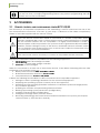
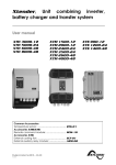
VarioString
MPPT solar charge controller
User manual
VarioString
VS - 120
48V- 120A
Accessories:
Remote control……………………………………. RCC-02/03
Temperature sensor…....…………………………. BTS-01
External auxiliary relay module...………………. ARM-02
Studer Innotec SA 2014
4O9P
V 1.2.1
Studer Innotec SA
VarioString
2
V 1.2.1
User manual
Studer Innotec SA
VarioString
Contents
1
2
3
4
5
6
7
8
INTRODUCTION ...................................................................................................................................... 5
GENERAL INFORMATION ....................................................................................................................... 5
2.1
About this user manual ....................................................................................................................... 5
2.2
Important safety instructions .............................................................................................................. 6
2.3
Conventions .......................................................................................................................................... 6
2.4
Quality and warranty .......................................................................................................................... 7
2.4.1
Exclusion of warranty .................................................................................................................. 7
2.4.2
Exclusion of liability ...................................................................................................................... 7
2.5
Warnings and guidelines .................................................................................................................... 8
MOUNTING AND INSTALLATION ........................................................................................................... 8
3.1
Storage .................................................................................................................................................. 8
3.2
Unpacking ............................................................................................................................................. 8
3.3
Mounting place.................................................................................................................................... 9
3.4
Fixing/Dimensions ................................................................................................................................. 9
WIRING ................................................................................................................................................. 10
4.1
Elements of the cable compartment ............................................................................................ 10
4.2
Connecting the battery ................................................................................................................... 12
4.2.1
Precautions when using the batteries ................................................................................... 12
4.2.2
Connecting the battery ........................................................................................................... 13
4.2.3
Protection device of the battery ........................................................................................... 13
4.3
Photovoltaic generator (PV) ........................................................................................................... 14
4.3.1
Dimensioning .............................................................................................................................. 14
4.3.2
Serial connection (chain or string) of PV modules ............................................................. 14
4.3.3
Parallel connection of PV module strings ............................................................................. 14
4.3.4
Safe use of the photovoltaic modules .................................................................................. 15
4.3.5
Protection devices .................................................................................................................... 15
4.3.6
Cable cross-section and connection ................................................................................... 15
4.3.7
Parallel connection of several VarioString ........................................................................... 15
4.3.8
Extension of an existing installation ........................................................................................ 16
4.4
Earthing ................................................................................................................................................ 16
4.4.1
Detecting an earthing fault .................................................................................................... 17
4.5
Lightning protection .......................................................................................................................... 17
4.6
Connecting the communication cables ...................................................................................... 17
POWER-UP OF THE EQUIPMENT ........................................................................................................... 18
DISPLAY SYSTEM ................................................................................................................................... 19
6.1
The “SET” button (4) ........................................................................................................................... 19
6.2
“Night” standby indicator (1) .......................................................................................................... 19
6.3
“Charge” cycle indicator (2) .......................................................................................................... 19
6.4
“Error” indicator (3) ............................................................................................................................ 20
6.5
Charging current Indicator (5)-(6)-(7)-(8)-(9)-(10) ....................................................................... 20
BATTERY CHARGING PROCESS ........................................................................................................... 21
7.1
General points .................................................................................................................................... 21
7.2
Battery cycle ....................................................................................................................................... 21
7.2.1
Bulk phase (1) ............................................................................................................................. 21
7.2.2
Absorption phase (2) ................................................................................................................ 21
7.2.3
Floating phase (4) ..................................................................................................................... 21
7.2.4
Equalization phase (3) .............................................................................................................. 21
7.2.5
Temperature compensation ................................................................................................... 22
7.3
Default battery charge cycle (original settings) ......................................................................... 22
7.4
Recovery after deep discharge ..................................................................................................... 22
CONFIGURING THE VARIOSTRING(S) ................................................................................................. 23
8.1
Configuring the equipment by means of the internal DIP switches ........................................ 23
8.2
Displaying the equipment status using the remote control RCC-02/03.................................. 25
8.2.1
Displaying the status of a single unit system ........................................................................ 25
8.2.2
Displaying the operating mode of the equipment (Info n° 15013,15014,15015) .......... 27
8.2.3
Displaying security errors (Info n° 15049) ............................................................................... 27
User manual
V 1.2.1
3
Studer Innotec SA
VarioString
8.2.4
Displaying the values of a multi-unit system ........................................................................ 28
8.2.5
Displaying messages and event history ................................................................................ 28
8.3
Configuring the VarioString using the remote control RCC-02/03 ........................................... 28
8.3.1
The real time clock .................................................................................................................... 29
8.4
Description of the VarioString parameters .................................................................................... 29
8.4.1
Convention ................................................................................................................................. 29
8.4.2
Parameter access level ........................................................................................................... 29
8.4.3
Organisation of the VarioString configuration menu ......................................................... 30
8.4.4
Basic settings {14000} ................................................................................................................ 31
8.4.5
Battery management and cycle {14003} ............................................................................. 32
8.4.6
System {14037} ........................................................................................................................... 35
8.4.7
Auxiliary contacts 1 {14070} and 2 {14122} ........................................................................... 37
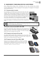
9
ACCESSORIES ...................................................................................................................................... 40
9.1
Remote control and programming centre RCC-02/03 .............................................................. 40
9.2
Temperature sensor BTS-01 ............................................................................................................... 41
9.2.1
Connecting the temperature sensor (BTS-01) ..................................................................... 42
9.3
Auxiliary relay module ARM-02........................................................................................................ 42
9.4
Parallel connection cable ............................................................................................................... 42
10 EQUIPMENTS COMPATIBLE WITH THE VARIOSTRING ......................................................................... 43
10.1
Xtender inverter/chargers ................................................................................................................ 43
10.2
Battery status processor BSP- 500/1200 .......................................................................................... 43
10.3
Communication module Xcom-232i.............................................................................................. 43
10.4
Communication sets Xcom-LAN/-GSM ......................................................................................... 43
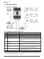
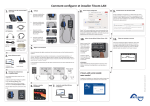
11 WIRING EXAMPLES .............................................................................................................................. 44
11.1
VarioString + RCC-02 ......................................................................................................................... 44
11.2
Comments on the wiring examples 11.1 ....................................................................................... 44
12 MAINTENANCE OF THE INSTALLATION ............................................................................................... 45
13 PRODUCT RECYCLING ......................................................................................................................... 45
14 EC DECLARATION OF CONFORMITY .................................................................................................. 45
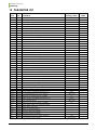
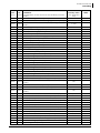
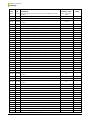
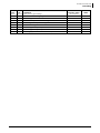
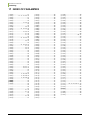
15 PARAMETER LIST ................................................................................................................................... 46
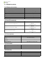
16 TECHNICAL DATA ................................................................................................................................ 50
16.1
General specifications ...................................................................................................................... 50
16.2
Input (PV generator) ......................................................................................................................... 50
16.3
Output (battery) ................................................................................................................................. 50
16.4
Environment ........................................................................................................................................ 50
16.5
Protection ............................................................................................................................................ 50
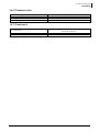
16.6
Communication ................................................................................................................................. 51
16.7
Compliance ........................................................................................................................................ 51
17 INDEX OF PARAMETERS ....................................................................................................................... 52
4
V 1.2.1
User manual
Studer Innotec SA
VarioString
1
INTRODUCTION
Congratulations! You are about to install and use a device from the VarioString range. You have
chosen high-tech equipment that will play a central role in the energy production of your solar
electrical installation. The VarioString has been designed to work as a solar battery charger; its
advanced and completely configurable functionalities will guarantee a perfect functioning of your
energy system.
When the VarioString is connected to batteries and photovoltaic panels, it automatically recharges
batteries in an optimum way with all the available solar power. The VarioString can be connected to
two strings of PV modules in different configurations (series, parallel, or independent). This
configuration flexibility allows the user to optimise their installation. The accuracy of the Maximum
Power Point Tracking (MPPT) algorithm, the high output and low internal consumption ensure an
optimal valorisation of the energy produced by the PV modules.
The charge profile may be set freely according to the battery type or the operation mode. The
charging voltage is corrected depending on the temperature thanks to the optional external sensor
BTS-01.
The control, display and programming unit RCC-02/03 (optional) allows an optimal setup of the
system and guarantees the user a permanent control over all important parameters for the
installation with a clear display interface. Moreover, it allows recording the system data in order to
analyse later its functioning (data logging).
The parallel operation of several chargers is possible and offers modularity and flexibility enabling an
optimum dimensioning of your system according to your energy requirements.
The VarioString operates as an independent device but is also designed to be included into a Studer
energy system together with the Xtender inverters/chargers, the BSP battery monitor, the control,
display and programming unit RCC-02/03, the communication modules Xcom-232i and XcomLAN/GSM. Working together, these different devices have a synchronised behaviour for a better
management of the battery and of the solar resource.
Please read this manual carefully to ensure the perfect start up and operation of your system. It
contains all necessary information regarding the operation of the VarioString charger. The installation
of such a system requires special expertise and may only be carried out by qualified personnel
familiar with the local standards in force.
2
2.1
GENERAL INFORMATION
ABOUT THIS USER MANUAL
This manual contains necessary information and procedures to install, configure, use and
troubleshoot the VarioString solar charge controllers. It does not contain information about
photovoltaic modules (PV) or batteries of various brands that can be connected. For this kind of
information, please refer to the instructions of each specific manufacturer.
It covers the following models and accessories:
MPPT solar charge controller : VarioString VS-120
Temperature sensor : BTS-01
External auxiliary relay module : ARM-02
This manual is an integral part of the equipment and must be available for the operator
and/or the installer at all times. Always keep it close to the installation.
User manual
V 1.2.1
5
Studer Innotec SA
VarioString
2.2
IMPORTANT SAFETY INSTRUCTIONS
This manual contains important safety instructions. Read carefully the safety and operation
instructions before using the VarioString. Take into consideration all warnings mentioned both on the
equipment and in this manual, strictly following all instructions regarding its operation and use.
This user manual is intended to serve as a guideline for the safe and efficient use of the VarioString.
Anyone who installs or uses a VarioString can completely rely on this user manual and is bound to
observe all the safety instructions and indications here in.
The installation and commissioning of the VarioString must be entrusted to qualified personnel. The
installation and use must comply with the local safety instructions and standards in force in the
country.
2.3
CONVENTIONS
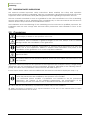
This symbol is used to indicate safety instructions which, if not followed, could result in serious
personal injury or death to the operator or the user.
This symbol is used to indicate a general danger for the user and/or a risk of material
damage and/or the cancellation of the guarantee.
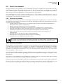
This symbol is used to indicate a procedure or function that is important for a safe and
correct use of the equipment. Failure to respect these instructions may lead to the
cancellation of the guarantee or to a non-compliant installation.
This symbol placed on the product indicates that its surfaces may reach temperatures
higher than 60°C.
This symbol placed on the product indicates that its use must follow the instructions in the
user’s manual.
In general, values important for the operation of the equipment (for example: battery voltage during
absorption) are not mentioned and the parameter number is indicated in the following format:
{xxxxx}. The value of the parameter can be found in the table chap. 15.
In most cases, these values can be modified with the remote control RCC-02/03 (see chap. 9.1).
The parameter table available at the end of this manual (chapter 15) must be kept updated
in case the parameters are modified by the operator or the installer.
If an authorised person modifies a parameter not included in the list (advanced
parameters), the number of the modified parameter(s), the specifications of the
parameter(s) and the new value set are to be indicated at the end of the table.
All values that are not followed by a parameter number may not be modified.
All digits and letters in brackets or in square brackets in the text of this manual refer to items
represented in illustrations with a circle.
6
V 1.2.1
User manual
Studer Innotec SA
VarioString
2.4
QUALITY AND WARRANTY
During production and assembly of the VarioString, each unit undergoes several checks and tests
which strictly comply with established procedures. The manufacturing, assembling and testing of
each VarioString are completely carried out in our factory in Sion (CH). The equipment warranty
depends upon the strict application of the instructions in this manual.
The VarioString MPPT solar charge controller has a 5-year warranty (starting from the date of
production against material and manufacturing faults). A defective product will either be repaired
or replaced at the discretion of Studer Innotec.
2.4.1 Exclusion of warranty
No warranty claims will be accepted for damages resulting from handling, use or treatment that are
not explicitly mentioned in this manual. In particular, damages arising from the following causes are
excluded from the warranty:
Voltage higher than 600V across PV terminals (independent or parallel configuration) or
higher than 900V (series configuration).
Battery reversed polarity across PV input terminals.
Accidental presence of liquids in the equipment or oxidation due to condensation.
Damage resulting from falls, mechanical shocks or permanent or excessive vibrations.
Modifications carried out without the explicit authorisation of Studer Innotec.
Nuts or screws that have not been tightened sufficiently during the installation or
maintenance.
Damage due to atmospheric surge voltage (lightning).
Damage due to inappropriate transportation or packaging.
Disappearance of original identification marks.
Never take off or damage the rating plate showing the serial number. It enables to check
and follow-up the data specific to each equipment and is vital for any warranty claim.
2.4.2 Exclusion of liability
The installation, commissioning, use, maintenance and servicing of the VarioString cannot be subject
of monitoring by Studer Innotec. Therefore, we disclaim all responsibility and liability for damage,
costs or losses resulting from an installation that does not comply with the instructions, a faulty
operation or inadequate maintenance. The use of Studer Innotec equipment is in any case under
the responsibility of the customer.
This equipment is neither designed nor guaranteed to supply installations used for vital medical care
nor any other critical installation entailing potential risks of important damage to people or to the
environment.
We assume no responsibility for the infringement of patent rights or other third parties rights resulting
from the use of the MPPT solar charge controller VarioString.
Studer Innotec reserves the right to make any modifications to the product without prior notification.
Studer Innotec is not liable for incidental, direct or indirect damages of any kind, including any profit
loss, revenue loss or damages caused to equipment or goods due to defective equipment.
User manual
V 1.2.1
7
Studer Innotec SA
VarioString
2.5
WARNINGS AND GUIDELINES
The installation and commissioning of the VarioString must be entrusted to skilled and qualified
personnel perfectly aware of the safety precautions and local rules in force. All elements connected
to the VarioString must comply with the laws and regulations in force.
HIGH-VOLTAGE DC INSIDE THE CHARGE REGULATOR: DANGER OF DEATH
When the VarioString is in operation it generates voltages that can be potentially lethal (up
to 1000Vdc). Any work on or close to the installation must only be carried out by thoroughly
trained and qualified personnel. Do not try to carry out ordinary maintenance on this
product yourself.
While working on the electrical installation, it is important to make sure that the source of
DC voltage coming from the battery as well as the source of DC voltage coming from the
photovoltaic generator, have been disconnected from the electrical installation.
Even when the VarioString has been disconnected from the power sources, a potentially
dangerous voltage may remain at the terminals. To eliminate this you have to wait for at least
5 minutes in order to allow the electronics to discharge. The task can then be carried out safely.
No person is authorized to proceed with any change, modification or repair of the equipment without
prior written authorisation from Studer Innotec. Only original parts should be used in authorised
modifications or replacements.
Respect the maximum rated specifications of the equipment indicated on the type label.
The VarioString can be installed at altitudes up to 3000m. For installations at higher
altitudes, please contact Studer Innotec SA. The VarioString is in overvoltage category
II, in accordance with the norm IEC/EN 62109-1:2010 that considers all solar generators
as being in overvoltage category II.
3
MOUNTING AND INSTALLATION
The wiring and connection of the installation must be carried out only by perfectly qualified
personnel. The installation material such as cables, connectors, distribution boxes, fuses,
etc., must be appropriate and comply with the laws and regulations in force for the
application in question.
3.1
STORAGE
The equipment must be stored in a dry environment at an ambient temperature between -20°C and
60°C. Place the equipment at its mounting place at least 24 hours before commissioning in order to
avoid thermal shocks and condensation problems.
3.2
UNPACKING
When unpacking, check that the VarioString has not been damaged during transportation and that
all accessories listed below are present. Any fault must be immediately reported to the product
distributor or the contact mentioned at the back of this manual.
Carefully check the packaging as well as the VarioString.
Contents in the VarioString box:
VarioString
Installation and operation manual
Cable-glands for the battery cables
Two pairs of solar cable connectors
8
V 1.2.1
User manual
Studer Innotec SA
VarioString
3.3
MOUNTING PLACE
The mounting place for the VarioString is particularly important and must fulfil the following criteria:
Indoors (IP20).
Protected from water and dust in a location without condensation.
Protected from any unauthorized person.
In a place where the relative humidity does not exceed 95%
In a place where the ambient temperature is between -20 and 55°C
In mobile applications, it is important to select a mounting place that ensures no vibration.
Protected from direct solar radiation or heat sources.
It should not be mounted directly above the battery or in a cabinet with the battery
The ventilation vents should be clear at all times and at least 20 cm from all obstacles that
could alter the ventilation of the device.
Given the norm IEC/EN 62109-1, the degree of pollution in the installation area should be at
maximum PD2.
The support for the VarioString and the environment in which it is contained should not be
flammable.
The presence of a heat source may significantly reduce its rated power. Similarly, insufficient
ventilation may lead to the overheating of some internal components of the equipment. In this case,
the device will automatically limit its power as long as this abnormal situation persists.
As far as possible, reduce exposure to sudden temperature variation: important heat variation may
create undesired and harmful condensation inside the equipment.
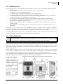
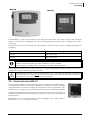
3.4
FIXING/DIMENSIONS
The VarioString is a heavy equipment (~8kg) and must be mounted to a support (wall)
designed to bear such a load. It is imperative to ensure a complete and safe fastening of
the equipment. If simply hung, it may fall down and cause severe damages.
Upper support screw: screw into the wall a 6-8 mm diameter screw without washer until there is 2 mm
between the head of the screw and the wall. Hang the device from the screw. If deemed necessary,
the upper support screw can be fully tightened after hanging the device. In theory this is only
necessary in mobile applications. To access the upper support screw to fully tighten it, remove the
upper plastic grate.
Lower support screws: remove the lower plastic grate which gives access to the cabling
compartment. Carefully fix the device to the support with two screws (6-8 mm in diameter) using the
two mounting holes located at the bottom left and right of the cabling compartment.
The VarioString must be installed vertically. A distance of at least 5cm between the units and/or 20cm
around the equipment is required to guarantee adequate ventilation.
If the VarioString is
installed in a closed
cabinet, it must have a
sufficient ventilation to
guarantee that the
ambient temperature
is kept within the
operating limits of the
VarioString.
In motor vehicles, or
when the support
undergoes significant
vibrations,
the
VarioString is to be
mounted on antivibration elements.
User manual
V 1.2.1
9
Studer Innotec SA
VarioString
4
WIRING
The connection of the VarioString charger is an important step of the installation.
It may only be carried out by qualified personnel, aware of the rules and regulations in force.
The installation must always comply with these standards. The cross-sections of the cables
connected to its terminals must comply with local regulations. All cables in use should be
isolated with PVC, TFE, PTFE, FEP, neoprene or polyimide.
Make sure that connections are completely tightened and that each wire is connected at
the right place.
The VarioString is intended to be connected exclusively to a source like a photovoltaic
generator, excluding any other energy source.
It is suitable for charging any type of lead-acid batteries. It is often possible to charge any
other type of battery using proper settings and with the express approval of the battery
supplier.
The connection compartment of the VarioString must remain permanently closed while the
apparatus is operating.
Before opening, check that all voltage sources (battery and PV) have been disconnected
or switched off and wait for at least 5 minutes before opening the equipment. It is imperative
to close the protection cover on the connection terminals after each servicing.
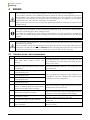
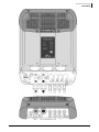
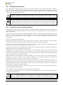
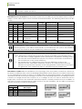
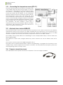
4.1
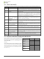
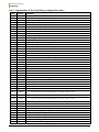
ELEMENTS OF THE CABLE COMPARTMENT
No.
Description
1
Terminal to connect the battery positive
pole (M8, 8Nm torque, PG-21 (1318mm))
2
3
4
5
6
7
Terminal to connect the battery
negative pole (M8, 8Nm torque, PG-21
(13-18mm))
Connector (Sunclix) for negative pole of
solar generator n°2.
Connector (Sunclix) for positive pole of
solar generator n°2.
Connector (Sunclix) for negative pole of
solar generator n°1.
Connector (Sunclix) for positive pole of
solar generator n°1.
Socket for connection of accessories
BTS-01 or ARM-02 (battery temperature
sensor and auxiliary relay module)
8
Socket for communication cables and
the remote control RCC-02/03.
9
Termination switch
10
Configuration switches (DIP-switch)
11
Real-time clock battery
(type CR 2032)
10
Comments
This connection must be done using a protection
and disconnection device if the pole has not
been earthed. For mounting of the internal fuse,
refer to sect. 4.2.2
This connection must be done using a protection
and disconnection device if the pole has not
been earthed.
The solar generator wiring must be carried out in
compliance with the voltage and current limits
mentioned on the rating plate.
Only the mentioned original accessories can be
connected to this connector.
RJ45 connector used for connecting equipment
of the Xtender family. These connections must be
carried out only with original Studer cables.
The switch must be placed in position O (towards
(8)) when both connectors are used.
The various possible configurations are described
in sect. 8.1
The equipment is fitted with a battery lasting
about 10 years.
V 1.2.1
User manual
Studer Innotec SA
VarioString
User manual
V 1.2.1
11
Studer Innotec SA
VarioString
4.2
CONNECTING THE BATTERY
The VarioString is a device which DC (battery) connection is to be connected exclusively to a battery.
Most of the time, lead-acid batteries with liquid (VLA, VRLA) or gelled (GEL) and AGM electrolyte
may be used. It can be easily configured to create charge profiles that are compatible with these
various types of lead-acid batteries.
Using the VarioString connected to any other type of DC source without battery is strictly
forbidden and may cause significant damage to the equipment and / or to the source.
The use of other battery types like Ni-Cd, Li-ion or other is possible if the charge profile is
properly programmed, in accordance with the specifications of the battery manufacturer,
in agreement with the battery manufacturer and under the responsibility of the installer.
4.2.1
Precautions when using the batteries
The batteries should only be chosen, dimensioned and installed by qualified personnel, trained in this
specific area. When working with batteries, a second person is required in order to give assistance in
case of problems.
Lead-acid batteries with liquid or gelled electrolyte produce a highly explosive gas during normal
use. Avoid source of sparks or fire in the immediate vicinity of the batteries. The batteries must be
kept in a well-ventilated place and installed so as to avoid accidental short-circuits when
connecting.
Never try to charge frozen batteries.
Sufficient fresh water and soap must be kept close at hand to allow adequate and immediate
washing of the skin or eyes affected by accidental contact with the battery acid.
In the event of accidental contact of the eyes with acid, they must be washed carefully with cold
water for 15 minutes. Then immediately consult a doctor.
The battery acid can be neutralized with baking soda, among other things. A sufficient quantity of
baking soda should be available for this purpose.
Particular care is required when working close to the batteries with metal tools. Tools such as
screwdrivers, open-ended spanners, etc., may cause short circuits. Sparks created by short-circuits
may cause the battery to explode. Therefore these kinds of tools must always have isolated handles
and never be placed on top of a battery.
When working with the batteries, all metal jewellery such as rings, watches with a metal bracelet,
earrings, etc., must be taken off. The current supplied by the batteries during a short circuit is
sufficiently powerful to melt the metal and cause severe burns.
Batteries at the end of their life-cycle should be recycled in accordance with directives from the
responsible local authorities or the battery supplier. The batteries should never be thrown into fire as
they may explode. Under no circumstances should you try to take apart or dismount the battery, as
they contain toxic and polluting materials.
For ungrounded battery systems, always check that they are not inadvertently grounded before
starting working on the batteries.
Always follow carefully the instructions of the battery manufacturer.
If the battery voltage exceeds the value of 68V, the charger turns off and starts again when the
voltage is lower than 64V.
A battery voltage higher than 80V can cause important damage or destroy the equipment.
Such a voltage applied on equipment connected downstream like Xtender
inverters/chargers or other, can cause important damage or destroy the equipment!
12
V 1.2.1
User manual
Studer Innotec SA
VarioString
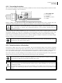
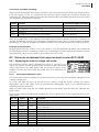
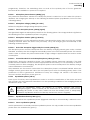
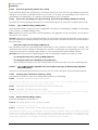
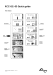
4.2.2 Connecting the battery
All connection cables as well as the battery cables must be mounted using cable restraints in order
to avoid any pulling on the connection.
a = M10 cable lug!!
b = bolt M8x30
c = washer
d = ceramic washer
e = fusible
Battery cables must also be as short as possible and the cross-section must comply with the
regulations and standards in force. Tighten the clamps on the “Battery” inputs sufficiently.
Each VarioString is connected directly to the battery using its own protective device. All
other consumers or sources are connected directly to the battery through their own
protective device.
Lead batteries are usually available in 2V, 6V or 12V blocks. In most cases, in order to get the correct
operating voltage for using the VarioString, several batteries must be connected in series. The
capacity of the batteries can be increased using a parallel connection of several battery strings.
Some battery manufacturers limit the use or advice against parallel connection of battery strings.
Strictly conform to the manufacturer's instructions of use.
In multi-unit systems (connected to the same communication bus), all VarioStrings must be
connected to the same battery bank.
4.2.3 Protection device of the battery
The battery cables must be as short as possible. The recommended cable cross-section is 50mm2
and the protection devices (battery side) must be 125A. The protection device must be installed as
close as possible to the battery. The recommended cross-section of battery cable is valid for lengths
up to 3m. Beyond this length, it is recommended to oversize the section of the battery cables.
Any other sources or loads existing on the battery must be connected using their own protection
devices. Never connect them to the protection device(s) of the VarioString.
An annual check of all the connection tightness is recommended. In mobile installations,
the connection tightness should be checked more often.
Battery cables must always be protected by one of the following measures:
Have a protection and disconnection device (fuse, circuit breaker) on the pole not
connected to earth.
The protection device must be rated according to the cable cross-section but must not
exceed 1.25 x VarioString maximum current. It will be mounted as close as possible to the
battery.
User manual
V 1.2.1
13
Studer Innotec SA
VarioString
4.3
PHOTOVOLTAIC GENERATOR (PV)
The VarioString may accept the following maximum input voltages:
600 V max for independent and parallel cabling
900 V max for series cabling
The whole solar system must be installed according to protection class II.
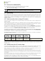
4.3.1 Dimensioning
The solar generator is dimensioned to cover an important part or the entire power requirement of the
system. Once the power has been decided upon, it will be distributed among one or more solar
charge regulators, wisely combining the modules among them. These combinations in series and in
parallel must be carried out according to the voltage and current limits of the VarioString solar
charge controller.
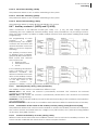
4.3.2 Serial connection (chain or string) of PV modules
To get the optimum voltage, the PV modules shall be connected in series to form a string with the
desired voltage.
When using the two entries in series, the + terminal of the PV1 entry (6) should be connected to the
+ pole of the PV generator. The – terminal of the PV2 entry (3) should be connected to the – pole of
the PV generator and a bridge should be made between the entries (4) and (5).
The open-circuit voltage of the string must be lower than 600V under any temperature and irradiation
conditions. A 10 to 20% margin is recommended in order to cover these unknowns. When the two
inputs are used in series, the maximum open-circuit voltage should not surpass 900V.
To establish the maximum numbers of the PV modules connected in series in the same string, use the
following formula: 600V/(Uoc*1.1). (Example: 600/(22*1.1)=24.79). The result must be rounded down
(i.e. 24 modules - of 22 Voc - in series for the above example).
The table below gives an idea of the possible arrangements for common PV modules according to
the number of cells or their type:
36 cell
module
Voc < 23V
max.
60 cell
module
Voc < 37 V
max.
72 cell
module
Voc < 45V
max.
Thin film
module
Voc < 110V
--
23
14
12
4
35
22
18
8
For independent or parallel
inputs
For the two inputs in series
Beware of the PV module temperature! The above values are for modules under standard test
condition (STC).
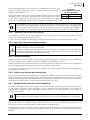
4.3.3 Parallel connection of PV module strings
To get the required charging power, 2 or more strings can be connected in parallel. Each string
connected in parallel shall be composed of the same number of modules of the same type.
When using the two entries in parallel (up to 26A) it is necessary to physically connect the two
negative terminals (3) and (5) as well as the two positive terminals (4) and (6).
The number of strings connected in parallel depends on the power of each module. The sum of the
power of all the panels connected to a VarioString should not exceed the power that the VarioString
can charge.
The number of strings to be connected in parallel must not exceed the maximum power (see table
below) divided by the power of a string and rounded down to the nearest whole number.
For example, with 12 modules of 110W in series connected to one of the independent inputs:
3500/1320=2.65 => 2 strings (2640W) can be connected in parallel.
14
V 1.2.1
User manual
Studer Innotec SA
VarioString
If both VarioString inputs are connected in parallel, for the strings of 12
modules in series mentioned above, 5 strings could be connected in
parallel (7000/1320=5.3 =>5).
Maximum
recommended power for
the solar generator
Battery VS-120
48V
3500W/input
The PV generator can be over-dimensioned in order to get the required
charging power even when solar irradiation is lower. In this case, a part
of the solar energy will be lost when the solar irradiation is higher
because the VarioString will reach its current limit and curtail power output.
The VarioString has a current limit. At any given time, the maximum power of the VarioString
depends on the charging phase voltage of the battery. For example, if the charging phase
is Bulk, and the battery voltage is 50V, the maximum power output is 120A * 50V = 6000VA.
Even if more solar energy is available, the battery charge current will not exceed 120A.
4.3.3.1
Maximum current of the solar generator
The maximum current of the solar generator (sum of the short-circuit currents for all the strings
connected in parallel) is 26A (13A per input).
In any case, the VarioString will limit the charging current (battery) to its rated current of 120A.
4.3.4 Safe use of the photovoltaic modules
The VarioString is meant for PV generators supplying up to 600Vdc (900Vdc in series). This
voltage is dangerous for human beings.
During the installation or the maintenance of the system, it is imperative to make sure that
no dangerous voltage may surge in the system. The disconnection device must be open
and secured against any accidental reclosing.
4.3.5 Protection devices
Wiring protection devices (fuses, circuit breakers) connecting the PV generator to the VarioString
must be installed in accordance with local standards and regulations in force.
The DIN VDE 0100-712 standard prescribes a switching device on all poles between the PV generator
and the charge regulator. This device must be supplied by the installer.
PV modules are often exposed to stormy weather. It is highly recommended to install lightning
protection (see chap. 4.5).
4.3.6 Cable cross-section and connection
The connection cable cross-section must be chosen according to the short-circuit current of the PV
generator and the local installation rules. The Sunclix type PV connectors do not need any special
tools for mounting. They accept cables between 2.5 and 6mm2 (exterior cross section of 5 to 8mm2).
The length of cable to strip to attach the Sunclix connector is 15mm.
4.3.7 Parallel connection of several VarioString
As many VarioString as necessary can be connected in parallel on the same battery bank according
to the battery capacity. Each will have its own independent solar generator (connected in
independent, parallel or series configuration) and include its own disconnection and protection
device to the battery.
Under no circumstances should PV module inputs of several VarioString be put in parallel.
Up to 15 VarioString could be synchronized and interconnected to the same communication bus
(see chap. 4.6) on a single system. Beyond these 15 units, any additional unit will not be
interconnected and thus their battery cycles will work independently.
Solar generators may be of various types and be orientated differently. Each VarioString will adjust
the optimum point of the PV generator independently of the other units connected to the same
battery.
User manual
V 1.2.1
15
Studer Innotec SA
VarioString
In multi-unit systems (connected to the same communication bus), all VarioStrings must be
connected to the same battery bank.
When the VarioString units are not synchronized, they must be programmed in the same
way and it is recommended to not activate the periodical equalization function. The
equalization can be manually started or will be done by the synchronized units.
For multi-unit systems, the devices are connected to each other by a communication bus (see chap.
4.6) via the connectors (7) and a cable (ref. CAB-RJ45-8-2) with a maximum length of 5 meters.
As long as they are correctly connected together by the communication cable, the VarioString
automatically synchronize the battery charge cycle.
When the devices are in the voltage regulation phase, their currents current may
considerably differ. These differences have no effect at all on the charge quality.
If a VarioString is connected to another compatible device (Xtender, VarioTrack, VarioString,
BSP, RCC, Xcom) with the same communication bus, it is highly recommended to make a
software update of all components in the system in order to guarantee all functionalities.
During the commissioning of the equipment in a multi-unit configuration, the system checks
automatically the compatibility of the software versions and may prevent the operation in
case of incompatibility. An upgrade of the installation must then be carried out by means
of the RCC-02/03 remote control using the latest manufacturer's software version (read the
user manual for the control and monitoring unit RCC-02/03 to carry out this operation).
4.3.8 Extension of an existing installation
In interconnected installations, if the software is compatible, it is possible to extend an existing
installation by adding one or several (up to 15) VarioString units in parallel.
4.4
EARTHING
The VarioString is a Class I protection equipment, its metal case must be
earthed by means of the grounding screw, included for that purpose.
= protective earth (connected to the enclosure of the equipment).
The solar generator (as well as its wiring) must be Class II isolated.
The cross-section of the earthed cable must not be less than 16mm2.
The whole solar system must be installed according to protection class II.
In any case, the protective earth must be connected in accordance with local standards and regulations
in force. The protective earth of the equipment must at least be connected to the earthed ground of all
the Class I equipment after and before the VarioString (equipotential connection). The information, notes,
recommendations and diagrams reported in this manual are subject to local installation rules. The installer
is responsible for the conformity of the installation with the local standards in force.
16
V 1.2.1
User manual
Studer Innotec SA
VarioString
4.4.1 Detecting an earthing fault
The choice of earthing system for the DC circuit is an important factor for the individuals' safety. Once
the decision is made the VarioString can check the continuity of the earth connection.
In case of failure of this connection, the equipment turns off and the LED (3) lights up indicating the
fault. A permanent message (requiring a validation) is displayed on the RCC if present.
The parameters {14040}, {14041} and {14042} allow establishing the type of control to be carried out
or the absence of control as set by default.
4.5
LIGHTNING PROTECTION
The VarioString has internal protections against lightning by means of surge protection devices. These
devices have an energy dissipation capacity limited to 3,5kA (8x20 µs) which guarantees a certain
protection level but are not a total protection against lightning. According to the installation site, it is
highly recommended to develop a protection strategy specific to your installation. The strategies
depend on various factors specific to each site; therefore we recommend a professional approach
to this issue.
Damages due to lightning often generate significant costs (replacement of all electronics)
which are not covered by the manufacturer's warranty.
4.6
CONNECTING THE COMMUNICATION CABLES
The VarioString is fitted with 2 connectors RJ45/8 (8) (see chap. 4.1) that enable to transfer information
via a communication bus to other VarioStrings or to other equipment such as the RCC, the BSP or the
Xcom having the proprietary protocol of Studer Innotec. In this case, the installation should be
stopped and de-energized (the protection devices of power sources and loads should be open) to
complete the cable connection and positioning of the termination switches of all the devices
connected to the communication bus.
The termination switch of the communication bus "Com. Bus" (9) remains in position T
(terminated) except when both connectors are used. In this case and only in this case, the
switch must be placed in the O (open) position. If one of the two connectors is not used,
the termination switch (9) will be in position T.
The max accumulated length of the communication bus is 300m. Due to a line voltage drop, it is
recommended to install only one RCC module at the end of a 300m line or a max of 2 modules at
the end of a 150m line. All the other modules of the system must be placed within the same radius of
a few meters (technical room).
A maximum of 3 RCC-02/03 or Xcom-232i may be connected to the same communication
line with a VarioString.
If a VarioString is connected to another compatible device (Xtender, VarioTrack, BSP, RCC,
Xcom) with the same communication bus, it is highly recommended to make a software
update of all components in the system in order to guarantee all functionalities.
User manual
V 1.2.1
17
Studer Innotec SA
VarioString
The RCC-02/03 or Xcom-232i should not be placed between two devices connected to
the battery (Xtender, VarioTrack, or VarioString).
5
POWER-UP OF THE EQUIPMENT
It is imperative that the closing cover for the connection compartment is installed and
screwed tight before energizing the installation. There are dangerous voltages inside the
cable compartment.
If special configurations or settings are required for the system and they are set via internal
buttons or switches (DIP switch, see chap. 8.1), they should be set before connecting the
PV modules.
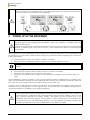
The connection of the VarioString must be carried out in the following order. Any disassembly shall
be carried out in the reverse order. Before closing the protections and energizing the equipment,
check the polarity.
A. Connecting the battery: on the BAT+ and BAT- terminals
Check that the VarioString switches on (green LED “NIGHT” lights up on the
Une étincelle apparait au moment de brancher le deuxième pôle de la batterie. Ceci est
normal.
B. Connecting the photovoltaic panels: on the PV+ and PV- terminals
Check the PV voltage seen on the RCC. (if present)
Check the operation of the charger and the effective charging of the batteries when it is
sunny.
Your installation is now in operation. If the system requires specific configurations or settings, carry
them out immediately. Settings must be programmed by means of the remote control RCC-02/03 as
per chap. 8.2 or by means of the internal DIP switches as per chap. 8.1.
Saving of data in the datalog is activated only after the VarioString has completed the automatic
detection of the cabling type of the PV generators. In the case that the cabling configuration is
entered manually, the datalog is activated immediately.
If the VarioString has been accidentally connected in reverse (battery reverse polarity on
the panel input), it is likely that the protection device on the battery cables is open. In such
case, recheck carefully the battery polarity, the wiring and the internal fuse of the
VarioString that protects against this situation. If after having closed or replaced the
protection device (f), the VarioString still does not work despite the correct polarity and
voltage of the battery, it must be brought back to the Seller for repair.
18
V 1.2.1
User manual
Studer Innotec SA
VarioString
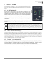
6
DISPLAY SYSTEM
The VarioString is fitted with a “Set” button and light indicators on the
front of the equipment allowing a clear identification of the operating
mode.
6.1
THE “SET” BUTTON (4)
The “Set” button can be used to start manually an equalization cycle
if this phase is authorized by the initial settings of the equipment. The
equalization phase will be authorized as from the beep after having
pressed the “Set” button (4) for 2 seconds. The “Charge” light indicator
flashes 3x as long as the equalization phase is not completed. The
equalization can be interrupted by pressing a second time for 2
seconds: a double beep indicates that the function has been
cancelled. The indicator (2) stops flashing 3x confirming the
cancellation.
Pressing the “Set” button (4) for 5 seconds until the second beep turns
off the VarioString. It starts again by pressing the “Set” button for 5
seconds.
When the VarioStrings(s) are connected to an Xtender system and the synchronization
{10037} is activated, the manual equalization can be started only during the battery cycle
of the Xtender which will then pilot the VarioString to carry out an equalization phase. In
“synchronized” mode, the cycle state - floating, absorption, equalization - are indicated. The
“charge” LED (2) and the indicator for the amount of charge are used when the equipment
is operating.
6.2
“NIGHT” STANDBY INDICATOR (1)
This green indicator lights up when the VarioString is connected to a battery and ready to operate
but there is no PV voltage (at night or when no PV module is connected) or it is too low (inferior to
the battery voltage). This indicator flashes when there is a PV voltage but it is insufficient to charge
the batteries (at the beginning or at the end of the day). In order to save the battery power, the
VarioString charger turns off and goes in standby mode when this indicator lights up or flashes. It will
then consume less than 1W. The charger automatically switches on again when the sun starts shining
and PV voltage goes back above the battery voltage.
6.3
“CHARGE” CYCLE INDICATOR (2)
This yellow indicator lights up when the sun is shining and the photovoltaic generator produces
enough voltage for charging the batteries. Various flashing modes enable to distinguish in what
phase the regulator is. This indicator lights up continuously during the bulk phase. It flashes 1x during
the floating phase, 2x during the absorption phase and 3x during the equalization phase.
In “synchronized” mode, the cycle state – bulk, floating, absorption, equalization - are indicated.
User manual
V 1.2.1
19
Studer Innotec SA
VarioString
6.4
“ERROR” INDICATOR (3)
The table below describes the type of error according to the number of times this indicator blinks red.
Indic.
Indicated error
Comment
Off
No problem
If no indicator lights up, the equipment is de-energized.
On
The equipment is OFF
The equipment is energized but it does not operate because of
a user command (the “Set” button has been pressed for 5s).
Blinks
Battery
low
voltage The equipment is still operating but shows that the battery is
1x
warning
lower than 40V.
Blinks
Earth fault
The VarioString detects an abnormal situation which does not
2x
correspond to the programmed value of the parameter
{14040}, {14041} and {14042} checking the state of the earth
connection. The VarioString turns off. It automatically starts
again when the normal situation is restored.
Blinks
Power reduction or stop This may be due to an excessive ambient temperature,
3x
due to an excessive exposure of the equipment to a heat source (sun) or to
temperature
in
the deficient or impeded ventilation.
equipment.
Blinks
Battery voltage higher Check the cause of this excessive voltage. The equipment
4x
than 68V
automatically starts again when voltage returns to a value
lower than 64V.
Blinks
The PV voltage is higher The PV voltage exceeds the max limit (600V in parallel or
5x
than the set value of the independent, 900V in series). The equipment will stop or won’t
max operating limit.
start. See also chap. 4.3.2.
Blinks
Software incompatibility The different parts of the system’s equipment must have the
6x
in a system
same software version to function properly. Proceed with the
update following the procedure in the RCC-02/03 manual.
Blinks
Not used
7x
Blinks
The PV current is higher The PV current exceeds the max limit (13A in independent or in
8x
than the set value of the series, 26A in parallel). The equipment will stop or won’t start.
max operating limit.
See also chap. 4.3.3
Blinks
Error in cabling of PV The cabling specified by the parameter {14002} does not
9x
modules
correspond to the cabling detected by the device.
Blinks
Other errors
Internal error in system
10x
6.5
CHARGING CURRENT INDICATOR (5)-(6)-(7)-(8)-(9)-(10)
These indicators work as a type of histogram. They
blink or are lit up continually to indicate the range
of charge current from the VarioString given the
table to the right.
Indicator nr
LED (10)
LED (9)
Example:
For a charge current of 65 A, the LEDS (5, 6, and 7)
are lit up continuously while the LED (8) is blinking.
LED (8)
The RCC-02/03 remote control allows a complete
and detailed display of the VarioString's behaviour
(see chap. 9.1).
LED (7)
LED (6)
LED (5)
20
V 1.2.1
State
Lit
Blinking
Lit
Blinking
Lit
Blinking
Lit
Blinking
Lit
Blinking
Lit
Blinking
Signification
120A
100-120A
>100A
80-100A
>80A
60-80A
>60A
40-60A
>40A
20-40A
>20A
0-20A
User manual
Studer Innotec SA
VarioString
7
7.1
BATTERY CHARGING PROCESS
GENERAL POINTS
The VarioString has many parameters that can be modified by the user or the installer in order to
adapt the equipment to the energy system the best possible way. The factory values of these
parameters are reported in the table at the end of this manual.
These parameters can be modified by means of the remote control RCC-02/03 (optional) (see chap.
9.1– p. 40) and for some of them, a basic configuration can be done using the DIP switches (9) inside
the equipment (see chap. 8.1).
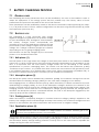
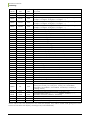
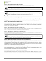
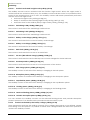
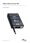
7.2
BATTERY CYCLE
The VarioString is a fully automatic solar charge
regulator designed to guarantee an optimum charge
for most lead/liquid acid, lead/gel or AGM batteries.
The battery charger enters automatically into
operation as soon as the irradiation is sufficient and the
photovoltaic panel voltage is higher than the battery
voltage. The “Charge” indicator (2) lights up or flashes
depending on the on-going charging phase.
The batteries can be fully charged by the successive
phases 1 to 4 described hereunder.
7.2.1 Bulk phase (1)
The bulk phase is the stage when the voltage of the battery rises thanks to the maximum available
current (up to 120 A) produced by the photovoltaic generator depending on the irradiation at the
time. It is important that the max battery charge current be set according to the battery
specifications to prevent damaging them. This current can be limited with parameter {14001}
“maximum output current”. It is possible that these currents are not reached if the generator power
is not sufficient because of its dimensioning, solar power, silicon temperature (crystalline cell), or
because the ambient temperature is excessive (or the ventilation is insufficient).
7.2.2 Absorption phase (2)
The absorption phase can be disabled by parameter {14008}. The maximum voltage that can be
reached will be the floating voltage {14005}. It is the case when charging a Li-Ion battery.
This charging phase, of a limited duration {14011}, allows the battery to absorb a maximum of power
while limiting its voltage {14009}. As soon as this absorption voltage is reached, the duration of the
phase is counted down as long as the voltage remains higher than the floating phase {14005}. If the
charging current is lower than the end of absorption voltage {14013} whereas the voltage limit is
reached, the absorption phase is considered finished. The end of the absorption triggered by the
current {14012} can be enabled if necessary.
7.2.3 Floating phase (4)
When the battery is completely charged, a constant reduced voltage {14005} is applied on the
battery. This voltage prevents self-discharge and keeps the battery at its maximum charge level and
reduces to the minimum the water evaporation that would occur at a higher voltage.
7.2.4 Equalization phase (3)
The default battery cycle is suitable for a large number of batteries, whether gel or not,
because the equalization phase is not activated.
This phase is allowed {14017} only for open batteries with liquid electrolyte. During this phase, the set
voltage limit for the battery {14021} is temporarily {14022} higher. It allows on one hand to equalize
the electrolyte density through mixing (corrosion control) and on the other hand to equalize the
charge among the cells of the battery.
User manual
V 1.2.1
21
Studer Innotec SA
VarioString
When this phase is authorized, it can be started manually by pressing for 2 seconds the “SET” button
on the front of the VarioString. The countdown for the equalization time starts as soon as the
equalization voltage {14021} is reached and lasts as long as the battery voltage is higher than the
absorption voltage {14009}.
When authorized, the equalization phase is carried out at fixed intervals {14023} before the absorption
phase. The equalization phase may be applied after the absorption phase by modifying parameter
{14019}. During this phase, the charge current value can be limited by the parameter {14020}.
By default, equalization is forbidden because it is incompatible with gel or AGM type batteries. It may
be authorized by parameter {14017}. The equalization can also be authorized depending on the
setting of the DIP switch inside of the equipment (see chap. 8.1).
Caution: the equalization of open liquid electrolyte batteries (vented) produces highly
explosive gas. The battery room and/or compartment must be adequately ventilated.
Be careful: this charging phase may bring the batteries to voltage levels that can damage
a sensitive load connected to the battery. Check that the connected loads are
compatible with the highest voltage levels possible taking into account any
compensation of the temperature sensor.
A too long or frequent equalization phase can lead to an excessive consumption of
electrolyte, a premature ageing or destruction of the battery. Follow scrupulously the
instructions and recommendations of your battery supplier. Incorrect values which do not
comply with the manufacturer's instructions can lead to a premature ageing and even
the destruction of the batteries.
For more information, contact your battery supplier who will inform you on the values to be applied
for their products.
7.2.5 Temperature compensation
If a BTS-01 or BSP-500/1200 temperature sensor is used, the voltage adjustment thresholds for charging
the battery (absorption, equalization, floating…) are automatically corrected in real time according
to the battery temperature.
The value of this compensation in mV/°C/cell for a reference temperature of 25°C is set by parameter
{14035} to -3mV/°C/cell. For example: for a 48V battery (24 cells of 2V) at a temperature of 30°C, the
voltage compensation is: (30-25)*24*(-3/1000) = -0.36V. For a floating voltage value {14005} set to 54.4
V the effective floating voltage (compensated) will be 54.0 V.
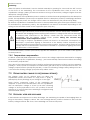
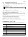
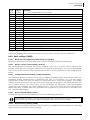
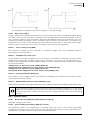
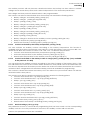
7.3
DEFAULT BATTERY CHARGE CYCLE (ORIGINAL SETTINGS)
The charge cycle set by default does not allow the
equalization phase and carries out only phase 1 (bulk), 2
(absorption) and 4 (floating) as per the figure to the right.
These factory parameter values of the VarioString are
adapted to open lead-acid batteries, with no equalization,
with an absorption voltage of 57,6V for 2h and a floating
voltage of 54.4V (equivalent to the “off” position of the DIP
switches n° 2, 3 and 4 when the VarioString is configured using
the internal DIP switch).
7.4
RECOVERY AFTER DEEP DISCHARGE
If the batteries are subjected to a deep discharge, the VarioString is capable of recharging them as
long as the battery voltage is above 18V. The recharge battery current is limited to 40A until the
battery voltage reaches 38V. Then, the VarioString can work at full power.
22
V 1.2.1
User manual
Studer Innotec SA
VarioString
8
CONFIGURING THE VARIOSTRING(S)
The VarioString can be configured simply, allowing charge behaviours that meet perfectly the
requirements of most lead-acid batteries. This configuration can be carried out using the DIP switches
(9) inside of the equipment to set the various configurations according to the position of each DIP
switch.
Before opening the VarioTrack, it is absolutely mandatory to disconnect all DC sources
(battery and PV) from the equipment to avoid any danger. After disconnection, it is
necessary to wait at least 5 minutes before opening the equipment, in order to guarantee
that dangerous internal residual voltages have disappeared.
It is also possible to make configurations specific to particular requirements of the system thanks to
the remote control RCC-02/03 described in the following chapter.
If an Xtender inverter/charger is interconnected (communication) to a VarioString, the
Xtender battery cycle will be imposed to the VarioString of the system. This function may
be disabled by parameter {14036}. If no Xtender is connected to the VarioString, the latter
uses its own setting. In the case of an installation with several VarioStrings, the battery
cycle is also automatically synchronized.
8.1
CONFIGURING THE EQUIPMENT BY MEANS OF THE INTERNAL DIP SWITCHES
Basic settings of the device can be entered manually with the aide of the DIP switch. This setting is
only possible if the parameter {14174} permits it. The following table provides an overview of the
functions associated with each position of the DIP switch.
Position
Function
1
Activation of DIP switch (of authorized by {14174})
2 to 4
Configuration of battery cycle
5 to 6
Reserved
7 to 8
Configuration of cabling of PV modules
Priority of DIP switch
The DIP switch parameter settings are prioritized over the parameter settings of the RCC.
Therefore, if the parameter {14174} authorizes the use of the DIP switch and the position 1
of the DIP switch is activated (in ON position), the DIP switch will have priority over the
parameter settings in the RCC. In this case, the following RCC parameter values will not be
taken into account:
Parameter related to the cabling of the PV modules {14002}
Parameters related to the battery cycle {14005}, {14009}, {14021}, {14017}, {14024},
{14008}, {14011}, {14023}
On the contrary, if the DIP switch is not activated (position 1 of the DIP switch is off or
parameter {14174} prohibits the utilisation of the DIP switch, the parameters of the RCC
related to cabling of the PV modules and the battery cycle will be utilized.
DIP switch 1 (first from the left) allows activating the settings defined by the DIP switch bank. This
activation will not be taken into account if the parameter {14174} does not allow it. When the settings
defined by the DIP switch bank are not activated, the default parameters (see list in chap.15) are
applied. These parameters can be modified by means of the remote control RCC-02/03.
If the default parameters (factory settings) are modified, the new values must be reported
in the parameter table in chap. 15 at the end of the manual which must remain on the
installation site at the disposal of the maintenance personnel.
User manual
V 1.2.1
23
Studer Innotec SA
VarioString
Pos. n°1
OFF
ON
Function
DIP switches not taken into account. Default parameters, or those set by the remote
control RCC-02/03 are active.
DIP switches are taken into account if authorized by {14174}
DIP switches no. 2, 3 and 4 allow the battery cycle to be modified as per the table below in order to
adapt it to the various types of most common lead-acid batteries. The following values are for a 48V
system.
Pos n°
Battery type
Floating
Absorption
Equalization (30min)
voltage
voltage/period
2
3
4
OFF OFF
OFF
Open
54.4V
57.6V / 2h
No
ON
OFF
OFF
Sealed w/short abs. 54.4V
57.6V / 1h
No
OFF ON
OFF
GEL
55.2V
56.8 / 2h
No
ON
ON
OFF
AGM
53.6V
57.2V / 2h
No
OFF OFF
ON
Sealed w/o abs.
54.4V
No
No
ON
OFF
ON
Open +
54.4V
57.6V / 2h
63.2 V - 1/ 20 days +
equalization
manual
OFF ON
ON
Open + manual
54.4V
57.6V / 2h
63.2 V + manual
equalization
ON
ON
ON
Open - reduced
53.6V
57.2V / 2h
63.2 V - 1/ 20 days +
voltage
manual
If a VarioString is interconnected (communication) to an Xtender inverter/charger, the
VarioString battery cycle will be automatically synchronized with the cycle of the Xtender in
the system. This function may be disabled by parameter {14036}.
When several VarioStrings are interconnected (communication) and linked to the same
battery, differences in production (power) are normal, especially in the following cases:
The units are in voltage regulation phase (absorption, equalization, floating), and in
this case the current distribution may be very uneven. This situation is normal and
has no influence on the system efficiency.
The equipment is in a bulk phase; in this case the difference is due to the
difference in size, orientation, cleanness, shade or any other situation that may
influence the production capacity of the solar generator. This situation may require
the generator to be checked in order to clear/remedy the possible fault.
DIP switches 7 and 8 allow the definition of the topology of the PV module connections, which can
be done in 3 different ways on the VarioString: independent (each string of PV modules connected
to one VarioString PV input), in series or in parallel. With the automatic position, the VarioString will
determine itself the connection topology. In this case, the VarioString will perform a cabling test when
it detects a voltage at both the PV inputs. Or, if a voltage at only 1 PV input is detected, the test
begins after 15 minutes. The automatic detection requires a certain power level to be available. In
the case of system commissioning at night or with a very low insolation, the test will be postponed
until the necessary conditions are present.
Pos n°
7
8
OFF OFF
ON OFF
OFF ON
ON ON
24
Connection mode of the
MPPT inputs
Automatic
MPPTs independents
MPPTs in series
MPPTs in parallel
V 1.2.1
User manual
Studer Innotec SA
VarioString
Connection of multiple VarioString
When several VarioStrings are interconnected by the communication bus and to the same battery,
if the DIP switch is used, it is imperative that the DIP switch settings are consistent among the
VarioString. The following table shows which DIP switch positions should be identical when more than
one VarioString is connected together.
Position
Function
Constraint if multiple VarioString
1
Activation of DIP switch (of authorized by {14174})
Identical for all
2 to 4
Configuration of battery cycle
Identical for all
5 to 6
Reserved
-
7 to 8
Configuration of cabling of PV modules
Can be different
Only the configuration of the cabling of the MPPT inputs can be different from one VarioString to
another. The battery charge cycle should be configured the same (one common battery for all the
VarioStrings). The battery charge cycle will therefore be automatically synchronized in all the devices.
Blockage of the DIP switch
Settings defined by the position of the DIP switches may be inhibited (disabled) with parameter
{14174} using the remote control RCC-02/03. The VarioString's operation will then be defined only by
the parameter values set by default or by the RCC remote control.
8.2
DISPLAYING THE EQUIPMENT STATUS USING THE REMOTE CONTROL RCC-02/03
8.2.1 Displaying the status of a single unit system
The VarioString screen allows displaying six values in real time. Four
values (a) can be chosen among many measured and calculated
values indicated in the table below and two show the status of the
auxiliary contacts (b) (these fields are visible even if an ARM-02 is not
present).
8.2.1.1
b
a
Choosing the displayed values
To choose which values to display, press the SET button to enter the first field which will appear with
a black background.
To modify the field content, use the SET button; then by using the arrows, consult the various
displayable values and select them as permanently displayable values in the related field by
validating with the SET button.
When no other value than the one initially displayed in the field is selected, ESC key validates the
initial choice.
The four fields can be scrolled and modified any time to display four of the values indicated in the
table below.
Info. no.
15000
15001
Name
Ubat
Ibat
Unit
Vdc
Adc
15002
Phase
Text
15003*
15004*
15005*
15006*
15007*
15008*
15009*
conf
Upv
Upv1
Upv2
Ipv
Ipv1
Ipv2
Text
Vdc
Vdc
Vdc
Adc
Adc
Adc
User manual
Description
Battery voltage
Battery current
Battery cycle phase (Bulk, Absorpt., Equalize, Floating, ---, ---,
R.float., Per.abs., ---, ---, ---, ---)
PV type of wiring (Unknown, Independ., Series, Parallel, Error)
PV voltage
PV1 voltage
PV2 voltage
PV current
PV1 current
PV2 current
V 1.2.1
25
Studer Innotec SA
VarioString
Info. no.
15010
15011*
15012*
Name
Ppv
Ppv1
Ppv2
Unit
kW
kW
kW
15013*
Mode
Text
15014*
Mod1
Text
15015*
Mod2
Text
15016
15017
15018*
15019*
15020
15021*
15022*
15023
15024*
15025*
15026
15027
15028*
15029*
15030*
15031*
15032
15033*
15034*
15035*
15036*
15037*
15038*
15039*
15040*
15041*
15042
Cd
Ed
Ed1
Ed2
kWhR
kWh1
kWh2
MWhT
MWh1
MWh2
Cd-1
EdEd1Ed2Sd
Sd-1
Tbat
Upmx
Upm1
Upm2
Ibmx
Ppmx
Ppm1
Ppm2
Ubmx
Ubmn
Tabs
Ah
kWh
kWh
kWh
kWh
kWh
kWh
MWh
MWh
MWh
Ah
kWh
kWh
kWh
h
h
°C
Vdc
Vdc
Vdc
Adc
kW
kW
kW
Vdc
Vdc
h
15049*
Err
Text
15050
Sync
Text
15051
Sync
Text
15052*
15053*
15108
EqIn
Bset
VS state
days
Vdc
Text
Description
PV power
PV1 power
PV2 power
PV operating mode (Night, Security, OFF, Charge, ChargeV,
Charge I, ChargeP, ChargeIpv, ChargeT, ---)
PV1 operating mode (Night, Security, OFF, Charge, ChargeV,
Charge I, ChargeP, ChargeIpv, ChargeT, ---)
PV2 operating mode (Night, Security, OFF, Charge, ChargeV,
Charge I, ChargeP, ChargeIpv, ChargeT, ---)
Production PV in (Ah) for the current day
Production PV in (kWh) for the current day
Production PV1 in (kWh) for the current day
Production PV2 in (kWh) for the current day
Produced PV energy resettable counter
Produced PV1 energy resettable counter
Produced PV2 energy resettable counter
Total PV produced energy
Total PV1 produced energy
Total PV2 produced energy
Production PV in (Ah) for the previous day
Production PV in (Wh) for the previous day
Production PV1 in (Wh) for the previous day
Production PV2 in (Wh) for the previous day
Number of irradiation hours for the current day
Number of irradiation hours for the previous day
Battery temperature
Max PV voltage for the current day
Max PV1 voltage for the current day
Max PV2 voltage for the current day
Max battery current of the current day
Max PV power for the current day
Max PV1 power for the current day
Max PV2 power for the current day
Max battery voltage for the current day
Min battery voltage for the current day
Time in absorption of the current day
Type of error (None, OverV_B, OverV_PV, OverV_PV1,
OverV_PV2, OverI_PV, OverI_PV1, OverI_PV2, GroundBat,
GroundPV, GroundPV1, GroundPV2, OverTemp, UnderV_B,
Cabling, Other)
Synchronized with Xtender battery cycle (No, Yes)
Synchronisation state (---, ---, ---, ---, XTslave, VTslave, ---, ---,
VTmaster, Autonom, VSslave, VSmaster)
Number of days before next equalization
Battery set point
State of the VarioString (Off, On)
*Some values can’t be displayed in the multi-unit display. They will be visible while going in the subscreen of the Multi-unit display, showing every unit individually.
26
V 1.2.1
User manual
Studer Innotec SA
VarioString
8.2.1.2
Displaying the triggering source of the auxiliary relays
To view the actual triggering source of the two auxiliary relays, press the SET button and use the
up/down arrows to navigate down to the two relay fields (b). Select one of the two relays and press
SET to view the information indicating the cause of the last relay activation (if the relay is presently
activated) or deactivation (if the relay is presently deactivated. The display also shows the logic
combination mode: AND or OR.
To exit the selected relay field, press ESC.
These information fields are visible even if the auxiliary relay ARM-02 see chapter 9.3), is not
connected.
8.2.2 Displaying the operating mode of the equipment (Info n° 15013,15014,15015)
Night: the solar generator voltage (or luminous intensity) is not enough to start the equipment. When
this indication appears during the day, it means a generator fault (wiring).
Charge: the charger operates normally at the maximum power point of the solar generator.
Charge U: the VarioString operates in voltage regulation (absorption, equalization, or floating). In this
status, it is normal to see a current lower than the maximum possible.
Charge I: the VarioString has reached the maximum allowed current fixed by the parameter {14001}
“battery charge current”. In this status, the power of the generator is limited to a lower value then
the maximum possible.
Charge T: the maximum permissible temperature of the VarioString is reached and the power is
limited by the temperature. This status is not a problem but may highlight that the system
performances could be enhanced by reducing ambient temperature.
Charge P: the max power of the VarioString is reached (7000W). This mode is also shown if one of the
two MPPT inputs reaches its maximum power in independent mode (3500W).
Charge Ipv: the max current is reached for one of the two MPPT inputs (13A).
Security: the equipment turns off due to a fault normally indicated by a message on the RCC or by
the “error” indicator (3) on the equipment.
Off: the equipment is manually turned off by the operator or using a remote control.
8.2.3 Displaying security errors (Info n° 15049)
When a security error occurs, the device will stop functioning. A short text, limited to 8 characters, will
appear on the display indicating which kind of error it is.
Text
None
GroundBat
GroundPV
GroundPV1
GroundPV2
OverTemp
OverV_B
UnderV_B
OverI_PV
OverI_PV1
OverI_PV2
OverV_PV
OverV_PV1
User manual
Description
No error. The unit is fully functional
The battery grounding mode is different from that chosen in the parameter settings
(chap. 4.4.1.)
The PV grounding in parallel or series mode is different from that chosen in the
parameter settings (chap. 4.4.1).
The grounding of the MPPT input PV1 is different from that chosen in the parameter
settings (chap. 4.4.1).
The grounding of the MPPT input PV2 is different from that chosen in the parameter
settings (chap. 4.4.1).
An abnormal high temperature is detected (Alarm 014).
A battery voltage higher than 68V has been detected (alarm 20).
The battery voltage is too low to start the charger.
A PV voltage over 600V has been detected in parallel mode, or over 900V in series
mode (alarm 82).
A PV voltage over 600V has been detected in the MPPT input PV1.
A PV voltage over 600V has been detected in the MPPT input PV2.
The max input current has been exceeded (series or parallel cabling).
The max input current has been exceeded in PV1.
V 1.2.1
27
Studer Innotec SA
VarioString
Text
OverV_PV2
Cabling
Description
The max input current has been exceeded in PV2.
A cabling error has been detected on the PV inputs or the cabling does not
correspond to the selected mode (chap 4.4.1).
8.2.4 Displaying the values of a multi-unit system
When several VarioString units are
connected to the remote
control RCC-02/03, the screen
VarioString
MULTI
appears,
displaying
the
consolidated
values for all the connected
equipment. The displayed values
can be selected as per the same procedure described in chap. 8.2.1.1. Moreover, the units can be
viewed one by one by using the arrows up/down after the SET button (2x) when the VarioString image
is with a black background.
8.2.5 Displaying messages and event history
The message system is the same as for an Xtender inverter/charger or a VarioTrack MPPT solar charge
controller and the alarm messages/information are stored and displayed in the same list. See the
RCC remote control user manual.
8.2.5.1
Message list
Alarm (000): low battery voltage: the battery voltage is lower than 40V for more than 30 seconds. The
VarioString continues to work until the battery voltage falls below 18V.
Message (012): management of the BTS (temperature sensor): this indication is given only if the sensor
is connected to the VarioString when it is energized.
Switch off (014): EL Over-temperature: the warmest point inside the equipment has exceeded the
allowed highest temperature. The equipment stops operating. It starts again when the temperature
drops back to a normal value.
Switch off (020): battery overvoltage: the battery voltage is higher than 68V. The VarioString turns off.
It starts again when the voltage returns to a normal value.
Alarm (081): PV earth fault: the battery earthing does not (anymore) match the selection made by
parameters {14040}, {14041} and {14042} which establishes the type of earthing to be checked.
Alarm (082): PV overvoltage: the solar generator has a voltage higher than 600V (parallel or
independent connection) or higher that 900V (series connection).
Message (083), (170), (171): no solar production for 48h: no PV voltage has been detected for 48H.
The PV generator has probably been disconnected. Check the protection devices (fuse or circuit
breaker) and/or check the wiring.
Message (084): equalization carried out: indicates the end of the equalization cycle.
8.3
CONFIGURING THE VARIOSTRING USING THE REMOTE CONTROL RCC-02/03
Many parameters are stored in the VarioString internal memory. When a parameter is modified using the
remote control RCC-02/03 (hereafter referred to as RCC), it is sent to the VarioString and stored permanently.
If the RCC is removed from the system, this parameter continues to be used by the VarioString with
this modified value. If the VarioString is disconnected and then connected again, the new value can
be retrieved from the memory. This allows for example to pre-program a VarioString at the workshop
and to supply it to a customer, ready for his specific application.
If the settings made using the DIP switches are disabled, either because the Pos 1=off or because the
parameter disabling the DIP switches {14174} = yes, the VarioString uses its stored values. The parameters'
factory values of the equipment are equivalent to the values set when all the DIP switches are in “OFF”
position, i.e. adapted to an open battery, without equalization, with an absorption voltage of 57,6V
during 2h and a floating voltage of 54,4V.
28
V 1.2.1
User manual
Studer Innotec SA
VarioString
The parameter values can be modified using the RCC and are stored and applied by the VarioString.
When the remote control RCC is connected to the VarioString by the communication bus
it is possible that the software versions are not compatible. It is highly recommended to
update the software of all components in the system in order to guarantee all
functionalities. Therefore, before starting the setup of the device, download the latest
software version from our website: www.studer-innotec.com on an SD card. Follow the
instructions in the RCC manual for a successful installation.
8.3.1 The real time clock
The VarioString features a real time clock that allows among others to have a correct date and hour
for the RCC records. This clock must be set using the remote control RCC-02/03. Thanks to an internal
battery, this setting is retained even when the equipment is disconnected from its voltage source
(battery or PV).
8.4
DESCRIPTION OF THE VARIOSTRING PARAMETERS
The parameters of the VarioString can be modified in the menu “VarioString MPPT setting" of the RCC
remote control.
This menu allows accessing the following 4 under-menus:
BASIC SETTINGS: where the most common parameters to be set when commissioning are found.
BATTERY MANAGEMENT AND CYCLE: where all the parameters can be set, defining in detail the
battery cycle during all its phases.
SYSTEM MENU: gathering a few parameters that are not directly related to the battery cycle, such as
backing up and restoring the system, resetting, monitoring setting, etc.
AUXILIARY CONTACTS: where the parameters related to the auxiliary relays (optional accessory ARM02) can be set.
8.4.1 Convention
Functions and values of the parameters mentioned in this manual are described in this chapter. Each
parameter is defined by a short description, a number {xxxxx} followed by its value and unit by default
(xxxxx). The type of parameter (menu, signal) replaces the value between brackets when this latter
does not exist. The RCC menus are also identified by a name and a number {xxxxx} that can be
found, as per the parameter number, on the top right-hand corner of the RCC screen.
8.4.2 Parameter access level
All the parameters described hereafter are accessible through 2 different access levels. In factory
configuration, only a few of them are accessible through the “basic menu”.
To access all the other menus and parameters, the RCC must be configured at the “Expert” level
following the procedure given in the RCC manual, chapter “User level”.
The parameters in grey are accessible only by qualified personnel.
User manual
V 1.2.1
29
Studer Innotec SA
VarioString
8.4.3 Organisation of the VarioString configuration menu
Level
Basic
Expert
Expert
Basic
Basic
Inst.
Expert
Basic
Expert
Expert
Expert
Basic
Expert
Expert
Expert
Basic
Expert
Expert
Expert
Expert
Expert
Basic
Expert
Basic
Expert
Expert
Expert
Expert
Expert
Expert
Expert
Expert
Expert
Expert
User ref.
14000
14174
14001
14002
14067
14068
14003
14036
14001
14035
14004
14005
14006
14007
14008
14009
14010
14011
14012
14013
14016
14017
14018
14021
14020
14022
14023
14024
14025
14026
14019
14027
14028
14029
Expert
14030
Time period under voltage level 1 to start a new cycle
Expert
14031
Voltage level 2 to start a new cycle
Expert
14032
Time period under voltage level 2 to start a new cycle
Expert
Expert
Basic
Expert
Expert
Expert
Expert
Expert
Expert
Expert
14033
14034
14037
14174
14040
14041
14175
14042
14180
14043
30
Parameter
BASIC SETTINGS
Block manual programming (dip-switch)
Battery charge current
Configuration of PV modules
Restore default settings
Restore factory settings
BATTERY MANAGEMENT AND CYCLE
Synchronisation battery cycle with Xtender
Battery charge current
Temperature compensation
Floating phase
Floating voltage
Force phase of floating
Absorption phase
Absorption phase allowed
Absorption voltage
Force absorption phase
Absorption duration
End of absorption triggered by the current
Current threshold to end absorption phase
Equalization phase
Equalization allowed
Force equalization
Equalization voltage
Equalization current
Equalization duration
Equalization with fixed interval
Days between equalizations
End of equalization triggered by the current
Current threshold to end equalization phase
Equalization before absorption phase
New cycle
Force a new cycle
Voltage level 1 to start a new cycle
Cycling restricted
Minimal delay between cycles
SYSTEM
Block manual programming (dip-switch)
Type of battery grounding
Type of PV grounding
Type of PV1 grounding
Type of PV2 grounding
Type of MPPT algorithm
Type of MPP tracking algorithm PV
V 1.2.1
User manual
Studer Innotec SA
VarioString
Level
Expert
Expert
Expert
Expert
Expert
Expert
Expert
Expert
Expert
Inst.
Inst.
Inst.
Inst.
Basic
Inst.
Inst.
Expert
Expert
Expert
8.4.3.1
User ref.
14044
14179
14045
14176
14177
14178
14046
14047
14048
14190
14182
14051
14052
14067
14068
14069
14038
14039
14059
Parameter
PV voltage fixed (for PV in series)
PV voltage fixed (for PV in //)
Ratio of PV open circuit voltage
Type of MPP tracking algorithm PV1
PV1 voltage fixed
Ratio of PV1 open circuit voltage
Type of MPP tracking algorithm PV2
PV2 voltage fixed
Ratio of PV2 open circuit voltage
PV wiring type erased from memory
Reset PV energy meter
Reset daily solar production meters
Reset daily min-max
Restore default settings
Restore factory settings
Parameters saved in flash memory
ON of the VarioString
OFF of the VarioString
Reset of all VarioString
Auxiliary relay parameters
A list of the auxiliary relay parameters can be found at the end of this manual in chapter 15.
8.4.4 Basic settings {14000}
8.4.4.1
Block manual programming (DIP switch) {14174} (No)
Blocks the operating mode chosen by means of the DIP switches inside the VarioString.
8.4.4.2
Battery charge current {14001} (120 Adc)
The VarioString tries to maximize the battery charging current up to its rated current; however, it is
possible to limit this current using this parameter for small capacity batteries. The current appropriate
to the battery is reported in its technical data. The value set by this parameter is used during the bulk
phase.
8.4.4.3
Configuration of PV modules {14002} (Automatic)
This parameter allows the selection of the type of cabling of the MPPT inputs. In automatic mode, the
VarioString makes measurements to determine the type of connection. You can also select
independent mode if you have two distinct PV strings that are not connected together. The parallel
cabling mode is reserved for the case when your PV string(s) are brought to the VarioString with one
set of cables and the two MPPT inputs on the VarioString are physically connected (cabling
accessories are available). The series cabling mode is used for PV strings with max voltage levels
higher than 600V; in which case the PV generator is connected to PV2- and PV1+, and PV2+ and
PV1- are physically bridged.
8.4.4.4
Restore default settings {14067}
Sending this signal restores the original values of the VarioString parameters.
If the installer has made some adjustments during the commissioning of the installation, this
function does not restore the factory settings but those made by the installer.
8.4.4.5
Restore factory settings {14068}
This parameter is accessible only when the RCC-02/03 is in installer level and allows the VarioString
parameters to be restored to factory settings.
User manual
V 1.2.1
31
Studer Innotec SA
VarioString
8.4.5 Battery management and cycle {14003}
The VarioString battery charger is designed to ensure a battery
charge as complete as possible. The charge process,
described in detail in chapter 7.2 is managed in 4 successive
phases of which only 3 are activated by default. Thus the
VarioString will carry out only phases 1 (bulk), 2 (absorption)
and 4 (floating) according to a charge profile as per the figure
to the right which represents the basic cycle. This basic cycle
takes place automatically.
The charge curve obtained this way depends on a whole series of parameters that may be freely
modified in order to get a charge profile that meets at best the requirements set by the manufacturer
or the user.
If the BTS-01 temperature sensor (or the BSP, battery status processor) is used, the voltage regulation
thresholds of the battery are corrected in real time according to the battery temperature. The value
of this compensation in mV/°C/cell for a reference temperature of 25°C is set by parameter {14035}
to -3mV/°C/cell.
The battery setting is carried out under the responsibility of the operator. An incorrect setting
that does not meet the battery charging methods recommended by the manufacturer
may be dangerous and/or considerably reduce the battery service life. If the factory
settings are modified, the new values must be entered in the parameter table at the end of
this manual.
8.4.5.1
Synchronisation battery cycle with Xtender {14036} (yes)
When a Studer inverter of the range Xtender is used in the system, it can transfer to the VarioTrack its
battery charge setting so that they can operate together in an optimum way. Synchronization allows
a coherent operation of multiple units which participate to the battery charging and avoids multiple
successive equalizations triggered by each charger.
When this parameter {14036} is activated, all other parameter involved in the battery cycle
are hidden and not accessible. In this case, only the maximum charging current is
adjustable.
8.4.5.2
Battery charge current {14001} (120 Adc)
See Basic Settings, chap. 8.4.4.2.
8.4.5.3
Temperature compensation {14035} (-3mV/°C/cell)
If a BTS-01 or BSP temperature sensor is used, the voltage adjustment thresholds for charging the
battery (absorption, equalization, floating…) are automatically corrected in real time according to
the battery temperature. The value of this compensation in mV/°C/cell for a reference temperature
of 25°C is set by parameter {14035} to -3mV/°C/cell. For example: for a 48V battery (24 cells of 2V) at
a temperature of 30°C, the voltage compensation is: (30-25)*24*(-3/1000) = -0.36V. For a floating
voltage value {14005} set to 54.4 V the effective floating voltage (compensated) will be 54.0 V.
8.4.5.4
8.4.5.4.1
Floating phase {14004}
Floating voltage {14005} (54.4 Vdc)
Determines the voltage applied when the battery is fully charged. This voltage prevents selfdischarge and keeps the battery to its optimum charge level.
8.4.5.4.2
Force phase of floating {14006}
This parameter may be used to force a battery cycle in progress to assume the final values of the
floating voltage phase. If the battery voltage level is higher, the charger momentarily switches out
until the new target voltage is reached.
8.4.5.5
Absorption phase {14007}
During this phase, the battery accumulates the last percentages of power to be stored. This phase
takes place at a constant voltage. Over the course of this phase, the necessary current diminishes
32
V 1.2.1
User manual
Studer Innotec SA
VarioString
progressively. Therefore, the VarioString does not work at the optimal point of the PV generator
because all the available PV power is not required.
8.4.5.5.1
Absorption phase allowed {14008} (yes)
This parameter determines whether the absorption phase is carried out or not. When this phase is
disabled, the charger goes directly to the following authorized phase (equalization, but most often
a floating phase).
8.4.5.5.2
Absorption voltage {14009} (57.6 Vdc)
Defines the applied voltage during absorption phase.
8.4.5.5.3
Force absorption phase {14010} (signal)
This signal starts again an absorption phase from the floating phase. The charge indicator (2) flashes
2x indicating that the equalization phase is on-going.
8.4.5.5.4
Absorption duration {14011} (120 min)
Use this parameter to set the absorption duration. The absorption phase starts once the set voltage
{14009} is reached. When the time is over (see chap. 7.2.2), the charger goes automatically to the
following authorized phase.
8.4.5.5.5
End of the absorption triggered by the current {14012} (no)
The absorption phase can be interrupted when the battery charging current goes under a certain
threshold, at which point the charger automatically passes to the next authorized phase. This can be
used in order to shorten the period under which a high voltage is applied and thus reduce water
consumption.
8.4.5.5.6
Current threshold to end absorption phase {14013} (10 Vdc)
Progressively, during the absorption phase, the charging current decreases naturally. If the bulk
phase has been carried out with a current appropriate for the battery, it is not necessary to wait for
a certain period to finish charging. The absorption phase can be interrupted if the battery charge
current falls below a certain level.
This parameter sets the current under which the absorption phase is considered finished. When the
charger current goes below this value, the next phase (most often the floating phase) starts. If the
production of the PV generator is insufficient to keep the voltage, this current is not taken into
account and the absorption phase goes on.
8.4.5.6
Equalization phase {14016}
Some types of battery need equalization in order to avoid the stratification of the water and acid
they contain. Use the parameters hereafter to set the operating conditions of this charging phase as
described in chap. 7.2.4.
During an equalization phase, an emission of a highly explosive gas occurs
(hydrogen/oxygen). Follow carefully all the instructions of the battery manufacturer
regarding this phase. In any case, make sure that the battery room is adequately
ventilated. Equalization reduces the battery water level: check it regularly.
8.4.5.6.1
Equalization allowed {14017} (no)
Determines whether the equalization phase (triggered manually or automatically) is allowed or not.
8.4.5.6.2
Force equalization {14018}
Use this parameter to manually start the equalization phase. It is only possible to force an equalization
phase when it is authorized by {14017}.
User manual
V 1.2.1
33
Studer Innotec SA
VarioString
8.4.5.6.3
Equalization voltage {14021} (62.4 Vdc)
This parameter determines the maximum voltage during the equalization phase.
This voltage is corrected by the temperature compensation factor {14035} if a temperature
sensor (BTS-01 or BSP) is installed in the system.
Once equalization phase is initiated, disabling the phase does not stop the equalization.
To stop the equalization, force the transition into floating {10006}, absorption {10010} or a
new cycle {10029}. It is also possible to interrupt the equalization by pressing the « SET »
button for more than 2 seconds (procedure described in chap. 6.1.
8.4.5.6.4
Equalization current {14020} (80 Adc)
The equalization phase can be carried out with a limited current that can be adjusted using this
parameter. In any case, the current does not exceed the bulk current {14001}. As a rule, the limited
charging current is used only if the equalization is started at the end of the absorption phase.
8.4.5.6.5
Equalization duration {14022} (30 min)
This parameter determines the equalization period. The equalization phase starts as soon as the set
battery voltage exceeds the absorption voltage. When the period has elapsed, the charger goes
automatically to the following authorized phase. If the voltage cannot be kept (no sunshine,
clouds...), the countdown is paused.
8.4.5.6.6
Equalization with fixed interval {14023} (yes)
When this parameter is activated (yes), the battery charge cycle with an active equalization phase
starts at the interval specified by the following parameter {14025}.
8.4.5.6.7
Days between equalizations {14024} (26 days)
This parameter determines the number of days in between the equalizations. This counter is reset to
zero when the equalization is activated manually.
In the case of incomplete charging cycles (for example when charging with solar
generators), this function is useful also to limit the repetition of the equalization cycles.
When the number of days is reached, a new cycle is not initiated automatically. The
equalization will take place during the following charge cycle.
8.4.5.6.8
End of the equalization triggered by the current {14025} (no)
Progressively, during the equalization phase, the charging current decreases naturally. If the bulk
phase has been carried out with a current appropriate for the battery, it is not necessary to wait for
a certain period to finish charging. The equalization phase can be interrupted when the battery
charging current goes under a certain threshold. This can be used in order to reduce the equalization
duration and the electrolysis phenomenon related to it.
8.4.5.6.9
Current threshold to end equalization phase {14026} (10 Adc)
This parameter determines at which current the equalization phase is considered finished. The next
phase starts, when the charger current goes below this value.
8.4.5.6.10 Equalization before absorption phase {14019} (yes)
This parameter determines if during the charge cycle the equalization will take place before or after
the absorption phase. By default, the equalization phase is carried out before the absorption phase.
34
V 1.2.1
User manual
Studer Innotec SA
VarioString
A= equalization voltage, B= absorption voltage, C= floating voltage
8.4.5.7
New cycle {14027}
Usually, batteries are charged during the day via the PV generator then partially discharged during
the night by the user. The next day, a charge cycle starts again (bulk-absorption-floating). To start a
new complete charge cycle the battery should be discharged below the conditions set by the
parameters {14029} to {14034}. If these conditions have not been met because, for example, the
installation has no users, a new absorption phase will not be necessary as this would lead to slight
battery water consumption. In this case, the charge cycle is kept in floating phase.
8.4.5.7.1
Force a new cycle {14028}
This parameter enables to force manually a complete charge cycle. The VarioString switches
immediately to the bulk phase.
8.4.5.7.2
Conditions for a new cycle
A new battery cycle will be triggered if one or the other 2 conditions, defined by a period of time
during which the battery voltage is lower than a threshold, is met. These 2 voltages related to 2
durations are configurable. Usually a higher voltage is used for a longer duration and a lower voltage
for a shorter duration.
Voltage level 1 to start a new cycle {14029} (48.8 Vdc)
Time period under voltage level 1 to start a new cycle {14030} (30 min)
Voltage level 2 to start a new cycle {14031} (47.2 Vdc)
Time period under voltage level 2 to start a new cycle {14032} (2 sec)
8.4.5.7.3
Cycling restricted {14033} (yes)
The repetition of the charge cycles can be limited establishing the minimum time between each
cycle using parameter {14034}.
8.4.5.7.4
Minimal delay between cycles {14034} (1 hour)
Determines the minimum interval (time) between each cycle when parameter {14033} activates this function.
If the parameter {14033} is activated and the interval parameter {14034} is set to 24h, there
will be only one charge cycle per day. In this case, if the conditions are met for a new cycle,
it will not take place until the next day and the charger will keep the battery at floating
voltage.
8.4.6 System {14037}
8.4.6.1
Block manual programming (DIP switch) {14174} (no)
See Basic Settings chap. 8.4.4.1.
8.4.6.2
Type of battery grounding {14040} (no control)
This parameter allows the VarioString to constantly verify the state of the battery grounding
connection, if desired. In the event of an error, the VarioString stops until the battery grounding is reestablished. It is possible to ground either of the battery terminals.
User manual
V 1.2.1
35
Studer Innotec SA
VarioString
8.4.6.3
Type of PV grounding {14041} (no control)
This parameter allows the VarioString to constantly verify the state of the PV grounding connection
during its use in series or parallel mode. In the event of an error, the VarioString stops until the PV
grounding is re-established. It is possible to ground either of the PV terminals.
8.4.6.4
Type of PV1 grounding {14175} (no control), Type of PV2 grounding {14042} (no control)
The same as the preceding parameter, but for the MPPT inputs PV1 and PV2 in independent mode.
8.4.6.4.1
Type of MPP tracking {14043} (P&O)
This parameter allows setting the type of algorithm used by the VarioString to establish its operating
point in series or parallel cabling mode.
P&O: Maximum Power Point (MPP) search algorithm. This algorithm is fully automatic and searches
the MPP of your system.
OC ratio: With this mode, the VarioString makes an open circuit voltage measurement once every 5
minutes and fixes the working voltage at a point proportional to the measurement. The measurement
lasts 2 seconds.
Ratio of PV open circuit voltage {14045} (0.7)
This parameter fixes the operating point according to the measured open circuit voltage. The
measured open circuit voltage is multiplied by this ratio to calculate the operating point. (ex.: the
measured open circuit voltage is 500V, Ratio 0.7, the operating point will be 500x0.7=350V).
Upv fixed: with this mode the VarioString fixes the PV operating voltage and it does not vary.
PV voltage fixed (for PV in series) {14044} (700 Vdc)
PV voltage fixed (for PV in parallel) {14179} (500 Vdc)
These parameters allow to set the voltage value at which you wish to set the operating point.
8.4.6.4.2
Type of MPP tracking algorithm PV1 {14176} (P&O) and Type of MPP tracking algorithm
PV2 {14046} (P&O)
Same as the preceding parameter but for when the PV1 and PV2 inputs are used independently.
8.4.6.5
PV wiring type erased from memory {14190}
This parameter resets the type of PV wiring detected by the VarioString.
8.4.6.6
INSTALLER: Reset PV energy meter {14182}
This parameter allows you to reset the PV energy meter to zero. This could be useful if you wish to
measure the energy produced over a given time interval.
8.4.6.7
INSTALLER: Reset daily solar production meters {14051} and
8.4.6.8
INSTALLER: Reset daily min-max {14052}
These parameters allow you to reset to zero the different corresponding daily meters. This could be
useful if you wish to know these values precisely over a specific period of time.
8.4.6.9
Restore default settings {14067}
See basic parameters, chap. 8.4.4.4.
8.4.6.10 INSTALLER: Restore factory settings {14068}
See basic parameters, chap. 8.4.4.5
8.4.6.11 INSTALLER - Parameters saved in flash memory {14069} (yes)
This parameter allows you to determine if the parameters modified within your system should be
saved or not to the flash memory. With the objective to increase the useful life of the flash memory
in the case of repeated writing to it, this parameter should be deactivated (no), for example, if the
VarioString is piloted by an external control and supervision system, SCADA.
36
V 1.2.1
User manual
Studer Innotec SA
VarioString
8.4.6.12 ON of the VarioString {14038}
This parameter allows to turn on all the VarioString in the system.
8.4.6.13 OFF of the VarioString {14039}
This parameter allows to turn off all the VarioString in the system.
8.4.6.14 Reset of all VarioString {14059}
This parameter allows to restart all the VarioString in the system.
8.4.7 Auxiliary contacts 1 {14070} and 2 {14122}
When connected to the ARM-02 module (see chap. 9.3 – p. 42), the solar charge controller
VarioString has two additional external auxiliary relays with potential-free dry reversing contacts.
These two relays make it possible to realize multiple functions with appropriate cabling and simple
programming.
The programming of each
contact
is
made
independently. The auxiliary
contacts are activated and
deactivated with a 2 second
delay to avoid too frequent
switching.
The auxiliary contacts react
to different types of signals,
graphically illustrated below.
Basic events that activate
the contacts are:
Simple events
Scheduled events
Levels
In the following descriptions,
each parameter has two
reference numbers. The
reference number on the left
refers to the auxiliary contact
1 and the reference number
on the right refers to the
auxiliary
contact
2.
({reference auxiliary contact 1} {reference auxiliary contact 2}).
8.4.7.1
Operating mode {14071} {14123} (automatic)
The auxiliary contact can be controlled in 4 different ways:
Manual ON: in this mode, the contact is permanently activated "ON" whatever the external
conditions or programming.
Manual OFF: in this mode, the contact is permanently deactivated "OFF" whatever the external
conditions or programming.
Automatic: in this mode the auxiliary contact is activated according to the conditions and restrictions
of its programming.
Reversed automatic: in this mode, the conditions and restrictions define the deactivation of the relay.
8.4.7.2
Combination of the events for the auxiliary contact {14072} {14124} (first active (OR))
This parameter defines how various events intended to activate the auxiliary contact are combined.
The contact can be activated either by a single event (OR function) or by all events being fulfilled
at the same time (AND function).
8.4.7.3
Contacts activated by an event {14077} {14129}
Different states and events within the installation can be used to activate the auxiliary contacts. The
events can be combined with each other to create complex functions.
User manual
V 1.2.1
37
Studer Innotec SA
VarioString
8.4.7.3.1
Contacts activated in night mode {14073} {14125}
The auxiliary contact can be activated with the function "night mode". When the “night mode” is
activated and the activation delay is up, the auxiliary contacts will be active for a predefined time
period. If the activation time is set to zero, the auxiliary contact will remain permanently activated
until the end of the night mode.
Activated in night mode {14074} {14126} (no)
Delay of activation after entering night mode {14075} {14127} (1 min)
Activation time for the auxiliary relay in night mode {14076} {14128} (1 min)
8.4.7.3.2
VarioString is ON {14188} {14189} (no)
The contact is activated if the VarioString is switched ON.
8.4.7.3.3
VarioString is OFF {14078} {14130} (no)
The contact is activated if the VarioString is switched OFF.
8.4.7.3.4
Battery undervoltage {14079} {14131} (no)
The contact is activated in the event of battery undervoltage.
8.4.7.3.5
Battery overvoltage {14080} {14132} (no)
The contact is activated in the event of battery overvoltage.
8.4.7.3.6
Earth fault {14081} {14133} (no)
The contact is activated in the event of an earth fault.
8.4.7.3.7
PV error (48h without charge) {14082} {14134} (no)
The contact is activated in case the battery has not been charged in the last 48 hours.
8.4.7.3.8
Overtemperature {14083} {14135} (no)
The contact is activated in the event of over temperature of the device.
8.4.7.3.9
Bulk charge phase {14084} {14136} (no)
The auxiliary contact is activated if the battery is charging in the bulk phase.
8.4.7.3.10 Absorption phase {14085} {14137} (no)
The auxiliary contact is activated if the battery is charging in the absorption phase.
8.4.7.3.11 Equalization phase {14086} {14138} (no)
The auxiliary contact is activated if the battery is charging in the equalization phase.
8.4.7.3.12 Floating phase {14087} {14139} (no)
The auxiliary contact is activated if the battery is charging in the floating phase.
8.4.7.3.13 Reduced floating phase {14088} {14140} (no) and
8.4.7.3.14 Periodic absorption phase {14089} {14141} (no)
You can activate the auxiliary contacts on the reduced floating phase and periodic absorption
phase in presence of an Xtender and synchronised with the battery cycle.
8.4.7.4
Contacts activated by the battery voltage {14090} {14142}
These parameters activate the auxiliary contacts if the voltage drops below a pre-defined voltage
level during a set time period. It is possible to define three voltages linked with three time periods to
activate the auxiliary contact.
38
V 1.2.1
User manual
Studer Innotec SA
VarioString
The auxiliary contact will only become deactivated when the battery has risen above a certain
voltage and a certain time period, both values independent of the activation parameters.
This voltage and time period for deactivation is also programmable.
The contact can also be deactivated when the battery has reached the floating phase.
Battery voltage 1 activated {14091} {14143} (no)
Battery voltage 1 {14092} {14144} (46.8 Vdc)
Delay 1 {14093} {14145} (1 min)
Battery voltage 2 activated {14094} {14146} (no)
Battery voltage 2 {14095} {14147} (47.8 Vdc)
Delay 2 {14096} {14148} (10 min)
Battery voltage 3 activated {14097} {14149} (no)
Battery voltage 3 {14098} {14150} (48.5 Vdc)
Delay 3 {14099} {14141} (60 min)
Battery voltage to deactivate the auxiliary contact {14100} {14152} (54 Vdc)
Delay to deactivate {14101} {14153} (60 min)
Deactivate if battery in floating phase {14102} {14154} (no)
8.4.7.5
Contacts activated by the battery temperature {14103} {14155}
You can activate an auxiliary contact according to the battery temperature. This function is
available with the battery temperature sensor BTS-01 or with the battery status processor BSP. Two
distinct levels allow the contact to switch “ON” and “OFF” at different temperatures.
Contact activated with the battery temperature {14104} {14156} (no)
Activation temperature for the auxiliary contact {14105} {14157} (3°C)
Deactivation temperature for the auxiliary contact {14106} {14158} (5°C)
8.4.7.6
Contacts activated on the battery's state of charge (SOC) {14108} {14160} (only available
in the presence of a BSP)
You can activate the auxiliary contacts according to the state of charge of the battery (SOC). If the
SOC falls below the set level, the contact will be activated. A time period can be associated with the
SOC level to stipulate that the battery must be below the set level a certain time before the contact is
activated. Three voltage limits with associated delay periods are available for programming.
The contact is deactivated when the battery’s SOC rise above the pre-set level which can also be
associated with a time period.
The contact may also be deactivated when the battery reaches the floating phase.
Contact activated at SOC 1 {14109} {14161} (no)
Contact activated below SOC 1 {14110} {14162} (50% SOC)
Delay 1 {14111} {14163} (12 h)
Contact activated at SOC 2 {14112} {14164} (no)
Contact activated below SOC 2 {14113} {14165} (30%)
Delay 2 {14114} {14166} (0.2 h)
Contact activated at SOC 3 {14115} {14167} (no)
Contact activated below SOC 3 {14116} {14168} (20%)
Delay 3 {14117} {14169} (0 h)
Contact deactivated below SOC {14118} {14170} (90% SOC)
Deactivation time {14119} {14171} (0.2 h)
Deactivation if the battery is in floating phase {14120} {14172} (no)
8.4.7.7
Reset all settings {14121} {14173}
This parameter is used to cancel all the programming that has been made on the corresponding
auxiliary contact. Once this parameter is executed, the auxiliary contact will not activate.
Caution, this parameter cannot be cancelled.
User manual
V 1.2.1
39
Studer Innotec SA
VarioString
Use this parameter before programming any functions in the auxiliary contact. This way,
you are sure that you begin programming without any previous programming that will
activate the contact involuntarily.
9
9.1
ACCESSORIES
REMOTE CONTROL AND PROGRAMMING CENTRE RCC-02/03
This accessory is an important complement to the VarioString. It can be connected via one of the
two communication connectors "Com. Bus" (7) (see chap. 4.1 Elements of the cable compartment)
thanks to the cable supplied with the remote control.
When the remote control RCC-02/03 is connected to another compatible device
(Xtender, VarioString, BSP, Xcom or other) with the same communication bus it is possible
that the software versions are not compatible. It is highly recommended to make a
software update of all components in the system in order to guarantee all functionalities.
Therefore, before starting the setup of the device, download the latest software version
from our website: www.studer-innotec.com on an SD card. Follow the instructions in the
RCC manual for a successful installation.
These connectors must be used only to connect a compatible Xtender accessory.
The remote control RCC-02/03 is compatible with the following equipment:
VarioTrack MPPT solar charge controller
VarioString MPPT solar charge controller
Xtender inverter/chargers
When it is connected to at least one of these three devices, it also allows interacting with the other
peripherals of an Xtender system, i.e.:
Battery Status Processor BSP-500/BSP1200
RS 232 communication interface: Xcom-232i
Communication sets: Xcom-LAN/-GSM
It allows the following functionalities for all the connected and compatible equipment:
Setting the various operating parameters for the connected equipment.
Displaying the operating synoptic for each part of the equipment.
Displaying several operating quantities measured or calculated (Current/Voltage/Power,
etc.) for each apparatus.
Updating the software or implementing tailored software.
Backing up/restoring system parameters (configuration).
Loading a parameter file (configuration).
Storing error message history for each device.
Recording VarioString(s) data and other information essential for the system (see chapter
“Data recorder” p. 23 in the RCC manual).
40
V 1.2.1
User manual
Studer Innotec SA
VarioString
RCC-02
RCC-03
Functionalities of the RCC-02 and RCC-03 units are equivalent. They differ only in their external
aspect. The RCC-02 is designed for wall mounting whereas the RCC-03 is designed for board
mounting.
Model RCC-03 must be removed from the board to access the SD card slot (during updating, for
example).
Reference number Studer Innotec
Dimensions H x L x l [mm]
RCC-02
170 x 168 x 43.5
RCC-03
130 x 120 x 42.2
Both remote control models are supplied with a 2m cable.
Cables of specific lengths (5m, 20m and 50m) can be ordered.
Item reference: CAB-RJ45-8-xx. The length in metres is specified by xx.
It is possible to connect up to 2 RCC or Xcom to a single VarioString, and up to 3 RCC or Xcom to a
system with several VarioString or Xtender units.
The termination switch of the communication bus "Com. Bus" (8) remains in position T
(terminated) except when both connectors (7) are used. In this case and only in this case,
the switch must be placed in the O (open) position.
9.2
TEMPERATURE SENSOR BTS-01
The operating voltages for lead batteries vary depending on the temperature.
A temperature sensor is optionally available to correct the battery voltage
and guarantee an optimum charge for whatever battery temperature. The
correction factor given by the temperature sensor is set by parameter {14035}.
A single temperature sensor connected to one of the devices is enough in a
system containing several VarioString connected to the same battery bank
(multi-system).
Reference no. for the temperature sensor (including a 5m cable): BTS-01.
Dimensions: H x L x l / / 58 x 51.5 x 22mm.
User manual
V 1.2.1
41
Studer Innotec SA
VarioString
9.2.1 Connecting the temperature sensor (BTS-01)
The optional temperature sensor BTS-01 is supplied with
a 5m cable fitted with RJ11/6-type plugs. It may be
connected or disconnected at any time (even when
the device is operating) using the corresponding
socket (6) marked “BTS & ARM02” on the VarioString.
Plug the connector into the socket (6) until it clicks in.
The temperature sensor case may simply be stuck
onto the battery or directly next to it. The temperature
sensor is automatically recognised and the correction
of the voltage thresholds applied immediately. If a BSP
battery probe next to the battery is used, a BTS-01 is
not necessary. The BSP module is fitted with a
temperature sensor. If both elements (BTS-01 and BSP)
are present, only the BTS-01 is taken into account to
correct the battery temperature.
9.3
AUXILIARY RELAY MODULE ARM-02
This external module is mounted on DIN rail and connected to the same connector as the battery
temperature sensor (6) by using a 5m cable supplied with the accessory. If the connector (6) is
already occupied by the battery temperature sensor BTS, unplug the temperature, plug in the ARM
module in its place and connect the battery temperature sensor to the ARM module.
The auxiliary relay module allows the VarioString to have 2 independent relays, each of which are
fully programmable.
The maximum currents and voltages allowed by these contacts are 16A for 230Vac and 3A for
50Vdc.
The contact is active when the neighbouring LED is lit up.
The relays are by default deactivated at without programming. To program the functions on the
auxiliary relays, an RCC-02/03 remote control is necessary. For the parameter description, please see
the programing section of chap. 8.4.3.1.
9.4
PARALLEL CONNECTION CABLE
This cable allows for the quick and secure connection of two PV strings in parallel.
42
V 1.2.1
User manual
Studer Innotec SA
VarioString
10 EQUIPMENTS COMPATIBLE WITH THE VARIOSTRING
When making hybrid energy systems, VarioString units are often combined with Xtender
inverter/chargers mentioned below. They then belong to a system where they are interconnected
via the communication bus. The full description of this equipment is available on our website:
www.studer-innotec.com
10.1 XTENDER INVERTER/CHARGERS
The VarioString is compatible with the entire Xtender range and it allows
making PV/generator or PV/network hybrid systems that are perfectly
coherent. The communication between the Xtender(s) and the
VarioString(s) allow synchronizing the charging cycles of both systems.
When the function is activated using parameter {14036}, the Xtender is
the master of the charge profile and will impose the voltage limits set
by its cycle. It will remain so even if the equipment (Xtender) is turned
off using the ON/OFF button or the charger mode is prohibited.
On the other hand, if the Xtender is turned off using the main ON/OFF
button (de-energized), the VarioString operates with its programmed
values.
The charging current of the equipment add up with no priority. When the Xtender charging
current is for example set to 100A and the VarioString supplies 120A, the battery charging
current may be 220A during the bulk phase.
10.2 BATTERY STATUS PROCESSOR BSP- 500/1200
This module, supplied with a 500 or 1200A shunt, allows measuring the
current, voltage and temperature of the battery. It calculates and
supplies the system with all the information obtained from these
measurements such as the state of charge, time before discharge,
history of the state of charge over 5 days, etc.
10.3 COMMUNICATION MODULE XCOM-232I
This isolated RS232 module allows accessing most of the values and
parameters of the equipment connected to the communication bus. It also
features an SD card for the acquisition of measured data, settings and
history of the event generated by the equipment.
10.4 COMMUNICATION SETS XCOM-LAN/-GSM
These two sets provide the possibility to control the Xtender,
VarioTrack and VarioString systems via the Xcom web portal
anywhere there is internet access, via the local network or via the
GSM network. The access to internet can be done with a
smartphone, tablette or notebook computer.
User manual
V 1.2.1
43
Studer Innotec SA
VarioString
11 WIRING EXAMPLES
11.1 VARIOSTRING + RCC-02
11.2 COMMENTS ON THE WIRING EXAMPLES 11.1
Elem.
a
b
d
e
f
T
Description
Remote control
Battery
Lightning protection device
Communication cable
DC protection device
Protective earth
T1
Protective earth
equipment
Protective earth
battery
T2
for
the
for
the
T3
Protective earth for the solar
generator
A
Independent connection
B
C
Connection in parallel
Connection in series
Refer to
See chap. 9.1, 8.2 and 8.4.7
See chap. 4.2
See chap. 4.5
See chap. 4.6
See chap. 4.2.3
*Main protective earth/protective equipotential bonding
connected to the conductive and accessible parts of the
building and if possible, connected to a standard earth
electrode.
*The equipment is designed to be connected to a
protective earth (Class I) to which they must be connected.
*One of the battery poles must be earthed. The other
configurations must meet the recommendations at chap.
4.3.8
*The protective earth for the PV generator and its lightning
protection device are connected separately to the main
protective earth (local equipotential bonding).
For two different PV strings, each with voltage up to 600Voc
and independent MPPTs
For two different PV strings, each with voltage up to 600Voc
For a single PV string with voltage up to 900Voc
* National installation standards specific to the chosen application field must absolutely and as a
priority be respected under the installer’s responsibility.
44
V 1.2.1
User manual
Studer Innotec SA
VarioString
12 MAINTENANCE OF THE INSTALLATION
Except for the periodic check of the connections (tightening, general condition) the VarioString does
not require any particular maintenance.
13 PRODUCT RECYCLING
The VarioString meets the European directive 2011/65/EU on hazardous
substances and does not contain the following elements: lead,
cadmium, mercury, hexavalent chrome, PBB or PBDE.
To dispose of this product, please use the service for the collection of
electrical waste and observe all obligations in force in the place of
purchase.
14 EC DECLARATION OF CONFORMITY
The charge regulator described in this manual has been designed and manufactured in accordance
with the following directives and harmonized standards.
EMC directive: 2004/108/EU
Reference standard: EN 61000-6-3:2011, EN 61000-6-1:2007
Low voltage directive: 2006/95/EC
Reference standard: EN 62109-1:2010
RoHS directive: 2011/65/EU
CH -1950 Sion, March 28, 2014.
Studer Innotec SA (R. Studer)
User manual
V 1.2.1
45
Studer Innotec SA
VarioString
15 PARAMETER LIST
Level
Expert
Basic
Basic
Expert
Expert
Basic
Expert
Expert
Expert
Expert
Basic
Expert
Expert
Expert
Basic
Expert
Expert
Expert
Expert
Expert
Expert
Expert
Expert
Expert
Expert
Expert
Expert
Expert
Basic
Expert
Expert
Expert
Expert
Expert
Expert
Expert
Expert
Expert
Expert
Expert
Inst.
Inst.
Expert
Basic
Inst.
Inst.
Expert
46
User
ref.
14001
14002
14005
14006
14008
14009
14010
14011
14012
14013
14017
14018
14019
14020
14021
14022
14023
14024
14025
14026
14028
14029
14030
14031
14032
14033
14034
14035
14036
14038
14039
14040
14041
14042
14043
14044
14045
14046
14047
14048
14051
14052
14059
14067
14068
14069
14071
Parameter
Battery charge current
Configuration of PV modules
Floating voltage
Force phase of floating
Absorption phase allowed
Absorption voltage
Force absorption phase
Absorption duration
End of absorption triggered by the current
Current threshold to end absorption phase
Equalization allowed
Force equalization
Equalization before absorption phase
Equalization current
Equalization voltage
Equalization duration
Equalization with fixed interval
Days between equalizations
End of equalization triggered by the current
Current threshold to end equalization phase
Force a new cycle
Voltage level 1 to start a new cycle
Time period under voltage level 1 to start a new cycle
Voltage level 2 to start a new cycle
Time period under voltage level 2 to start a new cycle
Cycling restricted
Minimal delay between cycles
Temperature compensation
Synchronisation battery cycle with Xtender
ON of the VarioString
OFF of the VarioString
Type of battery grounding
Type of PV grounding
Type of PV2 grounding
Type of MPP tracking algorithm PV
PV voltage fixed (for PV in series)
Ratio of PV open circuit voltage
Type of MPP tracking algorithm PV2
PV2 voltage fixed
Ratio of PV2 open circuit voltage
Reset daily solar production meters
Reset daily min-max
Reset of all VarioString
Restore default settings
Restore factory settings
Parameters saved in flash memory
Operating mode (AUX 1)
V 1.2.1
Factory value
120 Adc
Automatic
54.4 Vdc
Yes
57.6 Vdc
120 min
No
10 Adc
No
Yes
80 Adc
62.4 Vdc
30 min
Yes
26 days
No
10 Adc
48.8 Vdc
30 min
47.2 Vdc
2 sec
Yes
1 hours
-3 mV/°C/cell
Yes
No control
No control
No control
P&O
700 Vdc
0.7
P&O
500 Vdc
0.7
Yes
Automatic
User
value
User manual
Studer Innotec SA
VarioString
Level
User
ref.
Expert
14072
Expert
Expert
14074
14075
Expert
14076
Expert
Expert
Expert
Expert
Expert
Expert
Expert
Expert
Expert
Expert
Expert
Expert
Expert
Expert
Expert
Expert
Expert
Expert
Expert
Expert
Expert
Expert
Expert
Expert
14078
14079
14080
14081
14082
14083
14084
14085
14086
14087
14088
14089
14091
14092
14093
14094
14095
14096
14097
14098
14099
14100
14101
14102
Expert
14104
Expert
Expert
14105
14106
Expert
14107
Expert
Expert
Expert
Expert
Expert
Expert
Expert
Expert
Expert
Expert
Expert
Expert
Expert
Expert
14109
14110
14111
14112
14113
14114
14115
14116
14117
14118
14119
14120
14121
14123
User manual
Parameter
Combination of the events for the auxiliary contact
(AUX 1)
Activated in night mode (AUX 1)
Delay of activation after entering night mode (AUX 1)
Activation time for the auxiliary relay in night mode
(AUX 1)
VarioString is OFF (AUX 1)
Battery undervoltage (AUX 1)
Battery overvoltage (AUX 1)
Earth fault (AUX 1)
PV error (48h without charge) (AUX 1)
Overtemperature (AUX 1)
Bulk charge phase (AUX 1)
Absorption phase (AUX 1)
Equalization phase (AUX 1)
Floating (AUX 1)
Reduced floating (AUX 1)
Periodic absorption (AUX 1)
Battery voltage 1 activate (AUX 1)
Battery voltage 1 (AUX 1)
Delay 1 (AUX 1)
Battery voltage 2 activate (AUX 1)
Battery voltage 2 (AUX 1)
Delay 2 (AUX 1)
Battery voltage 3 activate (AUX 1)
Battery voltage 3 (AUX 1)
Delay 3 (AUX 1)
Battery voltage to deactivate (AUX 1)
Delay to deactivate (AUX 1)
Deactivate if battery in floating phase (AUX 1)
Contact activated with the temperature of battery
(AUX 1)
Contact activated over (AUX 1)
Contact deactivated below (AUX 1)
Only activated if the battery is not in bulk phase
(AUX 1)
Factory value
Any (Function
OR)
No
1 min
Contact activated with the SOC 1 of battery (AUX 1)
Contact activated below SOC 1 (AUX 1)
Delay 1 (AUX 1)
Contact activated with the SOC 2 of battery (AUX 1)
Contact activated below SOC 2 (AUX 1)
Delay 2 (AUX 1)
Contact activated with the SOC 3 of battery (AUX 1)
Contact activated below SOC 3 (AUX 1)
Delay 3 (AUX 1)
Contact deactivated over SOC (AUX 1)
Delay to deactivate (AUX 1)
Deactivate if battery in floating phase (AUX 1)
Reset all settings (AUX 1)
Operating mode (AUX 2)
No
50 % SOC
12 h
No
30%
0.2 h
No
20%
0h
90 % SOC
0.2 h
No
Automatic
V 1.2.1
User
value
1 min
No
No
No
No
No
No
No
No
No
No
No
No
No
46.8 Vdc
1 min
No
47.8 Vdc
10 min
No
48.5 Vdc
60 min
54 Vdc
60 min
No
No
3 °C
5 °C
No
47
Studer Innotec SA
VarioString
Level
User
ref.
Expert
14124
Expert
Expert
14126
14127
Expert
14128
Expert
Expert
Expert
Expert
Expert
Expert
Expert
Expert
Expert
Expert
Expert
Expert
Expert
Expert
Expert
Expert
Expert
Expert
Expert
Expert
Expert
Expert
Expert
Expert
14130
14131
14132
14133
14134
14135
14136
14137
14138
14139
14140
14141
14143
14144
14145
14146
14147
14148
14149
14150
14151
14152
14153
14154
Expert
14156
Expert
Expert
14157
14158
Expert
14159
Expert
Expert
Expert
Expert
Expert
Expert
Expert
Expert
Expert
Expert
Expert
Expert
Expert
Expert
14161
14162
14163
14164
14165
14166
14167
14168
14169
14170
14171
14172
14173
14174
48
Parameter
Combination of the events for the auxiliary contact
(AUX 2)
Activated in night mode (AUX 2)
Delay of activation after entering night mode (AUX 2)
Activation time for the auxiliary relay in night mode
(AUX 2)
VarioString is OFF (AUX 2)
Battery undervoltage (AUX 2)
Battery overvoltage (AUX 2)
Earth fault (AUX 2)
PV error (48h without charge) (AUX 2)
Overtemperature (AUX 2)
Bulk charge phase (AUX 2)
Absorption phase (AUX 2)
Equalization phase (AUX 2)
Floating (AUX 2)
Reduced floating (AUX 2)
Periodic absorption (AUX 2)
Battery voltage 1 activate (AUX 2)
Battery voltage 1 (AUX 2)
Delay 1 (AUX 2)
Battery voltage 2 activate (AUX 2)
Battery voltage 2 (AUX 2)
Delay 2 (AUX 2)
Battery voltage 3 activate (AUX 2)
Battery voltage 3 (AUX 2)
Delay 3 (AUX 2)
Battery voltage to deactivate (AUX 2)
Delay to deactivate (AUX 2)
Deactivate if battery in floating phase (AUX 2)
Contact activated with the temperature of battery
(AUX 2)
Contact activated over (AUX 2)
Contact deactivated below (AUX 2)
Only activated if the battery is not in bulk phase
(AUX 2)
Contact activated with the SOC 1 of battery (AUX 2)
Contact activated below SOC 1 (AUX 2)
Delay 1 (AUX 2)
Contact activated with the SOC 2 of battery (AUX 2)
Contact activated below SOC 2 (AUX 2)
Delay 2 (AUX 2)
Contact activated with the SOC 3 of battery (AUX 2)
Contact activated below SOC 3 (AUX 2)
Delay 3 (AUX 2)
Contact deactivated over SOC (AUX 2)
Delay to deactivate (AUX 2)
Deactivate if battery in floating phase (AUX 2)
Reset all settings (AUX 2)
Block manual programming (dip-switch)
V 1.2.1
Factory value
Any (Function
OR)
No
1 min
User
value
1 min
No
No
No
No
No
No
No
No
No
No
No
No
No
46.8 Vdc
1 min
No
47.8 Vdc
10 min
No
48.5 Vdc
60 min
54 Vdc
60 min
No
No
3 °C
5 °C
No
No
50 % SOC
12 h
No
30%
0.2 h
No
20%
0h
90 % SOC
0.2 h
No
No
User manual
Studer Innotec SA
VarioString
Level
Expert
Expert
Expert
Expert
Expert
Inst.
Expert
Expert
Inst.
User
ref.
14175
14176
14177
14178
14179
14182
14188
14189
14190
User manual
Parameter
Type of PV1 grounding
Type of MPP tracking algorithm PV1
PV1 voltage fixed
Ratio of PV1 open circuit voltage
PV voltage fixed (for PV in //)
Reset PV energy meter
VarioString is ON (AUX 1)
VarioString is ON (AUX 2)
PV wiring type erased from memory
V 1.2.1
Factory value
No control
P&O
500 Vdc
0.7
500 Vdc
No
No
-
User
value
49
Studer Innotec SA
VarioString
16 TECHNICAL DATA
16.1 GENERAL SPECIFICATIONS
Galvanic isolation
Maximum conversion efficiency
MPPT efficiency
PV grounding possibility
Consumption max en stand-by
Warranty
Weight
Dimensions h x w x l (mm)
Use in parallel
Solar generator connection
Max wire size (battery)
Glands (battery)
Yes
> 98%
>99%
PV +, PV -, floating
25 mA (1.25W)
5 years
7.5 kg
133 x 322 x 466
Up to 15 units
MC4
70 mm2
2xPG21
16.2 INPUT (PV GENERATOR)
Maximum solar power recommended (@STC)
7000 W
Parallel or independent connection
600 Vdc
Connection in series
900 Vdc
Parallel or independent connection
200 Vdc
Connection in series
400 Vdc
Series or independent connection
13A
Parallel connection
26A
Maximum open circuit voltage (Voc)
Minimum functional circuit voltage
Maximum short circuit current
16.3 OUTPUT (BATTERY)
Nominal battery voltage
Battery input voltage range
Max. charging current of the battery at
25/40°C
Charging phases: (adjustable threshold and
duration)
Battery temperature compensation (with
accessory BTS-01)
48V
(18V)-38- 68V
120 A (60A par MPPT)
4 phases : Bulk, Absorption, Floating, Equalization
-3mV/°C/cell (ref. at 25°C)
adjustable -8 to 0 mV/°C/cell
16.4 ENVIRONMENT
Operating ambient temperature range
Relative moisture
Degree of protection
Mounting location
-20°C to 55°C
Max 95%, without condensation
IP20
Indoors
16.5 PROTECTION
Polarity reversal of the PV generator
Polarity reversal on the battery side
Reverse current at night
Overvoltage on the battery side
Over temperature
50
yes
no
none
no
yes
V 1.2.1
User manual
Studer Innotec SA
VarioString
16.6 COMMUNICATION
Network cabling
Remote control and display
Language menus
Datalogging
Studer communication bus
RCC-02/03 / Xcom-232i / Xcom-LAN / Xcom-GSM
English, French, German, Spanish
With RCC-02/03 on SD card, one point every minute
16.7 COMPLIANCE
EC conformity
Security
EMC (electromagnetic compatibility)
User manual
EMC 2004/108/CE · LV 2006/95/CE ·
RoHS 2011/65/CE
IEC/EN 62109–1:2010
IEC/EN 61000–6–3:2011 · IEC/EN 61000–6–1:2005
V 1.2.1
51
Studer Innotec SA
VarioString
17 INDEX OF PARAMETERS
{14000} ....................................... 31
{14001} .............. 21, 27, 31, 32, 34
{14002} ....................................... 31
{14003} ....................................... 32
{14004} ....................................... 32
{14005} .......................... 21, 23, 32
{14006} ....................................... 32
{14007} ....................................... 32
{14008} ................................ 23, 33
{14009} .................... 21, 22, 23, 33
{14010} ....................................... 33
{14011} .......................... 21, 23, 33
{14012} ................................ 21, 33
{14013} ................................ 21, 33
{14016} ....................................... 33
{14017} .................... 21, 22, 23, 33
{14018} ....................................... 33
{14019} ................................ 22, 34
{14020} ....................................... 34
{14021} .................... 21, 22, 23, 34
{14022} ................................ 21, 34
{14023} ................................ 22, 34
{14024} ................................ 23, 34
{14025} ....................................... 34
{14026} ....................................... 34
{14027} ....................................... 35
{14028} ....................................... 35
{14029} ....................................... 35
{14030} ....................................... 35
{14031} ....................................... 35
{14032} ....................................... 35
{14033} ....................................... 35
{14034} ....................................... 35
{14035} .......................... 32, 34, 41
{14036} .......................... 23, 24, 32
{14037} ....................................... 35
{14038} ....................................... 37
{14039} ....................................... 37
{14040} .................... 17, 20, 28, 35
{14041} .................... 17, 20, 28, 36
{14042} .................... 17, 20, 28, 36
{14043} ....................................... 36
{14044} ....................................... 36
{14045} ....................................... 36
{14046} ....................................... 36
{14051} ....................................... 36
{14052} ....................................... 36
{14059} ....................................... 37
{14067} ................................ 31, 36
{14068} ................................ 31, 36
{14069} ....................................... 36
{14070} ....................................... 37
{14071} ................................ 37, 38
{14072} ....................................... 37
52
{14073} .......................................38
{14074} .......................................38
{14075} .......................................38
{14076} .......................................38
{14077} .......................................37
{14078} .......................................38
{14079} .......................................38
{14080} .......................................38
{14081} .......................................38
{14082} .......................................38
{14083} .......................................38
{14084} .......................................38
{14085} .......................................38
{14086} .......................................38
{14087} .......................................38
{14088} .......................................38
{14089} .......................................38
{14090} .......................................38
{14091} .......................................39
{14092} .......................................39
{14093} .......................................39
{14094} .......................................39
{14095} .......................................39
{14096} .......................................39
{14097} .......................................39
{14098} .......................................39
{14099} .......................................39
{14100} .......................................39
{14101} .......................................39
{14102} .......................................39
{14103} .......................................39
{14104} .......................................39
{14105} .......................................39
{14106} .......................................39
{14108} .......................................39
{14109} .......................................39
{14110} .......................................39
{14111} .......................................39
{14112} .......................................39
{14113} .......................................39
{14114} .......................................39
{14115} .......................................39
{14116} .......................................39
{14117} .......................................39
{14118} .......................................39
{14119} .......................................39
{14120} .......................................39
{14121} .......................................39
{14122} .......................................37
{14123} .......................................37
{14124} .......................................37
{14125} .......................................38
{14126} .......................................38
{14127} .......................................38
V 1.2.1
{14128} .......................................38
{14129} .......................................37
{14130} .......................................38
{14131} .......................................38
{14132} .......................................38
{14133} .......................................38
{14134} .......................................38
{14135} .......................................38
{14136} .......................................38
{14137} .......................................38
{14138} .......................................38
{14139} .......................................38
{14140} .......................................38
{14141} ................................ 38, 39
{14142} .......................................38
{14143} .......................................39
{14144} .......................................39
{14145} .......................................39
{14146} .......................................39
{14147} .......................................39
{14148} .......................................39
{14149} .......................................39
{14150} .......................................39
{14152} .......................................39
{14153} .......................................39
{14154} .......................................39
{14155} .......................................39
{14156} .......................................39
{14157} .......................................39
{14158} .......................................39
{14160} .......................................39
{14161} .......................................39
{14162} .......................................39
{14163} .......................................39
{14164} .......................................39
{14165} .......................................39
{14166} .......................................39
{14167} .......................................39
{14168} .......................................39
{14169} .......................................39
{14170} .......................................39
{14171} .......................................39
{14172} .......................................39
{14173} .......................................39
{14174} ....... 23, 24, 25, 28, 31, 35
{14175} .......................................36
{14176} .......................................36
{14179} .......................................36
{14182} .......................................36
{14188} .......................................38
{14189} .......................................38
{14190} .......................................36
User manual
Studer Innotec SA
VarioString
User manual
V 1.2.1
53
Studer Innotec SA
VarioString
54
V 1.2.1
User manual
Studer Innotec SA
VarioString
User manual
V 1.2.1
55
Studer Innotec SA
Rue des Casernes 57
1950 Sion – Switzerland
Phone:
+41(0) 27 205 60 80
Fax:
+41(0) 27 205 60 88
[email protected]
www.studer-innotec.com