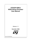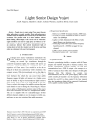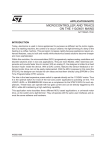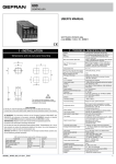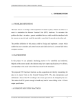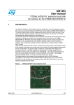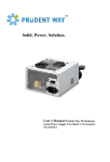
1
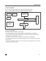
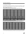
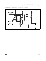
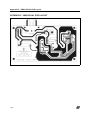
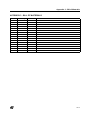
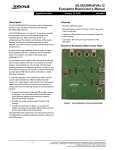
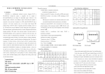
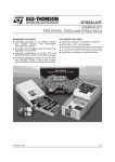
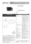
UNIVERSAL MOTOR CONTROL EVALUATION BOARD USER MANUAL 1 INTRODUCTION 1.1 TARGET APPLICATION The UMC01EVAL Evaluation Board is designed for a very low-cost phase control system based on the 8-bit ST62T00C microcontroller. It can be used to control a universal motor powered by a 230 V / 50 Hz mains supply. This type of motor is widely used in home appliances such as: vacuum cleaners, washing machines, power tools and kitchen appliances. In addition to performing a phase angle control algorithm, the board offers many features such as soft start control and 3rd harmonics reduction. Universal motors produce a strong 3rd harmonic current. When the TRIAC conduction is not in full-wave mode, the actual motor current contains high amplitude 3rd harmonics which may not comply with the 3rd harmonics limits of Standard IEC61000-3-2. The UMC01EVAL Evaluation Board introduces an innovative cost-saving solution for reducing 3rd harmonics. WARNING: The MCU is directly linked to the mains voltage supply. No insulation is ensured between the accessible parts and the high voltage. The UMC01EVAL Evaluation Board must be used with care and only by persons qualified for working with electricity at mains voltage levels. Certain precautions have to be taken during emulation to avoid damaging development tools. For more information about safety precautions, please refer to application note AN438 ”TRIAC and Microcontroller Safety Precautions for Development Tools”. This document gives all the information needed to operate the Evaluation Board (how to connect it, how it works). In order to modify specific information and parameters at design level, please refer to the three following Application Notes: ■ AN1448: How to Reduce 3rd Harmonics with ST6200C Motor Control Software ■ AN1449: ST6200 Universal Motor Drive Software ■ AN1476: Low-Cost Power Supply for Home Appliances October 2001 1/14 Table of Contents 1 INTRODUCTION . . . . . . . . . . . . . . . . . . . . . . . . . . . . . . . . . . . . . . . . . . . . . . . . . . . . . . 3 1.1 TARGET APPLICATION . . . . . . . . . . . . . . . . . . . . . . . . . . . . . . . . . . . . . . . . . . . 3 1.2 BLOCK DIAGRAM . . . . . . . . . . . . . . . . . . . . . . . . . . . . . . . . . . . . . . . . . . . . . . . . 5 1.3 LIST OF CONTENTS . . . . . . . . . . . . . . . . . . . . . . . . . . . . . . . . . . . . . . . . . . . . . . 5 1.4 GETTING STARTED . . . . . . . . . . . . . . . . . . . . . . . . . . . . . . . . . . . . . . . . . . . . . . 6 2 FUNCTIONAL DESCRIPTION . . . . . . . . . . . . . . . . . . . . . . . . . . . . . . . . . . . . . . . . . . . 7 2.1 PERFORMANCE . . . . . . . . . . . . . . . . . . . . . . . . . . . . . . . . . . . . . . . . . . . . . . . . . 7 2.2 MAIN FEATURES . . . . . . . . . . . . . . . . . . . . . . . . . . . . . . . . . . . . . . . . . . . . . . . . 7 2.2.1 Phase Angle Control . . . . . . . . . . . . . . . . . . . . . . . . . . . . . . . . . . . . . . . . . . 7 2.2.2 Soft Start . . . . . . . . . . . . . . . . . . . . . . . . . . . . . . . . . . . . . . . . . . . . . . . . . . . 7 2.2.3 3rd Harmonic Limitations . . . . . . . . . . . . . . . . . . . . . . . . . . . . . . . . . . . . . . . 8 2.3 HARDWARE FEATURES . . . . . . . . . . . . . . . . . . . . . . . . . . . . . . . . . . . . . . . . . . 9 2.3.1 ST62T00C Microcontroller . . . . . . . . . . . . . . . . . . . . . . . . . . . . . . . . . . . . . . 9 2.3.2 Capacitive Power Supply . . . . . . . . . . . . . . . . . . . . . . . . . . . . . . . . . . . . . . . 9 2.3.3 TRIAC Drive . . . . . . . . . . . . . . . . . . . . . . . . . . . . . . . . . . . . . . . . . . . . . . . . 10 3 USING THE UMC01EVAL EVALUATION BOARD . . . . . . . . . . . . . . . . . . . . . . . . . . 10 3.1 SYMMETRICAL PHASE ANGLE CONTROL PULSE . . . . . . . . . . . . . . . . . . . . 10 3.2 ASYMMETRICAL GATE PULSE . . . . . . . . . . . . . . . . . . . . . . . . . . . . . . . . . . . . 11 4 CONCLUSION . . . . . . . . . . . . . . . . . . . . . . . . . . . . . . . . . . . . . . . . . . . . . . . . . . . . . . 12 APPENDIX 1 - UMC01EVAL SCHEMATIC DIAGRAM . . . . . . . . . . . . . . . . . . . . . . . . 13 APPENDIX 2 - UMC01EVAL PCB LAYOUT . . . . . . . . . . . . . . . . . . . . . . . . . . . . . . . . . 14 APPENDIX 3 - BILL OF MATERIALS . . . . . . . . . . . . . . . . . . . . . . . . . . . . . . . . . . . . . 14 14 2/14 1 INTRODUCTION 1.2 BLOCK DIAGRAM Figure 1 shows the block diagram of the UMC01EVAL Evaluation Board. Figure 1. Universal Motor Control Evaluation Board Block Diagram Motor Connector Mains Connector TRIAC BTB16 - 600CW Zero Voltage Crossing Capacitive Power Supply ST62T00C MCU Fuse Speed Control Potentiometer 1.3 LIST OF CONTENTS The following items are supplied in the package: – One Universal Motor Control Evaluation Board (ref.: UMC01EVAL ) (including the ST62T00C MCU programmed with the software described in Application Note AN1449) – A small Sintech Universal Motor (100 W) – A CD-ROM, including ST Motor Control product presentation and datasheet – RC Oscillator Phase Angle Control Software programmed in the ST62T00C microcontroller (umcv1r7.st6) – 3rd Harmonics Reduction Software for 1.5 kW vacuum cleaner application (vacuum.st6 file) – A User Manual (this document) 3/14 INTRODUCTION 1.4 GETTING STARTED By following this step-by-step procedure, you can use the UMC01EVAL Evaluation Board to first run the provided Sintech universal motor. Later, you can use the board to run your own AC universal motor. To operate the board correctly, use the following procedure: WARNING: All the following steps must be done by an electrically-skilled technician, because the board has to be plugged to the MAINS voltage, and because NO INSULATION is implemented between the MAINS voltage and the accessible conductive parts. 1. Connect the mains power supply to the MAINS connector on the Evaluation Board. The "SPEED SETTING" potentiometer is used to control the speed of the universal motor. Note that the soft start is implemented during speed adjustments. The potentiometer should not be turned too quickly in order to let the microprocessor take the new order into account. 2. Check that the motor is being controlled properly. Use an oscilloscope to observe the motor winding currents. If there are problems: – Check if the TRIAC gate triggering pulse is correct. – Check that the board is correctly powered on by measuring 5V power supply for the microprocessor. – Check if the FUSE is blown (disconnect the mains voltage before unplugging the fuse). – Reset the MCU by unplugging the mains voltage and waiting for VDD to drop below 0.7V. Then apply the mains voltage and try again to see if the board works. 3. Running with the provided SINTECH Universal Motor in Open Loop Mode When using the provided SINTECH universal motor in open loop mode, the motor speed is changed by using the phase angle control through a TRIAC. Check that the programmed triggering pulse of the TRIAC gates is compatible with the motor to be controlled (see Section 3.2). When your motor is runing in open loop mode, the shunt resistor R1 is not necessary and must be replaced by a jumper. In low cost sensorless speed regulation mode, resistor R1 is used to measure the peak motor current. To run the motor in close loop mode, please refer to the following application note: – AN416: Sensorless Motor Drive with the ST62 MCU + TRIAC The ST6200C MCU can detect the voltage zero crossing, after which it can calculate the phase angle, make the triggering pulse delay and trigger the TRIAC. Before changing the motor control parameters, please refer to Application Note AN1449. 4. Running with your own Standard Universal Motor in Open Loop Mode When using your own universal motor in open loop mode, your motor parameters should be checked, i.e. the phase lag between motor current and input voltage. The triggering 4/14 FUNCTIONAL DESCRIPTION pulse width should be checked as well. 5. 3rd Harmonics Reduction Software When using 3rd harmonics reduction software with a 1500 W vacuum cleaner, replace shunt resistor R1 with a jumper before starting the motor. 6. If you changed the software in the above steps, don't forget to program the Option Byte setting as follows in you MCU: D1 = 1 (Hardware Watchdog Activation) D6 = 1 (RC network oscillator selection) D8 = 1 (LVD reset activation) 2 FUNCTIONAL DESCRIPTION 2.1 PERFORMANCE The UMC01EVAL board is designed to meet the following requirements: ■ Low cost: Capacitive or resistive power supply is used to reduce the system cost as well as the size. Simple voltage zero crossing detection circuit is provided via a current limiting resistor. A crystal oscillator or external resonator are not used. External RESET circuitry is NOT required. ■ IEC61000-3-2 Standards: Using the dedicated software (vacuum.st6 file), the board complies with the 3rd harmonics limits specified in standard IEC61000-3-2. ■ Generic: This board may also used in a wide variety of applications: i.e. light dimmer, power control, universal motor control and thermostat control. 2.2 MAIN FEATURES 2.2.1 Phase Angle Control The speed can be set using the potentiometer mounted on the board. To generate the correct phase angle, the voltage zero crossing signal must be detected. On this board, we use two current limiting resistors to perform voltage zero crossing. The voltage at this port is clamped to 0V and +5V by internal clamping diodes. The microprocessor is able to calculate the phase angle and trigger the TRIAC. It will adjust the voltage applied to the motor. 2.2.2 Soft Start When you start the motor, the motor speed and the Back-EMF are initially set to zero. The mains voltage is applied directly to the motor winding. Since the resistance of the motor winding is very small, it will generate very high inrush current which is 10 to 15 times the nominal current. Using soft start software, the voltage applied to the motor winding ramps up step by step. Therefore, the inrush current at start up will be reduced accordingly. You can modify the ramping up steps and slope by using the software. 5/14 FUNCTIONAL DESCRIPTION 2.2.3 3rd Harmonic Limitations At reduced speeds, universal motors produce very high levels of 3rd harmonics in phase angle mode. The strongest 3rd harmonics are produced when the conduction angle is approximately 90 degrees (refer to Table 1). Table 1. 1500W Vacuum Cleaner Harmonic Currents (measured at a fixed load using the symmetrical phase angle control method) Power Delay Time P (W) t (ms) 250 6.9 320 6.5 535 5.75 590 5.55 780 5.0 900 4.5 1000 4.2 1050 4.0 1090 3.75 1130 3.6 1200 3.5 1300 3.0 1400 2.25 1450 1.6 1480 0.3 Harmonic Current Limit (A) 3 1.918 2.122 2.474 2.513 2.601 2.576 2.515 2.448 2.406 2.331 2.193 1.892 1.386 1.11 0.77 2.30 Harmonic Order & Harmonic Currents (A) 5 7 9 0.92 0.275 0.2 0.931 0.322 0.213 0.92 0.453 0.175 0.923 0.478 0.156 0.883 0.502 0.127 0.859 0.44 0.162 0.834 0.357 0.196 0.82 0.306 0.194 0.806 0.27 0.188 0.793 0.232 0.182 0.743 0.188 0.142 0.612 0.196 0.06 0.33 0.2 0.116 0.138 0.13 0.111 0.107 0.022 0.01 1.14 0.77 0.4 Table 2. 1500W Vacuum Cleaner Harmonic Currents (measured at a fixed load using the asymmetrical phase angle control method) Power Delay Time P (Watt) t1 (ms) t2 (ms) 535W 6.90 5.48 580W 6.90 5.13 700W 6.85 4.74 780W 6.85 4.36 940W 6.13 3.75 1000W 6.04 3.37 1050W 6.08 2.91 1100W 5.19 2.90 1150W 5.20 2.47 Harmonic Current Limit (A) Harmonic Order & Harmonic Currents (A) 3 5 7 9 2.22 0.634 0.281 0.041 2.170 0.532 0.280 0.072 2.115 0.451 0.251 0.157 1.974 0.437 0.241 0.185 1.799 0.371 0.182 0.174 1.595 0.364 0.219 0.105 1.362 0.389 0.234 0.049 1.658 0.204 0.245 0.084 1.349 0.121 0.293 0.052 2.30 1.14 0.77 0.4 In order to suppress 3rd harmonic current in the power line, an innovative, cost-saving solution is used. This control method is based on the modulation of the phase angle delay times and is 6/14 FUNCTIONAL DESCRIPTION easily implemented using the ST62T00C microcontroller software. The test results shown in Table 2 prove the efficiency of this solution. In Table 1, the figures in bold exceed harmonic current limit specifications. 2.3 HARDWARE FEATURES 2.3.1 ST62T00C Microcontroller The MCU used in the UMC01EVAL board is the ST62T00C. This is a basic ST6 microcontroller that embeds a large number of features at minimum cost. The peripheral hardware requirements have been reduced to the minimum: ■ A crystal oscillator or external resonator is not used. Indeed, the internal resonator of the ST62T00C is used to generate the clock. ■ External RESET circuitry is not required due to the internal circuit of the ST62T00C. When programming the MCU EPROM, you have to set the following three options: ■ D1: Hardware Watchdog Activation (as it is not software enabled) ■ D6: RC network oscillator selection ■ D8: Low Voltage Detection option (in order to reset the MCU when the board is plugged to the mains supply). The ST62T00C memory program space is 1024 bytes. The size of the implemented software is 618 bytes. In order to test longer programs, ST62X01C (with 2K bytes of program memory) can also be installed instead of the ST62X00C in the DIL16 socket. 2.3.2 Capacitive Power Supply In order to reduce the board price as much as possible, a capacitive power supply is used instead of a transformer-based supply. This supply can only source an average current lower than 10 mA. For higher currents, capacitor C1 (cf. Annex 1) can be replaced with one having a higher value. A special characteristic of this power supply is that it is a "negative" supply where the Vdd terminal is linked to Neutral. That means that the Vss voltage is 5V below the Neutral value. The TRIAC can be triggered by a negative current (i.e. sourced from the gate). For more information, please refer to the following application note: ■ AN1476: Low Cost Power Supply for Home Appliances 2.3.3 TRIAC Drive A BTB16-600CW device is used on the UMC01EVAL Evaluation Board. It is the most economical AC power switch for operating directly on the 110V/230V mains. It is directly driven by the MCU. The triggering pulse is short in order to minimize the power supply size. The Snub- 7/14 Using the UMC01EVAL Evaluation Board berless TRIAC is driven in quadrants QII and QIII using 60 mA gate current provided by three parallel I/O ports of the ST6200C. This pulse is long enough to ensure that the TRIAC is latched at the end of the pulse. Pulse length can be modified by software if another TRIAC or motor is used. The BTB16-600CW is a Snubberless TRIAC. It is used to turn off inductive loads without requiring a snubber circuit, therefore saving the cost and space of extra components. It is able to drive a 1600 W vacuum cleaner connected to a 230V mains supply. Table 3 sums up the characteristics of TRIAC and MCU performances with various sensitivities. It also gives the gate current we suggest to control correctly the TRIAC for a minimum ambient temperature of 0°C, with the power supply implemented on our board. Table 3. TRIAC and MCU Sensitivity Characteristics MCU Output Capability ST622X ST621X ST620X IOL = 20 mA TRIAC Type Sensitivity (Igt) Suggested Gate Current Connection T & TW Series IGT = 5 mA IG = 10 mA 1 I/O Port S & SW Series IGT = 10 mA IG = 20 mA 1 I/O Port C Series IGT = 25 mA IG = 40 mA 2 I/O Ports in Parallel CW Series IGT = 35 mA IG = 60 mA 3 I/O Ports in Parallel B & BW Series IGT = 50 mA IG = 80 mA 4 I/O Ports in Parallel 3 USING THE UMC01EVAL EVALUATION BOARD 3.1 SYMMETRICAL PHASE ANGLE CONTROL PULSE Figure 2 shows how the gate current pulses are defined for a universal motor. The calculation of phase angle time is explained in Application Note AN1449. Since the universal motor is an induction motor running on an inductive load, there is the risk of misfiring the TRIAC for one or several half cycles if a different power factor is applied. So you should check that the programmed angle is compatible with your own motor. If not, please refer to AN1449 for instruction on how to change these values. 8/14 Using the UMC01EVAL Evaluation Board Figure 2. Gate Current Pulse 3.2 ASYMMETRICAL GATE PULSE Figure 3 shows how the gate pulses are generated in asymmetrical control mode. In this mode, the phase angle is specifically modulated in order to suppress 3rd harmonic current in the power line. 9/14 CONCLUSION Figure 3. Asymmetrical Gate Pulse 4 CONCLUSION The guidelines provided in this document have been given to help you use the UMC01EVAl Evaluation Board properly. This Evaluation Board is designed for controlling universal motors, but it can also be used for a wide variety of applications such as light dimmers, thermostats and heating systems. The main thing to check is that your loads, especially the inductive load, correspond to the programmed data (maximum speed, triggering pulse width, etc.). Then, after certain adjustments to your software (and using the EPROM version of ST6200 MCU), you are able to perform tests using your own universal motor. With this evaluation board, you can take your own measurements and see how much the 3rd harmonic current is reduced by using this method. Fully detailed information about programming is given in Application Notes AN1448 and AN1449. 10/14 Appendix 1 - UMC01EVAL Schematic Diagram APPENDIX 1 - UMC01EVAL SCHEMATIC DIAGRAM VCC J1 NEUTRAL D1 C2 220uF/16V C1 BZX85C5.6 R1 1R/2W 100nF D2 1N4148 R2 3K U1 R4 47K 1 2 3 4 5 6 C4 100nF R6 7 8 VDD VSS OSCIN PA1 OSCOUT PA2 NMI PA3 VPP/TEST PB0 RST PB1 PB7/AIN4 PB3/AIN1 PB6/AIN3 PB5/AIN2 16 R3 150R 15 Q1 14 BTB16-600CW 13 12 11 10 9 220K C3 470nF/400V ST62T00 VCC 16Pin Socket J3 R5 470R/1W R7 MOTOR SPEED J4 220K 10K F1 J2 LINE FUSE 10A 11/14 Appendix 2 - UMC01EVAL PCB Layout APPENDIX 2 - UMC01EVAL PCB LAYOUT 12/14 Appendix 3 - Bill of Materials APPENDIX 3 - BILL OF MATERIALS Item 1 2 3 4 5 6 7 8 9 10 11 12 13 Quantity 1 1 1 1 1 1 1 1 1 1 1 1 2 14 15 1 1 Reference C1 C2 C4 D1 D2 F1 Q1 R1 R2 R3 R4 R5 R6 R7 SPEED U1 Reference 100nF 220uF/16V 100nF BZX85C5.6 1N4148 FUSE 10A BTB16-600CW 1R/2W 3K 150R 47K 470R/1W 220K 220K 10K ST62T00 13/14 Notes: Information furnished is believed to be accurate and reliable. However, STMicroelectronics assumes no responsibility for the consequences of use of such information nor for any infringement of patents or other rights of third parties which may result from its use. No license is granted by implication or otherwise under any patent or patent rights of STMicroelectronics. Specifications mentioned in this publication are subject to change without notice. This publication supersedes and replaces all information previously supplied. STMicroelectronics products are not authorized for use as critical components in life support devices or systems without the express written approval of STMicroelectronics. The ST logo is a registered trademark of STMicroelectronics 2001 STMicroelectronics - All Rights Reserved. Purchase of I2C Components by STMicroelectronics conveys a license under the Philips I2C Patent. Rights to use these components in an I2C system is granted provided that the system conforms to the I2C Standard Specification as defined by Philips. STMicroelectronics Group of Companies Australia - Brazil - China - Finland - France - Germany - Hong Kong - India - Italy - Japan - Malaysia - Malta - Morocco - Singapore - Spain Sweden - Switzerland - United Kingdom - U.S.A. http://www.st.com 14/14