1
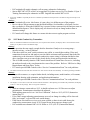
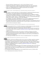
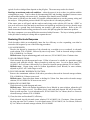
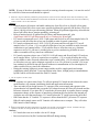
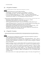
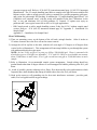
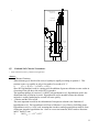
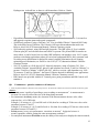
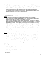
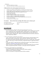
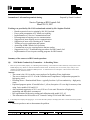
Summation of information promised during: Prepared by Frank Crossland Service Training at HB Controls Ltd. March 26-29, 2007 Training was provided by Mr. Ed Crossland and assisted by Mr. Stephen Werlick. • Hands-on practical service training by Mr. Ed Crossland. • Power point presentation of PC board serviceability. • Implementation of “Service Communication Form”. • Encouragement of ongoing service communication. • Suggestion of more ongoing service communication. • Suggestion of more service training at IC Controls. • Training of service application and options. • Answering all HB Controls Ltd. Questions. • Commitments to review certain practices that are unclear. • Suggestions for Q.C./Troubleshooting procedures for HB Controls Ltd. • Implementation of service parts stocking programs for HB Controls. Summary of the answers to HB Controls questions: Q1: 9110 Model Conductivity Transmitter – in Desalting Water 1. There are 8 pcs 9110 usually display “0” in desalting water measuring. It can't reflect the actual conductivity variety because of the unstable display, why? When we check the transmitter's without sensor, the linearity error can reach 50%, why? All 8 pcs 9110 conductivity transmitters were withdrawn to HB by the user. It resulted in the worst consequence. But IC said its because of the incorrect selection, what's the reason? Answer: • The reason is the 9110 is not the correct analyzer for Desalting Water Application. • The correct Analyzer is 9112 -63 with Calibration and Temperature Compensation program for high purity water. • Desalting Water = Demineralized Water = typically less than 1 µS/cm conductivity = high purity water. • Explained program option -63 needed below 1 µS/cm, but option -63 is too big for memory when using 2-wire models 9110 and 9111. • Also explained superiority of 9111 over 9110 as a 2-wire unit. Discussion of high-purity monitoring and difficulties encountered. • Full explanation of high purity reading and calibration with model 9112 -63. • This information also accessible on IC Controls Catalog CD left with HB Controls. 2. 9110 usually has no display after plugging in. If we touch the PCB by hand, it can display then. How to resolve this kind of problem? Answer: • HB must produce a unit to demonstrate the problem. 1 • • • All units undergo 72 hour burn in and QC at IC Controls before shipment, so this should not happen. Ed Crossland did tests 2007-04-27 with Digital Storage Scope on 9110 at IC Controls and could not duplicate the problem. The current production units should not do this. Possible cause: factory QC reports show units with AD421 “04 series” is a bad batch of 4 – 20mA chips. 04 version AD421 can cause failure after some time in service, if power dips and/or cycles. AD421 does not come back properly and loads the supply so internal voltages are low. Replace AD421 if 04 is on chip. 3. The words on the panel will become blurry after it contacts water. Answer: • HB did not produce a unit to demonstrate the problem. • IC Controls test shows water can leak at top behind panel label if words installed on larger base, because it reduces the glue area. IC Controls will tighten QC and add more glue. Q2: 9111 Model Conductivity Transmitter 1. There was one 9111 had no display after plugging in. We have contacted IC Controls many times, but its still faulted. There is no schematic diagram in the instruction manual. Supply Schematic Answer: • All units undergo 72 hour burn in and QC at IC Controls before shipment, this should not happen. • This is a warranty situation for HB Controls. • IC Controls will supply schematics. • Schematics sent 2007-04-18 to Bai Yun, [email protected]. By: Lisa Stauder 4.11pm. 2 Training Documents plus schematics as PDF. Original also mailed 2007-04-18. • Factory QC reports show units with AD421 “04 series” is a bad batch of 4 – 20mA chips. 04 version AD421 can cause failure after some time in service, if power dips and/or cycles. AD421 does not come back properly and loads the supply so internal voltages are low. Replace AD421 if 04 is on chip. 2. After being checked, tested by our technician and fed back from the user, we make a conclusion that all IC Controls two-wire conductivity analyzers are unqualified. Answer: • IC Controls understands your frustration. • IC Controls explained that this was based on perception due to unsolved service and application issues. HB Controls understands “inefficient service” communication contributed significantly to this perception of the 2-wire conductivity analyzers. • IC Controls provided HB Controls with a “Service Communication Form” to stop this problem. • All units undergo 72 hour burn in and QC at IC Controls before shipment, this should not happen. 3. There are no schematic diagram in two-wire conductivity transmitter instruction manual. its inconvenient to us to service it its out of work.. Answer: 2 • • Ed Crossland will supply schematics; all necessary schematics forthcoming. Sent as PDF 2007-04-18 to Bai Yun, [email protected]. By: Lisa Stauder 4.11pm. 2 Training Documents plus schematics as PDF. Originals also mailed 2007-04-18. 4. If we press “SAMPLE” repeatedly the two-wire Conductivity transmitter will inspect itself. We think its a bug and we hope IC can improve it. Answer: • Ed Crossland will review this feature; it is not a bug, it is deliberate part of the program. • Review shows: When customer wants the Model number, Serial number, or Program Version they can display it. When the SAMPLE key is pressed 4 times consecutively the analyzer starts an identification sequence. This is display only, no reboot involved, no change made to data or customer settings. • IC Controls will change this feature to a menu selection at next regular program revision. Q3: 9112 Model Conductivity Transmitter. 1. When we checked the transmitter with resistance box, if we input the same resistance, the display value is out-of-tolerance and the linearity is very bad even if its in the different range. Answer: • This question does not supply enough detail to determine if analyzer is on wrong range, incorrect wiring, - or has a problem. • If decade resister box used, switch resistance may add in, to cause higher reading. Wires and connections between box and analyzer can also add in resistance and capacitance that looks like conductivity to the electronics. Normal conductivity sensor wiring is isolation-shielded so that drive signal does not get to sense leads, decade boxes do not guard against this interference. • This is an HB warranty situation. HB Controls should stock certain items for service, including the analyzer boards so they can determine the cause of the problem. Refer to: “HB Service Shop Requirements and Spare Parts,” below. • IC Controls provided HB Controls with a “Service Communication Form” for such problems. 2. The distance between the inner and outer electrode is too short to throw off the water absolutely. It results in generating air bubbles. Answer: • To provide an answer, we require further details; including sensor, model number, cell constant, installation drawing with orientation, and application information. • IC Controls provided HB Controls with a “Service Communication Form” for such problems. 3. The display is “0” if we don't connect the resistance with the transmitter. After adjusting zero and full scale potentimeter, the display is still “0”. It has not any change. How can we get the actual zero? Answer: • With no resistance connected to a 9112, it should read near zero. 9112 has no zero adjust potentiometer. Potentiometers should not be adjusted. • With nothing connected it is an “Air Zero Calibration”. Refer to: 9112 (455-212) Instruction manual Page 23. • If 4 to 20mA output adjusting potentiometers are used, no change in reading will be observed. Only “mA output”, zero and full scale would change. • If the Sensor wire and Power wires are in same conduit, a short circuit could destroy the conductivity measurement circuit. If 9112 input blown, then expect no change result. • Ed Crossland sent schematic2007-04-18. Referr to: 9112 (455-212) Instruction Manual, 3 • • Electronic Hardware Alignment page 45; and “Air Zero Calibration” page 23. Schematics sent 2007-04-18 to Bai Yun, [email protected]. By: Lisa Stauder 4.11pm. 2 Training Documents plus schematics as PDF. Original also mailed 2007-04-18. Field Test Verification Model 9112 Conductivity Electronics, refer to attached: d:\PDF\service\9112FieldVerification.pdf 4. The TC response is too slow. About the temperature error, when should we calibrate it with software or hardware? Answer: • TC response is a sensor related issue. To offer an opinion IC Controls needs to know the sensor model number, cell constant, installation details,and application information. • If for Conductivity Standard Calibration, you can speed up the sensor to conductivity standard equilibrium time. Measure the temperature of your standard, enter it using TC “Set” = (measured value) and press “Enter”. Refer to: “Conductivity Menu” 9112 (455-212) instruction manual page 20. Be sure to return TC selection to “Auto” after Calibration. • TC Calibration: Use software calibration Refer to: 9112 (455-212) instruction manual page 45. When calibrating temperature always allow very long thermal equilibrium time. • SS (Stainless Steel) or plastic, if comparing Temperature measured via a SS temperature sensor to Temperature measured inside a large plastic sensor, expect the plastic to transfer heat slowly and the size to also slow temperature response. 5. The acid concentration transmitter is unstable when it tests the standard solution. Why does this display fluctuate? Answer: • This is the model 9112-23 (0 – 15% HCL). It measures very high conductivity (1000 to 800,000 µS/cm) and may be being calibrated with too low conductivity standard. • Is a A1400053 High Conductivity Calibration Kit being used? The kit includes instruction sheet. Service Requirements. Refer to attached d:\pdf\forms\v9603470 High Conductivity Calibration A1400053 Kit.pdf • Without a more detailed description of the problem it is difficult to diagnose the problem. IC Controls needs to know the sensor, model number, cell constant, installation drawing with orientation, application information, plus the Conductivity value of the (2) two Standards used and how they were introduced. • IC Controls provided HB Controls with a “Service Communication Form” for such problems. 6. After we calibrate 0 and 10uS/cm, when we check the 5uS/cm, the error is 0.07, why? Answer: • Readings below 10 µS/cm are difficult to achieve due to carryover of higher conductivity standard on the sensor surfaces. Carryover actually raises the conductivity of the lower standard, so the sensor/analyzer is actually reading correct. Overcome carryover by a three rinse procedure with low standard before taking reading. Refer to: A1400051 Instruction Sheet, “Instructions for Low-Range Conductivity Calibration Kit. Refer to attached d:\pdf\forms\v9603460 Low Conductivity Calibration A1400051 Kit.pdf • The 9112 can be linearity tested with resisters. If 1% resistor is used, resister can be 4.95 to 5.05 and be good. Plus 9112 can vary 0.2% so reading of 4.93 to 5.07 is good. If decade resister box used, switch resistance may add to cause higher reading, and wires and connections between box and analyzer can also add to error. • Ed Crossland recommends HB should buy (1) one A1400051 kit for service, QC. Refer to HB Service Shop Requirements and Spare Parts below. 4 7. After we receive the goods from IC Controls, how can we check the transmitters without sensors? The users and we also want to know it, because there is no any details about it in the instruction manual. Answer: • IC Controls does not recommend calibration with resistors, that is why there are no details about it. Resistors do not include the wires and connections to and from the field senor, the sensor constant, and the sensor electrode condition which also add/subtract to the reading. IC Controls recommends calibration with the sensor wired up using Conductivity Standards for best results. • Analyzer electronics “only” can be checked with resistors. Refer to: “resistance Values for Simulation” Table 9, 9112 (455-212) Instruction Manual Page 44. • Ed Crossland sent printouts of charts that explain this to HB Controls. Sent as PDF 2007-04-18 to Bai Yun, [email protected]. By: Lisa Stauder 4.11pm. 2 Training Documents plus schematics as PDF. Originals also mailed 2007-04-18. 8. There us one 9112 has no any display after plugging in. IC Controls has sent many components to replace, but its still not been resolved. Answer: • Withouta more detailed description of the problem it is difficult to diagnose the problem. • IC Controls runs electronics QC then 72 hour burn-in test on 100% of all electronics, prior to final QC inspection procedure that is documented and stored by serial number. • This is an HB Controls warranty situation. • Most often if a display is blank there is a connector problem that can be eliminated by removing and re-inserting all connections to the board or display itself. Also try replacing the betweenboard connector cable. • IC Controls needs to know the model number, serial number, and history information. Plus the applicable test readings (+/- DC volts at power board and at display board etc) and how they were obtained. • IC Controls provided HB Controls with a “Service Communication Form” for such problems. Q4: 9123 Model pH Transmitter . 1. There were two pcs 9123 has no changes when tested any solutions from starting. Were these two pcs 9123 not inspected before leaving factory? Answer: • IC Controls runs electronics QC then 72 hour burn-in test on 100% of all electronics, prior to final QC inspection procedure that is documented and stored by serial number. This was explained by Ed Crossland. For field test, refer to attached: d:\PDF\service\pH Troubleshooting Made Easy.pdf • It is more likely that the pH sensor suffered an impact in transit or handling and was broken. A full discussion of pH sensor “Broken Glass” symptoms were discussed. • Refer to attached: pH Sensor Analysis form V9600430 for tests to establish status of a pH electrode. d:\pdf\forms\v9600430-ph_electrode_analysis.pdf • Sensor troubleshooting information will be sent to HB Controls: The following pH Sensor Troubleshooting information was taken from page 30 and 31 of the pH Sensor User Manual available on IC Controls website. The entire manual complete with application tips, installation instructions, calibration instructions, cleaning procedures, is available at at www.iccontrols.com The pH Sensor Troubleshooting appears on the next page. 5 pH SENSOR TROUBLESHOOTING In order to troubleshoot a pH sensor, it is very important to be certain that the analyzer used for troubleshooting is functioning correctly. Before testing the pH sensor, be sure the test analyzer is known to be good. FIRST: Inspect electrodes and if dirty or scaled: ➢ Clean with a soft cloth. ➢ Acid clean to remove scale as per Chemical Clean procedure. SECOND: Run buffer tests in (but do not adjust analyzer): ➢ pH 7 buffer; write down reading and response time ➢ pH 4 buffer; write down reading and response time Slow response? Clean again or acid clean overnight in electrode wash solution, A1100091. Make sure that after cleaning response is not longer than 3 minutes. REFERENCE: If pH 7 reads between 6 pH and 8 pH then reference is good. If pH reading outside pH 6 or pH 8, then reference is poor or has failed. pH GLASS: Subtract pH 4 reading from pH 7 reading. ➢ if result is 2.5 to 3, the glass is good. ➢ if result is less than 2.5, then pH electrode is failing and should be replaced. Less responsive pH electrodes can sometimes be regenerated with A1100092 electrode renew solution. Refer to Restoring Electrode Response. THIRD: If pH sensor passes tests, then it is good. Place electrode back in the loop and then run a 2 buffer calibration following the instructions in this manual. FOURTH: If the sensor fails tests: ➢ Replace the pH sensor. ➢ Consider returning sensor to IC Controls for failure analysis if electrode life seems short. IC Controls offers a free electrode and application analysis that may help increase electrode life in your application. Example of analysis: Slow Response – typically due to excessive sample line length and low flow, thus producing long sample transport time to the pH sensor from the sample point. Resolve by adding a fast-flow loop with the sensor in a short side stream, or by shortening the line. Slow response can also be caused by a buildup of dirt in the sample line. In this case the problem could be alleviated by changing the sample point or by installing a dirt settling pot. Troubleshooting Tips for pH Reading spike – characteristic of bubbles in the sample line passing through the sensor or sticking to the pH sensor. Also characteristic of pickup from interference pulses generated from AC lines, when AC loads go off-line. Readings gradually drifting away – the pH sensor can no longer be calibrated. This problem is 6 typical of scale or sludge/slime deposits on the pH glass. The sensor may need to be cleaned. Readings at maximum; under all conditions − either the sensor is in air or there is a problem with the wiring/analyzer setup. Test for shorts by disconnecting BNC and checking impedance between center pin and outside housing with sensor in air. Insulation value should exceed 100 MΩ. If the sensor is OK then use the model 659 portable calibrator/analyzer to test the preamp, wiring and the analyzer. If the problem persists with the 659 in place then it is an analyzer problem. If the sensor tests as still good, and the analyzer and wiring works with the 659, but the “+ERR” or over-scale still occur when the analyzer and sensor are hooked up and placed in service, then the most likely cause is a ground loop short forming, not actually a pH sensor problem. Refer to the 659 instruction manual trouble testing procedures to resolve this pH loop plant site interaction problem. The above symptoms cover most difficulties associated with pH sensors. The key to isolating problems in the pH sensor or analyzer is being able to separate the two. Restoring Electrode Response Used electrodes which are mechanically intact but low efficiency or slow responding, can often be restored to full response by one of the following procedures: 1) SCALE DEPOSITS: Dissolve the deposit by immersion of the electrode tip, overnight (or over weekend), in electrode wash solution, P/N A1100091, followed by rinse in tap water. Soak in electrode storage solution, P/N A1100090 for 1 to 2 hours. Difficult cases: Repeat substituting gentle scale remover, P/N A1100093, then 15 minute rinse. 2) OIL OR GREASE FILMS: Wash electrode tip with detergent and water. If film is known to be soluble in a particular organic solvent, wash with this solvent. Rinse electrode tip with tap water. Let sit in demin water, P/N A1100015, for 2 to 4 hours, followed by 2 to 4 hours in electrode storage solution, P/N A1100090. Difficult cases: Repeat using wash in Sodium hypochlorite (Javex Bleach) in water solution, adjusted to pH 6.5 ± 0.5 with vinegar or acid. 3) PLUGGED OR DRY REFERENCE JUNCTION: Remove the contaminant with one of the above procedures, then soak in electrode storage solution, P/N A1100090 for 24 hours to one week. Difficult cases: Repeat but heat almost to boiling for ½ hour first, then soak in electrode storage solution, P/N A1100090 for 24 hours to one week. 4) BIOLOGICAL GROWTHS: Wash electrode tip with detergent and water. Difficult cases: Wash with Sodium hypochlorite (Javex Bleach) in water solution, adjusted to pH 6.5 ± 0.5 with vinegar or acid. Use rubber gloves, and wash until deposits fall off or turn white. Rinse tip with tap water. Let sit in demin water, P/N A1100015 for 2 to 4 hours, then 2 to 4 hours in electrode storage solution, P/N A1100090. 5) Clean, but slow and less than 85% efficiency: Wash electrode tip with electrode renew solution, P/N A1100092, for 15 minutes. Rinse electrode tip using tap water for 15 minutes. Let sit in demin water, P/N A1100015, for 2 to 4 hours, followed by 2 to 4 hours in electrode storage solution, P/N A1100090. 7 NOTE: If none of the above procedures succeed in restoring electrode response, it is near the end of the useful life of that sensor and should be replaced. 2. What's the range of conductivity suitable for general pH sensor? Need we not select 9025 pH sensor when the conductivity of the water is above 15uS/cm? What's the difference between 9025-25 and 9025-26? Must we use 9025-26 sensor when the conductivity is below 1uS/cm? Can we select 9025-25? Answer: • General purpose pH sensors can handle conductivity from 200 µS/cm to 100,000 µS/cm quite well. Lower than 200 µS/cm expect more possible problems but generally OK down to 50 µS/cm. Above 100,000 µS/cm expect increasing problems. When pH problems appear they often take the form of pH offsets due to junction potentials, poisoning etc. • Refer to attached article: d:\pdf\articles\pH Theory and Measurement.pdf , plus d:\pdf\forms\v9603421 pH Measurement in Low Conductivity Waters.pdf • IC Controls recommends use of 9025-21 pH sensor and flowcell on all clean samples below 50 µS/cm to avoid pH offset due to low ions available to make electrode connections. • IC Controls recommends use of 9025-21-24-25 pH sensor and flowcell (plus 9123) on all samples below 15 µS/cm. (-21) to avoid pH offset due to low ions available to make electrode connections to get constant offset. (-25) to stabilize flow so offset does not vary, eliminate exposure to air so CO2 pH error is avoided, plus to get low conductivity pH buffer in use to achieve reasonable recovery time from calibrations. • IC Controls experience shows use of 9025-21-24-26 pH sensor and flowcell and 9123 analyzer on all samples below 1 µS/cm is required (no exceptions). (-21) to avoid pH offset due to low ions available to make electrode connections to get constant offset. (-26) to critically control flow so offset does not vary, and to eliminate exposure to air so CO2 pH error is avoided. (-26) to get low conductivity pH buffer into pH flowcell without air contamination or flow interruption, to achieve usable recovery time from calibrations. • During the training, high purity sensor ranges and the need for sample panels and sample conditioning where discussed. It was agreed that in the future, all high purity recommendations by HB Controls will be discussed first with IC Controls. 3. The TC response is too slow, why? Answer: • TC response is a sensor related issue. To offer an opinion IC Controls needs to know the sensor model number, cell constant, installation details and application information. • There are trade-offs in design between TC exposure to the water sample and exposure to the electrochemical cell internals that govern the mV balance between the Glass pH electrode and the Reference electrode. If you place the TC outside the pH sensor body it response faster to sample temperature change, at the expense of introducing a transient pH error because the internal mV electrodes are not at that temperature. IC Controls places the TC inside between the pH & Ref. • HB Claims that the IC Controls TC response is slower than the SICC pH sensor TC response. HB will send a sample sensor and IC Controls will conduct tests to compare. They will advise HB Controls of their findings. 4. Please be advised that the mount of the gasket in one needle valve on 9025 (615) backplate is reversed. It resulted in the pipe explosion if the flow rate was big and the water couldn't flow in if the flow rate was small. Answer: • IC Controls does not use a needle valve in 615 design. • Reviewed and solved by Ed Crossland and HB staff during training 8 • Q5: No action needed. 9132 ppm D.O. Transmitter . 1. Could 9132 model transmitter work under 0? What is the lowest temperature it can work at? Answer: • 9132 Specifications were reviewed during the training. • Display Range = 0.0 to 20 mg/L; Accuracy ± 2% of reading or ± 0.02 mg/L. • Lowest reading is 0.02 mg/L ± 0.02 mg/L. (What does 0.00 ± 0.02 mg/L mean?) • Lowest 9132 operation temperature is +5 ºC. (Below +5 ºC place in a heated enclosure.) • Lowest D.O. Sensor operation temperature is +0.0 ºC. (Will actually work slowly in ice, until electrolyte freezes at about -3 to -5, but can damage D.O. Sensor if it freezes.) 2. There are 8 pcs 9132 + 9031 used to measure sewage. White thing appears in the electrolyte. What's it? Why does it appear? Could we still use the sensor? How long is the general D.O. Sensor? • White things; KOH Crystallization, an air bubble in the electrolyte, or PbOH. • • • • Q6: The DO Sensor should still work even with a few white things. 9030 Sewage DO Sensor has long life, can be years. When proper rolling action set up on sewage, 9030 known to last 1 to 5 years. 9031 is low cost sensor without self-clean rolling action, smaller internals, and little tip membrane protection, expect shorter life. During training visit HB Controls was advised to rinse, clean and recharge the sensor. A full demonstration of the model 9030 (802) sensor and its advantages was given. 9030 (802) Sewage DO Sensor sales tips, refer to attached: d:\SERVICE\Technical\DO sales tips.pdf, and IcppmDO.pdf, and SwingArmPic.pdf 9134 ppb D.O. Transmitter 1. What's the requirement for ppb D.O. Sensor mounting? What's the reason for high measured D.O. Value? Why does the high measured D.O. Value not count down? Because there are two pcs 9134 that their measured value are high, but the actual value are low. Answer: • IC Controls discussed membrane leaks, air bubbles, along with the importance of panels for sample conditioning and air bubble dissipation. • Air contains 20.9% oxygen or in parts per billion, 209,000,000 ppb (ppb = μg/L). Water is saturated with dissolved oxygen at 8,240 ppb (refer to Appendix B, 25 °C and 101.3 kPa) so air can saturate about 25,000 times as much water, or at 1 ppb can add an extra ppb to 25,000,000 times as much sample. • High D.O. Readings. The most common problem with low level ppb dissolved oxygen is with air leaks into the sample. Fittings, pressure regulator valves, rotameters, valves and plastic tubing are prone to air leaks. Air leaks can be confirmed by increasing the sample flow. If the D.O. reading decreases with increased flow and returns when the flow returns, a leak is strongly suspected since more volume dilutes the oxygen leaking in. Some components may trap air bubbles producing a similar flow change but not quite full return, plus will slowly fall toward the low ppb readings. Alleviate the problem by finding and eliminating the leak (or eliminating bubble retaining housing). • HB Controls needs to sell a sample panel identical to option -25 for these 9134 ppb DO level 9 systems to operate well. Refer to: 9134 (865-25) instruction manual page 14 “865-25 Component Identification”. The -25 sample handling panel delivers sample to the ppb DO sensor without DO hideout cavities, achieves steady pressure, achieves constant flow, provides magnetite grit bypass, and a point for grab-sample DO checking. In addition the -25 sample handling panel allows “Air Calibration over saturated water” with the sensor still installed in the line. Calibration “in the line” is easy and eliminates 99% of field problems. IC Controls -25 option users enjoy no problems and 5 years typical sensor life on 0.01 to 10.0 ppb applications. • HB Controls needs to add a sample handling system if they buy 9134-5 without sample panel version. Refer to: 9134 (865-25) instruction manual page 61 “Appendix F – Installation: No Sample Panel”. Appendix F — Installation: No Sample Panel Flow Cell Mounting 1) There are mounting screws on the bottom of the cell and a triangle bracket. Allow 8 inches to 12 inches clearance above the flow cell nut for sensor removal. 2) Arrange the cell for up-flow to the inlet, with the cell at an angle of 15 degrees to 45 degrees from vertical (refer to illustration 1). This arrangement will encourage bubbles to pass through the system with minimum dissolved oxygen upset. NOTE: Air has 20.9% oxygen or in parts per billion, 209,000,000 ppb. Water is saturated with dissolved oxygen at 8,240 ppb (see Appendix C, 25 °C and 101.3 kPa) so an air bubble can saturate about 25,000 times as much water, or at 1 ppb can add an extra ppb to 25,000,000 times as much sample. 3) Refer to illustration for recommended sample system arrangement. Sample tubing should use gradual bends rather than 90 degree elbows to avoid entrapped air bubbles producing slow D.O. pull down. 4) Avoid, if possible, pressure reducing valves, filters, flow adjust needle valves and rotameters which frequently have dead chambers that entrap air bubbles that cause slow D.O. pull down. 5) Hook up the sensor to cell grounding wire for best static interference resistance - provides good, stable, low level ppb dissolved oxygen readings. A tm o s p h e ric w a s te M o u n tin g s c re w s G r o u n d le a d In le t 5 0 - 2 0 0 m L / m i n Illustration 1: Sensor flow cell set up 10 • G r a b S a m p le ( O p t i o n a l) C o n s ta n t H ead Tank C a lib r a t e Tee Bypass Tee In le t v a lv e C a li b r a t e v a lv e D r a in Q7: 9160 and 9162 Chlorine Transmitter . 1. Please introduce their theory, calibration and application. Answer: • Chlorine Chemistry When chlorine gas is dissolved in water, it hydrolyzes rapidly according to equation 1. This reaction occurs very rapidly, in only a few tenths of a second at 18 °C. Cl 2 g H 2 Oaq —HOCl aqHCl aq 1) Since HCl (hydrochloric acid) is a strong acid, the addition of gaseous chlorine to water results in a lowering of the pH due to the acidic HCl by-product. The important product of reaction (1) is HOCl or hypochlorous acid. Hypochlorous acid is the disinfectant form of chlorine in water. Hypochlorous acid is unstable because the chlorine molecule is weakly bonded and as a result will react quickly. • Chlorine and the effect of pH The most important reaction in the chlorination of an aqueous solution is the formation of hypochlorous acid. The hypochlorous acid form of chlorine is very effective for killing germs. Hypochlorous acid is a ‘weak’ acid, meaning that it tends to undergo partial dissociation to form a hydrogen ion and a hypochlorite ion. Once in a water environment, HOCl tends to dissociate into H+ and OCl- ions. 1 −1 HOCl aq— H OCl 5) 11 Hydrogen ion is the pH ion, so there is a pH dependency. Refer to: Graph. • • • • • Q8: Hypochlorous acid is also referred to as free available chlorine, or free chlorine. It is taste free and aggressive against germs and organic compounds. 9160 directly measures, using a Galvanic Cell, “Free Available Chlorine” chemical HOCl only. This is the killer form of Chlorine. The Galvanic Cell has a thin membrane that needs care. Refer to: also 9160 (875) Instruction Manual Chlorine Chemistry section. 9162 indirectly measures, using ORP and pH electrodes “The ORP effect of Free Available Chlorine plus pH” and calculates how much HOCl is present. The pH and ORP electrodes are more robust, so can be better, however other ORP influences can introduce error. 9162 is quite good on recirculating applications where pH varies but background ORP is fairly constant; such as cooling tower chlorination for biological control, scrubber chlorination for air cleaning, swimming pool chlorination, etc. Refer to: also 9162 (877-25) Instruction Manual Chlorine Chemistry section. 9161-25 is similar to a 9160 plus a 9162. It directly measures, using a Galvanic Cell, “Free Available Chlorine” chemical HOCl, plus pH and calculates how much “Total Free Chlorine” is present. “Total Free Chlorine” is HOCl plus OCl - which co-exist in a pH dependent way. 916125 measures “Total Free Chlorine”, the form of Chlorine desired for drinking water applications. Refer to: also 9161 (876-25) Instruction Manual Chlorine Chemistry section. HB Controls was provided with the IC Controls power point presentation and HB Controls will translate it. Commonness – question common to all analyzers 1. Please explain the difference between accuracy and precision. We need both of them in the instruction manual and selection guide. Answer: • Accurate means “capable of providing a correct reading or measurement.” A measurement is accurate if it correctly reflects the size of the thing being measured. • For instruments Accuracy means, the closeness of the measurement to the true value, often expressed as ± x% of full scale. Example 1: If accuracy is ± 2% and full scale is 100, then for a reading of 25 the true value can be anywhere between 23 and 27. Example 2: If accuracy is ± 0.5% and full scale is 100, then for a reading of 25 the true value can be anywhere between 24.5 and 25.5. • Precise means “exact, as in performance, execution, or amount.” In physical science it means”repeatable, reliable, getting the same measurement each time.” • For analytical instruments Precision means, the ability of the analyzer to display the value measured, 12 • • often expressed as ± 0.01 digits, when delivered an electronic signal from a sensor simulator. Example 1: If precision is ± 0.1 digits, then for a value measured of 25 the display can be between 24.9 and 25.1. Example 2: If precision is ± 0.01 digits, then for a value measured of 25 the display can be between 24.99 and 25.01. For analytical instruments Accuracy involves the ability of the analyzer with its inter-connections and its sensor, together with the technician's technique and skill, plus the quality and condition of calibration standards used, to display the true value measured. Achievable under ideal conditions. For analytical instruments Repeatability involves the ability of the analyzer with its interconnections and its sensor plus the sensor condition, together with the technician's technique, patience and skill, plus the quality and condition of calibration standards used, to display the true value measured repeatedly. Due to the multiple variables involved this term is not recommended. 2. What's the temperature benchmark for standard solution, calibration and TC? Is the measured value at actual temperature or benchmark temperature? Answer: • Benchmark temperature. 25°C. If TC is off; actual temperature is benchmark. • If at calibration the TC is off (selected to “SET”), then user must measure standard temperature and edit SET value to actual temperature measured in standard. Then return the selection to AUTO when finished. • If at calibration the TC is on (selected to “AUTO”), then user must allow time for thermal equilibrium of standard temperature and sensor temperature; however, the analyzer will compensate the actual reading to the benchmark temperature 25°C. • When measuring the measured value from the sensor is always at the actual sensor temperature. If the TC is selected to AUTO the measured value is corrected to benchmark and displayed as the 25°C value. • When measuring the measured value from the sensor is always at the actual sensor temperature. If the TC is selected to SET and the selected value is 25°C the measured value is not corrected to benchmark. The displayed value is the measured value from the sensor at the actual sensor temperature. • When measuring, if the TC is selected to SET and the selected value is not 25°C the measured value is corrected to the difference between the non- 25°C and 25°C. The displayed value then is the measured value from the sensor at the actual sensor temperature with the partial correction: this is not recommended.. 3. All the potentiometers are not encapsulated before the transmitters leave factory, so the resistance of the potentiometers is easy to change. It results in error such as output current and temperature. Answer: • Orders shipped after 2007-05-10 have red varnish on the potentiometers. 4. IC Controls should change the drawings, picture and models into HB. The “IC” words and IC's models can't be used in the instruction manual and on the goods. Answer: • SICC, before forming HB Controls, agreed with IC Controls that SICC will translate all IC Controls literature as needed for the Chinese market. This agreement reflected IC Controls limited size, when compared to SICC, and no knowledge of Chinese. Translation and changes to HB are the responsibility of HB Controls and SICC. • Discussion began concerning HB's instructions manuals. They don't like their own quality and 13 • • have asked IC Controls to do it for them. IC Controls agrees the quality is low and is surprised they are in English. Many problems would disappear if the manuals where in Chinese. Translation and changes to HB are the responsibility of HB Controls and SICC. IC Controls does not have the resources or knowledge of Chinese to do this work. If HB can use Open Office files, IC Controls could supply the original computer files to assist (make easier) this work for HB. 5. How long is the products warranty? When does it start from? Answer: • A one year WARRANTY will be offered on instruments. This starts date of shipment from HB Controls to the customer, and not to exceed 18 months from date of shipment from IC Controls. • A 90 day warranty on Sensors, when new out of the box. This starts date sensor box opened and sensor installed at customer, not to exceed 6 months from shipment date from HB Controls to the customer, and not to exceed 9 months after shipment from IC Controls Note: Sensor warranty reflects the impact of variable process conditions that may coat, poison, abrade, cook, or otherwise affect the sensor life. Sensors are like batteries, when used on easy applications they can last years, on hard applications expect short life. • The WARRANTY shall be SHARED between IC CONTROLS and HB CONTROLS. Shared warranty gives HB Controls in China control, so customer gets best treatment. Refer to attached: d:\pdf\forms\HB_Warranty_Policy.pdf • SHARED WARRANTY works like this; A) HB CONTROLS decides when warranty replacement or repair is needed, replacement is made immediately from HB Controls CHINA NATIONAL STOCK. B) HB Controls does not immediately return defective goods to IC CONTROLS, but instead an RA report showing qualifying “specific” cause of failure is returned immediately. To qualify for Shared Warranty cause of failure must be “specific” (such as +5.00 VDC supply is defective at +3.2 VDC), “generalized” cause (such as “it no work”) do not qualify. The defective goods are tagged with the RA number plus cause of failure, and are retained for 18 months for possible consolidated annual return to IC Controls. C) IC CONTROLS share will replace documented WARRANTY failure item NO CHARGE, F.O.B. Orangeville, Canada; based on the HB Controls RA report showing cause of failure that was sent to IC Controls immediately. D) HB Controls share will be labor of repair and documentation of cause of failure etc. plus cost of import of the free WARRANTY replacement item from IC CONTROLS. • Report Showing Cause of Failure. As warranty replacement will be decided by HB Controls, IC Controls requires a report describing the cause of failure for our records before we provide the NO CHARGE replacement. HB Controls must perform the diagnostics on the equipment to determine warranty. • Inventory for HB Controls. HB Controls shall keep a service/warranty inventory along with sales inventory. This stock should consist of warranty replacement parts such as replacement circuit boards so they can provide quick service support to their customers. • Annual Return of Defective Goods. At the request of either HB Controls or IC Controls items deemed defective by HB Controls and replaced under warranty will be returned to IC Controls for evaluation. Items will consolidated into a single annual shipment, to keep costs down. 6. The quality, grade and credit of IC's water analyzers are also low. What can IC do for improvement? Answer: 14 • • • • • • • This view is not reflected from other areas of the world. The service training was directed at addressing this problem. Language may play a part in this situation in China. From the service training experience IC Controls learned that the instruction manuals are not translated, and may not be in use. Much valuable information is lost to the user or service technician, that is available in the manuals. The answers to many questions submitted are in the manuals. IC Controls thinks HB Controls should translate the manuals and then many problems will go away. From the service training experience IC Controls learned that there is no SERVICE SPARE PARTS STOCK in CHINA. Much time is lost to the user and service technician because they can not substitute a known good item to prove or disprove. IC Controls thinks HB Controls should acquire the Service Shop Requirements and Spare Parts recommended and then many problems will go away. Refer to: HB Service Shop Requirements and Spare Parts under Training Q4 below. IC Controls has instituted changes where specifics were requested by HB Controls to help meet these concerns, Refer to: above details. In the past many service requests have had little to no information for IC Controls experts to determine what is happening in the field in China. More detail is needed than “it no work”. This reduces IC Controls ability to offer HB Controls assistance. It was explained to HB Controls that a good system of service communication will improve the perception of IC Controls analyzers. IC Controls has issued a “SERVICE COMMUNICATION FORM” form to help improve communications. HB Controls should add Chinese translation to the form resulting in a two language form, then both Chinese and Canadian technicians can understand better. The next version of IC Controls analyzers will have more features desired by HB Controls. 7. There is only one fuse in each transmitter. Why doesn't provide 2-3 extra fuses for standby? Because the transmitter can't be used anymore is the fuse is faulted. Answer: • The fuse specification is Littelfuse Micro Fuse type 273.250 refer to www.littelfuse.com for full details. HB Controls may source the fuse locally. 8. The structures of all IC's transmitters are not suit for panel mounting. The quality of the PCB is too bad and the transformer is easy out of work. Answer: • Yes IC Controls analyzer case is for surface mounting. There are optional panel mount kits for that purpose. The new analyzer line will have dual purpose surface/panel mount case. • The transformer mount has been improved to prevent damage in long shipment. 9. What temperature is the TC resistance at? Answer: • All analyzers with TC circuit for Pt 1000 are shipped with a 1070 ±1% resistor across the TC terminals. The 1.07K simulates 18oC. When used the analyzer should select TC, SET, 18. • When the resistor is removed and a sensor PT 1000 TC leads hooked up, the PT 1000 will vary with the actual temperature. When used the analyzer should select TC, AUTO. Q9: Configuration 1. What's the basic configuration of 9132 ppm D.O. Analyzer that can insure normal use? PPM D.O. Analyzer is mainly used for 15 measuring sewage, so it has higher requirement to D.O. Sensor. IC should provide the basic accompanying fill solution. Answer: • Basic configuration is 9132 with 9030 for sewage. This is very popular in America. Works very well and stays quite clean in sewage. Some sewage treatment plants get 3 to 5 years of life from 9030 with 9132 before replacing the 9030. • During the training there was a full discussion of waste water DO and sensor application. • IC Controls does supply the electrolyte with the sensor. The electrolyte and membrane module are factory installed, the 9030 is ready to operate as received. 2. Please provide the packing list of all IC's transmitters and sensors. Because we don't know the details about the accessories, such as calibration kit, fill solution, membrane and so on. 9032 model D.O. Sensor has not accompanying fill solution and membrane, so we must pay for them, but 9134 and 9160 have them, we needn't pay for them again. Answer: • IC Controls will make packing slips for these products and send with the shipments. • 9134 is ppb level DO sensor that rapidly degrades if in air with oxygen at 209,000,000 times normal measuring range. It is shipped dry with a bottle of electrolyte. • 9160 is a Chlorine sensor that is shipped charged and ready to use. This avoids user damage to the internal parts by curious individuals. There is normally no Chlorine in the air so the sensor is not degraded. It is shipped without a bottle of electrolyte since it is in the sensor as received. • 9032 is ppm DO sensor that is less effected by oxygen in the air, so it is shipped charged and ready to use. This avoids inadvertent damage by users to the internal parts. The sensor is shipped without a bottle of electrolyte and membrane module since they are in the sensor as received. It should not be necessary to purchase supplies if the sensor is not disassembled. • HB Controls claims that some 9032 sensors had fill solution, others don't. IC Controls will review its policy. 3. In order to avoid awful affection and consequence, when we inquire the goods, please check the models to insure the analyzer can work normally. Answer: • IC Controls will be pleased to review the applications. • In order to review the applications and the suitability of the instrument selected IC Controls needs the application information with the orders. Please provide filled out application analysis sheet for each loop on the orders. • In order to review the applications and the suitability of the instrument selected IC Controls needs the sensor-analyzer loop match for the orders. Please provide the orders with matched pairs of sensor-analyzer with identification connection to applicable application analysis sheet. Training Q1: Training 1. Please introduce and explain the specialty, theory, calibration , service and troubleshooting for all IC's analyzers. • Explained by Ed Crossland. 2. Please introduce the selection guide, configuration and application for all IC Controls analyzers. • Explained by Stephen Werlick. 3. Please introduce typical applications in some important field, especial for the different selection and configuration of conductivity and pH in different field. 16 • • • • • • • • • • • • • For conductivity refer to attached: d:\pdf\articles\CondMeasurment.pdf For pH refer to attached: d:\pdf\articles\pH Theory and Measurement.pdf For High Temperature pH refer to attached: d:\pdf\articles\pH_hitmp.pdf For Boiler pH refer to attached: d:\pdf\forms\v9603421 pH Measurement in Low Conductivity Waters.pdf For Boiler Applications refer to attached: d:\Technical\CONDUCT\boiler.pdf For Boiler Dissolved Oxygen refer to attached: d:\pdf\articles\Boiler Water D.O. Control.pdf For Chlorine Measurement refer to attached: d:\SALES\Technical_Notes\Chlorine.pdf For pH Application Questionnaire refer to attached: d:\pdf\articles\questionnaire_pH.pdf For Conductivity Application Questionnaire refer to attached: d:\pdf\articles\questionnaire_Conductivity.pdf For ppm Dissolved Oxygen refer to attached: d:\SALES\Technical_Notes\ppmDO.pdf For ppb Dissolved Oxygen refer to attached: d:\SALES\Technical_Notes\ppbDO.pdf For DO Application Questionnaire refer to attached: d:\pdf\articles\questionnaire_DO.pdf For Chlorine Application Questionnaire refer to attached: d:\pdf\articles\questionnaire_Chlorine.pdf 4. What requirements have IC for our after service. • Further training at IC Controls facility • for HB Controls service manager and associate. HB Controls should have the following minimum service stock. ED Crossland developed the following: HB Service Shop Requirements and Spare Parts. SERVICE TOOLS Required Voltage Simulator (Digital): Capable of ±0.0001 mV (100 μV) Max. Zero Error of ±100 μV DATEL Model DVC-350A or equivalent. with shielded output leads. Multi Meter (Digital): Capable of ±0.001 mV Capable of ±0.08 mA FLUKE Model 77 Series III 2nd Multi Meter (Digital): Capable of 2000 MΩ ±5% Wavetek Meterman Model 15XL pH/ORP Simulator Capable of ±414mV through 100MΩ Capable of 0 to 14 pH in 1 pH steps IC Controls Model 659-1-2-4-5-6 Cond. Test Resistor Tree: Electronics Test Only – 1.0 Cell Constant 1% resisters 100Ω, 1000Ω, 10000Ω DO PPM Test Resistor Tree: Electronics Test Only 1% resisters 200kΩ, 402kΩ, 1MΩ, 2MΩ DO PPB Test Resistor Tree: Electronics Test Only 1% resisters 10kΩ, 100kΩ, 1MΩ, 10MΩ, 100MΩ Two Wire Power Supply: IC Controls Model 540 17 Source of Deionized Water Printed Circuit Boards 9123 9112 9132 9161 9134 1) A9051008-H, pH Power Board 1) A9051009-H, Micro/Display Board, with pH A9041011 XB-9123. 1) A9051010-H, Conductivity Power Board 1) A9051009-H, Micro/Display Board, with Cond. A9041011 XB-9112. 1) A9051019-H, PPM DO Power Board 1) A9051009-H, Micro/Display Board, with PPM DO A9041011 XB-9132. 1) A9051063-H, Total free Chlorine Power Board. 1) A9051009-H, Micro/Display Board, with TF Chlorine A9041011 XB-9161. 1) A9051029-H, PPB DO Power Board. 1) A9051030-H, PPB DO Display Board, with PPB DO A9041011 XB-9134. Component Level SERVICE TOOLS Required 1) DESOLDERING TOOL, with digital controlled Temperature and Vacuum similar to HAKKO 474 1) SOLDERING IRON, with digital controlled Temperature similar to HAKKO 936-12 Components 2) A9201014-H , 16 Wire Inter-connector Cable, 2 ends 2) A9081012-H , Transformer HDSC30F 5) A9160024-H , 1/4A Micro fuse 2) A9021002-H, Transistor 2N3904 2) A9032027-H , ICL7642 Two Wire ½ Din Series Boards Board Sets: These boards are matched sets, do not mix with existing sets. ½ Din Conductivity Set: 1) A9051057-H, Conductivity Power Board. 1) A9051058-H, Display Board with Cond. A9041012 XE-9111 ½ Din pH/ORP Set: 1) A9051060-H, pH/ORP Power Board 1) A9051058-H, Display Board with pH/ORP A9041012 XE-9121 ½ Din PPM DO Set: 1) A9051061-H, PPM DO Power Board 1) A9051058-H, Display Board with PPM DO A9041012 XE-9131 Component Level 2) A9201014-H, 16 Wire Inter-connector Cable, 2 ends 2) A9031094-H, ICA, AD421 2) A9021002-H, Transistor 2N3904 2) A9021026-H, Transistor Fet, ND2020L 2) A9031001-H, ICA, ICL8212 2) A9032044-H, ICA, ICM7555 Two Wire Economical Series Boards 2) A9051038-H, Display Board. Board Sets: These boards are matched sets, do not mix with existing sets. Conductivity Set: 1) A9051041-H, Conductivity Power Board. 1) A9051039-H, Micro Board with Cond. A9041012 XE-9110 pH/ORP Set: 1) A9051040-H, pH/ORP Power Board 1) A9051039-H, Micro Board with pH/ORP A9041012 XE-9120 18 1) 1) PPM DO Set: A9051054-H, PPM DO Power Board A9051039-H, Micro Board with PPM DO A9041012 XE-9130 Calibration Kits with needed equipment and instructions. 1) 1) 1) 1) 1) 1) 1) 1) 1) 1) 1) 1) A1400051 Low Conductivity Calibration Kit for cell constants 0.01 µS/cm to 0.2 µS/cm A1400052 Medium Conductivity Calibration Kit for cell constants 0.1 µS/cm to 5.0 µS/cm A1400053 High Conductivity Calibration Kit for cell constants 10.0 µS/cm to 50.0 µS/cm A1400054 Conductivity Sensor Chemical Cleaning Kit for all sensors A1600050 pH Calibration Kit A1600061 ORP Calibration Kit A1100216 4.10 pH Low Conductivity Buffer with instructions A1100217 7.00 pH Low Conductivity Buffer with instructions A1100216 10.0 pH Low Conductivity Buffer with instructions A1100219 Neutral pH Low Conductivity sample Adjusting Solution with instructions A1100193 Zero DO Standard A1100194 DO Sensor Cleaning Solution Test Sensors: Known Good Sensor working with Analyzer, proves analyzer good. For pH analyzer proving: For Conductivity analyzer proving: For PPM DO analyzer proving: 614-34 plus a 600-T(9123) pH Interface 404-1.0 825-21 Q2: Communication 1. How to establish quick effective communication channel and resolvent when the goods are out of work. • Service Communication Form, IC Controls supplied English version at training • course. Also the form is available and can be downloaded from IC Controls website. (www.iccontrols.com) Service Communication Form, HB Controls to translate English version and add Chinese to English to make a 2 language form. Chinese and Canadian technician can then have better and faster communication channel. 2. If the new sensor has failure, IC should replace it for free right now. • Yes IC Controls agrees. Refer to the procedure for • • • Shared Warranty replacement that involves HB Controls decides, documents why, request replacement, Question 8 Answer 5 above. IC Controls needs to know both failure symptoms, time in service, customer name, serial number etc on RA Form, plus IC Controls need to know all application details on Application Analysis Form. If the sensor is pH, IC Controls also needs “pH Electrode Analysis” form V9600430. Refer to attachment: d:\pdf\forms\v9600430-ph_electrode_analysis.pdf When a sensor fails a Warranty/Application review needs to be preformed. The review should address any application problems. Example: Is it the right sensor for the application? 3. How can we test, check and judge IC's new arrival goods' quality? • Ed Crossland to send QC procedure for HB Q C use. Field Test Verification 9112 Conductivity Electronics. Refer to attached: d:\PDF\service\9112FieldVerification.pdf Field Test Verification 9132 ppm DO Electronics.Refer to attached: 19 d:\PDF\service\9132FieldVerification.pdf For pH refer to attached: d:\PDF\service\pH Troubleshooting Made Easy.pdf 4. What new production will IC promote? • IC Controls introduced their new analyzer model under development. Attachments HB_Warranty_Policy.pdf v9600430-ph_electrode_analysis.pdf v9603421 pH Measurement in Low Conductivity Waters.pdf v9603440 Conductivity Calibration A1400052 Kit.pdf v9603460 Low Conductivity Calibration A1400051 Kit.pdf v9603470 High Conductivity Calibration A1400053 Kit.pdf v9603490 Conductivity Chemical Cleaning A1400054 Kit.pdf CondMeasurment.pdf pH Theory and Measurement.pdf pH_hitmp.pdf ppmDO.pdf DO sales tips.pdf ICppmDO.pdf SwingArmPic.pdf boiler.pdf ppbDO.pdf Boiler Water D.O. Control.pdf Chlorine.pdf questionnaire_pH.pdf Questionaire_Conductivity.pdf questionnaire_DO.pdf questionnaire_Chlorine.pdf 9112FieldVerification.pdf 9132FieldVerification.pdf pH Troubleshooting Made Easy.pdf 20