1
2308-900-01.qxp
7/28/08
11:07 AM
Page 1
www.keithley.com
www.keithley.com
Model 2308 Portable Device
Battery/Charger Simulator
Model 2308 Portable Device
Battery/Charger Simulator
User’s Manual
User’s Manual
2308-900-01 Rev. A / July 2008
2308-900-01 Rev. A / July 2008
A
G R E A T E R
M E A S U R E
O F
C O N F I D E N C E
A
G R E A T E R
M E A S U R E
O F
C O N F I D E N C E
.
WARRANTY
Keithley Instruments, Inc. warrants this product to be free from defects in material and workmanship for a period of
one (1) year from date of shipment.
Keithley Instruments, Inc. warrants the following items for 90 days from the date of shipment: probes, cables,
software, rechargeable batteries, diskettes, and documentation.
During the warranty period, Keithley Instruments will, at its option, either repair or replace any product that proves
to be defective.
To exercise this warranty, write or call your local Keithley Instruments representative, or contact
Keithley Instruments headquarters in Cleveland, Ohio. You will be given prompt assistance and return instructions.
Send the product, transportation prepaid, to the indicated service facility. Repairs will be made and the product
returned, transportation prepaid. Repaired or replaced products are warranted for the balance of the original
warranty period, or at least 90 days.
LIMITATION OF WARRANTY
This warranty does not apply to defects resulting from product modification without Keithley Instruments’ express
written consent, or misuse of any product or part. This warranty also does not apply to fuses, software,
non-rechargeable batteries, damage from battery leakage, or problems arising from normal wear or failure to follow
instructions.
THIS WARRANTY IS IN LIEU OF ALL OTHER WARRANTIES, EXPRESSED OR IMPLIED, INCLUDING ANY
IMPLIED WARRANTY OF MERCHANTABILITY OR FITNESS FOR A PARTICULAR USE. THE REMEDIES
PROVIDED HEREIN ARE BUYER’S SOLE AND EXCLUSIVE REMEDIES.
NEITHER KEITHLEY INSTRUMENTS, INC. NOR ANY OF ITS EMPLOYEES SHALL BE LIABLE FOR ANY
DIRECT, INDIRECT, SPECIAL, INCIDENTAL, OR CONSEQUENTIAL DAMAGES ARISING OUT OF THE USE
OF ITS INSTRUMENTS AND SOFTWARE, EVEN IF KEITHLEY INSTRUMENTS, INC. HAS BEEN ADVISED IN
ADVANCE OF THE POSSIBILITY OF SUCH DAMAGES. SUCH EXCLUDED DAMAGES SHALL INCLUDE, BUT
ARE NOT LIMITED TO: COST OF REMOVAL AND INSTALLATION, LOSSES SUSTAINED AS THE RESULT OF
INJURY TO ANY PERSON, OR DAMAGE TO PROPERTY.
A
G R E A T E R
M E A S U R E
O F
C O N F I D E N C E
Keithley Instruments, Inc.
Corporate Headquarters • 28775 Aurora Road • Cleveland, Ohio 44139
440-248-0400 • Fax: 440-248-6168 • 1-888-KEITHLEY (1-888-534-8453) • www.keithley.com
3/07
Model 2308 Portable Device
Battery/Charger Simulator
User’s Manual
©2008, Keithley Instruments, Inc.
All rights reserved.
Any unauthorized reproduction, photocopy, or use the information herein, in whole or in part, without the prior written
approval of Keithley Instruments, Inc. is strictly prohibited.
TSP, TSP-Link, and TSP-Net are trademarks of Keithley Instruments, Inc. All other brand names are trademarks or
registered trademarks of their respective holders.
Cleveland, Ohio, U.S.A.
Document Number: 2308-900-01 Rev. A / July 2008
Safety Precautions
The following safety precautions should be observed before using this product and any associated instrumentation. Although some
instruments and accessories would normally be used with non-hazardous voltages, there are situations where hazardous conditions may
be present.
This product is intended for use by qualified personnel who recognize shock hazards and are familiar with the safety precautions required
to avoid possible injury. Read and follow all installation, operation, and maintenance information carefully before using the product. Refer
to the user documentation for complete product specifications.
If the product is used in a manner not specified, the protection provided by the product warranty may be impaired.
The types of product users are:
Responsible body is the individual or group responsible for the use and maintenance of equipment, for ensuring that the equipment is
operated within its specifications and operating limits, and for ensuring that operators are adequately trained.
Operators use the product for its intended function. They must be trained in electrical safety procedures and proper use of the instrument.
They must be protected from electric shock and contact with hazardous live circuits.
Maintenance personnel perform routine procedures on the product to keep it operating properly, for example, setting the line voltage or
replacing consumable materials. Maintenance procedures are described in the user documentation. The procedures explicitly state if the
operator may perform them. Otherwise, they should be performed only by service personnel.
Service personnel are trained to work on live circuits, perform safe installations, and repair products. Only properly trained service
personnel may perform installation and service procedures.
Keithley Instruments products are designed for use with electrical signals that are rated Measurement Category I and Measurement
Category II, as described in the International Electrotechnical Commission (IEC) Standard IEC 60664. Most measurement, control, and
data I/O signals are Measurement Category I and must not be directly connected to mains voltage or to voltage sources with high transient
over-voltages. Measurement Category II connections require protection for high transient over-voltages often associated with local AC
mains connections. Assume all measurement, control, and data I/O connections are for connection to Category I sources unless otherwise
marked or described in the user documentation.
Exercise extreme caution when a shock hazard is present. Lethal voltage may be present on cable connector jacks or test fixtures. The
American National Standards Institute (ANSI) states that a shock hazard exists when voltage levels greater than 30V RMS, 42.4V peak,
or 60VDC are present. A good safety practice is to expect that hazardous voltage is present in any unknown circuit before measuring.
Operators of this product must be protected from electric shock at all times. The responsible body must ensure that operators are
prevented access and/or insulated from every connection point. In some cases, connections must be exposed to potential human contact.
Product operators in these circumstances must be trained to protect themselves from the risk of electric shock. If the circuit is capable of
operating at or above 1000V, no conductive part of the circuit may be exposed.
Do not connect switching cards directly to unlimited power circuits. They are intended to be used with impedance-limited sources. NEVER
connect switching cards directly to AC mains. When connecting sources to switching cards, install protective devices to limit fault current
and voltage to the card.
Before operating an instrument, ensure that the line cord is connected to a properly-grounded power receptacle. Inspect the connecting
cables, test leads, and jumpers for possible wear, cracks, or breaks before each use.
11/07
When installing equipment where access to the main power cord is restricted, such as rack mounting, a separate main input power
disconnect device must be provided in close proximity to the equipment and within easy reach of the operator.
For maximum safety, do not touch the product, test cables, or any other instruments while power is applied to the circuit under test.
ALWAYS remove power from the entire test system and discharge any capacitors before: connecting or disconnecting cables or jumpers,
installing or removing switching cards, or making internal changes, such as installing or removing jumpers.
Do not touch any object that could provide a current path to the common side of the circuit under test or power line (earth) ground. Always
make measurements with dry hands while standing on a dry, insulated surface capable of withstanding the voltage being measured.
The instrument and accessories must be used in accordance with its specifications and operating instructions, or the safety of the
equipment may be impaired.
Do not exceed the maximum signal levels of the instruments and accessories, as defined in the specifications and operating information,
and as shown on the instrument or test fixture panels, or switching card.
When fuses are used in a product, replace with the same type and rating for continued protection against fire hazard.
Chassis connections must only be used as shield connections for measuring circuits, NOT as safety earth ground connections.
If you are using a test fixture, keep the lid closed while power is applied to the device under test. Safe operation requires the use of a lid
interlock.
If a
The
screw is present, connect it to safety earth ground using the wire recommended in the user documentation.
!
symbol on an instrument indicates that the user should refer to the operating instructions located in the user documentation.
The
symbol on an instrument shows that it can source or measure 1000V or more, including the combined effect of normal and
common mode voltages. Use standard safety precautions to avoid personal contact with these voltages.
The
The
symbol on an instrument shows that the surface may be hot. Avoid personal contact to prevent burns.
symbol indicates a connection terminal to the equipment frame.
If this
symbol is on a product, it indicates that mercury is present in the display lamp. Please note that the lamp must be properly
disposed of according to federal, state, and local laws.
The WARNING heading in the user documentation explains dangers that might result in personal injury or death. Always read the
associated information very carefully before performing the indicated procedure.
The CAUTION heading in the user documentation explains hazards that could damage the instrument. Such damage may invalidate the
warranty.
Instrumentation and accessories shall not be connected to humans.
Before performing any maintenance, disconnect the line cord and all test cables.
To maintain protection from electric shock and fire, replacement components in mains circuits - including the power transformer, test leads,
and input jacks - must be purchased from Keithley Instruments. Standard fuses with applicable national safety approvals may be used if
the rating and type are the same. Other components that are not safety-related may be purchased from other suppliers as long as they
are equivalent to the original component (note that selected parts should be purchased only through Keithley Instruments to maintain
accuracy and functionality of the product). If you are unsure about the applicability of a replacement component, call a Keithley Instruments
office for information.
To clean an instrument, use a damp cloth or mild, water-based cleaner. Clean the exterior of the instrument only. Do not apply cleaner
directly to the instrument or allow liquids to enter or spill on the instrument. Products that consist of a circuit board with no case or chassis
(e.g., a data acquisition board for installation into a computer) should never require cleaning if handled according to instructions. If the
board becomes contaminated and operation is affected, the board should be returned to the factory for proper cleaning/servicing.
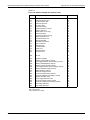
Table of Contents
Section
1
Topic
Page
Getting Started ....................................................................................... 1-1
Overview..................................................................................................... 1-2
Applications ................................................................................................ 1-2
Performance features ................................................................................. 1-2
Warranty information .................................................................................. 1-2
Contact information..................................................................................... 1-2
Specifications.............................................................................................. 1-3
Inspection ................................................................................................... 1-3
Options and accessories ............................................................................ 1-3
Power supply overview ............................................................................... 1-3
Remote display option ................................................................................ 1-5
Power-up .................................................................................................... 1-7
Line power connection ......................................................................... 1-7
Power-up sequence ............................................................................. 1-7
Fuse replacement ................................................................................ 1-8
Display modes ............................................................................................ 1-8
Default settings ......................................................................................... 1-11
Setups - Save, Power-on, and Recall ................................................ 1-12
Menu......................................................................................................... 1-12
Getting around the MENU ........................................................................ 1-14
SCPI programming ................................................................................... 1-15
2
Basic Power Supply Operation .......................................................... 2-1
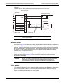
Test connections ........................................................................................ 2-2
Remote sense ...................................................................................... 2-5
Local sense .......................................................................................... 2-5
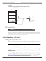
RFI considerations ............................................................................... 2-6
Outputting voltage and current ................................................................... 2-6
Setting voltage protection value ........................................................... 2-6
Selecting proper current range............................................................. 2-8
Selecting current limit mode ................................................................. 2-8
Editing output voltage and current limit values..................................... 2-9
Using the OPERATE key.................................................................... 2-11
Output bandwidth...................................................................................... 2-11
Output impedance .................................................................................... 2-12
Changing the battery channel’s output impedance ............................ 2-12
SCPI programming - outputting voltage and current ................................ 2-13
Command notes (outputting voltage and current) .............................. 2-14
Reading back V and I ............................................................................... 2-16
V and I display modes (Single or Dual) ............................................. 2-16
Measurement configuration................................................................ 2-16
SCPI programming — measure V and I, and DVM input ......................... 2-17
Command notes (measure V and I, and DVM input) ......................... 2-18
Independent voltage measurements (DVM) ............................................. 2-18
DVM input display mode .................................................................... 2-18
Measurement configuration................................................................ 2-19
SCPI programming - DVM ........................................................................ 2-19
Sink operation........................................................................................... 2-19
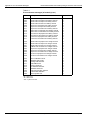
Table of Contents
Section
Model 2308 Portable Device Battery/Charger Simulator User’s Manual
Topic
Page
Programming examples ............................................................................
Outputting and reading back V and I ..................................................
DVM measurements ...........................................................................
Analog output ............................................................................................
3
2-21
2-21
2-21
2-22
Pulse Current Measurements.............................................................. 3-1
Overview ..................................................................................................... 3-2
Trigger level .......................................................................................... 3-2
Trigger delay......................................................................................... 3-3
Integration times ................................................................................... 3-3
Average readings count........................................................................ 3-4
Measurement configuration......................................................................... 3-4
Current range ....................................................................................... 3-5
Integration times ................................................................................... 3-5
Average readings count........................................................................ 3-5
Trigger delay and trigger level .............................................................. 3-6
Pulse current display mode .................................................................. 3-7
Pulse current measurement procedure....................................................... 3-7
No pulses detected ............................................................................... 3-8
Determining correct trigger level (pulse current)................................... 3-9
TRIG NOT DETECTED message....................................................... 3-11
SCPI programming - pulse current measurements ................................... 3-12
Command notes (pulse current measurements) ................................ 3-14
Using FAST, SEARch, and DETect..................................................... 3-16
Pulse current digitization ........................................................................... 3-19
Pulse current step method ........................................................................ 3-20
TLEV steps ......................................................................................... 3-21
Timeout setting ................................................................................... 3-25
Integration time ................................................................................... 3-25
Range with pulse current step ............................................................ 3-26
Programming examples ............................................................................ 3-26
Pulse current measurements.............................................................. 3-26
Pulse current digitization .................................................................... 3-27
Pulse current STEP method (battery channel only)............................ 3-27
4
Long Integration Measurements ........................................................ 4-1
Overview ..................................................................................................... 4-2
Integration time ..................................................................................... 4-3
Trigger edge ......................................................................................... 4-3
Trigger level .......................................................................................... 4-3
Pulse timeout ........................................................................................ 4-4
Measurement configuration......................................................................... 4-6
Current range ....................................................................................... 4-6
Integration time ..................................................................................... 4-6
Pulse timeout ........................................................................................ 4-7
Trigger edge and trigger level............................................................... 4-7
Long integration display mode.............................................................. 4-8
Long integration measurement procedure .................................................. 4-8
General notes ....................................................................................... 4-9
Determining correct trigger level (long integration)............................... 4-9
SCPI programming.................................................................................... 4-11
Command notes (long integration measurements)............................. 4-12
Using FAST, SEARch, and DETect..................................................... 4-12
Programming examples ............................................................................ 4-16
5
Relay Control .......................................................................................... 5-1
Overview .....................................................................................................
Connections ................................................................................................
Controlling relays ........................................................................................
SCPI programming......................................................................................
ii
5-2
5-3
5-4
5-5
2308-900-01 Rev. A / July 2008
Model 2308 Portable Device Battery/Charger Simulator User’s Manual
Section
6
Topic
Table of Contents
Page
GPIB Operation ....................................................................................... 6-1
Introduction ................................................................................................. 6-2
GPIB bus connections................................................................................. 6-2
Primary address .......................................................................................... 6-3
Setting the GPIB timeout for responses...................................................... 6-4
Long integration readings ..................................................................... 6-4
Pulse current readings.......................................................................... 6-4
MAV (Message Available Bit) ............................................................... 6-4
General bus commands .............................................................................. 6-5
REN (remote enable)............................................................................ 6-5
IFC (interface clear) .............................................................................. 6-6
LLO (local lockout)................................................................................ 6-6
GTL (go to local) ................................................................................... 6-6
DCL (device clear) ................................................................................ 6-6
SDC (selective device clear)................................................................. 6-6
GET (group execute trigger) ................................................................. 6-6
SPE, SPD (serial polling)...................................................................... 6-6
Front panel aspects of GPIB operation ....................................................... 6-6
Remote indicator and LOCAL key ........................................................ 6-7
Error and status messages................................................................... 6-7
Programming syntax ................................................................................... 6-7
Command words................................................................................... 6-7
Program messages............................................................................... 6-9
Response messages .......................................................................... 6-11
Message exchange protocol............................................................... 6-12
7
Status Structure ...................................................................................... 7-1
Overview ..................................................................................................... 7-2
Status byte and SRQ ............................................................................ 7-2
Status register sets ............................................................................... 7-2
Queues ................................................................................................. 7-2
Clearing registers and queues .................................................................... 7-3
Programming and reading registers............................................................ 7-4
Programming enable registers.............................................................. 7-4
Reading registers.................................................................................. 7-5
Status byte and service request (SRQ)....................................................... 7-5
Status byte register ............................................................................... 7-6
Service request enable register ............................................................ 7-7
Serial polling and SRQ ......................................................................... 7-7
Status byte and service request commands ......................................... 7-8
Status register sets...................................................................................... 7-8
Register bit descriptions ....................................................................... 7-8
Condition registers .................................................................................... 7-12
Event registers.................................................................................... 7-12
Event enable registers ........................................................................ 7-13
Queues...................................................................................................... 7-14
Output queue ...................................................................................... 7-15
Error queue......................................................................................... 7-15
Programming example - read error queue.......................................... 7-16
8
Common Commands ............................................................................ 8-1
Overview .....................................................................................................
IEEE-488.2 common commands and queries.............................................
*IDN? ....................................................................................................
*OPC.....................................................................................................
*SAV <NRf> and RCL <NRf> ...............................................................
*RST .....................................................................................................
*TRG.....................................................................................................
*TST?....................................................................................................
*WAI......................................................................................................
2308-900-01 Rev. A / July 2008
8-2
8-2
8-2
8-3
8-3
8-4
8-4
8-4
8-4
iii
Table of Contents
Section
9
Model 2308 Portable Device Battery/Charger Simulator User’s Manual
Topic
Page
Measurement Commands and
Optimizing Measurement Speed ........................................................ 9-1
Overview ..................................................................................................... 9-2
Command notes: Signal-oriented measurement commands
and queries ........................................................................................... 9-3
Optimizing measurement speed ................................................................. 9-5
Auto Zero State..................................................................................... 9-5
Programming examples........................................................................ 9-6
GPIB 488.1 protocol.................................................................................... 9-7
Selecting the 488.1 protocol ................................................................. 9-7
Protocol differences .............................................................................. 9-8
Trigger on talk both channels ...................................................................... 9-9
Bus commands ................................................................................... 9-10
Command notes ................................................................................. 9-10
Trigger continuous mode........................................................................... 9-10
Bus commands ................................................................................... 9-10
Command notes ................................................................................. 9-11
Using trigger continuous mode ........................................................... 9-11
Programming sequence example ....................................................... 9-11
10
DISPlay and FORMat ........................................................................... 10-1
DISPlay subsystem ...................................................................................
Command notes (SCPI commands - display).....................................
FORMat subsystem ..................................................................................
Command notes (SCPI commands - data format)..............................
10-2
10-2
10-4
10-5
11
SCPI Tables............................................................................................ 11-1
12
Performance Verification.................................................................... 12-1
SCPI command subsystems reference tables .......................................... 11-2
General notes ..................................................................................... 11-2
DISPlay command summary .............................................................. 11-3
FORMat command summary.............................................................. 11-4
OUTPut command summary .............................................................. 11-5
SENSe command summary .............................................................. 11-6
SOURce command summary ........................................................... 11-13
STATus command summary............................................................. 11-14
SYSTem command summary ........................................................... 11-15
Introduction ............................................................................................... 12-2
Verification test requirements.................................................................... 12-2
Environmental conditions.................................................................... 12-2
Warm-up period .................................................................................. 12-2
Line power .......................................................................................... 12-3
Recommended test equipment ................................................................. 12-3
Resistor connections .......................................................................... 12-3
Resistor considerations ...................................................................... 12-4
Verification limits ....................................................................................... 12-4
Example limits calculation................................................................... 12-4
Performing the verification test procedures............................................... 12-4
Test summary ..................................................................................... 12-4
Test considerations ............................................................................. 12-5
Output voltage accuracy ........................................................................... 12-5
Voltage readback accuracy ....................................................................... 12-7
Compliance current accuracy.................................................................... 12-8
Current readback accuracy ....................................................................... 12-9
5 A range readback accuracy ............................................................. 12-9
500 mA range readback accuracy .................................................... 12-10
50 mA range readback accuracy ...................................................... 12-12
5 mA range readback accuracy ........................................................ 12-13
Digital voltmeter input accuracy .............................................................. 12-15
iv
2308-900-01 Rev. A / July 2008
Model 2308 Portable Device Battery/Charger Simulator User’s Manual
Section
13
Topic
Table of Contents
Page
Calibration.............................................................................................. 13-1
Introduction ............................................................................................... 13-2
Environmental conditions .......................................................................... 13-2
Temperature and relative humidity...................................................... 13-2
Warm-up period .................................................................................. 13-2
Line power .......................................................................................... 13-2
Calibration considerations......................................................................... 13-2
Calibration cycle ................................................................................. 13-3
Recommended calibration equipment....................................................... 13-3
Resistor connections .......................................................................... 13-3
Resistor considerations ...................................................................... 13-3
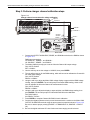
Front panel calibration............................................................................... 13-4
Step 1: Prepare the Model 2308 for calibration .................................. 13-4
Step 2: Perform battery channel calibration steps .............................. 13-5
Step 3: Perform charger channel calibration steps ............................. 13-9
Step 4: Enter calibration dates, and save calibration........................ 13-10
Remote calibration .................................................................................. 13-11
Remote calibration display................................................................ 13-11
Remote calibration procedure........................................................... 13-11
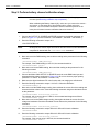
Step 1: Prepare the Model 2308 for calibration ................................ 13-11
Step 2: Perform battery channel calibration steps ............................ 13-12
Step 3: Perform charger channel calibration steps ........................... 13-13
Step 4: Program calibration date ...................................................... 13-14
Step 5: Save calibration constants and lock out calibration.............. 13-14
Changing the calibration code................................................................. 13-15
Changing the code from the front panel ........................................... 13-16
Changing the code by remote........................................................... 13-16
Resetting the calibration code .......................................................... 13-16
Viewing calibration date and count ......................................................... 13-17
Viewing date and count from the front panel .................................... 13-17
Acquiring date and count by remote ................................................. 13-17
Appendix
A
Topic
Page
Error and Status Messages ................................................................ A-1
Error and status message definitions ......................................................... A-2
B
Calibration Reference .......................................................................... B-1
Introduction ................................................................................................
Command summary ............................................................................
Miscellaneous commands..........................................................................
Detecting calibration errors ........................................................................
Reading the error queue......................................................................
Error summary .....................................................................................
Status byte EAV (Error Available) bit ...................................................
Generating an SRQ on error................................................................
Detecting calibration step completion ........................................................
Using the *OPC command...................................................................
Using the *OPC? query .......................................................................
Generating an SRQ on calibration complete .......................................
2308-900-01 Rev. A / July 2008
B-2
B-2
B-2
B-5
B-5
B-5
B-6
B-6
B-6
B-7
B-7
B-7
v
This page left blank intentionally .
List of Figures
Section
1
1
1
1
1
2
2
2
2
2
2
2
2
3
3
3
3
3
3
3
3
3
3
4
4
4
5
5
5
6
6
7
7
7
7
7
7
10
10
12
Figure
Figure 1-1
Figure 1-2
Figure 1-3
Figure 1-4
Figure 1-5
Figure 2-1
Figure 2-2
Figure 2-3
Title
Page
Model 2308 front panel ................................................................. 1-4
Model 2308 rear panel................................................................... 1-4
Simplified power supply diagram .................................................. 1-5
Model 2306-DISP Remote display option...................................... 1-6
Fuse drawer location .................................................................... 1-8
Battery channel preferred connection (maximum stability) ............ 2-3
Battery channel fastest transient response connection ................. 2-4
Charger channel 4-wire remote sense connection
from the DUT to the ouput ............................................................. 2-5
Figure 2-4 Local Sense Connections (battery channel and
charger channel)............................................................................ 2-6
Figure 2-5 Charger Control Circuit Testing.................................................... 2-19
Figure 2-6 Sink operation.............................................................................. 2-20
Figure 2-7 Preferred method ........................................................................ 2-20
Figure 2-8 Analog output Connections.......................................................... 2-22
Figure 3-1 Pulse current measurement........................................................... 3-2
Figure 3-2 Trigger delay for high pulse current measurement ........................ 3-3
Figure 3-3 Determining voltage and current characteristics for
battery channel .............................................................................. 3-9
Figure 3-4 Determining voltage and current characteristics for
charger channel .......................................................................... 3-10
Figure 3-5 PCURrent and SEARch time for pulse high measurement ......... 3-17
Figure 3-6 Sample pulse forms for step method ........................................... 3-22
Figure 3-7 Sample one-shot only pulses for step method............................. 3-22
Figure 3-8 Sample :STEP Pulse measurement ............................................ 3-23
Figure 3-9 Pulse form with rise and fall steps ............................................... 3-23
Figure 3-10 Pulse form with down steps first (600msec step duration) .......... 3-24
Figure 4-1 Steady state for waveforms based on low pulse times .................. 4-3
Figure 4-2 Long integration, search, and reading time comparison ................ 4-5
Figure 4-3 TOUT and search time ................................................................ 4-13
Figure 5-1 External source relay control ......................................................... 5-3
Figure 5-2 Internal source relay control .......................................................... 5-3
Figure 5-3 Relay connector (9-pin D-sub)....................................................... 5-4
Figure 6-1 IEEE-488 connector....................................................................... 6-2
Figure 6-2 Daisy chaining ............................................................................... 6-3
Figure 7-1 Status model structure ................................................................... 7-3
Figure 7-2 Status byte and service request..................................................... 7-6
Figure 7-3 Standard event status .................................................................... 7-9
Figure 7-4 Operation event status................................................................. 7-10
Figure 7-5 Measurement event status .......................................................... 7-11
Figure 7-6 Questionable event status ........................................................... 7-12
Figure 10-1 IEEE-754 single precision data format ........................................ 10-5
Figure 10-2 IEEE-754 double precision data format ....................................... 10-6
Figure 12-1 Connections for voltage verification tests .................................... 12-6
List of Figures
Section
12
12
12
12
12
13
13
13
13
vii
Model 2308 Portable Device Battery/Charger Simulator User’s Manual
Figure
Title
Page
Figure 12-2 Connections for output current and 5 A range current
verification tests ........................................................................... 12-8
Figure 12-3 Battery channel connections for 500 mA current
verification tests ......................................................................... 12-11
Figure 12-4 Battery channel connections for 50 mA current
verification tests ......................................................................... 12-12
Figure 12-5 Connections for 5 mA current verification tests.......................... 12-14
Figure 12-6 Charger channel connections for DVM accuracy verification..... 12-15
Figure 13-1 Battery channel connections for voltage calibration ................... 13-6
Figure 13-2 Connections for 5 A, 500 mA, and 50 mA current calibration ...... 13-7
Figure 13-3 Connections for 5 mA range calibration ....................................... 13-8
Figure 13-4 Charger channel connections for voltage calibration ................... 13-9
2308-900-01 Rev. A / July 2008
List of Tables
Section
Table
Title
Page
1
1
1
1
2
2
2
2
3
3
3
3
3
3
3
3
4
4
4
5
5
6
7
Table 1-1
Table 1-2
Table 1-3
Table 1-4
Table 2-1
Table 2-2
Table 2-3
Table 2-4
Table 3-1
Table 3-2
Table 3-3
Table 3-4
Table 3-5
Table 3-6
Table 3-7
Table 3-8
Table 4-1
Table 4-2
Table 4-3
Table 5-1
Table 5-2
Table 6-1
Table 7-1
7
7
Table 7-2
Table 7-3
7
7
7
7
8
8
9
9
9
9
10
10
11
11
11
11
11
Table 7-4
Table 7-5
Table 7-6
Table 7-7
Table 8-1
Table 8-2
Table 9-1
Table 9-2
Table 9-3
Table 9-4
Table 10-1
Table 10-2
Table 11-1
Table 11-2
Table 11-3
Table 11-4
Table 11-5
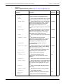
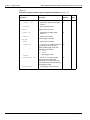
Display Modes ............................................................................... 1-9
Display mode examples............................................................... 1-10
Factory defaults (RST)................................................................. 1-11
Main MENU structure .................................................................. 1-13
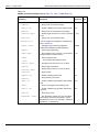
Current ranges............................................................................... 2-8
Output bandwidth channel setting ............................................... 2-11
SCPI command summary - outputting voltage and current ......... 2-13
SCPI commands: Measure V and I, and DVM input.................... 2-17
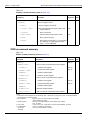
Current range and trigger level settings......................................... 3-6
TRIG NOT DETECTED message................................................ 3-11
SCPI commands - pulse current measurements ......................... 3-12
PCURrent FAST, SEARch, and DETect commands .................... 3-18
Setting UP and DOWN commands.............................................. 3-21
Trigger Level Setting.................................................................... 3-22
Sample TLEV values ................................................................... 3-23
Sample integration times ............................................................. 3-25
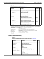
TRIG NOT DETECTED message................................................ 4-10
SCPI commands - long integration measurements ..................... 4-11
FAST, SEARch, and DETect command reference ....................... 4-14
Relay pinouts ................................................................................. 5-4
SCPI command - output relay control............................................ 5-5
General bus commands................................................................. 6-5
Common and SCPI commands - reset registers and
clear queues .................................................................................. 7-4
16-bit status register ...................................................................... 7-5
Common and SCPI Commands - status byte and
service request enable registers.................................................... 7-8
Common and SCPI commands - condition registers................... 7-12
Common and SCPI commands - event registers ........................ 7-13
Common and SCPI commands - event enable registers............. 7-13
SCPI Commands - error queue ................................................... 7-16
IEEE-488.2 common commands and queries ............................... 8-2
*OPC and *OPC? commands........................................................ 8-3
Signal-oriented measurement command summary ....................... 9-2
Trigger on talk bus commands..................................................... 9-10
Trigger continuous bus commands.............................................. 9-10
Trigger continuous mode programming example ........................ 9-11
SCPI commands - display ........................................................... 10-2
SCPI commands - data format .................................................... 10-4
DISPlay command summary ....................................................... 11-3
FORMat command summary....................................................... 11-4
OUTPut command summary ....................................................... 11-5
SENSe command summary ........................................................ 11-6
SOURce command summary .................................................... 11-13
List of Tables
Section
11
11
12
12
12
12
12
12
12
12
12
13
13
13
Model 2308 Portable Device Battery/Charger Simulator User’s Manual
Table
Title
Table 11-6
Table 11-7
Table 12-1
Table 12-2
Table 12-3
Table 12-4
Table 12-5
Table 12-6
Table 12-7
Table 12-8
Table 12-9
Table 13-1
Table 13-2
Table 13-3
STATus command summary ...................................................... 11-14
SYSTem command summary..................................................... 11-15
Recommended verification equipment......................................... 12-3
Output voltage accuracy limits ..................................................... 12-6
Voltage readback accuracy limits ................................................. 12-7
Compliance current accuracy limits ............................................. 12-9
5 A range current readback accuracy limits ............................... 12-10
500 mA range current readback accuracy limits ........................ 12-11
50 mA range current readback accuracy limits .......................... 12-13
5 mA range current readback accuracy limits ............................ 12-14
Digital voltmeter input accuracy limits ........................................ 12-16
Recommended calibration equipment.......................................... 13-3
Model 2308 front panel calibration summary ............................... 13-4
Remote calibration summary ..................................................... 13-14
Appendix Table
A
B
B
ix
Table A-1
Table B-1
Table B-2
Title
Page
Page
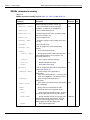
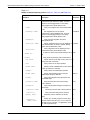
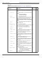
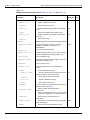
Error and status messages (all models)........................................ A-2
Remote calibration command summary........................................ B-2
Calibration errors........................................................................... B-6
2308-900-01 Rev. A / July 2008
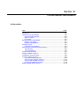
Section 1
Getting Started
In this section:
Topic
Page
Overview ..................................................................................................... 1-2
Applications................................................................................................. 1-2
Performance features ................................................................................. 1-2
Warranty information................................................................................... 1-2
Contact information..................................................................................... 1-2
Specifications .............................................................................................. 1-3
Inspection.................................................................................................... 1-3
Options and accessories............................................................................. 1-3
Power supply overview ............................................................................... 1-3
Remote display option ................................................................................ 1-5
Power-up..................................................................................................... 1-7
Line power connection ......................................................................... 1-7
Power-up sequence ............................................................................. 1-7
Fuse replacement................................................................................. 1-8
Display modes ............................................................................................ 1-8
Default settings ......................................................................................... 1-11
Setups - Save, Power-on, and Recall................................................. 1-12
Menu ......................................................................................................... 1-12
Getting around the MENU......................................................................... 1-14
SCPI programming ................................................................................... 1-15
Section 1: Getting Started
Model 2308 Portable Device Battery/Charger Simulator User’s Manual
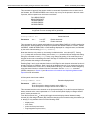
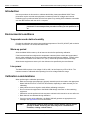
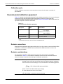
Overview
This manual describes Keithley Instruments Model 2308 Portable Device Battery/Charger
Simulator, which is designed specifically for development and high-speed production testing of DC
battery-operated products.
Applications
Development and high speed testing of DC battery-operated products, such as:
•
•
•
Cellular handsets
Cellular components like RFIC power amplifiers
Other high-volume precision electrical components.
Performance features
Key features and benefits include:
•
•
•
•
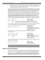
The Model 2308 is a specialized power supply that has a very fast recovery to large, near
instantaneous load current transitions. Conventional power supplies do not have this
capability. The Model 2308 is designed specifically to respond to large load changes and
very short pulsed loads with small transient voltage drop and a very fast recovery time.
Typical devices that have these types of characteristic loads are mobile phones, wireless
communication modules, and other portable, battery operated devices. The Model 2308 can
maintain a near-constant output, even under quickly-changing load conditions.
The power supply can measure a wide range of load currents. It can resolve down to 0.1 μA
and measure up to 5 A. It has fast measurement capability as well and can measure load
current pulses as narrow as 50 μsec.
The Model 2308 can simulate the output of a battery. Its programmable output resistance
can simulate a battery’s internal resistance so that the voltage output looks exactly like that
of a battery’s output.
The two channels can also sink current so that one channel (the battery channel) simulates
a discharged battery, while the other channel (the charger channel) can be used to simulate
a charger.
NOTE
Information contained in this section applies to all power supply channels
(unless otherwise noted). In this manual, Channel 1 refers to the battery
channel, Channel 2 refers to the charger channel.
Warranty information
Warranty information is located at the front of this manual. Should your power supply require
warranty service, contact the Keithley Instruments representative or authorized repair facility in
your area for further information. When returning the instrument for repair, be sure to fill out and
include the service form at the back of this manual to provide the repair facility with the necessary
information.
Contact information
If you have any questions after reviewing this information, please contact your local Keithley
representative or call one of our Applications Engineers at 1-800-348-3735 (U.S. and Canada
1-2
Return to Section Topics
2308-900-01 Rev. A / July 2008
Model 2308 Portable Device Battery/Charger Simulator User’s Manual
Section 1: Getting Started
only). A complete list of worldwide phone numbers are available on the Keithley Instruments
website at www.keithley.com.
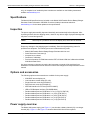
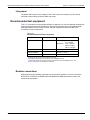
Specifications
Full Model 2308 specifications are included on the Model 2308 Portable Device Battery/Charger
Simulator Product Information CD-ROM. Check the Keithley Instruments website at
www.keithley.com for the latest updates to the specifications.
Inspection
The power supply was carefully inspected electrically and mechanically before shipment. After
unpacking all items from the shipping carton, check for any obvious signs of physical damage that
may have occurred during transit.
NOTE
There may be a protective film over the display lens, which can be removed.
Report any damage to the shipping agent immediately. Save the original packing carton for
possible future shipment. The following items are included with every order:
•
•
•
•
•
Model 2308 Portable Device Battery/Charger Simulator with line cord
Quick Disconnect Connector (2)
Accessories as ordered
Certificate of calibration
Product Information CD-ROM that contains PDFs of Model 2308 User’s Manual and Model
2308 Quick Start Guide
Any improvements or changes concerning the instrument or manual will be explained in an
addendum included with the manual. Be sure to note these changes and incorporate them into the
manual.
Options and accessories
The following options and accessories are available for the power supply.
•
•
•
•
•
•
•
•
•
•
•
2306-DISP remote display unit
Low inductance coaxial cable (SC-182)
Single fixed rack mount kit (P/N 4288-1)
Dual fixed rack mount kit (P/N 4288-2)
IEEE-488 Interface for PCI bus (P/N KPCI-488LP)
USB to GPIB adapter interface (P/N KUSB-488A)
Double shielded premium GPIB cable, 0.5 m (1.6 ft) (P/N 7007-05)
Double shielded premium GPIB cable, 1 m (3.2 ft) (P/N 7007-1)
Double shielded premium GPIB cable, 2 m (6.5 ft) (P/N 7007-2)
Double shielded premium GPIB cable, 3 m (10 ft) (P/N 7007-3)
Double shielded premium GPIB cable, 4 m (13 ft) (P/N 7007-4)
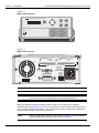
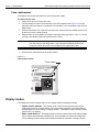
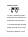
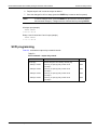
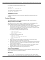
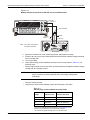
Power supply overview
The Model 2308 power supply (see Figure 1-1) can simulate a battery channel (#1) or a charger
channel (#2). Figure 1-1 and Figure 1-2 show the Model 2308 front and rear panels.
2308-900-01 Rev. A / July 2008
Return to Section Topics
1-3
Section 1: Getting Started
Model 2308 Portable Device Battery/Charger Simulator User’s Manual
Figure 1-1
Model 2308 front panel
LOCAL
2308 Portable Device Battery/Charger Simulator
MENU
OPERATE
ENTER
SET
DISPLAY
POWER
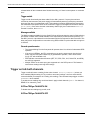
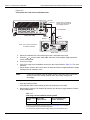
Figure 1-2
Model 2308 rear panel
WARNING:NO INTERNAL OPERATOR SERVICABLE PARTS,SERVICE BY QUALIFIED PERSONNEL ONLY.
OUTPUT #1
SOURCE
+
+
SENSE
+ _
SOURCE
_
_
ANALOG
OUT
mA
A
(5/50) (0.5/5)
OUTPUT #2
SOURCE
+
+
SENSE
+ _
SOURCE
_
_
DVM IN
-30 VDC MAX
DVM IN
_
+
ISOLATION FROM EARTH: 22 VOLTS MAX MAX.
LINE FUSE
SLOWBLOW
2.0A, 250V
RELAY
CONTROL
LINE RATING
100-120VAC, 200-240VAC
50, 60 HZ 165VA MAX
24VDC MAX
IEEE-488
(ENTER IEEE ADDRESS
FROM FRONT PANEL MENU)
REMOTE
DISPLAY
OPTION
MADE IN
U.S.A.
CAUTION:FOR CONTINUED PROTECTION AGAINST FIRE HAZARD,REPLACE FUSE WITH SAME TYPE AND RATING.
NOTE
The output from each channel is isolated from the other channel.
CAUTION
Allow for adequate ventilation around the front and rear-panel openings to
prevent the unit from overheating which may degrade performance.
Make sure that the maximum combined channel output is not exceeded (see complete
Specifications at www.keithley.com). Also, do not exceed 3 A when using the power supply as a
sink. For output voltages exceeding 5 V, the maximum sink current is less than 3 A (derate the
maximum sink current 0.2 A for each volt over 5 V).
NOTE
1-4
When using the power supply as a sink (negative polarity), the power supply is
dissipating rather than sourcing power (see Sink operation).
Return to Section Topics
2308-900-01 Rev. A / July 2008
Model 2308 Portable Device Battery/Charger Simulator User’s Manual
Section 1: Getting Started
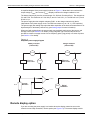
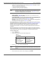
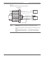
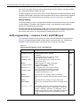
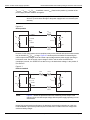
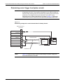
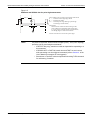
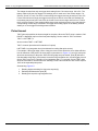
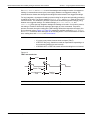
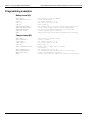
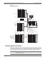
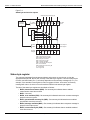
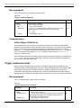
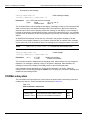
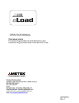
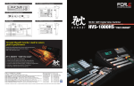
A simplified diagram of the power supply is shown in Figure 1-3. Note that it can read back the
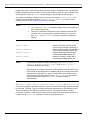
output voltage (Vmeter) and current (Imeter). Display resolution for voltage readback is 1mV.
The battery channel (#1) has four current ranges: 5 A, 500 mA, 50 mA and 5 mA. The charger has
5 A and 5 mA. The resolution on 5 A is 100 μA, and on 5 mA is 0.1 μA. The 500 mA is 10 μΑ and
50 mA is 1μΑ.
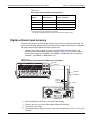
The power supply also has a digital voltmeter (DVM - on the charger channel only) that is
independent of the power supply circuit. The DVM can measure up to +30 V (1 mV resolution).
The power supply has analog output pins that allow acquisition of the load current waveform for indepth analysis on the battery channel only (see Analog output for more information).
When used with a pulsed load, the power supply can read back peak current, idle current, and
average current (see Section 3 for details). A long integration (up to 60 seconds) function is
provided to measure average current of a low frequency pulse (long period) or a series of pulses
(see Section 4 for details).
Figure 1-3
Simplified power supply diagram
Battery Channel
(Channel #1)
+
I meter
Source
Charger Channel
(Channel #2)
V-Source
with I-Limit
V meter
Source
V-Source
with I-Limit
_
V meter
_
+
5/50mA
Shunt
+
I meter
Current
Monitors
DVM
Digital
Voltmeter
0.5/5A
_
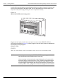
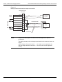
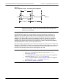
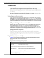
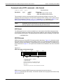
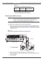
Remote display option
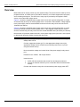
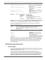
If you are mounting the power supply in a location where the display cannot be seen or the
controls are not easily accessible, use this option (see Figure 1-4). This remote display module
2308-900-01 Rev. A / July 2008
Return to Section Topics
1-5
Section 1: Getting Started
Model 2308 Portable Device Battery/Charger Simulator User’s Manual
includes all front-panel instrument controls/features (with the exception of power). All features and
menus work as described for the Model 2308. A 9-foot cable attaches the remote display to the
rear-panel of the power supply, allowing the unit to be operated remotely.
Figure 1-4
Model 2306-DISP Remote display option
2306-DISP RE
MOTE DISPLA
Y
OPERATE
LOCAL
MENU
SET
DISPLAY
ENTER
Plug the remote display module into the rear-panel connector labeled REMOTE DISPLAY
OPTION (see rear panel in Figure 1-2). When plugged in, the main display module is disabled with
the following message displayed:
REMOTE PANEL
ENABLED
When the remote display module is unplugged, control returns to the main display module.
NOTE
When using the remote display, VFD BRIGHTNESS may not appear in the main
menu (dependent on the firmware revision in the unit).
When connecting or disconnecting the remote display, allow a few seconds for
the power supply to recognize the action. Fast, repeated connects/disconnects
of the remote display may cause the power supply to hang or appear to hang.
Disconnecting the remote display and waiting a few seconds to reconnect it may
clear the problem. If not, cycling power on the power supply clears the condition.
1-6
Return to Section Topics
2308-900-01 Rev. A / July 2008
Model 2308 Portable Device Battery/Charger Simulator User’s Manual
Section 1: Getting Started
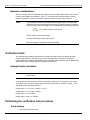
Power-up
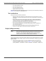
Line power connection
The power supply operates from a line voltage in the range of 100-120VAC/200-240VAC at a
frequency of 50 or 60 Hz, 165 V AC. Line voltage and frequency are automatically sensed,
therefore there are no switches to set. Check to see that the line power in your area is compatible.
Use the :SYSTem::LFRequency? query (see Section 10) to read the line frequency.
NOTE
See complete Specifications at www.keithley.com for the operating environment
requirements of the equipment before power-up.
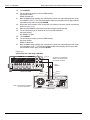
Perform the following steps to connect the power supply to the line power and turn it on:
WARNING
1.
2.
3.
The power cord supplied with the Model 2308 contains a separate ground
for use with grounded outlets. When proper connections are made,
instrument chassis is connected to power line ground through the ground
wire in the power cord. Failure to use a grounded outlet may result in
personal injury or death due to electric shock.
Before plugging in the power cord, make sure the front-panel power switch is in the off (0)
position.
Connect the female end of the supplied power cord to the AC receptacle on the rear panel.
Turn on the power supply by pressing the front-panel power switch to the on (1) position.
Power-up sequence
On power-up, the power supply performs self-tests on its RAM and EPROM. After a blinking cursor
appears on line one, RAM tests are completed. After a blinking cursor appears on line two,
EPROM self tests are completed.
NOTE
If a problem develops while the instrument is under warranty, return it to Keithley
Instruments for repair.
If the instrument passes the self tests, the following information is briefly
displayed:
•
•
Top Line - The model number and the IEEE-488 address are displayed
(The factory default GPIB address is 16).
Bottom Line - Firmware revision levels are displayed for the main board
and the display board. Also displayed is the detected line frequency.
After displaying the above information, any errors that occurred during the startup sequence will be
displayed. Then, the instrument goes to the default settings (*RST) or saved power-up settings
(SAV0-3) with the output off (see Default settings). Any missed error messages may be viewed
over the bus using the :SYST:ERR? command (see Error queue).
2308-900-01 Rev. A / July 2008
Return to Section Topics
1-7
Section 1: Getting Started
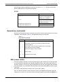
Model 2308 Portable Device Battery/Charger Simulator User’s Manual
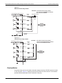
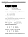
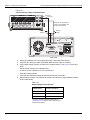
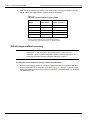
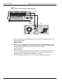
Fuse replacement
A rear-panel fuse protects the power line input of the power supply.
To replace the line fuse:
1.
2.
3.
4.
Power off the unit and remove line cord.
The fuse drawer is located on the left side of the AC receptacle (see Figure 1-5). On the
right side of the fuse drawer is a small tab. At this location, use a screwdriver to pry the fuse
drawer open.
Slide the fuse drawer out to gain access to the fuse. Note that the fuse drawer does not pull
all the way out of the power module.
Snap the fuse out of the drawer and replace it with the same type (250 V, 2.0 A, 5 × 20 mm
time lag). The Keithley Instruments part number is FU-81.
CAUTION
5.
For continued protection against fire or instrument damage, only replace the
fuse with the type and rating listed. If the instrument repeatedly blows fuses,
locate and correct the cause of the problem before replacing the fuse.
Push the fuse drawer back into the power module.
Figure 1-5
Fuse drawer location
Fuse drawer
Y QUALIFIED PERSONNEL ONLY.
OUTPUT #2
SOURCE
+
+
SENSE
+ _
SOURCE
_
_
DVM IN
-30 VDC MAX
DVM IN
_
+
RTH: 22 VOLTS MAX MAX.
LINE FUSE
SLOWBLOW
2.0A, 250V
LINE RATING
100-120VAC, 200-240VAC
50, 60 HZ 165VA MAX
REMOTE
DISPLAY
OPTION
USE WITH SAME TYPE AND RATING.
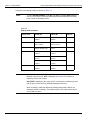
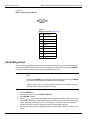
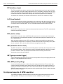
Display modes
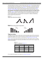
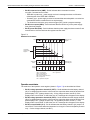
For voltage and current readings, there are five display modes described as follows:
•
•
1-8
SINGLE V AND I DISPLAY - This display mode is used to read back the actual output
voltage and current on a single channel. The active channel dictates if the single channel
being displayed is for the battery or charger channel. This display mode is the RST default
(see Section 2 for details).
DUAL V AND I DISPLAY - This display mode is used to read back the actual output voltage
and current for both channels simultaneously. The top display line shows the voltage and
current readings for the battery channel while the bottom line shows the charger channel
Return to Section Topics
2308-900-01 Rev. A / July 2008
Model 2308 Portable Device Battery/Charger Simulator User’s Manual
Section 1: Getting Started
readings. The # symbol indicates the active channel (see Section 2 for details). For both
channels, the output state is indicated by:
• 0 (zero) if the output is OFF for that channel.
• l (lowercase L) if the output is ON for that channel..
NOTE
•
•
•
With DUAL V AND I DISPLAY mode enabled, there is no indicator on the front
panel about voltage protection or current limit state. See Section 2 for more
information on voltage protection and current limit.
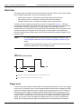
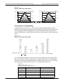
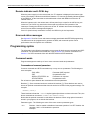
PULSE CURRENT - This mode is used to display high, low, or average pulse-current
measurements (see Section 3 for details)
LONG INTEGRATION - This mode is used to display average current measurements of a
pulse or pulses measuring periods between 850 msec to 60 sec (60 Hz line frequency) and
840 msec to 60 sec (50 Hz line frequency) (see Section 4 for details).
DVM INPUT (charger channel only) - This mode is used to display the DC voltage applied to
the DVM input of the power supply (see Section 2 for details).
Use the SAVE SETUP item of the MENU to save the selected display mode in memory, and use
the POWER ON SETUP item to specify the power-on setup (Setups - Save, Power-on, and Recall
for details). The Dual V and I display cannot be saved. A reset will not change this setting.
Recalling a setup may change the setting. If setup recalling has a channel function set to
something other than voltage or current then this setting is disabled otherwise the setting is left
unchanged.
Selecting (enabling) Dual V and I will switch the function to voltage for each channel unless the
function is already voltage or current. Dual V and I will be disabled if you change the display mode
on either channel to be Pulse Current, Long Integration, or DVM Input (Channel #2 only).
To select a display mode:
1.
2.
Press the DISPLAY key.
Press the ▲ or ▼ keys to scroll to the desired display mode.
Press the
NOTE
4.
Battery channel (#1)
Charger channel (#2)
•
•
•
•
•
•
•
•
•
SINGLE V AND I
DUAL V AND I
LONG INTEGRATION
PULSE CURRENT
or
▲
3.
▲
Table 1-1
Display Modes
SINGLE V AND I
DUAL V AND I
LONG INTEGRATION
PULSE CURRENT
DVM INPUT
keys to select Channel #1 or #2.
Switching back to the original active channel will display the initial setting for that
channel.
With the desired mode and active channel displayed, press ENTER.
2308-900-01 Rev. A / July 2008
Return to Section Topics
1-9
Section 1: Getting Started
Model 2308 Portable Device Battery/Charger Simulator User’s Manual
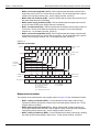
Examples of the display modes are shown in Table 1-2.
NOTE
To select PULSE CURRENT high (HI), low (LO) or average (AVG) readings,
use the ▲ or ▼ keys to select the desired pulse measurement after selecting
pulse current as the display mode.
Table 1-2
Display mode examples
Display mode
Samples for battery
channel (#1)
Samples for charger
channel (#2)
Reference
SINGLE V AND I:
6.116V #1 ON
6.116 V #2 ON
Section 2
1.2058 A
1.2058 A
2.97V 25.7m 1#
2.97V 25.7m 1
0.00V 0.00A 0
1.00V 0.17A 1#
DVM input:
N/A
(charger channel only)
DVM INPUT #2 OFF
5.321 V
Section 2
Pulse current:
PULSE HI #1 ON
PULSE HI #2 ON
Section 3
2.1947 A
2.1947 A
PULSE LO #1 ON
PULSE LO #2 ON
0.2147 A
0.2147 A
PULSE AVG #1 ON
PULSE AVG #2 ON
1.1495 A
1.1495 A
LONG INT #1 ON
LONG INT #2 ON
1.0236 A
1.0236 A
DUAL V AND I:
Long integration:
NOTE
Section 2
Section 4
#1 or #2 indicates the active channel. ON indicates that the output is turned on.
With the output turned off, OFF is displayed (see Section 2 for details on
outputting current and voltage).
NO PULSE is displayed if the output is OFF or pulses are not detected (output
ON) for pulse current and long integration display modes only.
When a change is made that affects the readings being taken, dashes are
displayed instead of readings. The dashes remain until a valid reading for the
new condition is taken.
1-10
Return to Section Topics
2308-900-01 Rev. A / July 2008
Model 2308 Portable Device Battery/Charger Simulator User’s Manual
Section 1: Getting Started
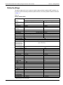
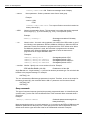
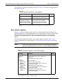
Default settings
The power supply can be set to power-on with the factory default conditions (RST defaults) or to
one of four user-saved setup conditions (SAV0 to SAV3). The factory default conditions are listed
in Table 1-3.
Table 1-3
Factory defaults (RST)
Reset (RST) default
Setting
Output value
settings:
Voltage (V)
Current (A)
Output state
(operate)
Voltage protection
Display type
GPIB address*
Current range
Integration rate
Average readings
Power on setup*
Current limit mode
Auto Zero State
Output relay one*
Output relay two*
Output relay three*
Output relay four*
VFD brightness*
Output bandwidth
Output impedance
Pulse current:
High time
Low time
Average time
Digitize time
Timeout
Average readings
Trigger delay
Trigger level:
Step
Step Initial
Step Sequence
Step Length
Step Skip
Step up
Step down
Step time
Step timeout
Step delay
Long integration:
Integration time
Battery channel (#1)
Charger channel (#2)
0.000V
0.2500A
OFF
0.000V
0.2500A
OFF
8 V, clamp off
Single V and I
5 A (Auto Range OFF)
1.00 PLC
1
LIM
Over bus: 1
8 V, clamp off
Single V and I
No effect (factory set to 16)
5 A (Auto Range OFF)
1.00 PLC
1
No effect (factory set to RST)
LIM
ON (applies to both channels)
No effect (after power
cycle, set to zero)
From display: FULL BRIGHTNESS
LOW
0.00 Ω
LOW
Not Applicable
33 µsec
33 µsec
33 µsec
33 µsec
1.000 sec
1
0.00000 sec
0
Off
2 sec
0
0
0
1
1
200µs
2ms
0
33 µsec
33 µsec
33 µsec
33 µsec
1.000 sec
1
0.00000 sec
0
1 second
1 second
**Global settings (not channel-specific).
2308-900-01 Rev. A / July 2008
Return to Section Topics
1-11
Section 1: Getting Started
Model 2308 Portable Device Battery/Charger Simulator User’s Manual
Table 1-3
Factory defaults (RST)
Reset (RST) default
Setting
Pulse timeout
Trigger edge
Trigger level
Battery channel (#1)
Charger channel (#2)
16 seconds
16 seconds
RISING
RISING
Same as “Trigger level” under Pulse Current
Same as “Trigger level” under
(above)
Pulse Current (above)
**Global settings (not channel-specific).
Setups - Save, Power-on, and Recall
Setups are configured by SAVE SETUP, POWER ON SETUP and RECALL SETUP items of the
MENU (which is accessed by pressing the MENU key). When a setup is saved, all settings that are
channel-specific settings will be saved to that setup. Saving/recalling a setup has no effect on
Global Settings (see Global settings in Table 1-3). Similarly, recalling a setup loads only the
channel-specific parameters from that setup.
NOTE
Table 1-4 shows the menu structure. Rules to navigate the menu follow the
table.
The setup MENU items are explained as follows:
•
•
•
SAVE SETUP - Save the present power supply setup to a memory location;
SAV0-SAV3.
RECALL SETUP - Return the power supply to the RST defaults (Table 1-3), or to one of
four user-saved setups; RST, SAV0-SAV3.
POWER-ON SETUP - Select the setup to use at power-up; RST, SAV0-SAV3.
When powering up or recalling the SAV0, SAV1, SAV2, or SAV3 setup, the output will be OFF
regardless of the operate state when the setup was saved. For example, if the output is ON when
the setup is saved as SAV0, the power supply will power up with the output OFF for the SAV0
power-on setup.
NOTE
For GPIB operation, the setups are saved and recalled using the *SAV, *RCL,
and *RST commands (see Section 8 or details). The power-on setup is
selected using the SYSTem:POSetup command (see Section 10).
Menu
Many aspects of operation are configured from the menus summarized in Table 1-4. Use the rules
following the table to navigate through the menu structure.
NOTE
1-12
The menu key is used to access the menu structure. However, if in remote for
IEEE-488 bus operation (“R” displayed below “ON/OFF”) the menu key returns
the instrument to LOCAL operation.
Return to Section Topics
2308-900-01 Rev. A / July 2008
Model 2308 Portable Device Battery/Charger Simulator User’s Manual
Section 1: Getting Started
Table 1-4
Main MENU structure
Menu item
Description
Ref
GPIB ADDRESS
CURRENT RANGE #1/#2
Set primary address (0 to 30)
Select current range:
Battery channel (#1)
Charger channel (#2)
5A
5A
500 mA
5 mA
50 mA
AUTO
5 mA
AUTO
Set integration rate in NPLC (0.002 to 10)
Set average reading count (1 to 10)
Save present setup in memory (SAV0–SAV3)
Recall setup from memory (RST, SAV0–SAV3).
Select power-on setup (RST, SAV0–SAV3)
Calibrate unit (see Calibration)
Set voltage protection range (0–8 V) and clamp (ON/OFF)
Select current limit mode (LIMit or TRIP)
Set auto zero state (ON/OFF)
Close (1) or open (0) relay control circuitry
Display firmware revision levels
Display serial number of the power supply
Set VFD display’s brightness level (OFF, FULL, 3/4, 1/2, 1/4)
Set bandwidth (HIGH, LOW)
Set battery channels impedance (0–1 Ω)
Pulse-current configuration.
Set high time integration rate (in µsec.).
Set low time integration rate (in µsec.).
Set average time integration rate (in µsec.).
Set pulse integration rates automatically.
Set pulse timeout (default is 1.000 second, incremented in
1ms steps)
Set average reading count (1 to 100).
Set trigger delay in seconds (0 to 100 msec).
Sets pulse current trigger level in Amps for the 5 A, 500 mA,
50 mA, or 5 mA current ranges:
Battery channel (#1)
Charger channel (#2)
A(5.0) 0–5A in 5 mA steps
A(5.0) 0–5 A in 5 mA steps
mA(500) 0–500 mA in 0.5 mA steps
mA (50) 0-50 mA in 0.05 mA steps
mA (5) 0-5 mA in 0.005 mA steps
Sect. 6
Sect. 2
NPLC RATE #1/#2
AVER READINGS #1/#2
SAVE SETUP
RECALL SETUP
POWER ON SETUP
CALIBRATE UNIT
VOLT PROTECT #1/#2
CURR LIM MODE #1/#2
AUTO ZERO STATE
OUTPUT RELAYS
REVISION NUMBER
SERIAL NUMBER
VFD BRIGHTNESS
OUT BANDWIDTH #1/#2
OUT IMPEDANCE #1
PULSE CURRENT #1/#2
HIGH TIME
LOW TIME
AVERAGE TIME
AUTO TIME
PULSE TIMEOUT
AVERAGE READINGS
TRIGGER DELAY
TRIGGER LEVEL
Sect. 2
Sect. 2
Note 1
Note 1
Note 1
Sec. 13
Sect. 2
Note 2
Sect. 9
Sect. 5
Note 2
Note 3
Sect. 10
Sect. 2
Sect. 2
Sect. 3
The main menu structure is accessed by pressing the MENU key on the front panel.
Notes:
1. See Default settings in this section to save and recall setups.
2. Revision Number displays the firmware revision level for the microcontroller and the display.
3. Serial Number displays the serial number of the power supply.
2308-900-01 Rev. A / July 2008
Return to Section Topics
1-13
Section 1: Getting Started
Model 2308 Portable Device Battery/Charger Simulator User’s Manual
Table 1-4
Main MENU structure
Menu item
Description
Ref
LONG INTEGRAT #1/#2
INTEGRATION TIME
AUTO TIME
PULSE TIMEOUT
TRIGGER EDGE
TRIGGER LEVEL
Long integration configuration.
Sect. 4
Manually set integration time (up to 60 sec).
Automatically set integration time.
Set the “NO PULSE” timeout period (1 to 63 sec).
Select trigger edge (rising, falling, or neither).
Sets long integration trigger level in Amps for the 5 A, 500 mA,
50 mA, or 5 mA current ranges:
Battery channel (#1)
Charger channel (#2)
A (5.0) 0–5 A in 5 mA steps
A (5.0) 0–5 A in 5 mA steps
mA (500) 0–500 mA in 0.5 mA steps
mA (50) 0-50 mA in 0.05 mA steps
mA (5) 0-5 mA in 0.005 mA steps
The main menu structure is accessed by pressing the MENU key on the front panel.
Notes:
1. See Default settings in this section to save and recall setups.
2. Revision Number displays the firmware revision level for the microcontroller and the display.
3. Serial Number displays the serial number of the power supply.
Getting around the MENU
▲
Press the MENU key to activate the menu.
Press the ▲ or ▼ keys to scroll through the primary menu items.
Press the or keys to toggle between Channel #1 and Channel #2.
▲
•
•
•
▲
▲
•
▲
•
The active channel may be changed in the main menu, and the top submenus for pulse
current and long integration. The active channel cannot be changed in all other submenus.
Select the displayed primary menu item by pressing ENTER. With PULSE CURRENT or
LONG INTEGRATION selected, use the ▲ or ▼ keys to display the secondary items (again,
pressing ENTER selects the displayed item).
▲
▲
▲
▲
Display and change settings and selections (for a menu item) using the edit keys
( ▲, ▼, , or keys):
– For a setting, use or
keys to place the cursor on the desired digit, then use the ▲ or
▼ keys to increase or decrease the value (unless noted otherwise).
– Rapid jump to minimum or maximum: To rapidly jump to the maximum value, increment
the most significant digit (the left further-most digit in the selection setting). If the most
▲
1-14
▲
Before pressing enter, make sure the desired channel is active. If ENTER is
pressed with the incorrect channel selected, press the MENU key (to cancel
changes), use the
or
keys to scroll to the desired channel, and then press
ENTER to select the displayed primary menu item.
NOTE
•
▲
If a channel number is not shown, the or
keys presses will be ignored. Also
the
or
keys presses will be ignored if a submenu only exists on the battery
channel (not on the charger channel).
NOTE
Return to Section Topics
2308-900-01 Rev. A / July 2008
Model 2308 Portable Device Battery/Charger Simulator User’s Manual
Section 1: Getting Started
▲
significant digit is not displayed, place the cursor on that digit’s menu location and
increment from there. To rapidly jump to the minimum value, decrement the most
significant digit menu location. To find the most significant digit for a setting, press the
key until the cursor stops moving.
– For a selection, use the ▲ or ▼ keys to scroll to the desired option (unless noted
otherwise).
With the desired setting or selection displayed, press ENTER for it to take effect. Pressing
MENU will cancel the edit operation.
Use the MENU key to exit the MENU structure.
•
•
SCPI programming
SCPI programming information is integrated with front-panel operation throughout this manual.
SCPI commands are listed in tables, and additional information that pertains exclusively to remote
operation is provided after each table. Also, the SCPI tables may reference other sections of this
manual.
Except for Section 11, all SCPI tables in this manual are abridged. That is, they exclude most
optional command words and query commands. Optional command words and query commands
are summarized as follows.
Optional Command Words - In order to be in conformance with the IEEE-488.2 standard, the
power supply accepts optional command words. Any command word that is enclosed in brackets
( [ ] ) is optional and does not have to be included in the program message.
Query Commands - Most command words have a query form (exceptions are noted). A query
command is identified by the question mark (?) that follows the command word. A query command
requests (queries) the programmed status of that command. When a query is sent and the power
supply is addressed to talk, the response message is sent to the computer.
To send a SCPI command as a query, append a “?” to the fundamental form of the command
(make sure to add the “?” immediately following the command on the same line). For complete
details, see Programming syntax.
2308-900-01 Rev. A / July 2008
Return to Section Topics
1-15
This page left blank intentionally .
Section 2
Basic Power Supply Operation
In this section:
Topic
Page
Test connections ........................................................................................ 2-2
Remote sense ...................................................................................... 2-5
Local sense .......................................................................................... 2-5
RFI considerations ............................................................................... 2-6
Outputting voltage and current.................................................................... 2-6
Setting voltage protection value ........................................................... 2-6
Selecting proper current range ............................................................. 2-8
Selecting current limit mode ................................................................. 2-8
Editing output voltage and current limit values ..................................... 2-9
Using the OPERATE key.................................................................... 2-11
Output bandwidth...................................................................................... 2-11
Output impedance..................................................................................... 2-12
Changing the battery channel’s output impedance ............................ 2-12
SCPI programming - outputting voltage and current................................. 2-13
Command notes (outputting voltage and current) .............................. 2-14
Reading back V and I................................................................................ 2-16
V and I display modes (Single or Dual) ............................................. 2-16
Measurement configuration ................................................................ 2-16
SCPI programming — measure V and I, and DVM input.......................... 2-17
Command notes (measure V and I, and DVM input).......................... 2-18
Independent voltage measurements (DVM) ............................................. 2-18
DVM input display mode .................................................................... 2-18
Measurement configuration ................................................................ 2-19
SCPI programming - DVM ........................................................................ 2-19
Sink operation ........................................................................................... 2-19
Programming examples ............................................................................ 2-21
Outputting and reading back V and I .................................................. 2-21
DVM measurements........................................................................... 2-21
Analog output............................................................................................ 2-22
Section 2: Basic Power Supply Operation
Model 2308 Portable Device Battery/Charger Simulator User’s Manual
Test connections
WARNING
When installing a unit into a test system, make sure the external power
sources do not apply voltage to the power supply in excess of its
maximum limits (see complete Specifications at www.keithley.com). Failure
to do so could result in personal injury or death.
The source and measurement connections are provided with overvoltage
protection rated up to 500 V for 50 µs. Do not connect sources that
produce transient voltages greater than 500 V or the protection provided
by the equipment may be degraded.
Test connections to the power supply are made at the rear panel using a quick disconnect
connector (see rear panel in Figure 1-1 for connector location). Use up to #14 AWG wire for the
screw terminals of the connector. Once the connector is wired up, plug it into the rear panel and
tighten the captive retaining screws.
Figure 2-1 and Figure 2-2 show optimum remote 4-wire connections for device-under-test (DUT)
preferred connection (Figure 2-1) and fastest transient response connection (Figure 2-2).
2-2
Return to Section Topics
2308-900-01 Rev. A / July 2008
Model 2308 Portable Device Battery/Charger Simulator User’s Manual
Section 2: Basic Power Supply Operation
Figure 2-1
Battery channel preferred connection (maximum stability)
Quick Disconnect
Connector
Analog
Outputs
(0.5A/5A)
(5mA/50mA)
1A/V
/V
Oscilloscope
or
Digitizer
10mA
Source -
Internal
Source -
Load Test Leads
Sense Sense +
DUT
Source +
Source +
Twisted Pair
NOTE
Twist source leads together and twist sense leads together for optimum
performance.
The analog outputs provide a voltage output based on the measured current as
follows:
0.5/5 A Output referenced to Source - : 1 A/V (each volt out represents 1A)
5/50 mA Output referenced to Source - : 10 mA/V (each volt out represents
10 mA)
2308-900-01 Rev. A / July 2008
Return to Section Topics
2-3
Section 2: Basic Power Supply Operation
Model 2308 Portable Device Battery/Charger Simulator User’s Manual
Figure 2-2
Battery channel fastest transient response connection
Quick Disconnect
Connector
Analog
Outputs
(0.5A/5A)
(5mA/50mA)
1A/V
/V
Oscilloscope
or
Digitizer
10mA
Source -
Internal
Source -
Load Test Leads
Sense Sense +
DUT
Source +
Source +
Twisted Pair
NOTE
Twist source leads together and twist sense leads together for optimum
performance.
The analog outputs provide a voltage output based on the measured current as
follows:
0.5/5 A Output referenced to Source - : 1 A/V (each volt out represents 1A)
5/50 mA Output referenced to Source - : 10 mA/V (each volt out represents
10 mA)
2-4
Return to Section Topics
2308-900-01 Rev. A / July 2008
Model 2308 Portable Device Battery/Charger Simulator User’s Manual
Section 2: Basic Power Supply Operation
Figure 2-3
Charger channel 4-wire remote sense connection from the DUT to the ouput
Quick Disconnect
Connector
DVM Input
External Test Circuit
DVM +
+
DVM -
-
Source Source Sense Sense +
DUT
Source +
Source +
Model 2308
Source Input/Output
NOTE
Twisted Pair
Twist Source leads together and twist Sense leads together for
optimum performance.
Remote sense
As shown in Figure 2-1 the Model 2308 battery and charger channels are intended to be operated
with remote sense leads (4 wire connection). The Sense+ and Sense- pins provide output voltage
sensing. Without these terminals connected, the power supply operates without voltage feedback
and therefore supplies an unregulated voltage. This unregulated voltage value can be up to +18 V
or down to -5 V. Use voltage protection to turn off the output and protect against the extremes
(refer to Setting voltage protection value).
Connect the sense inputs to the supply as close as possible to the load’s source inputs through
twisted pair leads (refer to Figure 2-1). This is necessary to achieve the maximum transient
performance of the supply.
CAUTION
Do NOT connect the sense inputs and supply outputs at the rear of the supply!
Connecting the sense leads in this fashion will severely compromise the
performance of Model 2308 with dynamic loads when using 4-wire sense.
Local sense
The Model 2308 battery and charger channels can be connected to operate with local sense leads
(2-wire connection) as shown in Figure 2-4. In this connection scheme, the sense inputs and
supply outputs are connected at the rear of the supply.
2308-900-01 Rev. A / July 2008
Return to Section Topics
2-5
Section 2: Basic Power Supply Operation
Model 2308 Portable Device Battery/Charger Simulator User’s Manual
Figure 2-4
Local Sense Connections (battery channel and charger channel)
Quick Disconnect
Connector
Source Source Sense DUT
Sense +
Source +
Source +
Twisted Pair
RFI considerations
NOTE
Twist Source leads together for optimum performance.
Operating the power supply in high Radio Frequency Interference (RFI) environments may result
in improper operation. For that reason, keep RFI to a minimum when operating the unit. Additional
shielding can be used to reduce RFI to an acceptable level.
Outputting voltage and current
Setting voltage protection value
NOTE
The voltage protection value (VPT) is channel-specific. The number after the
number sign (#) indicates the channel affected by editing.
Voltage protection value (VPT) is provided for the battery and charger channels. This function
monitors the SOURCE + pins (see Figure 2-1 or Figure 2-4) with respect to the Model 2308’s
internal ground and will shut off the output voltage for either channel when the protection voltage
range (which equals the set voltage ± protection voltage) set by the user is exceeded. This voltage
is typically not the same voltage as at the device under test due to lead impedance and internal
sense resistor losses.
The VPT message will appear on the lower line of the display after the current reading indicator (A
or mA). The message will clear when the output it turned back ON, unless the condition causing a
the VPT message still exist. The VPT message takes precedence over the current limit messages.
See Selecting current limit mode for more information on the current limit messages. The VPT
message will not appear if the display mode is set to DUAL V AND I.
2-6
Return to Section Topics
2308-900-01 Rev. A / July 2008
Model 2308 Portable Device Battery/Charger Simulator User’s Manual
Section 2: Basic Power Supply Operation
VPT circuitry is useful in protecting the load from a high positive voltage if one of the remote
sensing leads is disconnected. When in VPT mode, the output is held in the Operate OFF position
until an Operate ON command is received (VPT will be displayed until the output is turned back
on). The voltage protection feature has a clamp setting, which can be turned ON or OFF. If ON,
protection voltage values below 0 volts (-0.6 volts) are not allowed. If OFF, protection voltage can
go negative to the extent of the set voltage - protection voltage.
For example: If PROT=4 V, and SET =6 V, VPT range is from +2 V to +10 V. If the SET voltage is
changed to 2 V and protection clamp set to OFF, the range would equal -2 V to +6 V. However, if
protection clamp is set to ON, the range would equal -0.6 V to +6 V.
NOTE
Table 1-3 shows the menu structure. Rules to navigate the menu follow the
table.
CAUTION
Electrostatic Discharge (ESD) to the output connector pins may cause the VPT
circuitry to turn the output off. Use proper ESD handling precautions before
making any contact with the output connector pins or wires connected to the
pins.
To set the VPT value from the front panel:
NOTE
6.
▲
▲
▲
Press the MENU key to access the main menu.
Press the ▲ or ▼ keys to scroll to VOLT PROTECT.
Press the or
keys to select Channel #1 or #2.
Press ENTER to select.
Press the ▲, ▼, , or keys to scroll to the desired VPT value and to select cOFF (voltage
protection clamp OFF) or cON (voltage protection clamp ON).
▲
1.
2.
3.
4.
5.
Setting changes can be canceled by pressing the MENU key.
Press ENTER to save your settings and return to the main menu.
2308-900-01 Rev. A / July 2008
Return to Section Topics
2-7
Section 2: Basic Power Supply Operation
Model 2308 Portable Device Battery/Charger Simulator User’s Manual
Selecting proper current range
NOTE
The current range value is channel-specific. The number after the number sign
(#) indicates the channel affected by editing.
Power supply current ranges are listed in Table 2-1. When auto range is selected, the instrument
will automatically go to the most sensitive range to perform the measurement. The current range
setting may be the same or different for each channel.
Table 2-1
Current ranges
NOTE
Power supply
Current ranges
battery channel (#1)
5 A, 500 mA, 50 mA, 5 mA or AUTO
charger channel (#2)
5 A, 5 mA, or Auto
Table 1-3 shows the menu structure. Rules to navigate the menu follow the
table.
To select the CURRENT RANGE from the front panel:
▲
Press the MENU key to access the main menu.
Press the ▲ or ▼ keys to scroll to CURRENT RANGE.
Press the or keys to select Channel #1 or #2.
Press ENTER to select.
Press ▲ or ▼ keys to scroll to the desired current range value (see Table 2-1).
NOTE
6.
▲
1.
2.
3.
4.
5.
Setting changes can be canceled by pressing the MENU key.
Press ENTER to save your settings and return to the main menu.
Selecting current limit mode
NOTE
The current limit mode setting is channel-specific. The number after the number
sign (#) indicates the channel affected by editing.
If the current limit is reached, the output will either turn off (TRIP) or stay on (LIM). The two current
limit modes (LIM or TRIP) are explained as follows:
LIM mode - If LIM mode selected, the output will remain on when the current limit is reached. The
“LIM” message will appear on the lower line of the display after the current reading indicator (A or
mA). The message will clear when the limit condition is cleared.
The power supply may or may not be taken out of current limit by decreasing the output voltage or
increasing the current limit value, depending on how the circuit is connected. However, increasing
the current limit may compromise protection for the DUT.
2-8
Return to Section Topics
2308-900-01 Rev. A / July 2008
Model 2308 Portable Device Battery/Charger Simulator User’s Manual
Section 2: Basic Power Supply Operation
While in the current limit, the power supply is operating as a constant-current source. As long as
the limit condition exists, the power supply output current will remain constant. The output voltage
is probably less than the programmed value when sourcing current, and probably greater than the
programmed value when sinking current. The LIM message will not appear if the display mode is
set to DUAL V AND I.
TRIP mode - If TRIP mode selected, the output will turn off when the current limit is reached. The
“TRIP” message will appear on the lower line of the display after the current reading indicator (A or
mA). The message will clear when the output is turned back on, unless it trips again because of a
current limit condition. The TRIP message will not appear if the display mode is set to DUAL V
AND I.
NOTE
See Table 1-3 for an illustration of the menu structure. Rules to navigate the
menu follow the table.
To select the CUR LIM MODE from the front panel:
▲
Press the MENU key to access the main menu.
Press the ▲ or ▼ keys to scroll to CUR LIM MODE.
Press the or keys to select Channel #1 or #2.
Press ENTER to select.
Press the ▲ or ▼ keys to scroll to the desired current limit mode (LIM or TRIP).
NOTE
6.
▲
1.
2.
3.
4.
5.
Setting changes can be canceled by pressing the MENU key.
Press ENTER to save your settings and return to the main menu.
Editing output voltage and current limit values
NOTE
Output voltage and current limit values are channel-specific. The number after
the number sign (#) indicates the channel affected by editing.
Current limit is a feature that protects the load from damage under overload conditions. The
current limit setting indicates the maximum amount of current allowed to flow through the system.
The setting applies to any of the current range settings.
The current limit setting for the 5 A and AUTO range selections are “remembered.” For the
following examples, assume the current limit setting on the 5 A range is 3 A. Selecting the 5 mA,
50 mA or 500 mA range on the battery channel, or 5 mA on the charger channel defaults the
current limit setting to 1A since that is the maximum allowable setting on those ranges. Switching
back to the 5 A range or enabling auto ranging reinstates the 3 A limit. If the current limit value on
the 5 amps range is ≤1 A, the limit on the 500 mA, 50 mA, or 5 mA ranges will be the same when
switching from the 5 A range to that range.
2308-900-01 Rev. A / July 2008
Return to Section Topics
2-9
Section 2: Basic Power Supply Operation
NOTE
Model 2308 Portable Device Battery/Charger Simulator User’s Manual
See Table 1-3 for an illustration of the menu structure. Rules to navigate the
menu follow the table.
To edit voltage and current values from the front panel:
NOTE
▲
▲
3.
4.
5.
▲
▲
▲
2.
Press the SET key to select the output settings mode. A blinking cursor appears in the
voltage field of the display.
Press the ▲, ▼, , or keys to scroll to the desired output voltage value.
• The cursor position (blinking digit) is controlled by the or keys.
• With the cursor positioned on a digit, increment or decrement the value using the ▲ or ▼
keys.
Press SET to move the blinking cursor to the current limit field.
Press the ▲, ▼, , or keys to scroll to the desired current limit.
Press SET to exit from output settings mode.
▲
1.
The following steps assume that the appropriate current range is already
selected along with current limit mode and voltage protection.
Once in Set Mode (enter Set Mode by pressing the SET key), the active channel cannot be
changed. If Set Mode was inadvertently entered or entered in on the wrong channel, press the
SET key until the blinking cursor disappears to exit Set Mode (once out of Set Mode, active
channel switching is enabled).
▲
▲
Editing voltage and current values using the SET key cannot be canceled with the MENU key (the
values are immediately committed). Enter the old values by repeating the editing procedure and
manually using the ▲, ▼, , or keys to scroll to the desired output voltage or current value(s).
SET key: This key is active in any front-panel menu or display mode - if not already in the output
settings mode, the SET key will select it.
Pressing the SET key to exit the output settings mode returns the instrument to the previous
display mode or front-panel menu.
V and I DACs are updated in real time - if the output is on, the output is updated immediately when
a value is altered.
If the display mode is set to DUAL V AND I, then entering SET mode will cause the display to exit
back into the SINGLE V AND I mode for the active channel. If dual is desired, select dual after
exiting set mode (see V and I display modes (Single or Dual)).
Editing shortcuts
The following editing shortcuts can be used when the output is OFF:
•
•
•
2-10
Output voltage can be quickly set to the maximum value by incrementing the tens digit
(MSD). Note that if the tens digit is zero, it is not displayed. Place the cursor to the left of the
units digit.
Output voltage can be quickly set to zero (0.000 V) by decrementing the first leading zero of
the reading. If there is no leading zero, decrement the tens digit.
Current limit can be quickly set to its maximum value by incrementing the units digit (MSD).
Return to Section Topics
2308-900-01 Rev. A / July 2008
Model 2308 Portable Device Battery/Charger Simulator User’s Manual
•
Section 2: Basic Power Supply Operation
Current limit on either range can be quickly set to the minimum value (0.006 A) by
decrementing the first leading zero of the reading. If there is no leading zero, decrement the
units digit.
Editing restrictions
The following editing restrictions are in effect when the output is ON:
•
•
You cannot increment a digit that would display a value that jumps to the maximum. For
example, for the value 14.200 V, you cannot increment the “1” or the “4” since the resultant
value would exceed 15.000 V.
When decrementing a digit, only that digit and digits to the left are affected. The digits to the
right of the cursor are not changed.
Using the OPERATE key
NOTE
Pressing the OPERATE key is channel-specific. The number after the number
sign (#) indicates the channel affected by the OPERATE key.
Use the OPERATE key to control power supply output. This key toggles the output ON and OFF
for the active channel even if output status is not displayed. To display the output status for the
active channel, place the unit in readings or set mode (the output status is not shown in display
type menu, main menu, or submenus). When output status is displayed, ON or OFF will appear in
the upper right hand corner of the display.
NOTE
DVM measurements can be performed with the output OFF on the charger
channel.
Output bandwidth
The battery and charger channel’s output bandwidth control has HIGH and LOW settings. The
HIGH setting will result in the fastest response with dynamic loads but, could be unstable with
certain loads. The LOW setting mode will have a slower response but will be stable for most loads.
Testing the performance of the battery charger circuitry in a handset does not require the high
bandwidth performance in Channel 1 or Channel 2 of the Model 2308. Since a charger circuit is a
voltage regulated circuit, it resembles a high capacitance load to the output of the Model 2308. For
this type of application, the LOW bandwidth output mode provides increased stability and
eliminates oscillations that may occur.
The bandwidth can be user-programmed at any time. However, if the output is OFF, the output
bandwidth is automatically set to LOW as summarized in Table 2-2.
Table 2-2
Output bandwidth channel setting
2308-900-01 Rev. A / July 2008
Output
Bandwidth
ON
LOW or HIGH
(user selectable)
OFF
LOW
Return to Section Topics
2-11
Section 2: Basic Power Supply Operation
Model 2308 Portable Device Battery/Charger Simulator User’s Manual
The following steps assume that the appropriate current range is already
selected along with current limit mode and voltage protection.
NOTE
To set output bandwidth from the front panel:
▲
Press the MENU key to access the main menu.
Press ▲ or ▼ keys to scroll to OUT BANDWIDTH.
Press or
keys to select Channel #1 or #2.
Press ENTER to select.
Press the ▲ or ▼ keys to scroll to the desired bandwidth setting (HIGH or LOW).
Setting changes can be canceled by pressing the MENU key.
NOTE
6.
▲
1.
2.
3.
4.
5.
Press ENTER to save your settings and return to the main menu.
Output impedance
Keithley Instruments Model 2308 has a variable output impedance feature on the battery channel
(#1). This output impedance setting allows the performance of the battery channel to closely
model a real battery's performance with a dynamic load. When setting the output impedance to a
certain value (RI), the output voltage drop will be proportional to the output current (see the voltage
drop equation below). The output voltage will be reduced by the voltage drop.
Voltage drop equation:
V drop ( t ) = R I × I ( t )
NOTE
For a more detailed discussion of output impedance and the performance with
various types of loads, see Applications Note 2191 on the Product Information
CD-ROM.
Changing the battery channel’s output impedance
The Model 2308 output impedance can be checked or changed with the output on or off. The
output impedance is selectable from 0.00 Ω to 1.00 Ω in 10 mΩ steps (default is 0Ω).
NOTE
The following steps assume that the appropriate current range is already
selected along with current limit mode and voltage protection.
To set output impedance from the front panel:
1.
2.
3.
2-12
Press the MENU key to access the main menu.
Press the ▲ or ▼ keys to scroll to OUT IMPEDANCE #1 (Channel #1 only feature).
Press ENTER to select.
Return to Section Topics
2308-900-01 Rev. A / July 2008
Model 2308 Portable Device Battery/Charger Simulator User’s Manual
NOTE
5.
, or
▲
Press ▲, ▼,
▲
4.
Section 2: Basic Power Supply Operation
keys to scroll to the desired output impedance value.
Setting changes can be canceled by pressing the MENU key.
Press ENTER to save your settings and return to the main menu.
SCPI programming - outputting voltage and current
The commands to output voltage and current are summarized in Table 2-3 (a listing following the
table contains specific command notes). The programming example (“Outputting and reading back
V and I”) located at the end of this section demonstrates how to use these commands.
NOTE
Brackets [ ] indicate optional (and default) command parameters.
Table 2-3
SCPI command summary - outputting voltage and current
Commands
Description
Default
SENSe[1]
:CURRent
:RANGe
[:UPPer] <n>
:AUTO <b>
SENSe[1] subsystem for battery channel (#1):
Current function:
Set current measurement range:
Specify expected current in amps: 0 to 5.
Enable or disable auto range.
5.0
OFF
SENSe2
:CURRent
:RANGe
[:UPPer] <n>
:AUTO <b>
SENSe2 subsystem for charger channel (#2):
Current function:
Set current measurement range:
Specify expected current in amps: 0 to 5.
Enable or disable auto range.
5.0
OFF
[SOURce[1]]
:VOLTage <n>
:PROTection <NRf>
:STATe? <b>
:CLAMp <b>
:CURRent <n>
:TYPe <name>
:STATe?
[SOURce1] subsystem for battery channel (#1):
Set voltage amplitude in volts: 0 to 15 (1mV resolution).
Sets VPT (voltage protection) range (0–8V).
Query state of VPT - no associated command.
Sets VPT clamp mode ON or OFF.
Set current limit value in amps: 0.006 to 5 (100µA res)
Select current limit type: LIMit or TRIP.
Query state of current limit - no associated command.
SOURce2
:VOLTage <n>
:PROTection <NRf>
:STATe? <b>
:CLAMp <b>
:CURRent <n>
:TYPe <name>
:STATe?
SOURce2 subsystem for charger channel (2):
Set voltage amplitude in volts: 0 to 15 (1 mV resolution).
Sets VPT range (0–8V).
Query state of VPT - no associated command.
Sets VPT clamp mode ON or OFF.
Set current limit value in amps: 0.006 to 5 (100 µA res).
Select current limit type: LIMit or TRIP.
Query state of current limit - no associated command.
OUTPut[1]
[:STATe] <b>
:BANDwidth <name>
:IMPedance <NRf>
OUTPut [1] subsystem for battery channel (#1):
Turn the power supply output ON or OFF.
Specifies output bandwidth (HIGH or LOW).
Specifies output impedance (0–1 Ω in 10 mΩ steps).
OFF
LOW
0
OUTPut2
[:STATe] <b>
:BANDwidth <name>
OUTPut2 subsystem for charger channel (#2):
Turn the power supply output ON or OFF.
Specifies output bandwidth (HIGH or LOW).
OFF
LOW
2308-900-01 Rev. A / July 2008
Return to Section Topics
0.0
8V
OFF
0.25
LIM
0.0
8V
OFF
0.25
LIM
2-13
Section 2: Basic Power Supply Operation
Model 2308 Portable Device Battery/Charger Simulator User’s Manual
Table 2-3
SCPI command summary - outputting voltage and current (cont.)
Commands
Description
Default
:BOTHOUTON
:BOTHOUTOFF
Turns both power supply channels ON.
Turns both power supply channels OFF.
Command notes (outputting voltage and current)
SENSe[1]:CURRent:RANGe <n>
SENSe2:CURRent:RANGe <n>
Applies to battery channel (#1)
Applies to charger channel (#2)
After specifying a current value, the instrument will go to the most sensitive range to accommodate
that reading. For example, if you are expecting a maximum current reading of 750mA, you can let
<n> = 0.75 (or 750e-3) to select the 5A range. Using the :RANGe command to manually select a
current range disables auto range. Another way to select a range is to use the MINimum,
MAXimum, and DEFault parameters as follows:
SENS:CURR:RANG MIN
SENS2:CURR:RANG MAX
SENS2:CURR:RANG DEF
Select the low current range (5mA) for battery
channel (#1) .
Select the high current range (5A) for charger
channel (#2 ).
Select the default current range for charger
channel (#2).
The response for :RANGe? query returns the selected range value, which can be 5.0000 A,
0.5000 A, 0.0500 A, or 0.0050 A on the battery channel. Charger channel returns are 5.0000 A or
0.0050 A.
SENSe[1]:CURRent:RANGe:AUTO <b>
SENSe2:CURRent:RANGe:AUTO <b>
Applies to battery channel (#1)
Applies to charger channel (#2)
This command is coupled to the :RANGe <n> command. When auto range is enabled, the
response for :RANGe? query returns the selected range value, which can be 5.0000 A, 0.5000 A,
0.0500 A, or 0.0050 A on the battery channel. Charger channel returns are 5.0000 A or 0.0050 A.
If you then disable auto range, the instrument will remain at the last selected range.
NOTE
If the limit setting is greater than 1A while on the 5A current range, the following
message will be briefly displayed when ranging down:
CURRENT LIMIT ON
mA RANGE <= 1A
[SOURce1]:VOLTage <n>
SOURce2:VOLTage <n>
Applies to battery channel (#1)
Applies to charger channel (#2)
This command sets voltage amplitude in volts: 0 to 15 (1mV resolution).
2-14
Return to Section Topics
2308-900-01 Rev. A / July 2008
Model 2308 Portable Device Battery/Charger Simulator User’s Manual
[SOURce1]:CURRent <n>
SOURce2:CURRent <n>
Section 2: Basic Power Supply Operation
Applies to battery channel (#1)
Applies to charger channel (#2)
With a milliamp measurement range selected, the maximum current limit is 1A. For the battery
channel, these ranges are 5 mA, 50 mA, or 500 mA. The charger channel range is 5 mA.
NOTE
Sending a value that exceeds 1 A will generate a parameter out of range error
message (-222).
Applies to battery channel (#1)
Applies to charger channel (#2)
1. With the LIMit type selected, this command returns a “1” if the power supply is operating as
a constant-current source (current limit reached). With the TRIP type selected, a “1” is
returned if the output has turned off (tripped) due to current limit being reached. It will clear
to “0” when the output is turned back on.
2. The operation event register can be read to determine if the power supply is in current limit
and if the output has tripped (turned off) as a result of the current limit condition. See
Section 7 for details.
OUTput[1]:IMPedance <NRf>
Applies to battery channel (#1)
[SOURce[1]]:CURRent:STATe?
SOURce2:CURRent:STATe?
This battery channel only command may be set from 0–1 Ω in 0.01 Ω steps. The command can be
used with the output ON or OFF.
OUTput[1]:BANDwidth <name>
OUTput2:BANDwidth <name>
Applies to battery channel (#1)
Applies to charger channel (#2)
This command specifies HIGH or LOW bandwidth. You can program the bandwidth at any time.
NOTE
The bandwidth query will return user-specified settings, not necessarily the
present instrument value. Refer to Table 2-2 for how output state settings affect
the actual bandwidth configuration.
Turns both channels ON
Turns both channels OFF
BOTHOUTON
BOTHOUTOFF
When sending either command, make note that the command is applied to battery channel (#1)
first and then to charger channel (#2). This allows both channels’ output state to be controlled with
a single bus command while preventing the outputs from being turned ON or OFF simultaneously.
No short form exists for this command.
2308-900-01 Rev. A / July 2008
Return to Section Topics
2-15
Section 2: Basic Power Supply Operation
Model 2308 Portable Device Battery/Charger Simulator User’s Manual
Reading back V and I
V and I display modes (Single or Dual)
Measured output voltages and currents are displayed with either SINGLE or DUAL V AND I
display modes. Dual displays both channels simultaneously; single only shows the readings for
the active channel.
To display measured readings if the instrument is in the settings mode, press the
SET key until the blinking stops (the measured readings can then be displayed).
To determine if the instrument is in the settings mode, check for a blinking cursor
in a digit of the voltage or current field (if present, the instrument is in the setting
mode).
NOTE
These display modes are selected as follows:
▲
Press the DISPLAY key.
Press the ▲ or ▼ keys to scroll to SINGLE V AND I or DUAL V AND I.
For SINGLE V AND I, press the
or keys to select Channel #1 or #2.
Press ENTER to select and return to display of readings.
▲
1.
2.
3.
4.
Voltage readings are located on the top line of the display, and current readings
are located on the bottom line when in single display mode. For dual display
mode the top line has the voltage and current readings for battery channel, and
the bottom line has the readings for charger channel.
NOTE
For details about display modes, see Display modes.
Measurement configuration
▲
NOTE
▲
CURRENT RANGE #1/#2, INTEGRATION RATE #1/#2, and the AVER READINGS
#1/#2 can be checked or changed from the menu (which is accessed by pressing the MENU key).
The #1 (battery channel active) or #2 (charger channel active) will appear on the top line of the
display (use
or
keys to toggle the active channel).
See Table 1-3 for an illustration of the menu structure. Rules to navigate the
menu follow the table.
Current range
Current range is linked with current limit. Therefore, as a general rule, the user selects the current
range before setting the current limit. The current range can be changed at any time, but selecting
the lower range may change the current limit setting (see Outputting voltage and current for details
on current range and current limit).
NPLC rate
The integration (reading) rate of the instrument is specified as a parameter based on the number
of power-line cycles (NPLC), where 1 PLC for 60Hz line frequency is 16.67msec (1/60). In general,
the fastest integration time (0.002 PLC) results in increased reading noise. The slowest integration
2-16
Return to Section Topics
2308-900-01 Rev. A / July 2008
Model 2308 Portable Device Battery/Charger Simulator User’s Manual
Section 2: Basic Power Supply Operation
time (10 PLC) provides the best common-mode and normal-mode rejection. In-between settings
are a compromise between speed and noise.
The NPLC RATE #2 menu item is also used to set the reading rate for DVM measurements. Note
that NPLC RATE #1/#2 is not used to set the integration rate for pulse current and long integration
measurements. These measurements are described in Section 3 and Section 4, respectively.
Average readings
The average reading count (1 to 10) specifies the number of measurement conversions to average
for each reading. For example, with a reading count of 5, each displayed reading will be the
average of five measurement conversions.
The AVER READINGS #2 menu items are also used to set the average reading count for DVM
measurements. Note that AVER READINGS #1/#2 is not used to set the average reading count for
pulse current (see Section 3) or long integration measurements (see Section 4).
SCPI programming — measure V and I, and DVM input
The commands to measure output voltage and current, and the DVM input are summarized in
Table 2-4 (a listing following the table contains specific command notes). The “Programming
examples” at the end of this section demonstrates how to use these commands.
Table 2-4
SCPI commands: Measure V and I, and DVM input
Commands
Description
SENSe[1]
:FUNCtion <name>
SENSe[1] subsystem for battery channel (#1):
Select readback function: “VOLTage”,
“CURRent”.
Set integration rate (in line cycles) for voltage,
current, measurements: 0.002 to 10.
Specify the average count for voltage and current
measurements: 1 to 10.
:NPLCycles <n>
:AVERage <NRf>
SENSe2
:FUNCtion <name>
:NPLCycles <n>
:AVERage <NRf>
SENSe2 subsystem for charger channel (#2):
Select readback function: “VOLTage”,
“CURRent”, or “DVMeter”.
Set integration rate (in line cycles) for voltage,
current, and DVM measurements: 0.002 to 10.
Specify the average count for voltage, current,
and DVM measurements: 1 to 10.
READ[1]?
Trigger and return one reading for battery channel (#1)*.
READ[1]:ARRay?
Trigger an array of readings and return them for battery channel
(#1)*.
READ2?
Trigger and return one reading for charger channel (#2)*.
READ2:ARRay?
Trigger an array of readings and return them for charger channel
(#2)*.
Default
VOLT
1.0
1
VOLT
1.0
1
BOTHFUNC <name> Sets the battery channel (#1), then the charger channel (#2) to
the function specified by <name>. Valid strings for <name> are
“VOLTage”, “CURRent”, “PCURrent”, or “LINTegration”. Since
"DVMeter" is a charger-only function, sending this command with
the name "DVMeter" will generate a string data error (-150)
message.
*
This command applies to the currently selected function.
2308-900-01 Rev. A / July 2008
Return to Section Topics
2-17
Section 2: Basic Power Supply Operation
Model 2308 Portable Device Battery/Charger Simulator User’s Manual
Command notes (measure V and I, and DVM input)
SENSe[1]:FUNCtion <name>
SENSe2:FUNCtion <name>
Applies to battery channel (#1)
Applies to charger channel (#2)
The parameter name can instead be enclosed in single quotes (for example: ‘CURRent’).
With “DVMeter” selected, the instrument measures the voltage applied to the input of the digital
voltmeter (DVM) on the charger channel (#2) only.
The “PCURrent” and “LINTegration” parameters for :FUNCtion (which are not listed in Table 24) select the pulse current and long integration measurement modes. These measurement modes
are covered in Section 3 and Section 4, respectively.
Applies to battery channel (#1)
Applies to charger channel (#2)
When requesting a single reading (FETch?, READ?, or MEASure?), average count
specifies the number of measurement conversions to average for the reading. For example,
with the average count set to 10, READ? will trigger 10 measurement conversions and
return (and display) the average of those 10 conversions for the battery channel. When
requesting an array of readings (FETCh:ARRay?, READ:ARRay? or MEASure:ARRay?),
average count specifies the number of measurements to place in an array. For example,
with the average count set to 10, READ:ARRay? will trigger and return 10 battery channel
readings (charger channel command similar).
Signal-oriented measurement commands (for example: READ?) are covered in Section 9.
SENSe[1]:AVERage <NRf>
SENSe2:AVERage <NRf>
•
•
Independent voltage measurements (DVM)
The power supply has an independent digital voltmeter (DVM) on the charger channel (# 2) only
that can measure up to +30VDC and down to -5VDC. Connections for the DVM are shown in
Figure 2-1.
DVM input display mode
The DVM input display mode must be selected in order to measure voltage applied to DVM input
of the power supply.
NOTE
To display measured readings if the instrument is in the settings mode, press the
SET key until the blinking stops (the measured readings can then be displayed).
To determine if the instrument is in the settings mode, check for a blinking cursor
in a digit of the voltage or current field (if present, the instrument is in the setting
mode).
This display mode is selected as follows:
NOTE
2-18
▲
Press the DISPLAY key to access the display menu.
Press the
or keys to scroll to DISPLAY TYPE #2 (DVM is a Channel 2 only feature).
Press the ▲ or ▼ keys to scroll to DVM INPUT.
Press ENTER to select.
▲
1.
2.
3.
4.
For details about display modes, see Display modes.
Return to Section Topics
2308-900-01 Rev. A / July 2008
Model 2308 Portable Device Battery/Charger Simulator User’s Manual
Section 2: Basic Power Supply Operation
Measurement configuration
▲
NOTE
▲
The NPLC RATE #2 and AVER READINGS #2 for DVM measurements can be checked or
changed from the menu (which is accessed by pressing the MENU key). Select Channel #2 by
pressing the
or keys.
Table 1-3 shows the menu structure. Rules to navigate the menu follow the
tables.
These two measurement configuration menu items are the same ones used for SINGLE V AND I
measurements (see Measurement configuration for details on NPLC rate and average readings).
SCPI programming - DVM
The commands to perform V AND I measurements on the charger channel (#2) are also used to
perform DVM measurements. These commands are documented in Table 2-3.
The “DVM measurements” programming example at the end of this section demonstrates how to
use these commands to measure the DVM input.
Sink operation
Either channel can sink current if its load is at a higher voltage then the channel’s output. This
enables a channel to simulate a discharged battery, and the second channel to simulate a charger
so that a device’s charger-control circuitry can be tested.
Figure 2-5
Charger Control Circuit Testing
Channel 1
DUT
Channel 2
Program Vchan2 > VChan1 to force Channel 1 to sink current
NOTE
For Channel 1 to simulate a discharged battery (by sinking current), and for
Channel 2 to simulate a charger, program the Channel 2 voltage to be greater
than the Channel 1 voltage.
Sink operation allows the power supply to be used as a constant current load. To function
as a constant current load, the power supply must be in compliance (current limit). When operating
as a sink, the power supply is dissipating power rather than sourcing it. Figure 2-6 shows an
example of how the power supply can be made to operate as a sink. An external source, such as a
battery charger circuit, whose voltage is higher than the programmed power supply voltage, is
connected as shown. If the supply is operated in remote sense and
2308-900-01 Rev. A / July 2008
Return to Section Topics
2-19
Section 2: Basic Power Supply Operation
Model 2308 Portable Device Battery/Charger Simulator User’s Manual
VCharger > VSupply + IsinkRcable, is satisfied, current Isink flows into the positive (+) terminal of the
power supply. Current readback is negative.
CAUTION
Exceeding current sink capacity (0–5 V: 3A max. 5 V–15 V: Derate 0.2 A per volt
above 5 V) could cause damage to the power supply that is not covered by the
warranty.
Figure 2-6
Sink operation
Model
RCable
ISink
Charger
+ output
RS
RC
+ sense
VCharger
VSupply
- sense
VS
VC
- output
RCable
However, in this configuration current compliance may not be reached and current measurements
may be unstable if IsinkRcable is large. Figure 2-7 shows a preferred method for measuring the
current output of the charger circuit at a rated output voltage with the power supply operating in
local sense mode. Set the supply output voltage to 0.00 V and the enter the desired test
(compliance) current, Itest. Select Rtest so that Vcharger, the desired test voltage, is the product of
Itest and Rtest.
Figure 2-7
Preferred method
RTest
Model
RS
VS
+ output
RCable
ISink
+ sense
VSupply = 0
Charger
RC
VCharger
- sense
VC
- output
RCable
NOTE
Figure 2-7 shows the preferred method for measuring current output of the
charger circuit at a rated output voltage with the power supply operating in local
sense mode.
Unless high speed transient performance is absolutely required when operating as a sink, the
LOW bandwidth output mode provides superior results with a constant current or voltage load
such as a battery charger.
2-20
Return to Section Topics
2308-900-01 Rev. A / July 2008
Model 2308 Portable Device Battery/Charger Simulator User’s Manual
Section 2: Basic Power Supply Operation
Programming examples
Outputting and reading back V and I
The following command sequences demonstrate how to output voltage and current, and read back
(measure) the actual voltage and current:
Battery channel (#1)
DISP:CHAN 1
VOLT 5
SENS:CURR:RANG:AUTO ON
CURR 750e-3
CURR:TYPE TRIP
SENS:FUNC ‘VOLT’
SENS:NPLC 2
SENS:AVER 5
OUTP ON
READ?
SENS:FUNC ‘CURR’
READ?
‘
‘
‘
‘
‘
‘
‘
‘
‘
‘
Select battery channel as active one.
Set output voltage to 5V.
Enable auto range for current.
Set current limit to 750mA.
Select trip mode for current limit.
Select the voltage measurement function.
Set integration rate to 2 PLC.
Set average reading count to 5.
Turn on the power supply output.
Trigger 5 voltage measurement conversions
and return the average of those 5 conversions.
The average reading is displayed on the front panel.
‘ Select current measurement function.
‘ Trigger 5 current measurement conversions and
return the average of those 5 conversions.
The average of the 5 readings is displayed on
the front panel.
Charger channel (#2)
DISP:CHAN 2
SOUR2:VOLT 5
SENS2:CURR:RANG:AUTO ON
SOUR2:CURR 750e-3
SOUR2:CURR:TYPE LIM
SENS2:FUNC ‘VOLT’
SENS2:NPLC 4
SENS2:AVER 4
OUTP2 ON
READ2?
‘
‘
‘
‘
‘
‘
‘
‘
‘
‘
SENS2:FUNC ‘CURR’
READ2:ARR?
‘
‘
‘
‘
Select charger channel as active one.
Set output voltage to 5V.
Enable auto range for current.
Set current limit to 750mA.
Select LIM mode for current limit.
Select the voltage measurement function.
Set integration rate to 4 PLC.
Set average reading count to 4.
Turn on the power supply output.
Trigger 4 voltage measurement conversions
and return the average of those 4 conversions.
Select current measurement function.
Trigger 4 current measurement conversions and
return all 4 conversions. The average of the
4 readings is displayed on the front panel.
DVM measurements
The following command sequence demonstrates how to measure voltage applied to the DVM
input of the power supply:
Charger channel (#2)
DISP:CHAN 2
SENS2:FUNC ‘DVM’
SENS2:NPLC 3
SENS2:AVER 8
READ2:ARR?
2308-900-01 Rev. A / July 2008
‘
‘
‘
‘
‘
‘
‘
Set active channel - charger.
Select the DVM Input function.
Set integration rate to 3 PLC.
Set average reading count to 8.
Trigger and return 8 readings. The average
of the 8 readings is displayed on the front
panel.
Return to Section Topics
2-21
Section 2: Basic Power Supply Operation
Model 2308 Portable Device Battery/Charger Simulator User’s Manual
Analog output
There are two analog output terminals: a 0.5/5 A output terminal for use when the battery channel
is programmed for either the 5 A or the 500 mA range and a 5/50 mA output terminal for use when
the battery channel is programmed for either the 50 mA or the 5 mA range. Connect to the
appropriate analog output terminal and the Source - terminal.
The analog outputs provide a voltage output based on the measured current as follows:
•
•
0.5/5 A Output referenced to Source - : 1 A/V (each volt out represents 1 A)
5/50 mA Output referenced to Source - : 10 mA/V (each volt out represents 10 mA)
Each terminal's output impedance is nominally 1000 Ohms.
Figure 2-8
Analog output Connections
5/50 mA
Oscilloscope
or Digitizer
0.5/5 A
Source -
2-22
Return to Section Topics
2308-900-01 Rev. A / July 2008
Section 3
Pulse Current Measurements
In this section:
Topic
Page
Overview ..................................................................................................... 3-2
Trigger level.......................................................................................... 3-2
Trigger delay......................................................................................... 3-3
Integration times ................................................................................... 3-3
Average readings count........................................................................ 3-4
Measurement configuration ........................................................................ 3-4
Current range ....................................................................................... 3-5
Integration times ................................................................................... 3-5
Average readings count........................................................................ 3-5
Trigger delay and trigger level .............................................................. 3-6
Pulse current display mode .................................................................. 3-7
Pulse current measurement procedure....................................................... 3-7
No pulses detected............................................................................... 3-8
Determining correct trigger level (pulse current) .................................. 3-9
TRIG NOT DETECTED message ...................................................... 3-11
SCPI programming - pulse current measurements................................... 3-12
Command notes (pulse current measurements) ................................ 3-14
Using FAST, SEARch, and DETect .................................................... 3-16
Pulse current digitization........................................................................... 3-19
Pulse current step method ........................................................................ 3-20
TLEV steps ......................................................................................... 3-21
Timeout setting ................................................................................... 3-25
Integration time................................................................................... 3-25
Range with pulse current step ............................................................ 3-26
Programming examples ............................................................................ 3-26
Pulse current measurements.............................................................. 3-26
Pulse current digitization .................................................................... 3-27
Pulse current STEP method (battery channel only) ........................... 3-27
Section 3: Pulse Current Measurements
Model 2308 Portable Device Battery/Charger Simulator User’s Manual
Overview
The power supply can perform current measurements for dynamic loads on either battery channel
(#1) or charger channel (#2). The built-in measurements include:
•
•
•
Peak measured current - measures the peak (high) current of the pulse train.
Idle measured current - measures the idle (low) current of the pulse train.
Average transmit current - measures the average current of the pulse train.
The high, low, and average measurements of a pulse are illustrated in Figure 3-1. The high
measurement is triggered on the rising edge of the pulse, and an integration is performed for the
time specified for the high measurement. The falling edge of the pulse triggers the low
measurement, and an integration is performed for the time specified for the low measurement. An
average measurement is triggered on the rising edge, and the integration is specified by the
average measurement time setting. Each pulse current measurement reading will trigger on the
respective edge.
Two other measurements of pulse currents are available over the bus. Pulse
current digitization and Pulse current STEP method (battery channel only) for
details.
NOTE
Available current measurement range(s) are 5 A, 500 mA, 50 mA, and 5 mA on
the battery channel and 5 A on the charger channel.
Figure 3-1
Pulse current measurement
High
Low
Average
High and average measurements triggered on leading edge of pulse
Low measurement triggered on falling edge of pulse
Trigger level
For the various current ranges on Model 2308, to avoid false pulse detection, you can use a trigger
level of up to 5A. All pulses, noise, or other transients that are less than the set trigger level will be
ignored. The charger channel has only one trigger level range setting from 0 to 5 A. The battery
channel (#1) has four trigger level settings that are applicable when the corresponding current
range is selected: 5 A, 500 mA, 50 mA, and 5 mA. For 5 A trigger level setting, the level may be
set from 0 to 5 A. Likewise, the level may be set from 0 to 500 mA for the 500 mA trigger level
setting, 0 to 50 mA for the 50 mA trigger level setting and 0 to 5 mA for the 5 mA trigger level
setting. These settings affect the trigger level setting when the corresponding current range is
3-2
Return to Section Topics
2308-900-01 Rev. A / July 2008
Model 2308 Portable Device Battery/Charger Simulator User’s Manual
Section 3: Pulse Current Measurements
selected on the battery channel. For the charger channel, pulse current is only available on the
5 A current range.
Trigger delay
The high, low, or average integration times can either be manually or automatically set. When a
pulse is detected, there is a 10 μsec code execution delay (internal trigger delay - see
Figure 3-2) before the integration time begins. An additional user trigger delay can be set to allow
the leading edge pulse overshoot to settle. Regardless of the user trigger delay setting, the internal
trigger delay is always present.
Figure 3-2
Trigger delay for high pulse current measurement
Internal Trigger
Delay (10ms)
User Trigger Delay
Trigger Delay
Integration Time
High
Low
Average
High = integration time specified for high measurement time + Trigger Delay
Low = integration time specified for low measurement time + Trigger Delay
Average = integration time specified for average measurement time + Trigger Delay
Trigger Delay = Internal trigger delay (10ms) + User trigger delay
The integration time will not start until the trigger delay period expires after detecting the pulse. For
accurate readings, make sure that the trigger delay (user and internal) plus the integration time
does not exceed the time for the overall pulse measurement. Refer to Figure 3-2 for an illustration
containing the trigger delay relationships for a high pulse current measurement.
Integration times
The three integration time periods for pulse measurements can be set automatically or manually
by the user. When the pulse auto time operation is performed, the instrument measures the high
and low periods of the detected pulse and sets appropriate integration times. The pulse average
time is set to the sum of the measured high and low times. The three integration times apply for all
subsequent pulse measurements until another pulse auto time is performed or the times are
changed manually. The pulse auto time feature can detect pulses in the 80 μsec to 833 msec
range. Auto time (when used) accounts for the internal trigger delay (10 μsec).
You can manually set the pulse high time, pulse low time, and pulse average time. However, you
must make sure the integration time covers the portion of the pulse of interest. For example, if the
pulse is high for 600 μsec, the high integration time must be ≤600 μsec. If not, you will integrate a
low portion of the pulse, and the high pulse measurement will be compromised. Be sure to factor in
2308-900-01 Rev. A / July 2008
Return to Section Topics
3-3
Section 3: Pulse Current Measurements
Model 2308 Portable Device Battery/Charger Simulator User’s Manual
the trigger delay (both internal plus user) when determining integration times (see Figure 3-2).
When manually set using the front-panel keys, the values are changed in increments of
33.3333 μsec. This ensures that an integral value of 33.3333 μsec will be selected.
NOTE
Auto time does not account for user trigger delay - if using auto time, make sure
the user trigger delay is appropriately set for the desired overall measurement
time.
After auto time acquires a time value (auto time), the auto time is adjusted for the internal trigger
delay of 10 μsec (auto internal time). The auto internal time is then adjusted to be an integral time
value of 33.3333 μsec (auto integral time). For example:
auto time value= 28.053 msec
auto internal time= 28.053 ms - 0.010 msec = 28.043 ms
auto integral time= 28.033 ms (response returned when time setting is queried)
When a pulse time is set via the bus, the time is assumed to be an auto internal time (i.e., the
value is assumed to be adjusted for the internal delay value). This value is then adjusted to the
applicable integral value. For example:
manual time value= 5.040 msec
integral time= 5.033 ms (response returned when time setting is queried)
Average readings count
NOTE
The menu item AVER READINGS #1/#2 applies to average readings for DVM, I
and V where AVERAGE READINGS under PULSE CURRENT #1/#2 menu item
applies to pulse current measurements. Note that DVM is supported by charger
channel (#2) only.
The average readings count specifies how many measurements (integrations) are performed and
averaged for each displayed reading. For example, assume that the pulse average readings count
is 10 and you are measuring PULSE HIGH. Each displayed reading will reflect the average of 10
peak pulse measurements.
Measurement configuration
NOTE
Current range is selected from the CURRENT RANGE #1/#2 item of the menu.
Integration times, average readings count, trigger delay and trigger level are set
from the PULSE CURRENT item of the menu. Details on integration rate,
average readings count, trigger delay and trigger level are provided in the
Overview.
See Table 1-3 for an illustration of the menu structure. Rules to navigate the menu follow the table.
3-4
Return to Section Topics
2308-900-01 Rev. A / July 2008
Model 2308 Portable Device Battery/Charger Simulator User’s Manual
Section 3: Pulse Current Measurements
The menu item AVER READINGS #1/#2 applies to average readings for DVM, I, and V, where the
AVERAGE READINGS under PULSE CURRENT #1/#2 applies to pulse current measurement.
Current range
The instrument will not auto range with the pulse current measurement function selected. Changes
to the auto range setting are not used during pulse current measurements but are retained for
when pulse current measurements are no longer taken. Pulse current measurements may be
performed on any of the current ranges for the battery channel (#1). Pulse current measurements
are always performed on the 5 A range for charger channel (#2). Therefore, selecting pulse
current with the 5 mA range active on the charger channel (#2) will cause the supply to first switch
to the 5 A range regardless of the current range setting (5 mA or AUTO).
Current range is linked to current limit. Therefore, as a general rule, the user selects the current
range before setting the current limit (see Outputting voltage and current). Current range is
selected from CURRENT RANGE #1/#2 item of the menu (CURRENT RANGE #1 refers to the
battery channel while CURRENT RANGE #2 refers to the charger channel).
NOTE
To get better trigger level resolution, make sure the current range (battery
channel only) is set appropriately for the expected measurement.
Integration times
Use the following items of the PULSE CURRENT #1/#2 menu item to set integration times:
NOTE
•
•
•
•
•
Set PULSE CURRENT integration times in the range of 33.3 μsec to 833 ms
(833333 μsec) in 33.3333 μsec steps.
HIGH TIME - Use to set the integration period (in μsec) for high pulse-current
measurements. Make sure to account for the internal (10 μsec) and user trigger delay.
LOW TIME - Use to set the integration period (in μsec) for low pulse-current
measurements. Make sure to account for the internal (10 μsec) and user trigger delay.
AVERAGE TIME - Use to set the integration period (in μsec) for average
pulse-current measurements. Make sure to account for the internal (10 μsec) and user
trigger delay.
AUTO TIME - Use to automatically set the integration times for high, low, and average pulsecurrent measurements. These times are based on detecting the pulse and remain until
another auto time is performed or the times are manually changed. Auto time accounts for
the internal (10 μsec) delay but not the user trigger delay.
PULSE TIMEOUT - Use to set the variable pulse current time-out feature for pulse current
measurements. The default value is 1.000 second (incremented in 1ms steps). See Using
FAST, SEARch, and DETect for detailed usage information on properly setting this
TimeOUT variable.
Average readings count
Use the AVERAGE READINGS item of the PULSE CURRENT #1/#2 menu item to set the
average readings count. This count specifies the number of measurements (integrations) to
average for each reading. For example, with measurement count set to 10, each displayed
2308-900-01 Rev. A / July 2008
Return to Section Topics
3-5
Section 3: Pulse Current Measurements
Model 2308 Portable Device Battery/Charger Simulator User’s Manual
reading will reflect the average of 10 pulse current measurements. Each measurement needs to
start after detecting the respective edge for triggering.
Set AVERAGE READINGS count in the range of 1 to 100.
NOTE
Trigger delay and trigger level
Use the following items of the PULSE CURRENT menu item to set trigger delay and trigger level:
•
•
TRIGGER DELAY - Use to specify additional user trigger delay (0 to 100 msec in 10 µsec
steps). See Trigger delay previously discussed in this section for details. This user trigger
delay is in addition to the internal trigger delay of 10 μsec.
TRIGGER LEVEL - Use to specify the trigger level for the 5 A, 500 mA, 50 mA, or 5 mA
current ranges (battery channel (#1) only). Note that pulse current only works on the 5 A
current range for the charger channel. Pulses less than the specified level are not detected.
Battery channel (#1): The following table shows the trigger levels for each current range
along with trigger hysteresis and trigger level step size:
Table 3-1
Current range and trigger level settings
Current range
Trigger level setting Trigger hysteresis
Setting step size
5A
0-5 A
10 mA
5 mA
500 mA
0-500 mA
1 mA
0.5 mA or 500 μA
50 mA
0-50 mA
0.1 mA
0.05 mA or 50 μA
5 mA
0-5 mA
0.01 mA
0.005 mA or 5μA
Trigger hysteresis is built into the hardware. If a pulse does not exceed the appropriate
hysteresis level, trigger detection will not occur. The trigger level ranges for the battery
channel (#1) are displayed as follows:
5 A range:
PCUR TRIG LEV #1
A(5.0) 0.000 A
500 mA range:
PCUR TRIG LEV #1
A(500) 0.0000 A
50 mA range:
PCUR TRIG LEV #1
mA (50) 0.00000A
5 mA range:
PCUR TRIG LEV #1
mA (5) 0.000000A
Charger channel (#2) - Set the trigger level from 0 to 5 A in 5 mA steps. However, there is
approximately 10 mA of trigger hysteresis built into the hardware. Therefore, if a pulse does
not exceed this level, trigger detection will not occur.
3-6
Return to Section Topics
2308-900-01 Rev. A / July 2008
Model 2308 Portable Device Battery/Charger Simulator User’s Manual
Section 3: Pulse Current Measurements
To change the trigger level setting for a current range (from within pulse current TLEV
menu screen):
NOTE
For charger channel (#2), skip to step 3 (there is only one trigger level setting - 5
A).
Step 1: Place the blinking cursor on the “A” at the far right end of line two of the display.
Step 2: Press the ▲ or ▼ keys to display the desired current range trigger level setting option.
▲
, or
▲
Step 3: Press the ▲, ▼,
keys to scroll to the desired trigger level setting (in amps).
Step 4: Press ENTER to update the trigger level setting for the displayed current range.
Pulse current display mode
Pulse current measurements are displayed with the pulse current display mode selected.
To display the pulse current:
NOTE
3.
4.
5.
▲
Press the DISPLAY key to access the display menu.
If the desired active channel is not selected, use the or keys to scroll to DISPLAY TYPE
#1 or DISPLAY TYPE #2.
Press the ▲ or ▼ keys until PULSE CURRENT is displayed.
Press ENTER to select.
Use the ▲ or ▼ keys to display the desired pulse measurement; PULSE HI, PULSE LO, or
PULSE AVG.
NOTE
▲
1.
2.
If the instrument is in the settings mode, press the SET key until the blinking
stops (the measured readings can then be displayed). To determine if the
instrument is in the settings mode, check for a blinking cursor in a digit of the
voltage or current field (if present, the instrument is in the setting mode).
For details on display modes, see Display modes.
Pulse current measurement procedure
The following steps summarize the procedure to perform pulse measurements:
2.
2308-900-01 Rev. A / July 2008
▲
3.
4.
5.
6.
7.
Follow the instructions in Editing output voltage and current limit values to set the output
voltage and current limit.
Select the desired current range (see Selecting proper current range) for the battery
channel (5 A, 500 mA, 50 mA, or 5 mA). Only the 5 A range is supported for the charger
channel. Changes to the auto range setting are not used during pulse current
measurements but are retained for when pulse current measurements are no longer take.
Press the MENU key to access the menu.
Press the ▲ or ▼ keys to scroll to PULSE CURRENT.
Press the or
keys to select Channel #1 or #2.
Press ENTER to select.
Press the ▲ or ▼ keys to scroll to TRIGGER LEVEL.
▲
1.
Return to Section Topics
3-7
Section 3: Pulse Current Measurements
NOTE
12.
13.
14.
▲
10.
11.
Press ENTER to select.
For the battery channel only, press the ▲ or ▼ keys to scroll to the desired current range
trigger level (5 A, 500 mA, 50 mA, or 5 mA).
Use the ▲, ▼, , or keys to scroll to the desired trigger level setting.
Press ENTER to select.
▲
8.
9.
Model 2308 Portable Device Battery/Charger Simulator User’s Manual
Pulse measurements for the battery channel are performed on the current range
selected (5 A, 500 mA, 50 mA, or 5 mA); pulse measurements on the charger
channel are automatically performed on the 5 A current range. On the battery
channel, the trigger level setting will automatically update to the trigger level
associated with the selected current range.
From the PULSE CURRENT #1/#2 item of the menu, set the TRIGGER DELAY (optional),
INTEGRATION TIMES, and AVERAGE READINGS COUNT (optional).
Press MENU to exit the menu structure then press OPERATE.
Follow the instructions to select the pulse current display type in Pulse current display
mode.
NOTE
Setting the trigger level with the output off will cause the pulse time-out message
to appear. However, the trigger level will be set.
No pulses detected
If no pulses are detected, current will not be measured (i.e. -----A) and the “NO PULSE” message
will be displayed. The “NO PULSE” message is displayed with dashes or the last valid pulse
reading. Dashes are shown if the pulse-current measurement settings are not appropriate for
detecting pulses. The last valid pulse is shown if the pulse disappears while taking readings and
no change in pulse settings was made.
Pulses are not detected with the output OFF. With the output ON, pulses will not be detected if the
trigger level is too low or too high. Perform the following procedure to find an appropriate trigger
level. Make sure the voltage and current settings are appropriate for detecting pulses.
3-8
Return to Section Topics
2308-900-01 Rev. A / July 2008
Model 2308 Portable Device Battery/Charger Simulator User’s Manual
Section 3: Pulse Current Measurements
Determining correct trigger level (pulse current)
NOTE
If possible, always use an oscilloscope to determine the timing and transient
characteristics of a DUT. The waveform information is very useful in setting up
the Model 2308, reducing setup time and achieving maximum performance and
productivity. The voltage and current characteristics of the DUT can be
determined with a 2-channel Oscilloscope as shown in Figure 3-3. Differential
oscilloscope inputs are required to prevent grounding the supply output leads.
Figure 3-3
Determining voltage and current characteristics for battery channel
Quick Disconnect
Connector
(0.5A/5A)
(5mA/50mA)
Source Source -
Load Test Leads
Sense Sense +
DUT
Source +
Channel 1
Channel 2
Oscilloscope
Source +
Twisted Pair
NOTE
2308-900-01 Rev. A / July 2008
Figure 3-3 contains a simple circuit for determining the dynamic voltage and
current characteristics of the DUT.
Return to Section Topics
3-9
Section 3: Pulse Current Measurements
Model 2308 Portable Device Battery/Charger Simulator User’s Manual
Figure 3-4
Determining voltage and current characteristics for charger channel
Quick Disconnect
Connector
External Test Circuit
+
-
DVM +
DVM Source Source Sense Sense +
Source +
Source +
DVM Input
Model 2308
Source Input/Output
0.1 W Current
Sense Resistor
DUT
Twisted Pair
CHANNEL 1
CHANNEL 2
Oscilloscope
To find a suitable trigger level:
3.
4.
NOTE
3-10
▲
12.
Press the MENU key.
Press the ▲ or ▼ keys to scroll to PULSE CURRENT.
Press the
or
keys to select Channel #1 or #2.
Press ENTER to select.
Press the ▲ or ▼ keys to scroll to TRIGGER LEVEL.
Press ENTER to select.
For the battery channel only, press the ▲ or ▼ keys to scroll to the desired current range
trigger level (5 A, 500 mA, 50 mA, or 5 mA).
Press the ▲, ▼, , or keys to scroll to the desired trigger level.
▲
5.
6.
7.
8.
9.
10.
11.
If the trigger level is too low or too high, the “NO PULSE” message will be
displayed.
▲
2.
Follow the instructions in Editing output voltage and current limit values to set the output
voltage and current limit.
Select the desired current range (see Selecting proper current range) for the battery
channel (5 A, 500 mA, 50 mA, or 5 mA). Only the 5 A range is supported for the charger
channel. Note changes to the auto range setting are not used during pulse current
measurements but are retained for when pulse current measurements are no longer take.
Press OPERATE.
Follow the instructions to select the pulse current display type in Pulse current display
mode.
▲
1.
Return to Section Topics
2308-900-01 Rev. A / July 2008
Model 2308 Portable Device Battery/Charger Simulator User’s Manual
13.
Press ENTER to save your settings and return to the main menu.
NOTE
14.
15.
Section 3: Pulse Current Measurements
If the trigger level is still too low or too high, the TRIG NOT DETECTED
message will be displayed briefly. Note that it may take a few seconds for the
message to appear (see TRIG NOT DETECTED message for more
information).
If the message appeared, repeat Step 9 until a valid trigger level is found.
Press MENU to exit the menu structure and display pulse current measurements.
TRIG NOT DETECTED message
The TRIG NOT DETECTED message is displayed when specific TLEV settings, coupled with
corresponding current range, have been set and a trigger has not been detected. Refer to Table 32 for the message preconditions.
Table 3-2
TRIG NOT DETECTED message
TLEV setting
Current range
TRIG NOT DETECTED Message displayed?
90 mA for 500 mA current
range
5A
No (not checked because TLEV setting does not match
current range)
90 mA for 500 mA current
range
50 mA
No (not checked because TLEV setting does not match
current range)
0.75 A for 5 A current range
5A
May appear*
0.1 A for 500 mA current
range
500 mA
May appear*
3.0 A for 5A current range
5A
May appear*
0.03 A for 50 mA current
range
50 mA
May appear*
0.003 A for 5 mA current
range
5 mA
May appear*
1.1 A for 5 A current range
5 mA
No (not checked because TLEV setting does not match
current range)
1.1 A for 5 A current range
500 mA
No (not checked because TLEV setting does not match
current range)
*
Depends upon the OUTPUT:
If OFF, the message will appear.
If ON, display of the message will depend on the trigger level setting. If trigger level setting greater than the expected low
measurement and less than the expected high measurement, the message will not appear.
For example, if the expected pulse high value is 2.2 A and the expected pulse low value is 0.5 A, the output is on, and
the current range is 5 A, notice the following results:
Setting 0.3 A
TRIG NOT DETECTED is displayed (setting too low).
Setting 3.0 A
TRIG NOT DETECTED is displayed (setting too high).
Setting 1.1 A
The message will not display (setting correct).
2308-900-01 Rev. A / July 2008
Return to Section Topics
3-11
Section 3: Pulse Current Measurements
Model 2308 Portable Device Battery/Charger Simulator User’s Manual
See To change the trigger level setting for a current range for information on setting the trigger
level setting for a current range. For the charger channel (#2), the trigger level setting is only
available on the 5 A range.
Setting the trigger level and/or the current range may cause the PULSE CURR
TRIG NOT DETECTED message to appear.
NOTE
SCPI programming - pulse current measurements
The commands for pulse current measurements are summarized in Table 3-3 (a listing following
the table contains specific command notes). Programming examples demonstrate how to use
these commands.
Table 3-3
SCPI commands - pulse current measurements
Command
Description
SENSe[1]
SENSe subsystem for battery channel (#1):
:FUNCtion “PCURrent”
Select pulse current measurement function.
:PCURrent
Pulse current configuration:
VOLT
:AVERage <NRf>
Specify average count:
1–100 (pulse current measurements) or
1–5000 (pulse current digitization).
1
:MODE <name>
Select measurement mode; HIGH, LOW or AVERage.
HIGH
:TIME
Set integration times:
Integration times set automatically.
:AUTO
:HIGH <NRf>
Specify integration time (in sec) for high pulse
measurements; 33.33e-6 to 0.8333.
3.333e-5
:LOW <NRf>
Specify integration time (in sec) for low pulse
measurements; 33.33e-6 to 0.8333.
3.333e-5
:AVERage <NRf>
Specify integration time (in sec) for average pulse
measurements; 33.33e-6 to 0.8333.
3.333e-5
:DIGitize <NRf>
Specify integration time (in sec) for digitizing or burst
measurements; 33.33e-6 to 0.8333.
3.333e-5
Pulse detection triggering:
:SYNChronize
3-12
Default
[:STATe]
Send ON to select pulse current measurements or
OFF to select pulse current digitization.
:TLEVel
Trigger level:
ON
[:AMP] <NRf>
Set the trigger level in amps for use when on the 5 A
current range: 0.0 A-5.0 A in 5 mA steps.
:HUNDred <NRf>
Set the trigger level in amps for use when on the
0.0
500mA current range: 0.0 mA-500 mA in 0.5 mA or 500 μA
steps.
:FIFTy <NRf>
Set the trigger level in amps for use when on the
50 mA current range: 0.0 mA-50 mA in 0.05 mA or 50 μA
steps.
:FIVE <NRf>
Set the trigger level in amps for use when on the 5 mA 0.0
current range: 0.0-5 mA in 0.005 mA or 5 μA steps.
Return to Section Topics
0.0
0.0
2308-900-01 Rev. A / July 2008
Model 2308 Portable Device Battery/Charger Simulator User’s Manual
Section 3: Pulse Current Measurements
Table 3-3
SCPI commands - pulse current measurements (cont.)
Command
Description
:DELay <NRf>
Specify trigger delay in seconds:
0.0–0.1 (pulse current measurements) or
0.0–5.0 (pulse current digitization).
Performs a series of measurements (Pulse current
step method)
:STEP <b>
Default
0.0
OFF
:UP <NRf>
<0-20> (max is for both up and down combined)
1
:DOWN <NRf>
<0-20> (max is for both up and down combined)
1
:TIME <NRf>
33.3μsec–100msec
200 μsec
:TimeOUT <NRf>
TimeOUT (other than the first): 2msec–200msec
2 ms
:INITial <NRf>
:DELay <NRf>
First TimeOUT step: 10msec–60secs
0msec–100msec (in 10msec steps)
2 sec
0
:SEQuence
<NRf, NRf>
Define up to 19 delay sequence values using the
0
index and the time value (e.g. "1,1e-3" sets the first delay to
1ms). Ranges: 1-19 (parameter 1) and 0 to 100e-3
(parameter 2).
:LENgth <NRf>
Define the delay sequence length (0 to 19). Specify
zero to always use the PCUR:STEP:DELay value.
0
:SKIP <b>
Specify whether (1) or not (0) to skip sequential
triggers.
1=Only requires 1 trigger
0 = Requires multiple triggers
0
:TLEVx <NRf>
Set trigger level for each TLEV step where x equals 0.0
1–20 (the maximum settings are based on the selected
current range. Therefore, the current range must be
selected before setting the step trigger level values)
:FAST
Enable or disable pulse current fast readings.
OFF
:SEARch
Enable or disable pulse current search.
ON
:DETect
Enable or disable pulse current detection mode.
OFF
Specify length of timeout: 5ms - 32s incrementing in
1ms.
:TimeOUT
1 (sec)
SENSe subsystem for charger channel (#2):
SENSe2
:FUNCtion “PCURrent”
Select pulse current measurement function.
:PCURrent
Pulse current configuration:
VOLT
:AVERage <NRf>
Specify average count:
1 to 100 (pulse current measurements), or
1 to 5000 (pulse current digitization).
1
:MODE <name>
Select measurement mode; HIGH, LOW or AVERage.
HIGH
:TIME
Set integration times:
Integration times set automatically.
:AUTO
:HIGH <NRf>
2308-900-01 Rev. A / July 2008
Specify integration time (in sec) for high pulse
measurements; 33.33e-6 to 0.8333.
Return to Section Topics
3.333e-5
3-13
Section 3: Pulse Current Measurements
Model 2308 Portable Device Battery/Charger Simulator User’s Manual
Table 3-3
SCPI commands - pulse current measurements (cont.)
Command
Description
Default
:LOW <NRf>
Specify integration time (in sec) for low pulse
measurements; 33.33e-6 to 0.8333.
3.333e-5
:AVERage <NRf>
Specify integration time (in sec) for average pulse
measurements; 33.33e-6 to 0.8333.
3.333e-5
:DIGitize <NRf>
Specify integration time (in sec) for digitizing or burst
measurements 33.33e-6 to 0.8333.
3.333e-5
:SYNChronize
[:STATe]
Pulse detection triggering:
Send ON to select pulse current measurements or
OFF to select pulse current digitization.
ON
:TLEVel <NRf>
Set trigger level in amps: 0.0–5.0
0.0
:DELay <NRf>
Specify trigger delay in seconds:
0.0–0.1 (pulse current measurements) or
0.0–5.0 (pulse current digitization).
0.0
:FAST
Enable or disable pulse current fast readings.
OFF
:SEARch
Enable or disable pulse current search.
ON
:DETect
Enable or disable pulse current detection mode.
OFF
:TimeOUT
Specify length of timeout: 5ms - 32s incrementing in
1ms.
READ[1]?
Trigger and return one reading for battery channel (#1).
READ[1]:ARRay?
Trigger an array of readings and return them for battery
channel (#1).
READ2?
Trigger and return one reading for charger channel (#2).
READ2:ARRay?
Trigger an array of readings and return them for charger
channel (#2).
1 (sec)
Command notes (pulse current measurements)
SENSe[1]:FUNCtion ‘PCURrent’
SENSe2:FUNCtion ‘PCURrent’
Applies to battery channel (#1)
Applies to charger channel (#2)
This parameter name can also be enclosed in single quotes (as shown above).
SENSe[1]:PCURrent:AVERage <NRf>
Applies to battery channel (#1)
SENSe2:PCURrent:AVERage <NRf>
Applies to charger channel (#2)
1. When requesting a single reading (FETch?, READ?, or MEASure?), average count
2.
3.
4.
3-14
specifies the number of pulse current measurement conversions to average for the reading.
For example, with the average count set to 10, READ? will trigger 10 pulse current
measurement conversions and return (and display) the average of those 10 battery channel
conversions (charger channel command similar).
When requesting an array of readings (FETCh:ARRay?, READ:ARRay? or
MEASure:ARRay?), average count specifies the number of pulse current measurements to
place in an array. For example, with the average count set to 10, READ:ARRay? will trigger
and return 10 battery channel readings (charger channel command similar).
For pulse current digitization, use an array reading command (such as READ:ARRay?) to
return the digitized readings.
Signal-oriented measurement commands (such as READ?) are covered in Section 9.
Return to Section Topics
2308-900-01 Rev. A / July 2008
Model 2308 Portable Device Battery/Charger Simulator User’s Manual
Section 3: Pulse Current Measurements
Applies to battery channel (#1)
Applies to charger channel (#2)
When manually setting the pulse HIGH, LOW, AND AVERage time:
1. The integration time should only cover the portion of the pulse to be measured.
2. Factor in trigger delays (both internal and user) when determining integration times. Before
the integration process begins (after pulse detection) the internal trigger delay of 10 µs (for
code execution), in addition to any user-specified trigger delay, must elapse.
SENSe[1]:PCURrent:TIME
SENSe2:PCURrent:TIME
NOTE
AUTO time will account for the internal trigger delay (10 μsec) but not for any
user trigger delay (user trigger delay is set using the DELay command).
SENSe[1]:PCURrent:TIME:DIGitize <NRf>
SENSe2:PCURrent:TIME:DIGitize <NRf>
Applies to battery channel (#1)
Applies to charger channel (#2)
This command allows you to specify the integration time that occurs when Model 2308 is digitizing
or in burst mode (SENS:PCUR:SYNC:STAT is OFF for the particular channel). This feature allows
you to sample a pulse load for a longer time by increasing the integration time from 33.3 μs.
NOTE
Pulse current digitization is also known as pulse current burst mode.
SENSe[1]:PCURrent:SYNChronize <b>
SENSe2:PCURrent:SYNChronize <b>
Applies to battery channel (#1)
Applies to charger channel (#2)
Boolean parameters:
•
•
ON or 1 - Enables trigger synchronization for pulse current measurements. A pulse current
reading will not trigger until the specified trigger level is detected and the specified trigger
delay (both the internal plus the user delay) period expires.
OFF or 0 - Disables trigger synchronization and selects pulse current digitization. See Pulse
current digitization for details on digitizing a current pulse or waveform.
:TLEVel Commands
A valid trigger level for detecting the pulse is needed whether trigger synchronization is ON or OFF
(see :SYNChronize commands above).
SENSe[1]:PCURrent:SYNChronize:DELay <NRf> Applies to battery channel (#1)
SENSe2:PCURrent:SYNChronize:DELay <NRf> Applies to charger channel (#2)
1.
The smallest step size for trigger delay is 10 µsec. If you specify a smaller step size, it is
adjusted up to the next 10 µsec step value (e.g., 43 µsec is adjusted up to 50 µsec).
2. After pulse detection but before the integration process begins, the internal trigger delay of
10 μsec (for code execution) in addition to any user specified trigger delay must elapse.
This command is used to set the user trigger delay.
3. Make sure this setting works with the :TIME settings to produce an accurate reading.
Although AUTO accounts for internal trigger delay, HIGH, LOW, and AVERage do not. Note
that none of the TIME commands account for the user trigger delay.
SENSe[1]: PulseCURrent:FAST <b>
Applies to battery channel (#1)
SENSe2: PulseCURrent:FAST <b>
Applies to charger channel (#2)
See Using FAST, SEARch, and DETect for detailed usage information.
2308-900-01 Rev. A / July 2008
Return to Section Topics
3-15
Section 3: Pulse Current Measurements
Model 2308 Portable Device Battery/Charger Simulator User’s Manual
SENSe[1]:PulseCURrent:SEARch <b>
SENSe2: PulseCURrent:SEARch <b>
Applies to battery channel (#1)
Applies to charger channel (#2)
See Using FAST, SEARch, and DETect for detailed usage information.
SENSe[1]: PulseCURrent:DETect <b>
SENSe2: PulseCURrent:DETect <b>
Applies to battery channel (#1)
Applies to charger channel (#2)
See Using FAST, SEARch, and DETect for detailed usage information.
SENSe[1]:PulseCURrent:TimeOUT <NRf>
SENSe2: PulseCURrent: TimeOUT <NRf>
Applies to battery channel (#1)
Applies to charger channel (#2)
See Using FAST, SEARch, and DETect for detailed usage information on properly setting the
TimeOUT variable.
Using FAST, SEARch, and DETect
Use the FAST command to have the quickest response for pulse current measurements triggered
by the measurement commands (for example, MEASure, READ or *TRG). Note that when you
use the FAST command, there is no indication that the instrument is correctly configured for
detecting pulses until a measurement command is sent. When the trigger level is set, use the
SEARch command to retain quick responses to measurement commands and to ensure that the
instrument is configured correctly for detecting pulses. Use the DETect command to ensure that
the unit is configured correctly and can read the pulse before sending a measurement command.
Use FAST, SEARch, and DETect to control how background readings are taken. A background
reading is a measurement taken by the power supply between user triggered readings. The
selected function dictates how background readings are taken between user triggered readings.
For pulse current, a background reading involves looking for the pulse and optionally generating a
reading for the user. The various settings of SEARch, FAST, and DETect allow the user to fine
tune the function. This enables the function to perform the desired background readings (if any)
between user triggered readings. The default settings (FAST:OFF, SEARch:ON, and
DETect:OFF) allow the pulse current background readings to be taken. If no pulse is present, the
setting of TimeOUT affects how responsive the supply is to bus commands. If a pulse is present,
the search time affects how responsive the supply is to bus commands (refer to Figure 3-5). Table
3-4 contains the available settings for FAST, SEARch, and DETect commands and a description
of the resulting action.
In order to efficiently use FAST, SEARch, and DETect for pulse current measurements, the user
must know the approximate period of the expected pulse. TOUT (TimeOUT) specifies the timeout
length for searching for the pulse (default setting is 1 second). When the TOUT value is reached,
“NO PULSE” is displayed (top line of the front-panel display) if default settings for FAST, SEARch,
and DETect are used. See Table 3-4 for what is shown on the front-panel display if the default
settings are not used. Set the value for TOUT as follows:
TOUT = search Time + Period
Search Time = time allowed for detection of a pulse edge
Period = time between consecutive pulse edges
In other words, the timeout value should be set to allow sufficient time for detection of the pulse if
the edge is just missed. In Figure 3-5, (P) is the point to start looking for the pulse. Since the rising
edge was just missed, (D) will be the first detectable rising edge. If the timeout is less than search
time, a pulse trigger time out (due to TOUT) may occur. Therefore, if the period = 0.4 seconds, a
good TOUT value would be 0.5 seconds. A similar method for selecting a TOUT value would be to
use a value equal to 105% of the expected pulse period.
3-16
Return to Section Topics
2308-900-01 Rev. A / July 2008
Model 2308 Portable Device Battery/Charger Simulator User’s Manual
Section 3: Pulse Current Measurements
Figure 3-5
PCURrent and SEARch time for pulse high measurement
TOUT setting must account for Search Time and Period.
P = Search for Pulse High edge started
R = Reading time taken
D = Detected pulse edge (Rising for pulse high
and average measurements)
TOUT
D
P
Search Time
Period
R
Search Time:
Measured from when unit starts looking for the
pulse until the first detectable desired edge. This
is a rising edge for HIGH and AVG measurements,
and falling edge for LOW measurements.
Period: Time between consecutive pulse edges.
NOTE
If a pulse is not present, timeout needs to elapse (TOUT). This (TOUT elapsing)
paces the unit for processing bus commands.
•
•
•
2308-900-01 Rev. A / July 2008
If DETECT ON (only), search time needs to elapse before responding to a
bus command.
If SEARCH OFF or FAST ON, search time and TOUT are not incurred
while processing non-user triggered commands (refer to Section 9 of the
User’s Manual for examples of user triggered).
Search time or TimeOUT needs to elapse when checking TLEV command
for valid setting, if enabled.
Return to Section Topics
3-17
Section 3: Pulse Current Measurements
Model 2308 Portable Device Battery/Charger Simulator User’s Manual
Table 3-4
PCURrent FAST, SEARch, and DETect commands
FAST
SEARCH
DETECT
DESCRIPTION
ON
ON
ON
ON
ON
ON
OFF
OFF
ON
OFF
ON
OFF
The unit is most responsive to bus commands in this mode. The supply
does not wait for TOUT or search time for background pulse current
readings and TLEV command checks. front panel displays FAST HI / LO /
AVG (in remote mode) instead of PCUR HI / LO / AVG (if in local mode).
The bottom line may show a previous reading or dashes based on what
commands were sent previously when in remote mode.
With FAST set to ON, no pulse detection between user-triggered readings
occurs, no checking for the parameter of PCUR TLEV commands to detect
a pulse occurs, no setting of the pulse trigger timeout bits in the status
model between user-triggered readings occurs. front panel has no
indication that pulse is not detected. Over the bus, an overflow reading
indicates no pulse detected when asked for a user triggered reading.
For triggered readings, the PTT (Pulse Trigger Timeout) bit is latched until
read so the bit may still be set in the status model from a previous timeout
(see Section 7 on the status model for more information-Model 2308 User's
Manual). For triggered readings, the PTT (Pulse Trigger Timeout) bit will be
set if the reading times out and the pulse is not detected.
OFF
OFF
OFF
OFF
ON
OFF
The unit is more responsive to bus commands in this mode since the supply
does not need to wait for TOUT or search time for pulse current background
readings. However, the supply does need to wait for TOUT or search time
when checking the parameter setting for TLEV commands. Refer to Figure
3-5. front panel displays NO SEARCH instead of PULSE HI / LO / AVG. The
bottom line may show a previous reading or dashes based on what
commands were sent previously when in remote mode.
The setting of the pulse trigger timeout bits in the status model will only
occur between user-triggered readings if TLEV commands are sent. For
triggered readings, the PTT (Pulse Trigger Timeout) bit will be set if the
reading times out and the pulse is not detected. Also, since the PTT bit is
latched until read, the bit may still be set in the status model from a previous
timeout (see Section 7 on the status model for more information-Model
2308 User's Manual).
Shaded cells designate command with precedence in each mode.
3-18
Return to Section Topics
2308-900-01 Rev. A / July 2008
Model 2308 Portable Device Battery/Charger Simulator User’s Manual
Section 3: Pulse Current Measurements
Table 3-4
PCURrent FAST, SEARch, and DETect commands (cont.)
FAST
SEARCH
DETECT
DESCRIPTION
OFF
ON
ON
This mode allows the user to know whether the pulse disappeared before a
user-triggered reading is requested. The responsiveness of bus commands
is governed by TOUT (if no pulses are detected), or by search time (if
pulses are detected). Therefore, the longest response time to bus
commands is approximately the greater of either TOUT or search time
values. Refer to Figure 3-5.
If the pulse is detected, the front panel will display DETECT HI / LO / AV on
the top line of the display. If no pulses are detected, the front panel will
display NO DETECT as well as the PTT (Pulse Trigger Timeout) bit being
set in the status model. Since the PTT bit is latched until read, a query for
the PTT bit may indicate that pulse trigger timeout occurred although the
display is showing DETECT (see Section 7 on the status model for more
information-Model 2308 User's Manual). The bottom line may show a
previous reading or dashes based on what commands were sent previously
when in remote mode.
Checking for the parameter of PCUR TLEV command may set the PTT bit
of the status model. For triggered readings, the PTT (Pulse Trigger Timeout)
bit will be set if the reading times out and the pulse is not detected.
OFF
ON
OFF
With DETect OFF, background pulse current measurements will occur
between user-triggered readings as well as pulse detection. If the pulse is
detected, the front panel will display PULSE HI / LO / AVG on the top line of
the display along with the reading on the bottom line. If no pulses are
detected, the front panel will display “NO PULSE” as well as the PTT (Pulse
Trigger Timeout) bit being set in the status model. Since the PTT bit is
latched, a query for the PTT bit may indicate that pulse trigger timeout
occurred although the display is displaying PULSE HI / LO / AVG and a
reading (see Section 7 on the status model for more information-Model
2308 User's Manual). Checking for the parameter of PCUR TLEV
commands to detect a pulse may set the PTT bit. If detecting pulses, the
supply's responsiveness to bus commands is affected by search time. If not
detecting pulses, the supply's responsiveness to bus commands is affected
by TOUT. Therefore, the longest response time to bus commands is
approximately the greater of either TOUT or search time (refer to Figure 35).
In this mode, the front panel will show PULSE HI / LO / AVG on the top line
with a reading on the bottom. Checking the parameter of PCUR TLEV
commands to detect a pulse may set the PTT bit of the status model if TLEV
setting causes no pulse detection. For triggered readings, the PTT (Pulse
Trigger Timeout) bit will be set if the reading times out and the pulse is not
detected.
Shaded cells designate command with precedence in each mode.
Pulse current digitization
The following discussion explains how to digitize a current waveform. A programming example at
the end of this section demonstrates proper command sequence for pulse current digitization.
Overall steps for digitization:
1.
2.
Sync up to desired edge for measurement.
After detecting edge, wait for the internal and also any user trigger delay.
2308-900-01 Rev. A / July 2008
Return to Section Topics
3-19
Section 3: Pulse Current Measurements
3.
Model 2308 Portable Device Battery/Charger Simulator User’s Manual
Take specified number of readings. The supply synchronizes to only the first reading. After
taking the first reading, the supply no longer synchronizes to the selected edge nor does it
wait for a trigger delay (internal or user trigger delay).
In the pulse current digitization mode with a integration time (SENS:TIME:DIG) of 33 μs, readings
are generated approximately every 244 μs for battery channel (313 μs for charger channel) and
placed in the instrument measurement output buffer. The 244 μs or 313 μs time interval is the sum
of the integration period, 33μsec, and the period required to convert this information into a
measurement, approximately 211 μsec for battery channel (280 μs for charger channel). These
conversions time will be needed as the integration time for digitization is increased. However, the
approximate time for a reading stored in the buffer will be the integration time + conversion time.
The instrument initiates the storage and conversion process for the desired number of iterations,
as specified with the AVERAGE command, when the :TLEVel threshold is exceeded. The
message DIGITIZE is displayed instead of readings. The NO PULSE message will be displayed if
the pulse is not detected. Pulse current digitization is selected by disabling trigger synchronization:
SENS[1]:PCUR:SYNC <b>
SENS2:PCUR:SYNC <b>
<b>
= OFF
= ON
battery channel (#1)
charger channel (#2)
Select pulse current digitization (trigger synchronization disabled).
Select pulse current measurements (trigger synchronization enabled).
The commands to set the trigger level and trigger delay for pulse current measurements also apply
for pulse current digitization. However the trigger delay can be set up to five seconds.
SENS[1]:PCUR:SYNC:DEL <NRf>
SENS2:PCUR:SYNC:DEL <NRf>
<NRf> =
0 to 5
battery channel (#1)
charger channel (#2)
User trigger digitization delay in seconds
(10 μsec steps). For digitization, the internal
trigger delay is 10 μsec.
To detect the pulse, the digitization process synchronizes to the edge specified by the
following command:
SENS[1]:PCUR:MODE <name>
SENS2:PCUR:MODE <name>
<name>
= HIGH or AVER
= LOW
battery channel (#1)
charger channel (#2)
Sync up to rising edge of pulse for 1st
reading of digitization.
Sync up to falling edge of pulse for 1st
reading of digitization.
After any specified delay period expires, the instrument takes the number of readings specified by
the average count command:
SENS[1]:PCUR:AVER <NRf>
SENS2:PCUR:AVER <NRf>
<NRf> = 1 to 5000
NOTE
battery channel (#1)
charger channel (#2)
Digitize 1 to 5000 readings.
Pulse current digitization for a programming example.
Pulse current step method
Use the pulse current step method to perform a series of different trigger level measurements on
the same current range. This method is available on the battery channel through GPIB operation
only - SENS:PCUR:STEP commands (see Table 3-3). Use this method to decrease the time
required to take a sequence of measurements. To use this method, properly set trigger level steps,
integration time, time-out setting, and current range for the entire sequence of measurements. Out
of these settings, only trigger level may be set to a unique value for each step - settings for
3-20
Return to Section Topics
2308-900-01 Rev. A / July 2008
Model 2308 Portable Device Battery/Charger Simulator User’s Manual
Section 3: Pulse Current Measurements
integration time and current range apply to all steps in the measurement sequence. Timeout has
two settings - one for the first step and one for the remaining steps in the sequence. Use an array
command to trigger this method since an array of values are returned (e.g., :READ[1]:ARRay?).
TLEV steps
TLEV (trigger level) steps are used to define the pulse sequence. A maximum of 20 steps may be
defined. These steps can be all UP steps, all DOWN steps, or a combination with the summation
of UP and DOWN steps to measure not exceeding 20 (see Table 3-5). UP steps are always
measured before DOWN steps. To use the step method on pulse forms with DOWN steps first,
special programming considerations can be taken. Refer to Pulse sequences - down steps first.
NOTE
Do not change the current range after the trigger level ranges are selected.
Erroneous readings may result. Erroneous readings will occur if the existing
trigger level settings are out of range for the new current range, or if the trigger
level settings are unable to detect the pulse on the new current range.
When using the pulse current step method, select the current range first, then set the trigger level
step values. Select the most accurate current range suitable for the highest trigger level step
value. Current range needs to be specified before step values because the step values max
setting is based on selected current range. Also, only one current range is used during the step
operation. You may change current ranges; the step values will be verified against the new current
range (see Changing ranges for more detail).
Table 3-5
Setting UP and DOWN commands
Command
Description
:SENS:PCUR:STEP:UP 1
1 (UP) + 1 (DOWN default) ≤ 20 ∴ this command is ok.
:SENS:PCUR:STEP:UP 20
20 (UP) + 1 (DOWN) > 20 ∴this command generates an
:SENS:PCUR:STEP:DOWN 3
3 (DOWN) + 1 (UP) ≤ 20 ∴ this command is ok.
:SENS:PCUR:STEP:UP 12
12 (UP) + 3 (DOWN) ≤ 20 ∴this command is ok.
error message (-222, parameter out of range). Both the up
and down settings stay at 1.
:SENS:PCUR:STEP:DOWN 10 12 (UP) + 10 (DOWN) > 20 ∴ this command generates an
error message (-222, parameter out of range). The down
setting stays at 3.
Active steps refer to valid UP steps plus valid DOWN steps. If pulse current step method is
selected when a trigger command is received, the number of measurements taken equals the
number of active steps. Therefore, to receive all measurements at once, use array commands. If
array commands are not used, then a single reading is returned. This single reading represents
the average of the active step measurements.
NOTE
2308-900-01 Rev. A / July 2008
If there are zero (0) active steps when a trigger command for step is received
(number of steps UP + the number of steps DOWN = 0), one reading will be
returned (an overflow).
Return to Section Topics
3-21
Section 3: Pulse Current Measurements
Model 2308 Portable Device Battery/Charger Simulator User’s Manual
The step method can be used on a variety of pulse forms. See Figure 3-6 for pulse forms that can
be measured either as one-shot pulse or as a continuous pulse train. For other pulse forms that
can be measured as one-shot only pulses, see Figure 3-7. For pulse trains that have steps that
rise and fall between steps, use the one-shot method to measure the step values (see Pulse
sequences - rising and falling). If the continuous method is used on these pulse trains, the first
step may trigger on any step that would be appropriate for that trigger level. For example, a first
step trigger level of 200 milliamps may trigger on any step with an expected value greater that 200
milliamps. Figure 3-9 shows that with a first step TLEV of 200 milliamps that any one of the six
steps may actually trigger as a first step reading. Hence, the array of step readings may have
overflow readings and/or expected step values out of sequence. In addition, this would vary
between triggered step measurements.
Figure 3-6
Sample pulse forms for step method
4 Up
3 Down
0 Up
4 Down
5 Up
0 Down
Figure 3-7
Sample one-shot only pulses for step method
0 Up
5 Down
5 Up
0 Down
Trigger level settings
The trigger level may be set to a unique value for each active step. Use the TLEVx command to
set appropriate trigger levels for each active step in the waveform. Make sure that the maximum
setting for the selected current range is not exceeded (see Range with pulse current step).
Figure 3-8 has 5 rising edge steps and 4 falling edge steps. Set the trigger levels for each step
measurement according to the expected pulses. Based on the wave form, the nine trigger levels
could be set as follows:
Table 3-6
Trigger Level Setting for Figure 3-8
Rising
Falling
TLEV1
100 mA
TLEV6
900 mA
TLEV2
300 mA
TLEV7
600 mA
TLEV3
500 mA
TLEV8
400 mA
TLEV4
700 mA
TLEV9
300 mA
TLEV5
900 mA
For a programming example of this sample, see Sample step method.
3-22
Return to Section Topics
2308-900-01 Rev. A / July 2008
Model 2308 Portable Device Battery/Charger Simulator User’s Manual
Section 3: Pulse Current Measurements
Figure 3-8
Sample :STEP Pulse measurement
TLEV
mA
mA
(rising edge)
TLEV5
TLEV4
900
500
TLEV2
300
TLEV1
900
825
TLEV
625
600
525
425
325
TLEV5
TLEV6
mA
TLEV4
700
TLEV3
500
TLEV2
300
825
400
TLEV8
TLEV9
TLEV1
100
900
TLEV6
600
TLEV7
400
TLEV8
300
TLEV9
725
625
TLEV7
300
TLEV
(falling edge)
975
900
155
125
100
mA
(rising edge)
725
700
TLEV3
TLEV
(falling edge)
975
525
425
325
155
125
0
0
0.1
0.2
0.3
0.4
0.5
0.6
0.7
1.8
1.9
2.0
2.1
2.2
2.3
2.4
2.5
TIME (seconds)
Pulse sequences - rising and falling
Consider the pulse form in Figure 3-9. This pulse form has three falling (DOWN) level steps
followed by three rising (UP) level steps. Since these steps rise and fall to the same steady state
current, active steps need to be designated as 6 UP and 0 DOWN to measure the step level
current. If DOWN steps are specified then, the step level current measured will be the steady state
current.
Figure 3-9
Pulse form with rise and fall steps
875mA
3 Down
725mA
600msec
600mA
3 Up
350mA
425mA
275mA
Steady state current
4msec
For the active steps, the trigger level may be set to a value appropriate for each rising or falling
step, or set to the same value for all active steps. If using the same values for all TLEVx steps,
make sure the TLEV value set is appropriate for the smallest step (in Figure 3-9, the TLEV value
could not be greater than 275mA). See Table 3-7 for sample trigger level values.
Table 3-7
Sample TLEV values for Figure 3-9
2308-900-01 Rev. A / July 2008
TLEVx
Unique TLEVx value
Same TLEVx value
TLEV1
550 mA
200 mA
TLEV2
325 mA
200 mA
TLEV3
200 mA
200 mA
TLEV4
300 mA
200 mA
TLEV5
500 mA
200 mA
Return to Section Topics
3-23
Section 3: Pulse Current Measurements
Model 2308 Portable Device Battery/Charger Simulator User’s Manual
Table 3-7
Sample TLEV values for Figure 3-9
TLEVx
Unique TLEVx value
Same TLEVx value
TLEV6
800 mA
200 mA
Use the one-shot method for measuring the pulses since this pulse sequence rises and falls
between steps. To accomplish this, configure the Model 2308 for measuring the pulse sequence
then generate the pulse sequence (See the programming example One-shot pulse).
Pulse sequences - down steps first
Consider the pulse form in Figure 3-10. This pulse form has three DOWN steps followed by three
UP steps but does not rise or fall between the steps.
Figure 3-10
Pulse form with down steps first (600μsec step duration)
900mA
TLEV1
750mA
TLEV4
625mA
600mA
700mA
575mA
TLEV
450mA 3500mA
TLEV2
400mA
300mA
100mA
To measure the up step values in this pulse sequence, set the value for UP steps to equal the sum
of actual UP steps plus one while setting the DOWN step value to zero. In Figure 3-10, the UP
steps are set to 4 and DOWN steps to 0 (If UP steps are set to a non-zero value, the Model 2308
measures them first). Also set TLEV1 for the initial step. This value needs to be appropriate for
detecting the first DOWN step as an UP step measurement (in Figure 3-10, this value is set at
750mA). For the UP steps, set the trigger level to a value appropriate for each rising step. The key
to detecting this pulse sequence is setting the step timeout to a value high enough to bypass the
remaining down steps after measuring the first step.
For Figure 3-10, the following expected measurement values and TLEV values were used:
Expected measurements:
3-24
UP
450 mA, 575 mA, and 700 mA (4th-6th pulses)
DOWN
900 mA, 600 mA, 300 mA (1st-3rd pulses)
Return to Section Topics
2308-900-01 Rev. A / July 2008
Model 2308 Portable Device Battery/Charger Simulator User’s Manual
Section 3: Pulse Current Measurements
TLEV values (all rising)
TLEV1
750 mA (1st pulse)
TLEV3
500 mA (5th pulse)
TLEV2
400 mA (4th pulse)
TLEV4
625 mA (6th pulse)
This pulse sequence can be measured using the continuous pulse method (see the programming
example Continuous pulse train). Similarly, this pulse train could be measured using the one-shot
method. For the one-shot method, the first step trigger level value could be any value for detecting
the 900 milliamp step.
Timeout setting
TOUT (TimeOUT - timeout setting) specifies the timeout length for detecting a given pulse step.
When the TOUT value is reached, an overflow value for that step reading is returned. Although all
step measurements after the first TOUT step are returned as overflow readings, all step
measurements performed before TOUT was exceeded will have correct readings.
Two timeout settings are used: one for the initial step and another for the rest of the active steps.
The setting for the initial timeout should be set slightly longer than the period of the pulse for
continuous pulse trains. The other timeout setting should cover the longest step duration. Also,
make sure to account for trigger delays when determining timeout settings. There are two possible
trigger delays: the internal trigger delay (10 μsec necessary for code execution), and any user
specified trigger delay (optional). The trigger delays occur before the integration process begins
but after pulse detection.
To use the pulse current step method to measure a one-shot pulse train, set the initial timeout to
the maximum setting of 60 seconds. This allows the Model 2308 to be triggered for step
measurements, then a few seconds of delay before generating the one-shot pulse train. The few
seconds of delay are required to ensure the Model 2308 is setup and ready to detect the first step
when it happens along with the rest of the steps.
Integration time
For the pulse current step method, the integration time is required to be at least 400μsec less than
the step duration. This 400μsec allows for the Model 2308 to complete the previous measurement
conversion and become ready for the next pulse edge. With this in mind, Table 3-8 lists
appropriate integration times. Integration time applies to all active steps when step measurements
are requested — each step has the same integration time.
Table 3-8
Sample integration times
2308-900-01 Rev. A / July 2008
Pulse step duration
Step integration times
3.8 ms
≤ 3.4 ms
1.25 ms
≤ 0.85 ms
800 μsec
≤ 400 μsec
500 μsec
≤ 100 μsec
Return to Section Topics
3-25
Section 3: Pulse Current Measurements
Model 2308 Portable Device Battery/Charger Simulator User’s Manual
Range with pulse current step
Select an appropriate current range for the desired measurements. Four current ranges are
available: 5 A, 500 mA, 50 mA, and 5 mA. Make sure all TLEV values are valid in the selected
current range. There is only one current range for all active steps - each step does not have a
unique current range.
Changing ranges
When changing ranges, the currently active TLEV (trigger level) step values are checked. This
check verifies that the new range maximum setting does not exceed the range (i.e., 5 A for the 5 A
range, 500 mA for the 500 mA range, 50 mA for the 50 mA range, or 5 mA for the 5 mA range). If
just one of the active step TLEV values exceeds the maximum setting for the new current range,
then all step TLEV values are set to 0A.
For example: When changing from the 5 amp current range to the 500 mA range, a TLEV value
greater than 500 mA resets all active trigger level values. Alternatively, if you change from the 5 A
current range to the 500 mA range and no trigger level settings exceed 500 mA, the previous
settings will be used for the 500 mA range.
NOTE
Change TLEV settings for each step using the :STEP:TLEVx command.
Programming examples
Pulse current measurements
The following command sequence will return the average of 10 peak pulse current measurements:
Battery channel (#1)
DISP:CHAN 1
SENS:CURR:RANG 0.5
VOLT 15
CURR 0.75
OUTP ON
SENS:PCUR:SYNC ON
SENS:PCUR:AVER 10
SENS:PCUR:SYNC:TLEV:HUND 0.1
SENS:PCUR:TIME:AUTO
SENS:PCUR:MODE HIGH
SENS:FUNC “PCUR”
READ?
‘
‘
‘
‘
‘
‘
‘
‘
‘
‘
‘
‘
‘
‘
‘
‘
‘
Sets active channel - battery.
Select 500 mA range.
Set output voltage to 15V.
Set current limit to 750mA.
Turn output on.
Enable trigger synchronization.
Set average count to 10.
Set trigger level to 100mA for 500 mA trigger level setting.
Set integration times automatically.
Configure to measure peak pulse.
Select pulse current function.
Trigger 10 measurement conversions and
return the average of those 10 conversions. The average of the 10 conversions
is displayed on the front panel. Each of
the ten conversion syncs to the rising
edge.
‘
‘
‘
‘
‘
‘
‘
‘
‘
Sets active channel - charger.
Select 5 A range.
Set output voltage to 15V.
Set current limit to 750 mA.
Turn output on.
Enable trigger synchronization.
Set average count to 10.
Set trigger level to 100 mA.
Set integration high time to 600ms.
Charger channel (#2)
DISP:CHAN 2
SENS2:CURR:RANG 5
SOUR2:VOLT 15
SOUR2:CURR 0.75
OUTP2 ON
SENS2:PCUR:SYNC ON
SENS2:PCUR:AVER 10
SENS2:PCUR:SYNC:TLEV 0.1
SENS2:PCUR:TIME:HIGH 600e-3
3-26
Return to Section Topics
2308-900-01 Rev. A / July 2008
Model 2308 Portable Device Battery/Charger Simulator User’s Manual
SENS2:PCUR:SYNC:DEL 50e-3
SENS2:PCUR:MODE HIGH
SENS2:FUNC “PCUR”
READ2?
‘
‘
‘
‘
‘
‘
‘
‘
‘
‘
Section 3: Pulse Current Measurements
Set trigger delay to 50 msec.
Configure to measure peak pulse (trigger
on rising edge).
Select pulse current function.
Trigger 10 measurement conversions and
return the average of those 10 conversions. The average of the 10 conversions
is displayed on the front panel. Each of
the ten conversion syncs to the rising
edge.
Pulse current digitization
The following command sequence returns 3600 digitized readings.
Battery channel (#1)
DISP:CHAN 1
SENS:CURR:RANG 0.5
VOLT 15
CURR 0.75
OUTP ON
SENS:PCUR:SYNC OFF
SENS:PCUR:AVER 3600
SENS:PCUR:SYNC:TLEV:HUND 0.1
SENS:PCUR:SYNC:DEL 500e-3
SENS:PCUR:MODE LOW
SENS:PCUR:TIME:DIG 1e-4
SENS:FUNC “PCUR”
READ:ARR?
‘
‘
‘
‘
‘
‘
‘
‘
‘
‘
‘
‘
‘
‘
‘
Sets active channel - battery.
Select 500 mA range.
Set output voltage to 15V.
Set current limit to 750 mA.
Turn output on.
Disable trigger synchronization.
Set average count to 3600.
Set trigger level to 100 mA for 500 mA range.
Set trigger delay to 500 msec.
Configure to measure low pulse (trigger on
falling edge).
Set digitize integration time to 100us
Select pulse current function.
Trigger and return 3600 readings after syncing to the falling edge for the 1st reading only.
‘
‘
‘
‘
‘
‘
‘
‘
‘
‘
‘
‘
‘
‘
Sets active channel - charger.
Select 5 A range.
Set output voltage to 15 V.
Set current limit to 750 mA.
Turn output on.
Disable trigger synchronization.
Set average count to 3600.
Set trigger level to 100 mA.
Set trigger delay to 50 msec.
Configure to measure low pulse (trigger on falling edge).
Set digitize integration time to 100 us
Select pulse current function.
Trigger and return 3600 readings after syncing to the
falling edge for the 1st reading only.
Charger channel (#2)
DISP:CHAN 2
SENS2:CURR:RANG 5
SOUR2:VOLT 15
SOUR2:CURR 0.75
OUTP2 ON
SENS2:PCUR:SYNC OFF
SENS2:PCUR:AVER 3600
SENS2:PCUR:SYNC:TLEV 0.1
SENS2:PCUR:SYNC:DEL 50e-3
SENS:PCUR:MODE LOW
SENS:PCUR:TIME:DIG 1e-4
SENS2:FUNC “PCUR”
READ2:ARR?
Pulse current STEP method (battery channel only)
NOTE
To function correctly, the current range must be selected before setting the
trigger level step settings.
Sample step method
The following command sequence measures pulses similar to the one shown in Figure 3-8. The
step duration is 50ms with a pulse period of 2 seconds.
DISP:CHAN 1
2308-900-01 Rev. A / July 2008
‘ Set active channel - battery.
Return to Section Topics
3-27
Section 3: Pulse Current Measurements
Model 2308 Portable Device Battery/Charger Simulator User’s Manual
SENS:CURR:RANG 3
SENS:PCUR:STEP ON
SENS:FUNC ’PCUR’
SENS:PCUR:STEP:UP 5
SENS:PCUR:STEP:DOWN 4
SENS:PCUR:STEP:TIME 20e-3
SENS:PCUR:STEP:TOUT:INIT 3
SENS:PCUR:STEP:DEL 10e-3
SENS:PCUR:STEP:TLEV1
SENS:PCUR:STEP:TLEV2
SENS:PCUR:STEP:TLEV3
SENS:PCUR:STEP:TLEV4
SENS:PCUR:STEP:TLEV5
SENS:PCUR:STEP:TLEV6
SENS:PCUR:STEP:TLEV7
SENS:PCUR:STEP:TLEV8
SENS:PCUR:STEP:TLEV9
READ:ARR?
NOTE
100e-3
300e-3
500e-3
700e-3
900e-3
900e-3
600e-3
400e-3
300e-3
‘
‘
‘
‘
‘
‘
‘
‘
‘
‘
‘
‘
‘
‘
‘
‘
‘
‘
‘
‘
‘
‘
‘
‘
‘
‘
‘
‘
Select 5A current range.
Enable step.
Select PCUR function.
Specify 5 up steps.
Specify 4 down steps
active steps = 9 (5 up + 4 down).
Specify 20 milliseconds integration time
for all active steps must be within 400 μsec
of step duration.
Specify 3 seconds for first step timeout
(this has to be longer than pulse period).
Specify 10 milliseconds for user step delay.
With 50 milliseconds of step duration, we
use 50 milliseconds (step duration) 30 milliseconds = 20 milliseconds spare time.
Recall 400 microseconds needed for completing previous step measurement and being
ready for next.
Step 1 tlev value.
Step 2 tlev value.
Step 3 tlev value.
Step 4 tlev value.
Step 5 tlev value.
Step 6 tlev value.
Step 7 tlev value.
Step 8 tlev value.
Step 9 tlev value.
Trigger and return the 9 step measurements.
Since this sample program is for a continuous pulse train, the pulse it measures
could also be measured using the single shot method (see One-shot pulse).
One-shot pulse
NOTE
To function correctly, the current range must be selected before setting the
trigger level step settings.
The following command sequence measures pulses similar to the one shown in Figure 3-9 with a
one-shot pulse measurement. The step duration is 600 μsec with 4 msec between steps.
DISP:CHAN 1
SENS:PCUR:STEP ON
SENS:FUNC ’PCUR’
SENS:PCUR:STEP:UP 6
SENS:PCUR:STEP:DOWN 0
SENS:CURR:RANG 3
SENS:PCUR:STEP:TIME 100e-6
SENS:PCUR:STEP:DEL 50e-6
SENS:PCUR:STEP:TOUT 8e-3
3-28
‘
‘
‘
‘
‘
‘
‘
‘
‘
‘
‘
‘
‘
‘
‘
‘
‘
‘
‘
Set active channel - battery.
Enable step.
Select PCUR function.
Specify 6 up steps.
Specify 0 down steps (remember the default
is 1). Pulse sequences - rising and falling for more information.
Select 5 A current range.
Specify 100 microseconds for step integration time.
Specify 50 microseconds for step delay.
Recall 400 microseconds needed for completing previous step measurement and being
ready for next. With 600 microseconds of
step duration, we have 50 microseconds to
spare:
600 (step duration) - 400 (step processing
time) - 100 (step integration time) 50(step delay) = 50 (spare time).
Specify 8 milliseconds for step timeout ex-
Return to Section Topics
2308-900-01 Rev. A / July 2008
Model 2308 Portable Device Battery/Charger Simulator User’s Manual
SENS:PCUR:STEP:TOUT:INIT 60
‘
‘
‘
‘
‘
‘
‘
‘
‘
Section 3: Pulse Current Measurements
cept first one.
Specify 60 seconds for first step timeout.
Recall for one shot pulse measurement, need
to have a long initial step timeout since
want to trigger the 2308 for pulse step measurement and wait between 3 to 5 seconds be
fore generating the one shot pulse to guarantee the Model 2308 is waiting for
detection of first step.
Using the same step trigger level for all steps is contained in the following sample. Table 3-7
contains a sample with the one trigger level (as shown) and also with unique trigger levels for each
step.
SENS:PCUR:STEP:TLEV1
SENS:PCUR:STEP:TLEV2
SENS:PCUR:STEP:TLEV3
SENS:PCUR:STEP:TLEV4
SENS:PCUR:STEP:TLEV5
SENS:PCUR:STEP:TLEV6
READ:ARR?
200e-3
200e-3
200e-3
200e-3
200e-3
200e-3
‘
‘
‘
‘
‘
‘
‘
Step 1 TLEV
Step 2 TLEV
Step 3 TLEV
Step 4 TLEV
Step 5 TLEV
Step 6 TLEV
Trigger and
value.
value.
value.
value.
value.
value.
return the 6 step measurements
After sending this command, wait a few seconds before generating a one shot pulse sequence.
Continuous pulse train
NOTE
To function correctly, the current range must be selected before setting the
trigger level step setting.
The following command sequence measures pulses similar to the one shown in Figure 3-10 in a
continuous pulse train. The step duration is 600 μsec with a step period of 2 seconds.
DISP:CHAN 1
SENS:CURR:RANG 5
SENS:PCUR:STEP ON
SENS:FUNC ’PCUR’
SENS:PCUR:STEP:UP 4
SENS:PCUR:STEP:DOWN 0
SENS:PCUR:STEP:TIME 100e-6
SENS:PCUR:STEP:DEL 50e-6
SENS:PCUR:STEP:TOUT 3e-3
SENS:PCUR:STEP:TOUT:INIT 3
SENS:PCUR:STEP:TLEV1 750e-3
SENS:PCUR:STEP:TLEV2 400e-3
SENS:PCUR:STEP:TLEV3 500e-3
2308-900-01 Rev. A / July 2008
‘
‘
‘
‘
‘
‘
‘
‘
‘
‘
‘
‘
‘
‘
‘
‘
‘
‘
‘
‘
‘
‘
‘
‘
‘
‘
‘
‘
‘
‘
‘
Set active channel - battery.
Select 5 A current range.
Enable step.
Select PCUR function.
Specify 4 up steps.
Specify 0 down steps.
Specify 100 microseconds for step
integration time.
Specific 50 microseconds for step delay.
Recall 400 microseconds needed for completing previous step measurement and being
ready for next. With 600 microseconds of
step duration, we have 50 microseconds to
spare:
600 (step duration) - 400 (step processing
time) - 100 (step integration time) 50(step delay) = 50 (spare time).
Specify 3 milliseconds for step
timeout except for first step. Recall
timeout needs to be long enough to bypass
the 600 mA, 300 mA, and 100 mA steps, but not
so short it misses the 450 mA step (600μsec x
3 = 1.8 msec). Using 3 μsec accounts for the
first step spare time as well.
Specify 3 seconds for first step timeout.
Recall for continuous pulse measurement,
need to have an initial step timeout long
enough to bypass the pulse period.
Step 1 tlev value.
Step 2 tlev value.
Step 3 tlev value.
Return to Section Topics
3-29
Section 3: Pulse Current Measurements
Model 2308 Portable Device Battery/Charger Simulator User’s Manual
SENS:PCUR:STEP:TLEV4 625e-3
READ:ARR?
3-30
‘ Step 4 tlev value.
‘ Trigger and return the 4 step measurements.
Return to Section Topics
2308-900-01 Rev. A / July 2008
Section 4
Long Integration Measurements
In this section:
Topic
Page
Overview ..................................................................................................... 4-2
Integration time..................................................................................... 4-3
Trigger edge ......................................................................................... 4-3
Trigger level.......................................................................................... 4-3
Pulse timeout........................................................................................ 4-4
Measurement configuration ........................................................................ 4-6
Current range ....................................................................................... 4-6
Integration time..................................................................................... 4-6
Pulse timeout........................................................................................ 4-7
Trigger edge and trigger level............................................................... 4-7
Long integration display mode ............................................................. 4-8
Long integration measurement procedure .................................................. 4-8
General notes ....................................................................................... 4-9
Determining correct trigger level (long integration)............................... 4-9
SCPI programming ................................................................................... 4-11
Command notes (long integration measurements) ............................ 4-12
Using FAST, SEARch, and DETect .................................................... 4-12
Programming examples ............................................................................ 4-16
Section 4: Long Integration Measurements
Model 2308 Portable Device Battery/Charger Simulator User’s Manual
Overview
Long integration is an average current measurement of one or more pulses that can be performed
on either the battery channel (#1) or the charger channel (#2). The integration time can be as long
as 60 seconds. Since long integration is an average measurement, the integration time should be
a complete pulse period or an integral number of pulse periods.
Long integration measurements are accomplished by taking an integral number of integration
cycles during the total measurement time. An integration cycle is the line cycle period (16.67 ms
for 60 Hz) plus a small processing time. The system calculates the number of integration cycles
required based on the total time and rounds down to the nearest integer. Therefore, the actual
measurement time can be slightly less than the requested measurement time by up to one line
cycle time (one cycle is 16.67 ms for 60 Hz and 20 ms for a 50 Hz line frequency. A long
integration reading, R1, is the average of a series of current measurements, mi, defined by:
n
∑ mi
R1 =
k---------------=1 -
n
where n is an integer given by:
⎧ It ⎫
-⎬
n = int ⎨ --------------⎩1 PLC ⎭
where:
1PLC = one power line cycle
It = integration time
Here the integration time specified by the user and denominator represents the integration time of
1 PLC (16.67 msec for 60 Hz or 20 ms for 50 Hz) and processing overhead. The function int
rounds the argument down to next lowest integer.
Long integration is a technique to extend the capabilities of the power supply A/D circuit beyond its
maximum integration time period. The A/D can measure pulses up to 833 ms. To extend this time
period for longer pulses, the long integration technique uses a filtered and sampled measurement
of the waveform. This gives the power supply the ability to measure signals with periods up to 60
seconds.
The filtering of the waveform adds some restrictions to the types of pulses being measured. If a
pulse train has a high duty cycle, where the off time is less than 200 ms, the first period of the
measured waveform will not have settled to steady state, therefore it will be an inaccurate
measurement. In all cases where the off or low time is less than 200 ms, the filtered pulse will have
reached steady state in the second cycle of the waveform and, therefore, can be accurately
measured (Figure 4-1). In other words, to measure a periodic waveform with low times less than
200 ms (high duty cycle), start measurements after the first period occurs. This is not a problem for
one-shot pulses or for pulses with off times greater than 200 ms.
4-2
Return to Section Topics
2308-900-01 Rev. A / July 2008
Model 2308 Portable Device Battery/Charger Simulator User’s Manual
Section 4: Long Integration Measurements
Figure 4-1
Steady state for waveforms based on low pulse times
t low > 200ms
t low < 200ms
Steady
state
Steady
state
Integration time
The integration time period can be set automatically or manually by the user. The integration time
can be as long as 60 seconds. For 60 Hz power line frequency, the minimum integration time
setting is 850 msec. For 50 Hz power line frequency, the minimum integration setting is 840 msec.
Use AUTO TIME when you want to perform a long integration measurement of each pulse. When
the AUTO TIME operation is performed, the instrument measures the time between two rising
pulse edges and sets an appropriate integration time that will encompass the high and low periods
of the pulse. This integration time applies for all subsequent long integration measurements until
another AUTO TIME is performed or the time is changed manually.
If you want the integration period to encompass two or more pulses, you will have to set the
integration time manually. However, you must make sure that the integration time covers only the
portion of the pulse you want to measure. For example, if you want a long integration of two
pulses, you must make sure that the set integration time does not extend into the third pulse.
Trigger edge
A pulse edge can be used to trigger the start of the measurement. Either a rising or a falling pulse
edge can start the measurement. A pulse has to be detected before a rising or falling pulse edge
can trigger a long integration measurement. All pulses that are less than the specified trigger level
are ignored (Trigger level ). Pulse edges are ignored while a long integration is in process.
A third option is available if you do not want measurements controlled by pulse edges. With
NEITHER selected, measurements start as soon as the long integration function is selected. This
option does not need a valid trigger level to generate a reading. It will perform a measurement and
produce a reading of the current even if a pulse is not present. Therefore, with NEITHER selected,
the NO PULSE message will not appear on the display.
Trigger level
Before a rising or falling pulse edge can trigger the start of a long integration, the pulse must first
be detected. Trigger level specifies the minimum pulse level that will cause detection. For
example, if the trigger level is set for 2 A, pulses that are ≥2 A will be detected. Current pulses
<2 A are ignored.
2308-900-01 Rev. A / July 2008
Return to Section Topics
4-3
Section 4: Long Integration Measurements
Model 2308 Portable Device Battery/Charger Simulator User’s Manual
The charger channel has only one trigger level setting for the 5 A current range: 0 A to 5 A. The
battery channel (#1) has four trigger level settings (one for each one of the current ranges: 5 A,
500 mA, 50 mA, or 5 mA). For the 5 A current range, the trigger level may be set from 0 A to 5 A.
For the 500 mA current range, the trigger level may be set from 0 mA to 500 mA. Similarly, the
level setting may be set from 0 mA to 50 mA for the 50 mA current range and from 0 to 5 mA for
the 5 mA current range. These settings affect trigger level resolution and are only used when the
corresponding current range is selected. The trigger level setting option on the battery channel
allows you to set a trigger level with greater resolution.
Pulse timeout
TOUT (timeout) specifies the timeout length for the pulse. When the TOUT value is reached, “NO
PULSE” is displayed (top line of the front-panel display). Set the value for TOUT as follows:
TOUT = LINT TIME + x
where x makes TOUT > LINT TIME
TOUT = timeout (time allowed for detection of a pulse)
LINT TIME = long integration time (time allowed for reading after pulse occurs)
For example, if the trigger edge is set to rising, the timeout value should be set to allow sufficient
time for detection of the pulse if the rising edge is just missed. In Figure 4-2, point (A) is the point
where we start looking for the pulse. Since the rising edge was just missed, point (B) will be the
first detectable rising edge. If the timeout is less than long integration time, a pulse trigger time out
(due to TOUT) may occur. Therefore, if long integration time = 1.8 seconds, a good TOUT value
would be 2 seconds. A similar method for selecting a TOUT value would be to use a value equal to
105% of the expected pulse period.
Summarizing Figure 4-2:
1.
2.
3.
4-4
Reading begins searching for high pulse at point (A).
Earliest pulse detected at point (B).
Reading time equals Long integration time.
Return to Section Topics
2308-900-01 Rev. A / July 2008
Model 2308 Portable Device Battery/Charger Simulator User’s Manual
Section 4: Long Integration Measurements
Figure 4-2
Long integration, search, and reading time comparison
TOUT
A
B
Search time
Long integration
time
NOTE
Reading
time
If a pulse is not present, timeout needs to elapse (TOUT) before “NO PULSE”
appears on the display. Search Time needs to elapse when checking TLEV
command for valid setting.
PULSE TIMEOUT applies only to long integration measurements that are configured to be
triggered by rising or falling pulse edges. After the long integration function is selected, the
instrument searches for a pulse. If a pulse is not detected within the specified time (PULSE
TIMEOUT), the “NO PULSE” message will be displayed. While the “NO PULSE” message is
displayed, the instrument continues to search for a pulse. With a long timeout setting, the
instrument may appear locked up while it is searching for the pulse to start the long integration.
PULSE TIMEOUT can be set from 1.000 to 63.000 seconds.
With neither trigger edge selected, pulse timeout is not used and a pulse search is not conducted.
Therefore, the “NO PULSE” message is never displayed. Measurements start as soon as the long
integration function is selected, even if no pulse is present. It is the responsibility of the user to
determine if a pulse was present when the measurement was made.
NOTE
For GPIB operation:
1.
2.
3.
4.
2308-900-01 Rev. A / July 2008
Use :SEARch to disable the search for pulses (see the :SEARch
command in Table 4-2).
:FAST (enables a fast readings mode) can be used with long integration
functionality (see the :FAST command in Table 4-2).
:DETect may be enabled to only detect pulses between user triggered
readings (see the :DETect command in Table 4-2).
See Using FAST, SEARch, and DETect.
Return to Section Topics
4-5
Section 4: Long Integration Measurements
Model 2308 Portable Device Battery/Charger Simulator User’s Manual
Measurement configuration
NOTE
Current range is selected from the CURRENT RANGE #1/#2 item of the menu.
Integration time, trigger edge, trigger level, and pulse timeout are set from the
LONG INTEGRAT #1/#2 item of the menu. Details on integration time, trigger
edge, trigger level, and pulse timeout are provided in the Overview.
Table 1-3 shows the menu structure. Rules to navigate the menu follow the
table.
Current range
The instrument will not auto range with the long integration measurement function selected.
Changes to the auto range setting are not used during long integration measurements but are
retained for when long integration measurements are no longer taken. Long integration
measurements may be performed on any of the four ranges for battery channel (#1). Long
integration measurements are always performed on the 5 A range for the charger channel (#2).
Therefore, selecting long integration with the 5 mA range active will cause the supply to first switch
to the 5 A range on the charger channel.
NOTE
To get better trigger level resolution, make sure the current range is set
appropriately for the expected measurement on the battery channel (#1).
Current range is linked to current limit. Therefore, as a general rule, the user
selects the current range before setting the current limit. See Outputting voltage
and current for details on current range and current limit. Current range is
selected from CURRENT RANGE #1/#2 item of the menu (CURRENT RANGE
#1 refers to the battery channel (#1) while CURRENT RANGE #2 refers to the
charger channel).
Integration time
Use the following items of the LONG INTEGRAT #1/#2 menu item to set the integration time.
(LONG INTEGRAT #1 refers to the battery channel (#1) while LONG INTEGRAT #2 refers to the
charger channel).
INTEGRATION TIME
Manually set the long integration time. For 60Hz power line frequency, integration time can be set
from 850 msec to 60 sec (1 ms step value). For 50Hz power line frequency, integration time can be
set from 840 msec to 60 sec (1 ms step value).
AUTO TIME
Use to automatically set the integration time. When the AUTO TIME operation is performed, the
instrument measures the time between two rising pulse edges and sets an appropriate integration
time that will encompass the high and low periods of a single pulse.
AUTO TIME searches for two consecutive RISING edges (the setting of trigger edge does not
affect AUTO TIME). Therefore, with NEITHER edge set, the PTT (Pulse Trigger Timeout) bits in
the status model may get set (see Section 7 on the status model for more information). Although
4-6
Return to Section Topics
2308-900-01 Rev. A / July 2008
Model 2308 Portable Device Battery/Charger Simulator User’s Manual
Section 4: Long Integration Measurements
Auto Time does not use the user setting for trigger edge, the user setting for edge will be used for
trigger commands (For example, READ? and MEASure?).
Pulse timeout
Use the PULSE TIMEOUT item of the LONG INTEGRAT #1/#2 menu item to set pulse timeout
(LONG INTEGRAT #1 refers to the battery channel (#1) while LONG INTEGRAT #2 refers to the
charger channel (#2)).
Set pulse timeout (from 1 to 63 seconds) for long integration measurements that are configured to
be triggered by RISING or FALLING pulse edges. If a pulse is not detected within the specified
time (PULSE TIMEOUT), the “NO PULSE” message will be displayed. While the “NO PULSE”
message is displayed, the instrument continues to search for a pulse. With NEITHER edge
selected, the PULSE TIMEOUT setting is inactive.
Trigger edge and trigger level
Use the following items of the LONG INTEGRAT#1/#2 menu item to set trigger edge, and trigger
level (LONG INTEGRAT #1 refers to the battery channel (#1) while LONG INTEGRAT #2 refers to
the charger channel (#2)).
Trigger edge
A pulse edge can be used to trigger the start of the measurement (TRIGGER EDGE). Select
RISING to use a rising pulse edge to start the measurement. Select FALLING to use a falling pulse
edge to start the measurement. A third option is available if you do not want measurements
controlled by pulse edges. With NEITHER selected, measurements will start as soon as the long
integration function is selected. A pulse has to be detected before a RISING or FALLING pulse
edge can trigger a long integration measurement (see Trigger level ).
Trigger level
Before a RISING or FALLING pulse edge can trigger the start of a long integration, the pulse must
first be detected. TRIGGER LEVEL specifies the minimum pulse level that will cause detection on
the selected current range. For the battery channel (#1), any current range is acceptable and the
trigger level setting corresponding to the selected current range will be used to detect the pulse.
For the charger channel only, the 5 A range is used.
For battery channel (#1) - The trigger level can be set for either the 5 A, 500 mA, 50 mA, or 5 mA
current range. For the 5 A current range, the trigger level can be set from 0 to 5A in 5 mA steps.
For the current 500 mA range, the trigger level can be set from 0 to 500 mA in 0.5 mA steps. For
the current 50 mA range, the trigger level can be set from 0 to 50 mA in 0.05 mA steps. For the
5 mA current range, the trigger level can be set from 0 mA to 5 mA in 0.005 mA steps.
The four trigger level ranges are displayed as follows using the TRIGGER LEVEL menu option:
5 A range:
PCUR TRIG LEV #1
A(5.0) 0.000 A
500 mA range:
PCUR TRIG LEV #1
A(500) 0.0000 A
50 mA range:
PCUR TRIG LEV #1
mA (50) 0.00000A
5 mA range:
PCUR TRIG LEV #1
mA (5) 0.000000A
2308-900-01 Rev. A / July 2008
Return to Section Topics
4-7
Section 4: Long Integration Measurements
Model 2308 Portable Device Battery/Charger Simulator User’s Manual
To toggle the current range for the trigger level setting, place the blinking cursor on the “A” at the
far right end of line two of the display, and press the ▲ and ▼ keys. After keying in the trigger level
(in amps), press ENTER to update the displayed range for that trigger level setting only.
Charger channel (#2) - Set the trigger level from 0 to 5 A in 5 mA steps.
Long integration display mode
Long integration measurements are displayed with the long integration display mode selected.
To display Long Integration mode:
NOTE
▲
Press the DISPLAY key to access the display menu.
Press the or keys to select channel #1 or #2.
Press the ▲ or ▼ keys to scroll to LONG INTEGRATION.
Press ENTER to select.=
NOTE
▲
1.
2.
3.
4.
If the instrument is in the settings mode, press the SET key until the blinking
stops (the measured readings can then be displayed). To determine if the
instrument is in the settings mode, check for a blinking cursor in a digit of the
voltage or current field (if present, the instrument is in the setting mode).
For details on display modes, see Display modes .
Long integration measurement procedure
The following steps summarize the procedure to perform long integration current
measurements:
1.
2.
3.
Follow the instructions in Editing output voltage and current limit values to set the output
voltage and current limit.
When using the battery channel (#1), select the desired current level range (5 A, 500 mA,
50 mA, or 5 mA) from the CURRENT RANGE #1 menu. For battery channel (#1), long
integration measurements may be performed on any of the four current ranges. As the
current range changes, the trigger level setting will update automatically with the
corresponding trigger level setting to detect pulses. For the charger channel, long
integration measurements are automatically performed on the 5 A current range.
Press OPERATE.
NOTE
4.
4-8
Setting the trigger level with the output off will also cause the pulse timeout
message to appear. However, the trigger level will be set.
From the LONG INTEGRAT #1/#2 item of the menu, set INTEGRATION TIME, PULSE
TIMEOUT, TRIGGER EDGE and TRIGGER LEVEL as appropriate (LONG INTEGRAT #1
refers to the battery channel (#1) while LONG INTEGRAT #2 refers to the charger channel
Return to Section Topics
2308-900-01 Rev. A / July 2008
Model 2308 Portable Device Battery/Charger Simulator User’s Manual
Section 4: Long Integration Measurements
(#2)). If using the battery channel (#1), make sure to set the trigger level for the current
range selected in step 2.
NOTE
5.
6.
7.
8.
If you select AUTO TIME to set the integration time, the pulse timeout message
LONG INT TRIG NOT DETECTED will occur if the output is OFF. This message
indicates that the integration time has not been updated. To update the
integration time, you will have to again select AUTO TIME after the output is
turned ON.
Press the DISPLAY key.
Press the ▲ or ▼ keys to scroll to LONG INTEGRATION.
Press ENTER to select.
Observe the long integration readings on the display.
General notes
Long integration readings will not be taken if the active channel is not the same as the selected
channel. For example, if the battery channel (#1) is set to LINT and the active channel is the
charger channel (#2) then, long integration readings will not be taken on the battery channel (#1).
Therefore, while the charger channel (#2) is active with the LINT function selected on the battery
channel (#1), you will not incur the LINT integration time or LINT timeout from the battery channel
(#1) while waiting for responses from the charger channel (#2). Since no long integration readings
are being taken, you will not get any information on whether the pulse is present or not on the
battery channel (#1).
•
•
•
•
Make sure the voltage and current settings are appropriate for DUT.
If a pulse timeout occurs (no pulses detected), current will not be measured (i.e. ----A) and
the NO PULSE message will be displayed. Pulses are not detected with the output OFF.
With the output ON, pulses will not be detected if the trigger level is too low or too high.
Perform the Determining correct trigger level (long integration) procedure to find an
appropriate trigger level.
While the NO PULSE message is displayed, the instrument continues to search for a pulse.
The search can be terminated by pressing any front-panel key. The NOT TRIG message
replaces the NO PULSE message. To restart the search, press ▲ or ▼ keys while displaying
long integration readings. The timeout or pulse detection will need to elapse before the
display changes.
To stop taking long integration readings, press any front-panel key. As long as the
instrument remains in the long integration display state, the measurement process can be
resumed by pressing ▲ or ▼ keys. While readings are not being taken, the bottom line
displays the last valid long integration reading, or dashes if no pulse detected before being
stopped.
Determining correct trigger level (long integration)
1.
2.
After selecting the appropriate voltage and current values, turn on the output.
Follow instructions in Long integration display mode to select the long integration display
type.
NOTE
2308-900-01 Rev. A / July 2008
If the trigger level is too low or too high, the “NO PULSE” message will be
displayed. If long integration measurements are instead being displayed, the
trigger level is valid. You can skip the rest of this procedure.
Return to Section Topics
4-9
Section 4: Long Integration Measurements
3.
4.
5.
6.
Model 2308 Portable Device Battery/Charger Simulator User’s Manual
Go into the main menu (press the MENU key twice - the first press will stop the readings
while the second press accesses the menu). Select LONG INTEGRAT #1/#2 (select LONG
INTEGRAT #1 for the battery channel (#1) and LONG INTEGRAT #2 for the charger
channel (#2)).
Select and adjust the TRIGGER LEVEL and press ENTER. The unit starts looking for the
rising edge of the pulse (this is regardless of the trigger edge setting). If the trigger level is
still too low or too high, the LONG INT TRIG NOT DETECTED message will be displayed
briefly. Note that it may take as long as the timeout value for the message to appear (see
LONG INT TRIG NOT DETECTED message for more information).
If the message appeared, repeat step 4 until a valid trigger level is found.
Press the MENU key to exit the menu structure and display long integration current
measurements.
NOTE
For the battery channel (#1), make sure the current range setting agrees with
the trigger level setting set in Step 4.
LONG INT TRIG NOT DETECTED message
The TRIG NOT DETECTED message is possibly displayed when specific TLEV settings coupled
with specific current ranges have been set and a trigger has not been detected. Refer to Table 4-1
for message preconditions.
See Long integration measurement procedure for information on setting the current range.
Table 4-1
TRIG NOT DETECTED message
TLEV setting
Current range
TRIG NOT DETECTED Message displayed?
90 mA for 500 mA current
range
5 mA
No (not checked because TLEV setting does not match
current range)
90 mA for 500 mA current
range
50 mA
No (not checked because TLEV setting does not match
current range)
0.75 A for 5 A current range
5A
May appear*
0.1 A for 500 mA current range 500 mA
May appear*
3.0 A for 5 A current range
May appear*
5A
0.03 A for 50 mA current range 50 mA
May appear*
0.003 A for 5 mA current range 5 mA
May appear*
1.1 A for 5 A current range
5 mA
No (not checked because TLEV setting does not match
current range)
1.1 A for 5 A current range
500 mA
No (not checked because TLEV setting does not match
current range)
*
Depends upon the OUTPUT:
If OFF, the message will appear.
If ON, display of the message will depend on the trigger level setting. If trigger level setting greater than the expected low
measurement and less than the expected high measurement, the message will not appear.
For example, if the expected pulse high value is 2.2 A and the expected pulse low value is 0.5 A, the output is on, and the
current range is 5 A, notice the following results:
Setting 0.3 A
TRIG NOT DETECTED is displayed (setting too low).
Setting 3.0 A
TRIG NOT DETECTED is displayed (setting too high).
Setting 1.1 A
The message will not display (setting correct).
4-10
Return to Section Topics
2308-900-01 Rev. A / July 2008
Model 2308 Portable Device Battery/Charger Simulator User’s Manual
Section 4: Long Integration Measurements
Setting the trigger level and/or the current range may cause LONG INT TRIG
NOT DETECTED to appear.
NOTE
SCPI programming
The commands for long integration measurements are summarized in Table 4-2 (a listing following
the table contains specific command notes). Programming examples demonstrate how to use
these commands.
Table 4-2
SCPI commands - long integration measurements
Command
Description
:SENSe[1]
SENSe subsystem for battery channel (#1):
:FUNCtion “LINTegration”
Select long integration measurement function.
:LINTegration
Long integration configuration:
Set integration time (in sec): X to 60 (where X
is 0.850 for 60Hz, or 0.840 for 50Hz).
:TIME <NRf>
Default
VOLT
1
Integration time set automatically.
:AUTO
Path to set trigger level feature:
:TLEVel <NRf>
[:AMP] <NRf>
Set the trigger level in amps for use when on 0.0
the 5A current range: 0.0 A-5.0 A in 5 mA steps
:HUNDred <NRf>
Set the trigger level in amps for use when 0.0
on the 500mA current range: 0.0 mA-500 mA in
0.5 mA or 500 μA steps.
:FIFTy <NRf>
Set the trigger level in amps for use when on 0.0
the 50mA current range: 0.0 mA-50 mA in 0.05 mA
or 50μA steps.
:FIVE <NRf>
Set the trigger level in amps for use when 0.0
on the 5 mA current range: 0.0 mA-5 mA in
0.005 mA or 5 μA steps.
:TEDGe <name>
Select trigger edge to initiate the
measurement:
RISING, FALLING, or NEITHER.
RISING
:TimeOUT <NRf>
Specify length of timeout: 1–63 (sec).
16
:SEARch <b>
Enable or disable pulse search.
ON
:FAST <b>
Enable or disable long integrations fast
readings.
OFF
:DETect <b>
Enable or disable pulse detection mode.
OFF
SENSe subsystem for the charger channel (#2):
:SENSe2
:FUNCtion “LINTegration”
Select long integration measurement function.
:LINTegration
Long integration configuration:
Set integration time (in sec): X to 60 (where X
is 0.850 for 60Hz, or 0.840 for 50Hz).
:TIME <NRf>
1
Integration time set automatically.
:AUTO
:TLEVel <NRf>
2308-900-01 Rev. A / July 2008
VOLT
Return to Section Topics
Set trigger level in amps: 0–5 (5mA resolution). 0.0
4-11
Section 4: Long Integration Measurements
Model 2308 Portable Device Battery/Charger Simulator User’s Manual
Table 4-2
SCPI commands - long integration measurements
Command
:TEDGe <name>
Description
Default
Select trigger edge to initiate the
measurement:
RISING, FALLING, or NEITHER.
RISING
:TimeOUT <NRf>
Specify length of timeout: 1–63 (sec).
16
:SEARch <b>
Enable or disable pulse search.
ON
:FAST <b>
Enable or disable long integrations fast
readings.
OFF
:DETect <b>
Enable or disable pulse detection mode.
OFF
READ[1]?
Trigger and return one reading for battery channel
(#1).
READ2?
Trigger and return one reading for charger channel
(#2).
Command notes (long integration measurements)
SENSe[1]:FUNCtion ‘LINTegration’
SENSe2:FUNCtion ‘LINTegration’
Applies to battery channel (#1)
Applies to charger channel (#2 )
The parameter name can be enclosed in single or double quotes (single - shown above, double shown in Table 4-2).
SENSe[1]:LINTegration:SEARch <b>
SENSe2:LINTegration:SEARch <b>
Applies to battery channel (#1)
Applies to charger channel (#2 )
Refer to Using FAST, SEARch, and DETect for detailed usage information.
SENSe[1]:LINTegration:FAST <b>
SENSe2:LINTegration:FAST <b>
Applies to battery channel (#1)
Applies to charger channel (#2 )
Refer to Using FAST, SEARch, and DETect for detailed usage information.
SENSe[1]:LINTegration:DETect <b>
SENSe2:LINTegration:DETect <b>
Applies to battery channel (#1)
Applies to charger channel (#2 )
Refer to Using FAST, SEARch, and DETect for detailed usage information.
Applies to battery channel (#1)
Applies to charger channel (#2 )
READ[1]?
READ2?
After sending a trigger reading command to perform long integration measurements, do not
address the power supply to talk until all readings are completed. Details on READ? and the other
signal-oriented measurement commands are provided in Section 9.
Using FAST, SEARch, and DETect
Use the FAST command to have the quickest response for pulse current measurements triggered
by the measurement commands (for example, MEASure, READ, or *TRG). Note that when you
use the FAST command, there is no indication that the instrument is correctly configured for
detecting pulses until a measurement command is sent. When the trigger level is set, use the
SEARch command to retain quick responses to measurement commands and to ensure that the
instrument is configured correctly for detecting pulses. Use the DETect command to ensure that
the unit is configured correctly and can read the pulse before sending a measurement command.
4-12
Return to Section Topics
2308-900-01 Rev. A / July 2008
Model 2308 Portable Device Battery/Charger Simulator User’s Manual
Section 4: Long Integration Measurements
Use FAST, SEARch, and DETect to control how background readings are taken. A background
reading is a measurement taken by the power supply between user triggered readings. The
selected function dictates how background readings are taken between user triggered readings.
For long integration, a background reading involves looking for the pulse and optionally generating
a reading for the user. The various settings of SEARch, FAST, and DETect allow the user to fine
tune the function. This enables the function to perform the desired background readings (if any)
between user triggered readings. The default settings (FAST:OFF, SEARch:ON, and
DETect:OFF) allow the long integration background readings to be taken. If no pulse is present,
the setting of TimeOUT affects how responsive the supply is to bus commands. If a pulse is
present, the search time plus reading time (TIME setting) affects how responsive the supply is to
bus commands (refer to Figure 4-3). Table 4-3 contains the available settings for FAST, SEARch,
and DETect commands and a description of the resulting action. For more information on search
time, reading time, and TimeOUT, see Pulse timeout .
NOTE
•
•
•
If a pulse is not present, timeout needs to elapse (TOUT).
If DETECT ON (only), search time needs to elapse before responding to a
bus command (reading time not incurred).
If SEARCH OFF or FAST ON, search time and reading time not incurred.
Figure 4-3
TOUT and search time
TOUT
A
B
Search Time
Long Integration
Time
NOTE
2308-900-01 Rev. A / July 2008
Reading
Time
Search time needs to elapse when checking TLEV command for valid setting.
Return to Section Topics
4-13
Section 4: Long Integration Measurements
Model 2308 Portable Device Battery/Charger Simulator User’s Manual
Table 4-3
FAST, SEARch, and DETect command reference
FAST SEARch
DETect
Description
ON
ON
ON
ON
ON
ON
ON
OFF
OFF
ON
OFF
OFF
The unit is most responsive to bus commands in this mode. The supply does
not wait for TOUT or search time plus reading time for background readings
and TLEV command checks. Refer to Figure 4-3. front panel displays “FAST
LINT” instead of “LONG INT”.
With FAST set to ON, no background long integration measurements occur, no
pulse detection between user-triggered readings occur, no checking for the
parameter of LINT TLEV commands to detect a pulse occur, no setting of the
pulse trigger timeout bits in the status model between user-triggered readings
occur.
For triggered readings to set the PTT (Pulse Trigger Timeout) bits in the status
model, set TEDGe to be RISING or FALLING. If TEDGe is set to NEITHER, the
PTT will not be set after the initial setting of FAST to ON and TEDGe to
NEITHER. The setting of NEITHER specifies no pulse edge for
synchronization or detection. The bit is latched until read so the bit may still be
set in the status model from a previous timeout (see Section 7 on the status
model for more information).
OFF
OFF
ON
OFF
OFF
OFF
The unit is more responsive to bus commands in this mode since the supply
does not need to wait for TOUT or search time plus reading time for
background readings. However, the supply does need to wait for TOUT or
search time when checking the parameter setting for TLEV commands. Refer
to Figure 4-3. front panel displays “NO SEARCH” instead of “LONG INT”.
Although no background long integration measurements or pulse detection
between user-triggered readings will occur, the checking for the parameter of
LINT TLEV commands to detect a pulse will occur. The setting of the pulse
trigger timeout bits in the status model will only occur between user-triggered
readings if TLEV commands sent. This is regardless of the TEDGe setting
since the RISING edge is used for this feature.
For triggered readings to set the PTT (Pulse Trigger Timeout) bits in the
status model, the TEDGe setting needs to be RISING or FALLING. If TEDGe is
set to NEITHER, the PTT will not be set after the initial setting of SEARch to
OFF and TEDGe to NEITHER. The setting of NEITHER specifies no pulse
edge for synchronization or detection. The bit is latched until read so the bit
may still be set in the status model from a previous timeout (see Section 7 on
the Status model for more information).
Shaded cells designate command with precedence in each mode.
4-14
Return to Section Topics
2308-900-01 Rev. A / July 2008
Model 2308 Portable Device Battery/Charger Simulator User’s Manual
Section 4: Long Integration Measurements
Table 4-3
FAST, SEARch, and DETect command reference
FAST SEARch
DETect
Description
OFF
ON
ON
This mode allows the user to know whether the pulse disappeared before a
user-triggered reading is requested. The responsiveness of bus commands is
governed by LINT TOUT (if no pulses are detected), or by search time (if
pulses are detected). Reading time does not have to elapse after detecting the
pulse in this mode. Therefore, the longest response time to bus commands is
approximately the greater of either TOUT or search time values. Refer to
Figure 4-3.
With DETect ON, no background long integration measurements will occur
between user-triggered readings but pulse detection occurs. If the pulse is
detected, the front panel will display DETECT on top line of display instead of
LONG INT. If no pulses are detected, the front panel will display NO DETECT
as well as the PTT (Pulse Trigger Timeout) bit being set in the status model.
Since the PTT bit is latched (see Section 7 on Status Model), a query for the
PTT bit may indicate that pulse trigger timeout occurred although the display is
showing DETECT. The checking for the parameter of LINT TLEV commands
will occur which may set the PTT bit since looking for a rising edge. This
functionality occurs if TEDGe is set to RISING or FALLING.
If TEDGe is set to NEITHER, pulse detection will fail since synchronization to
an edge for triggering does not occur (there is nothing for the unit to detect). In
this mode, the DETECT/NO DETECT on the front panel is not reliable and the
setting of the PTT bit of the status model will not happen. Since checking for
the parameter of LINT TLEV commands to detect a pulse looks for the RISING
edge, this will occur and may set the PTT bit of the status model.
OFF
ON
OFF
With DETect OFF, background long integration measurements will occur
between user-triggered readings as well as pulse detection. If the pulse is
detected, the front panel will display LONG INT on top line of display along
with the reading on the bottom line. If no pulses are detected, the front panel
will display NO PULSE as well as the PTT (Pulse Trigger Timeout) bit being
set in the status model. Since the PTT bit is latched (see Section 7 on Status
Model), a query for the PTT bit may indicate that pulse trigger timeout occurred
although the display is displaying LONG INT and a reading. Checking for the
parameter of LINT TLEV commands to detect a pulse occurs by looking for a
rising edge. This may set the PTT bit. If detecting pulses, the supply’s
responsiveness to bus commands is affected by search time plus reading time.
If not detecting pulses, the supply’s responsiveness to bus commands is
affected by TOUT. Therefore the longest response time to bus commands is
approximately the greater of either TOUT or search time plus reading time
(refer Figure 4-3). This functionality occurs if TEDGe is set to RISING or
FALLING.
If TEDGe is set to NEITHER, pulse detection will fail since synchronization to
an edge for triggering does not occur (there is nothing for the unit to detect). In
this mode, the front panel will show LONG INT on the top line with a reading on
the bottom. The user will have to determine if the pulse was present for the
reading or not. In this mode, the PTT bit of the status model will not be set as
well and therefore, not useful. Since checking the parameter of LINT TLEV
commands to detect a pulse looks for the RISING edge, this may set the PTT
bit of the status model if TLEV setting causes no rising edge pulse detection.
Shaded cells designate command with precedence in each mode.
2308-900-01 Rev. A / July 2008
Return to Section Topics
4-15
Section 4: Long Integration Measurements
Model 2308 Portable Device Battery/Charger Simulator User’s Manual
Programming examples
Battery channel (#1)
DISP:CHAN 1
SENS:CURR:RANG 300e-3
VOLT 15
CURR 0.75
OUTP ON
SENS:LINT:TLEV:HUND 0.1
SENS:LINT:TEDG RISING
SENS:LINT:TIME:AUTO
SENS:FUNC “LINT”
READ?
‘
‘
‘
‘
‘
‘
‘
‘
‘
‘
Sets display to battery channel.
Select 500 mA range.
Set output voltage to 15 V.
Set current limit to 750 mA.
Turn output on.
Set trigger level to 100 mA for 500 mA trigger level range.
Select rising trigger edge to initiate measurement.
Set integration time automatically for single pulse.
Select long integration function.
Trigger and return one reading and reading shown on display.
‘
‘
‘
‘
‘
‘
‘
‘
‘
‘
‘
Sets display to charger channel.
Select 5 A range.
Set output voltage to 15 V.
Set current limit to 750 mA.
Turn output on.
Select rising trigger edge to initiate
measurement.
Set trigger level to 100 mA.
Set integration time automatically for single pulse.
Select long integration function.
Trigger and return one reading and reading shown on display
Charger channel (#2)
DISP:CHAN 2
SENS2:CURR:RANG 5
SOUR2:VOLT 15
SOUR2:CURR 0.75
OUTP2 ON
SENS2:LINT:TEDge RISING
SENS2:LINT:TLEV 0.1
SENS2:LINT:TIME:AUTO
SENS2:FUNC “LINT”
READ2?
4-16
Return to Section Topics
2308-900-01 Rev. A / July 2008
Section 5
Relay Control
In this section:
Topic
Page
Overview .....................................................................................................
Connections ................................................................................................
Controlling relays ........................................................................................
SCPI programming .....................................................................................
5-2
5-3
5-4
5-5
Section 5: Relay Control
Model 2308 Portable Device Battery/Charger Simulator User’s Manual
Overview
Model 2308 can be used to control up to four external relays. The control circuit is made up of four
peripheral drivers: A +5VDC source (250 mADC maximum), a coil diode suppression connection,
and a chassis ground return. The drive for the relay may be provided by the supplied +5VDC
source or an external DC voltage source.
Figure 5-1 shows the simplified power supply control circuit and a typical configuration to control
an external relay driven by an external power source. As shown in the illustration, voltage applied
to the power supply must not exceed 24VDC and current for the relay circuit must not exceed
100mADC per channel.
Figure 5-2 shows the simplified power supply control circuit and a typical configuration to control
an external relay driven by the internal power source. If the supplied +5VDC source is used to
drive the external relay, the relay circuit must not exceed 250mADC total (100 mADC per channel).
Note that the coil protection diodes are built in to the power supply driver (the user is not required
to add external protection diodes to protect the relay coils).
CAUTION
To prevent damage to the power supply that is not covered by the warranty,
always make sure to:
Connect suppression diodes (pin 7) to the appropriate voltage source (the
appropriate voltage source will either be an external power source or pin 8 if
using the internal source).
Never exceed the voltage and current limits of the power supply’s relay control
port:
External Source: 24VDC, 100 mA per channel
Internal source:
1.
2.
5 VDC, 250 mA maximum total current from all channels combined.
100 mA per channel maximum (not to exceed the 250 mA maximum total
current).
Connect and disconnect relay drive circuits with the power supply power OFF.
5-2
Return to Section Topics
2308-900-01 Rev. A / July 2008
Model 2308 Portable Device Battery/Charger Simulator User’s Manual
Section 5: Relay Control
Figure 5-1
External source relay control
CAUTION For external source relay control:
-Do not exceed 100mA DC per channel
-Do not exceed +24V DC
Power Supply Relay Control
Pin 5 Relay 1
Relay
Coil
External Source
24VDC
Max
Pin 4 Relay 2
54321
Pin 2 Relay 3
9 876
Pin 1 Relay 4
Pin 7
Pins 3, 6, 9
Chassis
Ground
Figure 5-2
Internal source relay control
Power Supply Relay Control
Pin 5 Relay 1
Relay
Coil
CAUTION
For internal source relay control:
-Do not exceed 100mA DC per channel
-Do not exceed 250mA DC total
Pin 4 Relay 2
54321
Pin 2 Relay 3
9 876
Pin 1 Relay 4
+5VDC
Pin 8
Pin 7
Pins 3, 6, 9 Chassis
Ground
Connections
An external relay circuit is connected to the power supply via the 9-pin D-SUB connector located
on the rear panel. Table 5-1 contains pinouts and connections for this connector. The illustration
provides terminal identification for the conductors of the plug.
2308-900-01 Rev. A / July 2008
Return to Section Topics
5-3
Section 5: Relay Control
Model 2308 Portable Device Battery/Charger Simulator User’s Manual
Figure 5-3
Relay connector (9-pin D-sub)
54321
9 876
Table 5-1
Relay pinouts (for Figure 5-3)
Pin
Connection
1
Relay 4
2
Relay 3
3
Ground
4
Relay 2
5
Relay 1
6
Ground
7
Suppression diodes
8
+5 VDC
9
Ground
Controlling relays
The external relays (whether powered by the external or internal source) are controlled from the
main menus OUTPUT RELAYS menu item (the main menu is accessed by pressing the MENU
key). Each of the four output relays can be controlled from this menu.
NOTE
Table 1-3 shows the menu structure. Rules to navigate the menu follow the
table.
Pressing the ENTER key accepts the current configuration; pressing the MENU
key cancels the changes and recalls the previous settings.
Setting a relay (1–4) to a 1 closes the relay control circuit (energizes the relay).
A 0 opens the circuit (de-energizes the relay).
5.
5-4
▲
Press the MENU key.
Press ▲ or ▼ keys to scroll to OUTPUT RELAYS.
Press ENTER to select.
Use the
or
keys to move the blinking cursor through the available relays (1: 2: 3: & 4:).
Immediately following the relay number and colon is the relay control option. Set the relay
control options for each relay to a 1 or 0. Selecting a 1 closes the relay control circuit to
energize the relay; selecting a 0 opens the circuit to de-energize the relay.
Use the ▲ and ▼ arrow key to toggle the blinking cursor’s value between 1 (close) or zero
(open).
▲
1.
2.
3.
4.
Return to Section Topics
2308-900-01 Rev. A / July 2008
Model 2308 Portable Device Battery/Charger Simulator User’s Manual
6.
7.
Section 5: Relay Control
Repeat steps 2 and 3 to set the relays as desired.
Save the changes for all four relays (press the ENTER key located on the front panel).
To cancel changes made, press the MENU key (this sets the instrument back to
the last saved changes). Changes must be canceled before pressing ENTER.
NOTE
All relays open (sample)
OUTPUT RELAYS
1:0 2:0 3:0 4:0
Relays 1 and 2 closed and 3 and 4 open (sample).
OUTPUT RELAYS
1:1 2:1 3:0 4:0
SCPI programming
Table 5-2 summarizes output relay command controls.
Table 5-2
SCPI command - output relay control
2308-900-01 Rev. A / July 2008
Command
Description
OUTPut[1]
OUTPut subsystem from battery channel (#1):
Default
:RELay1 <name>
Close (1) or open (0) relay control circuit
for relay 1.
ZERO
:RELay2 <name>
Close (1) or open (0) relay control circuit
for relay 2.
ZERO
:RELay3 <name>
Close (1) or open (0) relay control circuit
for relay 3.
ZERO
:RELay4 <name>
Close (1) or open (0) relay control circuit
for relay 4.
ZERO
Return to Section Topics
5-5
This page left blank intentionally .
Section 6
GPIB Operation
In this section:
Topic
Page
Introduction ................................................................................................. 6-2
GPIB bus connections ................................................................................ 6-2
Primary address.......................................................................................... 6-3
Setting the GPIB timeout for responses...................................................... 6-4
Long integration readings ..................................................................... 6-4
Pulse current readings ......................................................................... 6-4
MAV (Message Available Bit) ............................................................... 6-4
General bus commands.............................................................................. 6-5
REN (remote enable) ........................................................................... 6-5
IFC (interface clear).............................................................................. 6-6
LLO (local lockout) ............................................................................... 6-6
GTL (go to local) ................................................................................... 6-6
DCL (device clear)................................................................................ 6-6
SDC (selective device clear) ................................................................ 6-6
GET (group execute trigger)................................................................. 6-6
SPE, SPD (serial polling) ..................................................................... 6-6
Front panel aspects of GPIB operation ....................................................... 6-6
Remote indicator and LOCAL key ........................................................ 6-7
Error and status messages................................................................... 6-7
Programming syntax ................................................................................... 6-7
Command words .................................................................................. 6-7
Program messages .............................................................................. 6-9
Response messages .......................................................................... 6-11
Message exchange protocol .............................................................. 6-12
Section 6: GPIB Operation
Model 2308 Portable Device Battery/Charger Simulator User’s Manual
Introduction
The GPIB bus is the IEEE-488 instrumentation data bus with hardware and programming
standards originally adopted by the IEEE (Institute of Electrical and Electronic Engineers) in 1975.
Model 2308 conforms to these standards:
•
•
IEEE-488-1987.1
IEEE-488-1987.2
These standards define a syntax for sending data to and from instruments, how the instrument
interprets this data, what registers should exist to record the state of the instrument, and a group of
common commands.
•
SCPI 1995.0 (Standard Commands for Programmable Instruments)
This standard defines a command language protocol. It goes one step further than
IEEE-488-1987.2 and defines a standard set of commands to control every programmable aspect
of the instrument.
GPIB bus connections
To connect the power supply to the GPIB bus, use a cable equipped with standard IEEE-488
connectors. The IEEE connector on the power supply is shown in Figure 6-1.
Figure 6-1
IEEE-488 connector
LINE FUSE
SLOWBLOW
2.0A, 250V
RELAY
CONTROL
LINE RATING
100-120VAC, 200-240VAC
50, 60 HZ 150VA MAX
24VDC MAX
IEEE-488
(ENTER IEEE ADDRESS
FROM FRONT PANEL MENU)
REMOTE
DISPLAY
OPTION
CONTINUED PROTECTION AGAINST FIRE HAZARD,REPLACE FUSE WITH SAME TYPE AND RATING.
IEEE-488 Connector
NOTE
To minimize interference caused by electromagnetic radiation, use only shielded
IEEE-488 cables. Available shielded cables from Keithley Instruments are
Models 7007-1 and 7007-2.
For a multi-unit test system, you can daisy-chain the instruments to the controller by connecting an
IEEE cable from one unit to another. Figure 6-2 shows a typical multi-unit connecting scheme
daisy chaining. Although any number of connectors could be stacked on one instrument's GPIB
port, avoid possible mechanical damage by not stacking more than three.
6-2
Return to Section Topics
2308-900-01 Rev. A / July 2008
Model 2308 Portable Device Battery/Charger Simulator User’s Manual
Section 6: GPIB Operation
Most controllers are equipped with an IEEE-488 style connector, but a few may require a different
type of connecting cable. See the controller’s instruction manual if it is not equipped with an IEEE488 style connector.
CAUTION
The IEEE-488 connector on the interface accepts metric screws. Do not use
early versions of IEEE-488 cables that do not use metric screws to secure
connections. On the GPIB cable connectors, metric screws are dark colored
while non-metric screws are silver colored.
NOTE
Daisy chaining (Figure 6-2) is recommended when installing multi-unit
connecting schemes.
Figure 6-2
Daisy chaining
Instrument
Instrument
Instrument
Controller
NOTE
Observe the following limits concerning the IEEE-488 bus:
•
•
•
There can be a maximum separation of 4 meters between any two
instruments on the bus.
Make sure the maximum cable length used is the lesser of 20 meters, or
2 meters multiplied by the number of devices.
Limit the number of instruments on the bus to 15 (maximum) with no two
instruments having the same address.
Primary address
Model 2308 ships from the factory with a GPIB address of 16. You can set the address to a value
of 0 to 30. Do not assign the same address to another device or to a controller that is on the same
GPIB bus.
2308-900-01 Rev. A / July 2008
Return to Section Topics
6-3
Section 6: GPIB Operation
Model 2308 Portable Device Battery/Charger Simulator User’s Manual
The GPIB address is checked and/or changed from the menu (which is accessed by pressing the
MENU key).
See Table 1-3 for an illustration of the menu structure. Rules to navigate the
menu follow the table.
NOTE
Once in the menu, select GPIB ADDRESS. After setting the address value, make sure you press
ENTER to select it.
The present address is displayed on power-up on the top line of the display.
NOTE
Setting the GPIB timeout for responses
When using GPIB to control the power supply, make sure to set the GPIB timeout for responses.
The appropriate setting is dependent on the power supply configuration. The GPIB timeout for
responses is the duration the computer waits before timing out after sending a request.
Example
Command
Description
READ?
Requests power supply to trigger a
reading for the selected function on
the battery channel (#1).
Programming language specific
Request power supply talk.
Once the request for the response is made, the “GPIB timeout for responses” activates. “GPIB
timeout for responses” is set in milliseconds (1/1000sec).
Long integration readings
When taking long integration readings, make sure to set the timeout value longer than the
integration time. For example, if the integration period is 15 seconds, set the “GPIB timeout for
responses” to a value greater than 15000. Setting the “GPIB timeout for responses” greater than
the integration time ensures that a GPIB timeout does not occur while the Model 2308 is
integrating the reading. The GPIB timeout may need to be set to a value greater than twice the
long integration time for cases where the triggered edge was just missed (refer to Figure 4-2).
Pulse current readings
When taking a pulse current low readings with a low time of 500ms and a pulse average of 50, the
integration will take 25 seconds. Because the integration period is 25 seconds, set the “GPIB
timeout for responses” to a value greater than 25000. Setting timeout when taking pulse current
high and pulse current average readings is similar.
MAV (Message Available Bit)
The MAV is an alternative to setting the GPIB timeout for responses. The MAV is the message
available bit of the status register. Enabling the MAV bit causes an SRQ to occur when the
instrument has a message to send to the computer.
6-4
Return to Section Topics
2308-900-01 Rev. A / July 2008
Model 2308 Portable Device Battery/Charger Simulator User’s Manual
Section 6: GPIB Operation
When using the MAV, two additional commands are required *SRE 16 and the command that
waits for SRQ (specific to programming language).
Example
Command
Description
*SRE 16
Sets the MAV bit to enable. This
command is required before the
sending READ? command.
READ?
Requests power supply to trigger a
reading for the selected function on
the battery channel (#1).
Programming language specific
Wait for SRQ.
Programming language specific
Request power supply to talk.
General bus commands
General bus commands are those commands, such as DCL, that have the same general meaning
regardless of the instrument. Table 6-1 lists applicable general bus commands.
Table 6-1
General bus commands
Command
Effect on power supply
REN
IFC
LLO
GTL
DCL
SDC
Goes into remote when next addressed to listen.
GET
Initiates a trigger.
Reset interface; all devices go into talker and listener idle states.
Local key locked out.
Cancel remote; restore front-panel operation for the power supply.
Return all devices to known conditions.
Returns power supply to known conditions.
SPE, SPD Serial polls the power supply.
REN (remote enable)
The remote enable command is sent to the power supply by the controller to set up the instrument
for remote operation. Generally, the instrument should be placed in the remote mode before you
attempt to program it over the bus. Simply setting REN true does not actually place the instrument
in the remote state. You must address the instrument to listen after setting REN true before it goes
into remote.
Note that the instrument does not have to be in remote to be a talker.
Also, note that all front-panel controls except for LOCAL and POWER are inoperative while the
instrument is in remote. You can restore normal front-panel operation by pressing the LOCAL key.
2308-900-01 Rev. A / July 2008
Return to Section Topics
6-5
Section 6: GPIB Operation
Model 2308 Portable Device Battery/Charger Simulator User’s Manual
IFC (interface clear)
The IFC command is sent by the controller to place all instruments on the bus in the local, talker,
listener idle states. The power supply responds to the IFC command by canceling TALK or LSTN
mode, if the instrument was previously placed in one of those states. Note that this command does
not affect the status of the instrument; settings, data, and event registers are not changed.
To send the IFC command, the controller must set the IFC line true for a minimum of 100µs.
LLO (local lockout)
Use the LLO command to prevent local operation of the instrument. After the unit receives LLO, all
its front-panel controls except POWER are inoperative. In this state, pressing the LOCAL key will
not restore control to the front panel. The GTL command restores control to the front panel.
GTL (go to local)
Use the GTL command to put a remote mode instrument into local mode. The GTL command also
restores front-panel key operation.
DCL (device clear)
Use the DCL command to clear the GPIB interface and return it to a known state. Note that the
DCL command is not an addressed command, so all instruments equipped to implement DCL will
do so simultaneously.
When the power supply receives a DCL command, it clears the input buffer and output queue,
cancels deferred commands, and clears any command that prevents the processing of any other
device command. A DCL does not affect instrument settings and stored data.
SDC (selective device clear)
The SDC command is an addressed command that performs essentially the same function as the
DCL command. However, since each device must be individually addressed, the SDC command
provides a method to clear only selected instruments instead of clearing all instruments
simultaneously, as is the case with DCL.
GET (group execute trigger)
GET is a GPIB trigger that is used as an event to control operation. The power supply reacts to this
trigger if it is the programmed control source.
SPE, SPD (serial polling)
Use the serial polling sequence to obtain the power supply serial poll byte. The serial poll byte
contains important information about internal functions. Generally, the serial polling sequence is
used by the controller to determine which of several instruments has requested service with the
SRQ line. However, the serial polling sequence may be performed at any time to obtain the status
byte from the power supply.
Front panel aspects of GPIB operation
The following paragraphs describe aspects of the front panel and remote panel that are part of
GPIB operation, including the remote operation indicator, LOCAL key, and messages.
6-6
Return to Section Topics
2308-900-01 Rev. A / July 2008
Model 2308 Portable Device Battery/Charger Simulator User’s Manual
Section 6: GPIB Operation
Remote indicator and LOCAL key
When the power supply is in the remote state, the “R” character is displayed in the bottom right
corner of the display. It blinks as a solid block character. “R” does not necessarily indicate the state
of the REM line, as the instrument must be addressed to listen with REM true before the “R”
indicator turns on.
When the instrument is in the remote state, all front-panel keys, except for the LOCAL key, are
locked out. The LOCAL key cancels the remote state and restores local operation of the
instrument. Pressing the LOCAL key also turns off the “R” indicator and returns the display to
normal if a user-defined message was displayed.
If the LLO (local lockout) command is in effect, the LOCAL key is also inoperative.
Error and status messages
See Appendix A for a list of error and status messages associated with IEEE-488 programming.
The instrument can be programmed to generate an SRQ, and command queries can be
performed to check for specific error conditions.
Programming syntax
The information in the following paragraphs covers syntax for both common commands and SCPI
commands. For information not covered here, refer to Section 8 for common commands or to
Section 11 for SCPI commands. Also refer the IEEE-488.2 and SCPI standards.
Command words
Program messages are made up of one or more command words and parameters.
Commands and command parameters
Common commands and SCPI commands may or may not use a parameter. The following are
some examples:
*SAV <NRf>
*RST
:DISPlay:TEXT:STATe <b>
:STATus:PRESet
Parameter (NRf) required
No parameter used
Parameter <b> required
No parameter used.
Put at least one space between the command word and the parameter.
Brackets [ ] - Some command words are enclosed in brackets ([ ]). These brackets are used to
denote an optional command word that does not need to be included in the program message. For
example:
:FORMat[:DATA]?
These brackets indicate that :DATA is implied (optional) and does not have to be used. Thus, the
above command can be sent as :FORMat? or :FORMat:DATA?.
Notice that the optional command is used without the brackets. When using optional command
words in your program, do not include the brackets.
Parameter types - The following are some of the more common parameter types:
• <b>
2308-900-01 Rev. A / July 2008
Boolean - Used to enable or disable an instrument operation. 0 or OFF disables the
operation, and 1 or ON enables the operation.
Example:
Return to Section Topics
6-7
Section 6: GPIB Operation
Model 2308 Portable Device Battery/Charger Simulator User’s Manual
:DISPlay:TEXT:STATe ON Enable text message mode of display.
• <name>
Name parameter - Select a parameter name from a listed group.
Example:
<name>= LIMit
=TRIP
:CURRent:LIMit:TYPE TRIP - Turn output off when current limit reached on
battery channel (#1).
• <NRf>
Numeric representation format - This parameter is a number that can be expressed
as an integer (e.g., 8), a real number (e.g., 23.6), or an exponent (2.3E6).
Example:
Set average count value to 5 for battery
channel (#1)
SENSe[1]:AVERage 5
• <n>
Numeric value - A numeric value parameter can consist of an NRf number or one of
the following name parameters: DEFault, MINimum, MAXimum. When the DEFault
parameter is used, the instrument is programmed to the *RST default value. When
the MINimum parameter is used, the instrument is programmed to the lowest
allowable value. When the MAXimum parameter is used, the instrument is
programmed to the largest allowable value.
Examples:
:SENSe[1]:NPLCycles
:SENSe[1]:NPLCycles
:SENSe[1]:NPLCycles
:SENSe[1]:NPLCycles
2
DEFault
MINimum
MAXimum
Set integration period to 2 PLC
Set integration period to 1 PLC
Set integration period to 0.002 PLC
Set integration period to 10 PLC
• <numlist> Numlist - Specify one or more numbers for a list. Example:
:STATus:QUEue:ENABle (-110:-222)
Enable errors -110 thru -222
Angle Brackets < > - Angle brackets (< >) are used to denote a parameter type. Do not include the
brackets in the program message. For example:
:OUTPut[1] <b>
The <b> indicates that a Boolean-type parameter is required. Therefore, to turn on the output for
the battery channel (#1), the command with the ON or 1 parameter must be sent as follows:
:OUTPut[1] ON
:OUTPut[1] 1
Query commands
This type of command requests (queries) the presently programmed status. It is identified by the
question mark (?) at the end of the fundamental form of the command. Most commands have a
query form.
Example:
:SENSe[1]:CURRent:RANGe?
Queries the present current range for the
battery channel (#1).
Most commands that require a numeric parameter (<n>) can also use the DEFault, MINimum, and
MAXimum parameters for the query form. These query forms are used to determine the *RST
default value and the upper and lower limits for the fundamental command. Examples:
6-8
Return to Section Topics
2308-900-01 Rev. A / July 2008
Model 2308 Portable Device Battery/Charger Simulator User’s Manual
Section 6: GPIB Operation
Queries the *RST default value.
Queries the lowest allowable value.
Queries the largest allowable value.
:SENSe[1]:CURRent:RANGe? DEFault
:SENSe[1]:CURRent:RANGe? MINimum
:SENSe[1]:CURRent:RANGe? MAXimum
Case sensitivity
Common commands and SCPI commands are not case sensitive. You can use upper or lower
case and any case combination.
Examples:
*RST
:DATA?
:STATus:PRESet
= *rst
= :data?
= :status:preset
Long-form and short-form versions
A SCPI command word can be sent in its long-form or short-form version. The command
subsystem tables in Section 11 provide the long-form version. However, the short-form version is
indicated by upper case characters.
Examples:
:STATus:PRESet
:STAT:PRES
:STATus:PRES
long-form
short-form
long-form and short-form combination
Note that each command word must be in either long-form or short-form. For example,
:STATu:PRESe is illegal and will generate an error. The command will not be executed.
Short-form rules
Use the following rules to determine the short-form version of any SCPI command or
parameter:
•
If the length of the word is four letters or less, no short form version exists. Example:
:auto = :auto
These rules apply to words that exceed four letters:
•
If the fourth letter of the word is a vowel, delete it and all the letters after it. Example:
•
If the fourth letter of the command word is a consonant, retain it but drop all the letters after
it. Example:
:dvmeter = :dvm
:format = :form
•
If the command contains a question mark (?; query) or a non-optional number included in
the command word, you must include it in the short-form version. Example:
:function? = :func?
•
Command words or characters that are enclosed in brackets ([ ]) are optional and need not
be included in the program message.
:SOURce2 = :SOUR2
Program messages
A program message is made up of one or more command words sent by the computer to the
instrument. Each common command is a three letter acronym preceded by an asterisk (*). SCPI
commands are categorized in the subsystem. For example, :STATus subsystem will be used to
help explain how command words are structured to formulate program messages.
2308-900-01 Rev. A / July 2008
Return to Section Topics
6-9
Section 6: GPIB Operation
Model 2308 Portable Device Battery/Charger Simulator User’s Manual
:STATus
:OPERation
:ENABle <NRf>
:ENABle?
:PRESet
Path (Root)
Path
Command and parameter
Query command
Command
Single command messages
The previous command structure has three levels. The first level is made up of the root command
(:STATus) and serves as a path. The second level is made up of another path (:OPERation)
and a command (:PRESet). The third path is made up of one command for the :OPERation
path. The three commands in this structure can be executed by sending three separate program
messages as follows:
:stat:oper:enab <NRf>
:stat:oper:enab?
:stat:pres
In each of the above program messages, the path pointer starts at the root command (:stat) and
moves down the command levels until the command is executed.
Multiple command messages
You can send multiple command messages in the same program message as long as they are
separated by semicolons (;). Here is an example showing two commands in one program
message:
:stat:pres; :stat:oper:enab <NRf>
When this command is sent, the first command word is recognized as the root command (:stat).
When the next colon is detected, the path pointer moves down to the next command level and
executes the command. When the path pointer sees the colon after the semicolon (;), it resets
back to the root level and starts over.
Commands that are on the same command level can be executed without having to retype the
entire command path. Example:
:stat:oper:enab <NRf>; enab?
After the first command (:enab) is executed, the path pointer is at the third command level in the
structure. Since :enab? is also on the third level, it can be typed in without repeating the entire
path name. Notice that the leading colon for :enab? is not included in the program message. If a
colon were included, the path pointer would reset to the root level and expect a root command.
Since :enab? is not a root command, an error would occur.
Command path rules
•
•
Each new program message must begin with the root command, unless it is optional (e.g.,
[:SOURce1]). If the root is optional, treat a command word on the next level as the root.
The colon (:) at the beginning of a program message is optional and need not be used.
Example:
:stat:pres = stat:pres
•
•
6-10
When the path pointer detects a colon (:), it moves down to the next command level. An
exception is when the path pointer detects a semicolon (;), which is used to separate
commands within the program message (see next rule).
When the path pointer detects a colon (:) that immediately follows a semicolon (;), it resets
back to the root level.
Return to Section Topics
2308-900-01 Rev. A / July 2008
Model 2308 Portable Device Battery/Charger Simulator User’s Manual
•
Section 6: GPIB Operation
The path pointer can only move down; it cannot be moved up a level. Executing a command
at a higher level requires that you start over at the root command.
Using common and SCPI commands in the same message
Both common commands and SCPI commands can be used in the same message as long as they
are separated by semicolons (;). A common command can be executed at any command level and
will not affect the path pointer.
Example:
:stat:oper:enab <NRf>; *ESE <NRf>
Program message terminator (PMT)
Each program message must be terminated with an LF (line feed), EOI (end or identify), or an
LF+EOI. The bus will hang if your computer does not provide this termination. The following
example shows how a program message must be terminated:
:outp on <PMT>
Command execution rules
•
•
•
•
Commands execute in the order that they are presented in the program message.
An invalid command generates an error and is not executed.
Valid commands that precede an invalid command in a multiple command program
message are executed.
Valid commands that follow an invalid command in a multiple command program message
are ignored.
Response messages
A response message is the message sent by the instrument to the computer in response to a
query command program message.
Sending a response message
After sending a query command, the response message is placed in the output queue. When the
power supply is then addressed to talk, the response message is sent from the output queue to the
computer.
Multiple response messages
If you send more than one query command in the same program message (see Multiple command
messages), the multiple response messages for all the queries are sent to the computer when the
power supply is addressed to talk. The responses are sent in the order the query commands were
sent and are separated by semicolons (;). Items within the same query are separated by commas
(,). The following example shows the response message for a program message that contains four
single item query commands:
0; 1; 1; 0
Response message terminator (RMT)
Each response is terminated with an LF (line feed) and EOI (end or identify). The following
example shows how a multiple response message is terminated:
0; 1; 1; 0; <RMT>
2308-900-01 Rev. A / July 2008
Return to Section Topics
6-11
Section 6: GPIB Operation
Model 2308 Portable Device Battery/Charger Simulator User’s Manual
Message exchange protocol
Two rules summarize the message exchange protocol:
Rule 1: You must always tell the power supply what to send to the computer.
Rule 2: The complete response message must be received by the computer before another
program message can be sent to the power supply.
The following two steps must always be performed to send information from the instrument to the
computer:
1.
2.
6-12
Send the appropriate query command(s) in a program message.
Address the power supply to talk.
Return to Section Topics
2308-900-01 Rev. A / July 2008
Section 7
Status Structure
In this section:
Topic
Page
Overview ..................................................................................................... 7-2
Status byte and SRQ ............................................................................ 7-2
Status register sets ............................................................................... 7-2
Queues ................................................................................................. 7-2
Clearing registers and queues .................................................................... 7-3
Programming and reading registers............................................................ 7-4
Programming enable registers ............................................................. 7-4
Reading registers ................................................................................. 7-5
Status byte and service request (SRQ)....................................................... 7-5
Status byte register............................................................................... 7-6
Service request enable register............................................................ 7-7
Serial polling and SRQ ......................................................................... 7-7
Status byte and service request commands......................................... 7-8
Status register sets ..................................................................................... 7-8
Register bit descriptions ....................................................................... 7-8
Condition registers .................................................................................... 7-12
Event registers ................................................................................... 7-12
Event enable registers........................................................................ 7-13
Queues ..................................................................................................... 7-14
Output queue...................................................................................... 7-15
Error queue ........................................................................................ 7-15
Programming example - read error queue ......................................... 7-16
Section 7: Status Structure
Model 2308 Portable Device Battery/Charger Simulator User’s Manual
Overview
Model 2308 provides a series of status registers and queues allowing the operator to monitor and
manipulate the various instrument events. The status structure is shown in
Figure 7-1. The heart of the status structure is the status byte register. This register can be read by
the user’s test program to determine if a service request (SRQ) has occurred, and what event
caused it.
Status byte and SRQ
The status byte register receives the summary bits of four status register sets and two queues.
The register sets and queues monitor the various instrument events. When an enabled event
occurs, it sets a summary bit in the status byte register. When a summary bit of the status byte is
set and its corresponding enable bit is set (as programmed by the user), the RQS/MSS bit will set
to indicate that an SRQ has occurred.
Status register sets
A typical status register set is made up of a condition register, an event register and an event
enable register. A condition register is a read-only register that constantly updates to reflect the
present operating conditions of the instrument.
When an event occurs, the appropriate event register bit sets to 1. The bit remains latched to 1
until the register is reset. When an event register bit is set and its corresponding enable bit is set
(as programmed by the user), the output (summary) of the register will set to 1, which in turn sets
the summary bit of the status byte register.
Queues
Model 2308 uses an output queue and an error queue. The response messages to query
commands are placed in the output queue. As various programming errors and status messages
occur, they are placed in the error queue. When a queue contains data, it sets the appropriate
summary bit of the status byte register.
7-2
Return to Section Topics
2308-900-01 Rev. A / July 2008
Model 2308 Portable Device Battery/Charger Simulator User’s Manual
Section 7: Status Structure
Figure 7-1
Status model structure
Questionable Event Registers
Even
Enabl
Regist
&
0
&
1
&
2
&
3
&
4
&
5
&
6
&
7
&
Cal
&
9
&
10
&
11
&
12
&
13
&
14
&
15
:ENABle <NRf>
:ENABle?
Output Queue
Condition
Regist
0
1
2
3
4
5
6
7
Calibration Summary Cal
9
10
11
12
13
14
(Always Zero) 15
:CONDition?
Even
Regist
0
1
2
3
4
5
6
7
Cal
9
10
11
12
13
14
15
[:EVENt]?
Logical
O
Error Queue
Servic
Reque
Enabl
Regist
Statu
Byt
Regist
MS
1
EA
QS
MAV
ES
RQS/MS
OS
Standard Event Registers
Event
Regist
Operation Complete OP
1
Query Error QY
Device Specific Error DDE
Execution Error EX
Command Error CM
User
URQ
Power On
PON
8
9
10
11
12
13
14
(Always Zero) 15
*ES
Event Enable
Regist
&
&
&
&
&
&
&
&
&
&
&
&
&
&
&
&
OP
1
QY
DDE
EX
CM
URQ
PON
8
9
10
11
12
13
14
15
*ESE <NRf>
*ES
11
12
13
14
15
0
1
2
ROF1
PTT1
RAV1
ROF2
PTT2
RAV2
BF1
BF2
11
12
13
14
15
:CONDition?
[:EVENt]?
(Always Zero)
&
&
&
&
&
&
&
&
&
&
&
&
&
&
&
&
&
&
&
&
&
MS
1
EA
QS
MAV
ES
6
OS
Logical
O
*SR
*SR
Master Summary Status
Logical
O
MSB = Measurement Summary Bit
EAV = Error Available
QSB = Questionable Summary Bit
MAV = Message Available
ESB = Event Summary
RQS/MSS = Request for Service/Master Summary
OSB = Operation Summary Bit
Note : RQS bit is in serial poll byte,
MSS bit is in *STB? response.
Operation Event Registers
Even
Enabl
Regist
Even
Regist
&
*STB
Measurement Event Registers
Condition
Regist
0
1
2
Reading Overflow Channel 1 ROF1
Pulse Trigger Timeout Channel 1 PTT1
Reading Available Channel 1 RAV1
Reading Overflow Channel 2 ROF2
PTT2
Pulse Trigger Timeout Channel 2
Reading Available Channel 2 RAV2
Buffer Full Channel 1
BF1
BF2
Buffer Full Channel 2
&
0
1
2
ROF1
PTT1
RAV1
ROF2
PTT2
RAV2
BF1
BF2
11
12
13
14
15
:ENABle <NRf>
:ENABle?
Logical
O
Condition
Regist
0
VPT Channel 1 VPT1
VPT Channel 2 VPT2
Current Limit 1 CL1
Current Limit Tripped 1 CLT1
Heat Sink Shutdown HSS
Power Supply Shutdown PSS
Current Limit 2 CL2
Current Limit Tripped 2 CLT2
9
10
11
12
13
14
(Always Zero) 15
:CONDition?
Even
Regist
0
VPT1
VPT2
CL1
CLT1
HSS
PSS
CL2
CLT2
9
10
11
12
13
14
15
[:EVENt]?
Even
Regist
0
&
VPT1
&
VPT2
&
&
CL1
&
CLT1
&
HSS
&
PSS
&
CL2
&
CLT2
&
9
&
10
&
11
&
12
&
13
&
14
&
15
:ENABle <NRf>
:ENABle?
Logical
O
Clearing registers and queues
When the power supply is turned on, the bits of all registers in the status structure are clear (reset
to 0) and the two queues are empty. Commands to reset the event and event enable registers, and
the error queue are listed in Table 7-1. In addition to these commands, any enable register can be
reset by sending the 0 parameter value with the individual command to program the register.
NOTE
*RST has no effect on status structure registers and queues. See Queues for
details on the error queue.
2308-900-01 Rev. A / July 2008
Return to Section Topics
7-3
Section 7: Status Structure
Model 2308 Portable Device Battery/Charger Simulator User’s Manual
Table 7-1
Common and SCPI commands - reset registers and clear queues
Commands
Description
Ref
To reset registers:
*CLS
Reset all bits of the following event registers to 0:
Standard event register
Operation event register
Measurement event register
Questionable event register
STATus
:PRESet
STATus subsystem:
Reset all bits of the following enable registers to 0:
Operation event enable register
Measurement event enable register
Questionable event enable register
Note 1
To clear error queue:
*CLS
Clear all messages from error queue
Note 2
STATus
:QUEue
{:NEXT}?
:CLEar
STATus subsystem:
Error queue:
Read and clear the oldest error/status message.
Clear all messages from error queue.
Note 3
SYSTem
:ERRor?
:CLEar
SYSTem subsystem:
Read and clear the oldest error/status message.
Clear all messages from error queue.
Note 3
Notes:
1. The standard event enable register is not reset by STATus:PRESet or *CLS. Send the 0
parameter value with *ESE to reset all bits of that enable register to 0 (see Status byte and
service request commands for service request enable register).
2. STATus:PRESet has no effect on the error queue.
3. Use either of the two :CLEar commands to clear the error queue.
Programming and reading registers
Programming enable registers
The enable registers can be programmed by the user. All other registers in the status structure are
read-only registers. The following explains how to ascertain the parameter value for the various
commands used to program enable registers. The actual commands are covered later in this
section (refer to Table 7-1 and Table 7-6).
A command to program an event enable register is sent with a decimal parameter value that
determines the desired state (0 or 1) of each bit in the appropriate register. The bit positions of the
register (Table 7-2) indicate the parameter value in binary format. For example, if you wish to sets
bits B4, B3 and B1, the binary value would be 11010 (where B4=1, B3=1, B2=0, B1=1, B0=0 and
all other bits are 0). The decimal equivalent of binary 11010 is 26. Therefore, the parameter value
for the enable command is 26.
Another way to determine the decimal value is to add up the decimal weights for the bits that you
wish to set. Note that includes the decimal weight for each register bit. To set bits B4, B3 and B1,
the parameter value would be the sum of the decimal weights for those bits (16+8+2 = 26).
7-4
Return to Section Topics
2308-900-01 Rev. A / July 2008
Model 2308 Portable Device Battery/Charger Simulator User’s Manual
Section 7: Status Structure
Table 7-2
16-bit status register
A) Bits 0 through 7
Bit Position
Binary Value
Decimal
Weights
B7
0/1
128
(27)
B6
0/1
64
(26)
B5
0/1
32
(25)
B4
0/1
16
(24)
B3
0/1
8
(23)
B2
0/1
4
(22)
B1
0/1
2
(21)
B0
0/1
1
(20)
B15
0/1
32768
(215)
B14
0/1
16384
(214)
B13
0/1
8192
(213)
B12
0/1
4096
(212)
B11
0/1
2048
(211)
B10
0/1
1024
(210)
B9
0/1
512
(29)
B8
0/1
256
(28)
B) Bits 8 through 15
Bit Position
Binary Value
Decimal
Weights
Reading registers
Any register in the status structure can be read by using the appropriate query (?) command. The
specific query commands are covered later in this section (refer to Table 7-3 through
Table 7-6).
The response message to the query command is a decimal value. To determine which bits in the
register are set, convert that decimal value to its binary equivalent. For example, the binary
equivalent of decimal 41 is 101001. This binary value indicates that bits B5, B3 and B0 are set.
Status byte and service request (SRQ)
Service request is controlled by two 8-bit registers; the status byte register and the service request
enable register. Figure 7-2 shows the structure of these registers.
2308-900-01 Rev. A / July 2008
Return to Section Topics
7-5
Section 7: Status Structure
Model 2308 Portable Device Battery/Charger Simulator User’s Manual
Figure 7-2
Status byte and service request
Status Summary Messages (6)
Service
Request
Generation
RQS
MSB Status Byte
* STB? OSB (B6) ESB MAV QSB EAV
Serial Poll (B7) MSS (B5) (B4) (B3) (B2) (B1) (B0) Register
&
&
&
OR
&
&
&
* SRE OSB
ESB MAV QSB EAV
MSB Service Request
* SRE? (B7) (B6) (B5) (B4) (B3) (B2) (B1) (B0) Enable Register
Decimal
Weights
128
(27)
32
(25)
16
(24)
8
(23)
4
(22)
1
(20)
OSB = Operation Summary Bit
MSS = Master Summary Status
RQS = Request for Service
ESB = Event Summary Bit
MAV = Message Available
QSB = Questionable Summary Bit
EAV = Error Available
MSB = Measurement Summary Bit
& = Logical AND
OR = Logical OR
Status byte register
The summary messages from the status registers and queues are used to set or clear the
appropriate bits (B0, B2, B3, B4, B5, and B7) of the status byte register. These summary bits do
not latch, and their states (0 or 1) are solely dependent on the summary messages (0 or 1). For
example, if the standard event register is read, its register will clear. As a result, its summary
message will reset to 0, which in turn will reset the ESB bit in the status byte register.
The bits of the status byte register are described as follows:
•
•
•
•
•
•
7-6
Bit B0, measurement status (MSB) - Set summary bit indicates that an enabled
measurement event has occurred.
Bit B1 - Not used.
Bit B2, error available (EAV) - Set summary bit indicates that an error or status message is
present in the error queue.
Bit B3, questionable summary bit (QSB) - Set summary bit indicates that an enabled
questionable event has occurred.
Bit B4, message available (MAV) - Set summary bit indicates that a response message is
present in the output queue.
Bit B5, event summary bit (ESB) - Set summary bit indicates that an enabled standard
event has occurred.
Return to Section Topics
2308-900-01 Rev. A / July 2008
Model 2308 Portable Device Battery/Charger Simulator User’s Manual
•
•
Section 7: Status Structure
Bit B6, request service (RQS)/master summary status (MSS) - Set bit indicates that an
enabled summary bit of the status byte register is set.
Bit B7, operation summary (OSB) - Set summary bit indicates that an enabled operation
event has occurred.
Depending on how it is used, bit B6 of the status byte register is either the request for service
(RQS) bit or the master summary status (MSS) bit:
•
•
When using the serial poll sequence of the power supply to obtain the status byte (a.k.a.
serial poll byte), B6 is the RQS bit (see Serial polling and SRQ).
When using the *STB? command (see Status byte and service request commands) to read
the status byte, B6 is the MSS bit.
Service request enable register
The generation of a service request is controlled by the service request enable register. This
register is programmed by the user and is used to enable or disable the setting of bit B6 (RQS/
MSS) by the status summary message bits (B0, B2, B3, B4, B5, and B7) of the status byte register.
As shown in Figure 7-2, the summary bits are logically ANDed (&) with the corresponding enable
bits of the service request enable register. When a set (1) summary bit is ANDed with an enabled
(1) bit of the enable register, the logic “1” output is applied to the input of the OR gate and,
therefore, sets the MSS/RQS bit (B6) in the status byte register.
The individual bits of the service request enable register can be set or cleared by using the *SRE
common command. To read the service request enable register, use the *SRE? query command.
The service request enable register clears when power is cycled or a parameter value of 0 is sent
with the *SRE command (i.e. *SRE 0). The commands to program and read the SRQ enable
register are listed in Table 7-3.
Serial polling and SRQ
Any enabled event summary bit that goes from 0 to 1 will set bit B6 and generate an SRQ (service
request). In your test program, you can periodically read the status byte to check if an SRQ has
occurred and what caused it. If an SRQ occurs, the program can, for example, branch to an
appropriate subroutine that will service the request.
Typically, SRQs are managed by the serial poll sequence of the power supply. If an SRQ does not
occur, bit B6 (RQS) of the status byte register will remain cleared, and the program will simply
proceed normally after the serial poll is performed. If an SRQ does occur, bit B6 of the status byte
register will set, and the program can branch to a service subroutine when the SRQ is detected by
the serial poll.
The serial poll automatically resets RQS of the status byte register. This allows subsequent serial
polls to monitor bit B6 for an SRQ occurrence generated by other event types. After a serial poll,
the same event can cause another SRQ, even if the event register that caused the first SRQ has
not been cleared.
The serial poll does not clear MSS. The MSS bit stays set until all status byte summary bits are
reset.
SPE, SPD (serial polling)
The SPE, SPD general bus command is used to serial poll the power supply. Serial polling obtains
the serial poll byte (status byte). Typically, serial polling is used by the controller to determine
which of several instruments has requested service with the SRQ line.
2308-900-01 Rev. A / July 2008
Return to Section Topics
7-7
Section 7: Status Structure
Model 2308 Portable Device Battery/Charger Simulator User’s Manual
Status byte and service request commands
The commands to program and read the status byte register and service request enable register
are listed in Table 7-3. For details on programming and reading registers, see Programming
enable registers and Reading registers.
To reset the bits of the service request enable register to 0, use 0 as the
parameter value for the *SRE command (i.e. *SRE 0).
NOTE
Table 7-3
Common and SCPI Commands - status byte and service request enable registers
Command
Description
Default
*STB?
*SRE <NRf>
*SRE?
Read status byte register
Program the service request enable register: 0 to 255
Read the service request enable register
(Note)
Note: *CLS and STATus:PRESet have no effect on the service request enable register.
Programming example — read status byte
The following command sequence enables EAV (error available), sends an invalid command, and
then reads the status byte register:
*CLS
*SRE 4
BAD:COMMand
*STB?
‘
‘
‘
‘
Clear Status Byte Register.
Enable EAV.
Send an invalid command to generate an error.
Read status byte. The value 68 will be returned to indicate
that bits B2 (EAV) and B6 (MSS) of the Status Byte Register
are set.
Status register sets
As shown in Figure 7-1, there are four status register sets in the status structure of the power
supply: standard event status, operation event status, measurement event status and
questionable event status.
Register bit descriptions
Standard event status
The used bits of the standard event register (shown in Figure 7-3) are described as follows:
•
•
•
•
7-8
Bit B0, operation complete (OPC) - Set bit indicates that all pending selected device
operations are completed and the power supply is ready to accept new commands. This bit
only sets in response to the *OPC command (see Section 8 for details on *OPC).
Bit B2, query error (QYE) - Set bit indicates that you attempted to read data from an empty
output queue.
Bit B3, device-dependent error (DDE) - Set bit indicates that an instrument operation did
not execute properly due to some internal condition.
Bit B4, execution error (EXE) - Set bit indicates that the power supply detected an error
while trying to execute a command.
Return to Section Topics
2308-900-01 Rev. A / July 2008
Model 2308 Portable Device Battery/Charger Simulator User’s Manual
•
•
•
Section 7: Status Structure
Bit B5, command error (CME) - Set bit indicates that a command error has
occurred. Command errors include:
– EEE-488.2 syntax error - power supply received a message that does not follow the
defined syntax of the IEEE-488.2 standard.
– Semantic error - power supply received a command that was misspelled or received an
optional IEEE-488.2 command that is not implemented.
– The instrument received a group execute trigger (GET) inside a program message.
Bit B6, user request (URQ) - Set bit indicates that the LOCAL key on the power supply
front panel was pressed.
Bit B7, power ON (PON) - Set bit indicates that the power supply has been turned off and
turned back on since the last time this register has been read.
Figure 7-3
Standard event status
*ESR?
(B15 - B8)
PON URQ CME EXE DDE QYE
OPC Standard Event
(B7) (B6) (B5) (B4) (B3) (B2) (B1) (B0) Register
&
&
To ESB Bit
of Status Byte
Register
&
&
OR
&
&
&
*ESE <NRf>
(B15 - B8)
*ESE?
Decimal
Weights
PON URQ CME EXE DDE QYE
OPC Standard Event
(B7) (B6) (B5) (B4) (B3) (B2) (B1) (B0) Enable Register
128
(27)
64
(26)
32
(25)
PON = Power On
URQ = User Request
CME = Command Error
EXE = Execution Error
DDE = Device-Dependent Error
QYE = Query Error
OPC = Operation Complete
16
(24)
8
(23)
4
(22)
1
(20)
& = Logical AND
OR = Logical OR
Operation event status
The used bits of the operation event register (shown in Figure 7-4) are described as follows:
•
•
•
Bit B1, voltage protection channel #1 (VPT1) - Set bit indicates that the battery channel
(#1) is in voltage protection mode. In this mode, the output has been turned off and the front
panel displays “VPT” (battery channel only - for the charger channel, see Bit 2). If the
display mode is set to DUAL V AND I then, the VPT message will not appear on the display.
Bit B2, voltage protection channel #2 (VPT2) - Set bit indicates that the charger channel
(#2) is in voltage protection mode. In this mode, the output has been turned off and the front
panel displays “VPT” (charger channel only - for the battery channel, see Bit 1). If the
display mode is set to DUAL V AND I then, the VPT message will not appear on the display.
Bit B3, current limit #1 (CL1) - Set bit indicates that the battery channel’s (#1) output is in
current limit. This bit clears when the instrument is no longer in current limit (battery channel
only — for the charger channel, see Bit 7).
2308-900-01 Rev. A / July 2008
Return to Section Topics
7-9
Section 7: Status Structure
•
•
•
•
•
Model 2308 Portable Device Battery/Charger Simulator User’s Manual
Bit B4, current limit tripped #1 (CLT1) - Set bit indicates that the battery channel’s (#1)
output has turned off due to a current limit trip condition. This bit clears when the output is
turned back on (battery channel only - for the charger channel, see Bit 8).
Bit B5, heat sink shutdown (HSS) - This bit indicates that the output has turned off due to
the output stage heat sink overheating.
Bit B6, power supply shutdown (PSS) - This bit indicates that the output has turned off
due to the main AC/DC power supply heat sink overheating.
Bit B7, current limit #2 (CL2) - Set bit indicates that the charger channel’s (#2) output is in
current limit. This bit clears when the instrument is no longer in current limit (charger
channel only - for the battery channel, see Bit 3).
Bit B8, current limit tripped #2 (CLT2) - Set bit indicates that the charger channel’s (#2)
output has turned off due to a current limit trip condition. This bit clears when the output is
turned back on (charger channel only - for the battery channel, see Bit 4).
Figure 7-4
Operation event status
:CONDition?
[:EVENt]?
___
(B15-B9)
___
(B15-B9)
___
CLT2
(B8)
CL2
(B7)
PSS
(B6)
HSS
(B5)
CLT1
(B4)
CL1
(B3)
VPT2
(B2)
VPT1
(B1)
(B0)
CLT2
(B8)
CL2
(B7)
PSS
(B6)
HSS
(B5)
CLT1
(B4)
CL1
(B3)
VPT2
(B2)
VPT1
(B1)
(B0)
___
Operation Condition
Register
Operation Event
Register
&
&
&
To OPC Bit
of Status Byte
Register
&
OR
&
&
&
&
___
:ENABle <NRf>
:ENABle?
(B15-B9)
Decimal Weights
___
CLT2
(B8)
256
(28)
CL2
(B7)
PSS
(B6)
HSS
(B5)
CLT1
(B4)
CL1
(B3)
VPT2
(B2)
VPT1
(B1)
128
(27)
64
(26)
32
(26)
16
(24)
8
(23)
4
(22)
2
(21)
PSS = Power Supply Shutdown
CLT = Current Limit Tripped
CL = Current Limit
HSS = Heat Sink Shutdown
VPT = Voltage Protection Tripped
___
(B0)
Operation Event
Enable Register
___
& = Logical AND
OR = Logical OR
Measurement event status
The used bits of the measurement event register (shown in Figure 7-5) are described as follows:
•
•
•
7-10
Bit B3, reading overflow #1 (ROF1) - Set bit indicates that the battery channel’s (#1)
reading exceeds the measurement range of the instrument (battery channel only - for the
charger channel, see Bit 6).
Bit B4, pulse trigger timeout #1 (PTT1) - Set bit indicates that a battery channel (#1)
current pulse has not been detected. This bit applies to pulse current and long integration
functionality (battery channel only - for the charger channel, see Bit 7).
Bit B5, reading available #1 (RAV1) - Set bit indicates that a battery channel (#1) reading
was taken and processed (battery channel only - for the charger channel, see Bit 8).
Return to Section Topics
2308-900-01 Rev. A / July 2008
Model 2308 Portable Device Battery/Charger Simulator User’s Manual
Section 7: Status Structure
Figure 7-5
Measurement event status
:CONDition?
[:EVENt]?
___
(B15-B10)
___
(B15-B10)
BF2
(B10)
BF1
(B9)
RAV2
(B8)
PTT2
(B7
ROF2
(B6)
BF2
(B10)
BF1
(B9)
RAV2
(B8)
PTT2
(B7)
ROF2
(B6)
RAV1
(B5)
RAV1
(B5)
PTT1
(B4)
PTT1
(B4)
___
ROF1
(B3)
(B2-B0)
ROF1
(B3)
(B2-B0)
___
Measurement
Condition
Register
Measurement
Event Register
&
&
To MSB
of Status
Byte
register
&
&
OR
&
&
&
&
:ENABle <NRf>
:ENABle?
Decimal Weights
___
BF2
(B10)
(B15-B10)
BF1
(B9)
RAV2
(B8)
PTT2
(B7)
ROF2
(B6)
RAV1
(B5)
PTT1
(B4)
ROF1
(B3)
512
(29)
256
(28)
128
(27)
64
(26)
32
(25)
16
(24)
8
(23)
1024
(210)
___
BF = Buffer Full
RAV = Reading Available
___
(B2-B0)
Measurement
Event Enable
Register
___
& = Logical AND
OR = Logical OR
PTT = Pulse Trigger Timeout
ROF = Reading Overflow
•
•
•
•
•
Bit B6, reading overflow #2 (ROF2) - Set bit indicates that the charger channel’s (#2)
reading exceeds the measurement range of the instrument (charger channel only - for the
battery channel, see Bit 3).
Bit B7, pulse trigger timeout #2 (PTT2) - Set bit indicates that a charger channel (#2)
current pulse has not been detected. This bit applies to pulse current and long integration
functionality (charger channel only - for the battery channel, see Bit 4).
Bit B8, reading available #2 (RAV2) - Set bit indicates that a charger channel (#2) reading
was taken and processed (charger channel only - for the battery channel, see Bit 5).
Bit B9, buffer full #1 (BF1) - Set bit indicates that the specified number of battery channel’s
(#1) readings (average count) have been taken (battery channel only - for the charger
channel, see Bit 10).
Bit B10, buffer full #2 (BF2) - Set bit indicates that the specified number of charger
channel’s (#2) readings (average count) have been taken (charger channel only - for the
battery channel, see Bit 9).
2308-900-01 Rev. A / July 2008
Return to Section Topics
7-11
Section 7: Status Structure
Model 2308 Portable Device Battery/Charger Simulator User’s Manual
Questionable event status
The used bit of the questionable event register (shown in Figure 7-6) is described as follows:
•
Bit B8, calibration summary (Cal) - Set bit indicates that an invalid calibration constant
was detected during the power-up sequence. This error will clear after successful calibration
of the power supply.
Figure 7-6
Questionable event status
:CONDition?
[:EVENt]?
To QSB Bit
of Status Byte
Register
(B15-B9)
Cal
(B8)
(B7-B0)
Questionable Condition
Register
(B15-B9)
Cal
(B8)
(B7-B0)
Questionable Event
Register
(B7-B0)
Qusetionable Event
Enable Register
&
OR
:ENABLe <NRf>
:ENABLe?
(B15-B9)
Cal
(B8)
256
(28)
Decimal
Weights
Cal = Calibration Summary
& = Logical AND
OR = Logical OR
Condition registers
As Figure 7-1 shows, each status register set (except the standard event register set) has a
condition register. A condition register is a real-time, read-only register that constantly updates to
reflect the present operating conditions of the instrument. For example, when a current pulse is not
detected on the battery channel, bit B4 (PTT1) of the measurement condition register will be set
(1). When the pulse is detected, the bit clears (0).
The commands to read the condition registers are listed in Table 7-4. For details on reading
registers, see Reading registers.
Table 7-4
Common and SCPI commands - condition registers
Command
Description
STATus
:OPERation:CONDition?
:MEASurement:CONDition?
:QUEStionable:CONDition?
STATus subsystem:
Read operation condition register.
Read measurement condition register.
Read questionable condition register.
Event registers
As Figure 7-1 shows, each status register set has an event register. When an event occurs, the
appropriate event register bit sets to 1. The bit remains latched to 1 until the register is reset.
Reading an event register clears the bits of that register. *CLS resets all four event registers.
7-12
Return to Section Topics
2308-900-01 Rev. A / July 2008
Model 2308 Portable Device Battery/Charger Simulator User’s Manual
Section 7: Status Structure
The commands to read the event registers are listed in Table 7-5. For details on reading registers,
see Reading registers.
Table 7-5
Common and SCPI commands - event registers
Command
Description
*ESR?
Read standard event status register.
STATus
:OPERation:[:EVENt]?
:MEASurement:[:EVENt]?
:QUEStionable:[:EVENt]?
STATus subsystem:
Read operation event register.
Read measurement event register.
Read questionable event register.
Default
(Note)
Note: Power-up and *CLS resets all bits of all event registers to 0. STATus:PRESet has no
effect.
Event enable registers
As Figure 7-1 shows, each status register set has an enable register. Each event register bit is
logically ANDed (&) to a corresponding enable bit of an enable register. Therefore, when an event
bit is set and the corresponding enable bit is set (as programmed by the user), the output
(summary) of the register will set to 1, which in turn sets the summary bit of the status byte
register.
The commands to program and read the event enable registers are listed in Table 7-6. For
details on programming and reading registers, see Programming enable registers and Reading
registers.
The bits of any enable register can be reset to 0 by sending the 0 parameter
value with the appropriate enable command (i.e. STATus:OPERation:ENABle 0).
NOTE
Table 7-6
Common and SCPI commands - event enable registers
Command
Description
*ESE <NRf>
*ESE?
Program standard event enable register (see
“Parameters”).
Read standard event enable register.
Default
(Note)
STATus
:OPERation
:ENABle <NRf>
:ENABle?
:MEASurement
:ENABle <NRf>
:ENABle?
:QUEStionable
:ENABle <NRf>
:ENABle?
STATus subsystem:
Operation event enable register:
Program enable register (see “Parameters”).
Read enable register.
Measurement event enable register:
Program enable register (see “Parameters”).
Read enable register.
Questionable event enable register:
Program enable register (see “Parameters”).
Read enable register:
Note: Power-up and STATus:PRESet resets all bits of all enable registers to 0. *CLS has no effect.
STATus:PRESet has no effect on settings for *ESE.
2308-900-01 Rev. A / July 2008
Return to Section Topics
7-13
Section 7: Status Structure
Model 2308 Portable Device Battery/Charger Simulator User’s Manual
Table 7-6
Common and SCPI commands - event enable registers
Command
Description
Default
Parameters:
<NRf> = 0 to 65535 decimal format
Note: Power-up and STATus:PRESet resets all bits of all enable registers to 0. *CLS has no effect.
STATus:PRESet has no effect on settings for *ESE.
Programming example — program and read measurement event register
The following command sequence enables the battery channel (#1) buffer full bit (B9) of the
measurement register set, and then reads the event register. After the programmed number of
readings (average count) have been taken, reading the event register will return a value that has
bit 9 set (bit 9 has a decimal value of 512).
STAT:MEAS:ENAB 512
*TRG
STAT:MEAS?
Language specific
FETCh:ARR?
Language specific
‘
‘
‘
‘
‘
‘
‘
‘
Enable BF1 (Buffer Full for battery channel).
Trigger buffer data.
Read Measurement Event Register.
Once STAT:MEAS? returns a value that has bit 9
(bit 9 has a decimal value of 512) set,
talk to the instrument for the data.
Request the buffer data from Model 2308
Talk Model 2308 for the array (buffer) data.
This slows down the responsiveness of the Model 2308 since while the unit is trying to fill the
buffer it has to respond to the STAT:MEAS? to let you know if the buffer is full. Once the buffer is
full, it may be talked for the array of data as shown in the example. If the Model 2308 is talked too
early for the buffer data, then a GPIB timeout may occur (see Setting the GPIB timeout for
responses).
The following command sequence enables the battery channel’s (#1) buffer full bit (B9) of the
measurement register set, and then causes an SRQ when the buffer is full:
STAT:MEAS:ENAB 512
*SRE 1
READ:ARR?
Language specific
Language specific
‘
‘
‘
‘
‘
Enable BF1 (Buffer Full for battery channel).
Enable MSB bit of status byte.
Trigger buffer data.
Wait for an SRQ on BF1.
Talk Model 2308 for the array (buffer) data.
This method prevents the Model 2308 from being talked too early for data. In addition, this
eliminates the concern of knowing the GPIB timeout setting (see Setting the GPIB timeout for
responses).
Queues
The power supply uses two queues, which are first-in, first-out (FIFO) registers:
Output queue - Used to hold reading and response messages.
Error queue - Used to hold error and status messages.
The power supply status model (Figure 7-1) shows how the two queues are structured with the
other registers.
7-14
Return to Section Topics
2308-900-01 Rev. A / July 2008
Model 2308 Portable Device Battery/Charger Simulator User’s Manual
Section 7: Status Structure
Output queue
The output queue holds data that pertains to the normal operation of the instrument. For example,
when a query command is sent, the response message is placed in the output queue.
When data is placed in the output queue, the message available (MAV) bit in the status byte
register sets. A data message is cleared from the output queue when it is read. The output queue
is considered cleared when it is empty. An empty output queue clears the MAV bit in the status
byte register.
A message is read from the output queue by addressing the power supply to talk after the
appropriate query is sent.
The following command sequence enables the MAV bit (B4) of the status byte register set, and
then causes an SRQ:
*SRE 16
Language specific
Language specific
Language specific
‘
‘
‘
‘
Enable MAV bit of status byte to cause an SRQ.
Send a query command to supply.
Wait for an SRQ indicating ready to read.
Read the query response.
Error queue
The error queue holds error and status messages. When an error or status event occurs, a
message that defines the error/status is placed in the error queue.
When a message is placed in the error queue, the error available (EAV) bit in the status byte
register is set. An error/status message is cleared from the error queue when it is read. The error
queue is considered cleared when it is empty. An empty error queue clears the EAV bit in the
status byte register.
The error queue holds up to 10 error/status messages. The commands to read the error queue are
listed in Table 7-7. When you read a single message in the error queue, the “oldest” message is
read and then removed from the queue. If the queue becomes full, the message “350, ‘queue
overflow’” will occupy the last memory location. On power-up, the error queue is empty. When
empty, the message “0, No Error” is placed in the queue.
Messages in the error queue are preceded by a code number. Negative (-) numbers are used for
SCPI-defined messages, and positive (+) numbers are used for messages defined by Keithley
Instruments. The messages are listed in Appendix A.
On power-up, all error messages are enabled and will go into the error queue as they occur. Status
messages are not enabled and will not go into the queue. As listed in Table 7-7, there are
commands to enable and/or disable messages. For these commands, the <list> parameter is used
to specify which messages to enable or disable. The messages are specified by their codes. The
following examples show various forms for using the <list> parameter.
<list>
= (-110)
Single message
= (-110:-222)
Range of messages (-110 through -222)
= (-110:-222, -220)
Range entry and single entry (separated by a comma)
When you enable messages, messages not specified in the list are disabled. When you disable
messages, each listed message is removed from the enabled list.
NOTE
2308-900-01 Rev. A / July 2008
To prevent all messages from entering the error queue, send the enable
command along with the null list parameter as follows:
STATus:QUEue:ENABle ().
Return to Section Topics
7-15
Section 7: Status Structure
Model 2308 Portable Device Battery/Charger Simulator User’s Manual
Table 7-7
SCPI Commands - error queue
Command
Description
Default
STATus
:QUEue
[:NEXT]?
:ENABle <list>
:ENABle?
:DISable <list>
:DISable?
:CLEar
STATus subsystem:
Read error queue:
Read and clear oldest error/status message.
Specify error and status messages for error
queue.
Read the enabled messages.
Specify messages not to be placed in queue.
Read the disabled messages.
Clear messages from error queue.
SYSTem
:ERRor?
:CLEar
SYSTem subsystem:
Read error queue:
Clear messages from error queue.
(Note 1)
(Note 2)
(Note 2)
(Note 1)
Notes:
1. Power-up and *CLS empties the error queue. STATus:PRESet has no effect.
2. Power-up enables error messages and disables status messages. *CLS and STATus:PRESet
have no effect.
Programming example - read error queue
STAT:QUE:ENAB (+000:+900)
STAT:QUE?
7-16
‘ Enable all Keithley defined messages (disable all SCPI
defined messages).
‘ Return oldest message.
Return to Section Topics
2308-900-01 Rev. A / July 2008
Section 8
Common Commands
In this section:
Topic
Page
Overview .....................................................................................................
IEEE-488.2 common commands and queries ............................................
*IDN? ....................................................................................................
*OPC ....................................................................................................
*SAV <NRf> and RCL <NRf> ...............................................................
*RST .....................................................................................................
*TRG ....................................................................................................
*TST? ...................................................................................................
*WAI .....................................................................................................
8-2
8-2
8-2
8-3
8-3
8-4
8-4
8-4
8-4
Section 8: Common Commands
Model 2308 Portable Device Battery/Charger Simulator User’s Manual
Overview
Common commands are device commands that are common to all devices on the bus. These
commands are designated and defined by the IEEE-488.2 standard. Common commands are
listed in Table 8-1. Note that detailed information on the Common Commands to program and read
status registers is provided in Section 7.
Table 8-1
IEEE-488.2 common commands and queries
Mnemonic
Name
Description
*CLS
Clear status
Clears all event registers and error queue.
*ESE <NRf>
Event enable command
Program the standard event enable register.
*ESE?
Event enable query
Read the standard event enable register.
*ESR?
Event status register
query
Read the standard event enable register and clear it.
*IDN?
Identification query
Returns the manufacturer, model number, serial number, and
firmware revision levels of the unit.
*OPC
Operation complete
command
Set the operation complete bit in the standard event register
after all pending commands have been executed.
*OPC?
Operation complete
query
Places an ASCII “1” into the output queue when all pending
selected device operations have been completed.
*RCL <NRf>
Recall command
Returns the power supply to the user-saved setup.
*RST
Reset command
Returns the power supply to the *RST default conditions.
*SAV <NRf>
Save command
Saves the present setup as the user-saved setup.
*SRE <NRf>
Service request enable
command
Programs the service request enable register.
*SRE?
Service request enable
query
Reads the service request enable register.
*STB?
Status byte query
Reads the status byte register.
*TRG[1]
Trigger command
Sends a battery channel (#1) bus trigger to the power supply.
*TRG2
Trigger command
Sends a charger channel (#2) bus trigger to the power supply.
*TST?
Self-test query
Performs a checksum test on ROM and returns the result.
*WAI
Wait-to-continue
command
Wait until all previous commands are executed.
IEEE-488.2 common commands and queries
*IDN?
*IDN? — identification query
Reads identification code
The identification code includes the manufacturer, model number, serial number, and firmware
revision levels as follows:
KEITHLEY INSTRUMENTS INC., MODEL 2308, xxxxxxx, yyyyy/zzzzz
Where:
xxxxxxx is the serial number.
yyyyy/zzzzz is the firmware revision levels of the digital board and display board ROMs.
8-2
Return to Section Topics
2308-900-01 Rev. A / July 2008
Model 2308 Portable Device Battery/Charger Simulator User’s Manual
Section 8: Common Commands
*OPC
*OPC — operation complete
*OPC? — operation complete query
Sets OPC bit
Places a “1” in output queue
When *OPC is sent, the OPC bit in the standard event register will set after all pending command
operations are complete. When *OPC? is sent, an ASCII “1” is placed in the output queue after all
pending command operations are complete.
Typically, either one of these commands is sent after a reading or reading array is requested.
While the instrument is acquiring readings, all commands (except DCL, SDC, IFC, *TRG and
GET) that are sent are not executed.
After all readings are acquired, the instrument returns to the idle at which time all pending
commands (including *OPC and/or *OPC?) are executed.
Syntax - The following syntax rules explain how to use *OPC and *OPC? with other commands
(refer to Table 8-2 for examples). *OPC and *OPC? can be used in conjunction with battery
channel (#1) commands or charger channel (#2) commands (see Table 8-2).
Send *OPC or *OPC?, separated by a semicolon, on the same line with a query (see Ref. A in
Table 8-2). If sent on separate lines, an error occurs (B). *OPC or *OPC? can also be sent on the
same line or a separate line with a command that is not a query (C and D).
Table 8-2
*OPC and *OPC? commands
Ref *OPC
*OPC?
Comment
A
VOLT?; *OPC
SENS:NPLC?; *OPC?
Valid battery channel
command line.
SOUR2:VOLTage?; *OPC
SENS2:NPLC?; *OPC?
Valid charger channel
command line.
VOLTage?
*OPC
SENS:NPLC?
*OPC?
Not valid - query interrupted
error.
SOUR2:VOLT?
*OPC
SENS2:NPLC?
*OPC?
Not valid - query interrupted
error.
CURR 1; *OPC
SENS:NPLC 5; *OPC?
Valid battery channel
command line.
SOUR2:CURR 1; *OPC
SENS2:NPLC 5; *OPC?
Valid charger channel
command line.
CURR 1
*OPC
SENS:NPLC 5
*OPC?
Valid battery channel
command line.
SOUR2:CURR 1
*OPC
SENS2:NPLC 5
*OPC?
Valid charger channel
command line.
B
C
D
The first line for each reference applies to the battery channel (#1) while the second line applies to the charger channel
(#2).
*SAV <NRf> and RCL <NRf>
*SAV <NRf> — save
*RCL <NRf> — recall
Save present setup in memory
Return to setup stored in memory
Parameters
0 = Memory location 0
1 = Memory location 1
2308-900-01 Rev. A / July 2008
Return to Section Topics
8-3
Section 8: Common Commands
Model 2308 Portable Device Battery/Charger Simulator User’s Manual
2 = Memory location 2
3 = Memory location 3
Use the *SAV command to save the present instrument setup configuration in memory for later
recall. Any control affected by *RST can be saved by the *SAV command. The *RCL command is
used to restore the instrument to the saved setup configuration. Four setup configurations can be
saved and recalled. *SAV and *RCL are global commands (not channel specific). Consequently,
when a setup is saved or recalled, both channels are affected.
NOTE
The output is always off when a memory location is recalled.
*RST
Return power supply to RST defaults
*RST — reset
When the *RST command is sent, the power supply performs the following operations:
1.
2.
3.
Returns the instrument to the RST default conditions (see “Default” column of SCPI
tables in Section 11).
Cancels all pending commands.
Cancels response to any previously received *OPC and *OPC? commands.
*TRG
Send battery channel (#1) bus trigger to power
supply
Send charger channel (#2) bus trigger to
power supply
*TRG[1] — trigger
*TRG2 — trigger
Use the *TRG command to trigger a single reading for the function presently selected. If the
average count is >1, then the single reading will be the average reading.
*TST?
*TST? — self-test query
Run self test and read result
Use this query command to perform a checksum test on ROM. The command places the coded
result (0 or 1) in the output queue. When the power supply is addressed to talk, the coded result is
sent from the output queue to the computer.
A returned value of zero (0) indicates that the test passed, and a value of one (1) indicates that the
test failed.
*WAI
*WAI - wait-to-continue
Wait until previous commands are completed
Effectively, the *WAI command is a no-op (no operation) for the power supply and therefore, does
not need to be used.
Two types of device commands exist:
•
•
8-4
Sequential commands - A command whose operations are allowed to finish before the next
command is executed.
Overlapped commands - A command that allows the execution of subsequent commands
while device operations of the overlapped command are still in progress.
Return to Section Topics
2308-900-01 Rev. A / July 2008
Model 2308 Portable Device Battery/Charger Simulator User’s Manual
Section 8: Common Commands
The *WAI command is used to suspend the execution of subsequent commands until the device
operations of all previous overlapped commands are finished. The *WAI command is not needed
for sequential commands.
2308-900-01 Rev. A / July 2008
Return to Section Topics
8-5
This page left blank intentionally .
Section 9
Measurement Commands and
Optimizing Measurement Speed
In this section:
Topic
Page
Overview ..................................................................................................... 9-2
Command notes: Signal-oriented measurement commands
and queries........................................................................................... 9-3
Optimizing measurement speed ................................................................. 9-5
Auto Zero State..................................................................................... 9-5
Programming examples ....................................................................... 9-6
GPIB 488.1 protocol.................................................................................... 9-7
Selecting the 488.1 protocol ................................................................. 9-7
Protocol differences.............................................................................. 9-8
Trigger on talk both channels...................................................................... 9-9
Bus commands................................................................................... 9-10
Command notes ................................................................................. 9-10
Trigger continuous mode .......................................................................... 9-10
Bus commands................................................................................... 9-10
Command notes ................................................................................. 9-11
Using trigger continuous mode........................................................... 9-11
Programming sequence example....................................................... 9-11
Section 9: Measurement Commands and Optimizing Measurement Speed
Model 2308 Portable Device Battery/Charger Simulator User’s Manual
Overview
The signal-oriented measurement commands are used to acquire readings. You can use these
high-level instructions to control the measurement process. These commands are summarized in
Table 9-1.
Table 9-1
Signal-oriented measurement command summary
Command
Description
:FETCh[1]?
Returns the last reading from battery channel (#1). Triggered before
reading(s).
:FETCh[1]:ARRay?
Returns the last array of readings from battery channel (#1). Triggered
before reading(s).
:FETCh2?
Returns the last reading from charger channel (#2). Triggered before
reading(s).
:FETCh2:ARRay?
Returns the last array of readings from charger channel (#2). Triggered
before reading(s).
:READ[1]?
Triggers and returns a new battery channel (#1) reading.
:READ[1]:ARRay?
Triggers and returns a new array of battery channel (#1) readings.
:READ[1]:AMP?
Switch to 5A range then take a measurement on battery channel (#1).
:READ[1]:HUNDred?
Switch to 500mA range then take a measurement on battery channel
(#1).
:READ[1]:FIFTy?
Switch to 50mA range then take a measurement on battery channel
(#1).
:READ[1]:FIVE?
Switch to 5mA range then take a measurement on battery channel (#1).
:READ2?
Triggers and returns a new charger channel (#2) reading.
:READ2:ARRay?
Triggers and returns a new array of charger channel (#2) readings.
:MEASure[1][:<function>]?
Performs a READ? on the specified battery channel (#1) function.
:MEASure[1]:ARRay[:<function>]? Performs a READ:ARRay? on the specified battery channel (#1)
function.
:MEASure2[:<function>]?
Performs a READ2? on the specified charger channel (#2) function.
:MEASure2:ARRay[:<function>]?
Performs a READ2:ARRay? on the specified charger channel (#2)
function.
BOTHTRG
Triggers a reading on channel 1 and then channel 2. After this
command completes, the display is set for Channel #2.
BOTHFUNC <name>
Sets the battery channel (#1), then the charger channel (#2), to the
function specified by <name>. Valid strings for name are “VOLTage”,
“CURRent”, “PCURrent”, or “LINTegration”. Since "DVMeter" is a
charger-only function, sending this command with a name such as
"DVMeter" will generate a string data error (-150) message.
BOTHFETCH?
Responds with channel 1 and channel 2 readings in a single message.
The message contains a value for channel 1, a comma, and then a
value for channel 2. After this command completes, the display is set
for Channel #1.
BOTHREAD?
Triggers reading on channel 1 and then channel 2, then responds with
channel 1 and channel 2 readings in a single message. The message
contains a value for channel 1, a comma, and then a value for Channel
#2. After this command completes, the display is set for Channel #2.
9-2
Return to Section Topics
2308-900-01 Rev. A / July 2008
Model 2308 Portable Device Battery/Charger Simulator User’s Manual
NOTE
Section 9: Measurement Commands and Optimizing Measurement Speed
For all array queries, make sure the computer’s buffer is large enough to
accommodate all array readings. Overflow readings exponential format =
+9.9E37.
For all non-array queries, the overflow readings exponential format also =
+9.9E37.
Command notes: Signal-oriented measurement commands and
queries
Return last reading for the battery channel (#1)
Return last array of readings for the battery
channel (#1)
Return last reading for the charger channel
(#2)
Return last array of readings for the charger
channel (#2)
:FETCh[1]?
:FETCh[1]:ARRay?
:FETCh2?
:FETCh2:ARRay?
The :FETCh? command is used to return the last averaged reading, and the :FETCh:ARRay?
command is used to return the last array of readings. After sending either one of these commands
and addressing the power supply to talk, the averaged reading or reading array is sent to the
computer. These commands do not affect the instrument setup.
These commands do not trigger measurements but are triggered before reading(s). They return
the last triggered averaged reading or reading array. Note that they can repeatedly return the
same reading or reading array. Until there is a new triggered reading(s), these commands continue
to return the old triggered reading(s).
The number of readings to average or put in an array is set using the SENSe:AVERage (for
voltage, current and DVM readings) or SENSe:PCURrent:AVERage (for pulse-current readings)
command. See Section 2 and Section 3 for details.
NOTE
1.
2.
FETCh? and FETCh:ARRay? readings are sent in the form indicated by
the FORMat[:DATA] setting.
There are no AVERage commands for long integration measurements.
The array size for long integration readings is fixed at one. Therefore,
both FETCh? and FETCh:ARRay? will return the last reading.
Trigger and return reading for the battery
channel (#1)
Trigger and return array of readings for the
battery channel (#1)
Trigger and return reading for the charger
channel (#2)
Trigger and return array of readings for the
charger channel (#2)
:READ[1]?
:READ[1]:ARRay?
:READ2?
:READ2:ARRay?
The :READ? command is used to trigger and return a single averaged reading, and the
:READ:ARRay? command is used to trigger and return an array of readings for the currently
selected function on the applicable channel (the battery channel being the default and the charger
channel requiring a 2 to be appropriately added to the command string). The averaged reading or
2308-900-01 Rev. A / July 2008
Return to Section Topics
9-3
Section 9: Measurement Commands and Optimizing Measurement Speed
Model 2308 Portable Device Battery/Charger Simulator User’s Manual
reading array is sent to the computer when the power supply is addressed to talk. The averaged
reading is displayed on the front panel. The front panel does not show an array of readings, only
the average of an array. All :READ commands apply to the presently selected function.
The number of readings to average or put in an array is set using the :SENSe:AVERage (for
voltage, current and DVM readings) or :SENSe:PCURrent:AVERage (for pulse-current
readings) command. See Section 2 and Section 3 for details.
NOTE
1.
2.
READ? and READ:ARRay? readings are always sent in form indicated by
the FORMat[:DATA] setting.
There are no AVERage commands for long integration measurements.
The array size for long integration readings is fixed at one. Therefore,
both READ? and READ:ARRay? will return a single long integration
reading.
Switch to 5A range, and then take a
measurement on battery channel (#1).
Switch to 500mA range, and then take a
measurement on battery channel (#1).
Switch to 50mA range, and then take a
measurement on battery channel (#1).
Switch to 5 mA range, and then take a
measurement on battery channel (#1).
:READ[1]:AMP?
:READ[1]:HUNDred?
:READ[1]:FIFTy?
:READ[1]:FIVE?
NOTE
If auto range is enabled on battery channel (#1), the :READ[1]:AMP?,
:READ[1]:HUNDred?, :READ[1]:FIFTy?, and :READ[1]:FIVE?
commands will disable auto range.
While sending one of these commands, if the selected function is pulse current
and the pulse current step feature is enabled (ON), then a settings conflict error
message will be generated. To change current ranges when using the pulse
current function with step enabled, use the SENS1:CURR:RANG command to
change ranges, then send the READ:ARR? command to take the
measurements.
The :READ[1]:AMP?, :READ[1]:HUNDred?, :READ[1]:FIFTy?, and :READ[1]:FIVE?
commands only apply to the battery channel. First, the command will change range as indicated
by command, if needed. Then, the command will take a measurement on the selected function.
These commands do not change the function to current. The setting of function remains
unchanged. Therefore, make sure the function is set correctly before using these commands. If
needed, use the SENS:FUNC command to switch to the desired function.
9-4
Return to Section Topics
2308-900-01 Rev. A / July 2008
Model 2308 Portable Device Battery/Charger Simulator User’s Manual
Section 9: Measurement Commands and Optimizing Measurement Speed
:MEASure[1][:<function>]?
Execute :READ? on specified function for
battery channel (#1)
Execute :READ:ARRay? on specified
function for Battery
Channel (#1)
Execute :READ2? on specified function for
charger channel (#2)
Execute :READ2:ARRay? on specified
function charger channel (#2)
:MEASure[1]:ARRay[:<function>]?
:MEASure2[:<function>]?
:MEASure2:ARRay[:<function>]?
Parameters
<function> =CURRent[:DC]
VOLTage[:DC]
PCURrent
DVMeter
LINTegration
Measure current
Measure voltage
Measure pulse-current
Measure DVM input, applicable for charger
channel commands only
Perform long integration current measurements.
When the MEASure? command is sent, the specified function is selected and then the READ? is
executed. When the MEASure:ARRay? command is sent, the specified function is selected and
the READ:ARRay? command is executed. See READ? and READ:ARRay? for details.
If a function is not specified, the measurement(s) will be performed on the active channel’s
function that is presently selected.
NOTE
There are no AVERage commands for long integration measurements. The
array size for long integration readings is fixed at one. Therefore,
MEASure:LINTegration? and MEASure:ARRay:LINTegration? are
basically the same.
Trigger battery channel (#1) then charger
channel (#2)
Function changes on battery channel (#1)
then charger channel (#2)
Get channel 1 reading then channel 2 reading
Trigger both channels then get both readings
BOTHTRG
BOTHFUNC
BOTHFETCH?
BOTHREAD?
When sending either of the BOTH commands as listed above, make note that the command is
applied to battery channel (#1) first and then to charger channel (#2). These commands allow both
channels to be controlled with a single bus command. For queries, the battery channel’s (#1)
reading appears first in a response message, followed by a comma, and then the charger
channel’s (#2) reading.
Optimizing measurement speed
Auto Zero State
In general, to optimize speed of any application code, you should turn auto zero off. To turn auto
zero off, use the AUTO ZERO STATE option under the Main Menu or send the following command
over the bus: SYSTem :AZERo:STATe 0.
The system auto zero state setting indicates whether background readings are taken. A
background reading is an internal calibration measurement taken by the power supply between
user triggered readings. The selected function dictates how many background readings are taken
between user triggered readings. Certain settings, such as changes to integration time, force
backgrounds to update regardless of this state. Other changes, such as changing voltage level
2308-900-01 Rev. A / July 2008
Return to Section Topics
9-5
Section 9: Measurement Commands and Optimizing Measurement Speed
Model 2308 Portable Device Battery/Charger Simulator User’s Manual
settings, don't force backgrounds to update if already updated. When backgrounds are forced to
update, all must be refreshed before a user triggered reading can be measured.
When auto zero state is set to ON, background readings continuously refresh by cycling when the
instrument is idle. When auto zero state is set to OFF, background readings do not occur after
being updated unless a change forces them to update. When a change forces an update, the
background readings get updated once and stop until the next change forces an update.
To refresh the backgrounds when the state is OFF, set the state to ON then back to OFF. This will
refresh the backgrounds only once and stop after that.
Programming examples
The commands below are examples for techniques that combine commands to speed up
measurements:
*rst
syst:azer:stat 0
disp:chan 1
sens:func 'curr'
volt 3
curr 1
sens:nplc 0.5
NOTE
'
'
'
'
'
'
'
For faster measurements, the NPLC can be as short as 0.002
outp on
read:five?
NOTE
' turn the output on
' switch to the 5 mA current range, trigger a current reading
and return it
To optimize speed, the read:five? command combines range changing,
triggering a DC current measurement, and taking a reading.
sens:func 'volt'
read:fift?
NOTE
' select the voltage measurement function
' switch to the 50 mA current range, trigger a voltage reading
and return it
To optimize speed, the read:fift? command combines range changing,
triggering a DC voltage measurement, and taking a reading.
sens:func 'pcur'
sens:pcur:sync:tlev:hund 0.3
sens:pcur:sync:tlev:amp
0.7
sens:pcur:time:high 350e-6
read:hund?
NOTE
9-6
restore factory default settings
turn auto zero state off
sets active channel to battery
select the current measurement function
set output voltage to 3
set current limit to 1
set nplc to 0.5
'
'
'
'
'
select the pulse current measurement function
set the trigger level to 300 mA for 500 mA current range
set the trigger level to 700 mA for 5 A current range
set pulse high time to 350 microseconds
switch to the 500mA current range, trigger a pulse current
high reading and return it.
To optimize speed, the read:hund? command combines range changing,
triggering a pulse current measurement, and taking a reading.
Return to Section Topics
2308-900-01 Rev. A / July 2008
Model 2308 Portable Device Battery/Charger Simulator User’s Manual
read:amp?
NOTE
Section 9: Measurement Commands and Optimizing Measurement Speed
' switch to the 5 A current range, trigger a pulse current
high reading and return it.
To optimize speed, the read:amp? command combines range changing,
triggering a pulse current measurement, and taking a reading. Note that in the
command sequence above, the trigger level was set to the 5 A range (using the
sens:pcur:sync:tlev:amp command) before using the read:hund
command.
GPIB 488.1 protocol
Model 2308 supports two GPIB protocols: SCPI and 488.1. The 488.1 protocol significantly
increases speed over the GPIB.
When using the 488.1 protocol, throughput is enhanced for data sent to the power supply
(command messages) and for data returned by the power supply (response messages). The
speed of readings sent over the GPIB is also increased. Factory default is SCPI protocol.
With the 488.1 protocol selected, you will still use SCPI commands to program the power supply.
Operation differences between the two protocols are discussed below.
Selecting the 488.1 protocol
Perform the following steps to select the 488.1 protocol:
NOTE
The 488.1 protocol is a bus-only feature - there is no front panel support.
When switching between the SCPI and 488.1 protocol, the instrument does not reset. The GPIB
protocol setting is saved in EEPROM, and the unit will power up with that selected protocol until
changed again.
The GPIB protocol can be changed over the bus. If you use the following query to request the
state of Message Exchange Protocol (MEP), you will know which protocol is enabled:
:SYSTem:MEP[:STATe]?
If a “1” is returned, MEP is enabled, and the SCPI protocol is selected. A “0” indicates that MEP is
disabled, and the 488.1 protocol is enabled. To summarize:
1 = SCPI protocol
0 = 488.1 protocol
Send the following commands over the GPIB to change the GPIB protocol between SCPI and
488.1:
:SYSTem:MEP[:STATe] <1 or ON> Selects SCPI protocol
:SYSTem:MEP[:STATe] <0 or OFF> Selects 488.1 protocol
The following rules must be adhered to when sending this command with either parameter setting:
1.
2.
3.
The command must be the only command on the line or it must be the last command in the
command string.
No command or query can be after this command on a line going to the power supply.
After sending this command allow some time for the instrument to switch into the new mode
and be ready for new commands before sending another command or query.
2308-900-01 Rev. A / July 2008
Return to Section Topics
9-7
Section 9: Measurement Commands and Optimizing Measurement Speed
Model 2308 Portable Device Battery/Charger Simulator User’s Manual
For example, the following command strings are valid:
SYST:MEP ON
SENS:NPLC 1.5; :SYST:MEP OFF
The following command strings are invalid:
SYST:MEP ON; SENS:NPLC?
SYST:MEP OFF; VOLT 2.5
Changing the GPIB mode over the bus will clear the blinking R that indicates remote mode
operation.
Protocol differences
The following information covers the differences between the 488.1 and SCPI protocols.
Message exchange protocol (MEP)
When the 488.1 protocol is selected, the MEP is disabled to speed up GPIB operation. The
following guidelines/limitations must be followed when using the 488.1 protocol:
1.
If a query is sent, it must be the only command on the line or the last of a multiple command
line (this limitation also means no multiple queries can be sent). Otherwise, full SCPI
command syntax is still supported including long-form and short-form commands, multiple
commands, and MIN/MAX/DEF parameter definitions.
For example, the following command strings are invalid:
:SOUR:VOLT?;*OPC?
:SENS:CURR:RANG?;:READ?
:READ?;:READ?
The following command strings are valid:
:SOUR:VOLT 4;*OPC?
:SENS:NPLC 1.0;:SENS:CURR:RANG MIN
:SENS:CURR:RANG? MAX
:READ?
2.
3.
4.
5.
When a query is sent, either the data must be read back or a Device Clear (DCL) or
Interface Clear (IFC) must be performed to reset the query.
When sending a command or query, do not attempt to read data from the power supply until
the terminator has been sent (usually Line Feed with EOI). Otherwise, a DCL or IFC must
be sent to reset the input parser.
When receiving data, all data, up to and including the terminator (LF with EOI), must be
accepted. Otherwise, a DCL or IFC must be sent to reset the output task.
Empty command strings (terminator only) should not be sent.
Using SCPI-based programs
In general, an existing SCPI-based program will run properly and faster in the 488.1 protocol as
long as it meets the previous guidelines and limitations.
Bus hold-off
*OPC, *OPC?, and *WAI are still functional but are not needed for the 488.1 protocol. When
sending commands, the GPIB is automatically held off when it detects a terminator. The hold-off is
9-8
Return to Section Topics
2308-900-01 Rev. A / July 2008
Model 2308 Portable Device Battery/Charger Simulator User’s Manual
Section 9: Measurement Commands and Optimizing Measurement Speed
released when all the commands have finished executing, or if there is some parser or command
error.
Trigger-on-talk
Trigger-on-talk functionality has been added for the 488.1 protocol. If a query has not been
received by the instrument, the power supply will automatically assume a read query command
has been sent when it is addressed to talk. This technique increases GPIB speed by decreasing
the transmission and parser times for the command. Trigger on talk applies to the active channel
(DISP:CHAN?). If the active channel is the battery channel (#1), then it assumes a READ1?; if
channel 2 is active, then READ2?.
Message available
The MAV (message available) bit in the Serial Poll byte will be set when the query is finished being
processed, not when there is data available in the output buffer (as with the SCPI protocol). For
the 488.1 protocol, output data will not be formatted until the first request for data is received. This
delay may cause unexpected time-outs when using SRQ on MAV for queries that take a long time
to execute.
General operation notes
•
•
•
•
The remote blinking R on the front panel still operates since it is critical to fundamental GPIB
operation.
If the unit is in REMote, the GTL command may not put the power supply into the local
mode. Only the front-panel LOCAL key is guaranteed to operate, if not in local lockout
(LLO). GTL will still disable LLO.
IEEE-488 bus commands and features (GET, IFC, SDC, DCL, LLO, Serial Poll, and SRQ)
are still fully supported.
Multiple TALKs on the same query are supported as in the SCPI protocol. This feature is
useful when reading back long ASCII strings.
Trigger on talk both channels
Trigger on talk will return a reading for the active channel (DISPlay:CHANnel?) unless you
have enabled (ON) the setting for Trig on talk to return two readings—one from each channel
comma delimited (for example: ch1 reading, ch2 reading). This command maps trigger on talk to
BOTHREAD? when enabled.
To enable the two readings trig on talk and have it apply to both channels (READ1? for channel 1,
READ 2? for channel 2), send:
SYSTem:TRIGger:TALK:BOTH ON
To disable the two readings trig on talk, send:
SYSTem:TRIGger:TALK:BOTH OFF
2308-900-01 Rev. A / July 2008
Return to Section Topics
9-9
Section 9: Measurement Commands and Optimizing Measurement Speed
Model 2308 Portable Device Battery/Charger Simulator User’s Manual
Bus commands
Table 9-2 contains bus commands for trigger on talk,
Table 9-2
Trigger on talk bus commands
Commands
Description
:SYSTem
:TRIGger
:TALK
:BOTH <b>
Path to System commands.
Path to trigger commands.
Path to talk commands.
Set <b> to 1 (or ON) to enable 2 reading trig on talk. 0 (or OFF)
disable 2 reading trig on talk, but reads the active channel:
CH1: READ1?
CH2: READ2?
Query trigger on talk.
:BOTH?
Default
OFF
Command notes
SYSTem:TRIGger:TALK:BOTH <b>
This command can be sent in 488.1 or SCPI protocol. However, the setting only affects 488.1
protocol functionality and not used in the SCPI protocol. On power up, this mode is set to disabled
(OFF). This setting is not saved in user setups and is not affected by recalling a user setup or
sending a *RST command. If enabled (ON), the trigger on talk maps to a BOTHREAD?. If disabled
(OFF), then trigger on talk maps to a READ1? if channel 1 is active channel, or a read2? if
channel 2 is active channel.
After enabling this command and doing a trigger on talk to get the two readings, the active channel
(DISP:CHAN?) will be the charger channel (#2). Therefore, when the command is disabled the
active channel is charger channel (#2).
Trigger continuous mode
While in continuous trigger mode, as soon as a reading is triggered and calculated, the next
reading is triggered. On the first reading, the A/D is configured for the desired measurement. While
in this mode, a special task is running to acquire the readings. Therefore, do not send any
commands to the supply that changes how it is configured. Instead disable the mode, make the
changes, and then enable the mode again. While in the mode, it is okay to send query commands.
Bus commands
Table 9-3 contains trigger continuous bus commands.
Table 9-3
Trigger continuous bus commands
Commands
Description
:SYSTem
:TRIGger
:CONTinuous <b>
Path to System commands.
Path to trigger commands.
Set <b> to 1 (or ON) to enable trigger continuous mode which OFF
automatically turns display OFF. 0 (or OFF) disables mode and
automatically turns display back ON.
Query trigger continuous mode.
:CONTinuous?
9-10
Return to Section Topics
Default
2308-900-01 Rev. A / July 2008
Model 2308 Portable Device Battery/Charger Simulator User’s Manual
Section 9: Measurement Commands and Optimizing Measurement Speed
Command notes
SYSTem:TRIGger:CONTinuous <b>
Applies to active channel
Trigger continuous mode was designed for use in conjunction with the 488.1 protocol
(SYST:MEP:STAT 0). When trigger continuous mode is enabled, the continuous trigger does not
cycle background readings, process commands that affect the measurement configuration such
as output state, function or integration time, etc., or service the other channel (if the instrument has
two channels).
On power up, this mode is set to disabled (OFF). This setting is not saved in user setups. While
this mode is enabled, do not recall a user setup or send an *RST command.
Using trigger continuous mode
Trigger continuous mode provides a faster reading rate. The fastest reading rate is achieved by
enabling this mode along with enabling the 488.1 protocol (SYST:MEP:STAT 0). Also, the format
for readings can affect speed. Selecting SREal format will provide a faster reading rate than when
in ASCII mode. Enabling trigger continuous mode turns display OFF while disabling it turns it back
ON.
488.1 protocol and trigger continuous mode enabled
When the 488.1 protocol and trigger continuous mode are both enabled, talking the instrument
returns triggered readings. The query READ? does not have to be sent before talking the
instrument for a reading. When using this configuration (488.1 protocol and trigger continuous
mode enabled), the instrument is continuously taking triggered readings. When the power supply
is talked without being asked for data, a recently triggered reading is returned.
Changing instrument configuration
To change instrument configuration, disable trigger continuous mode first. Do not change
configuration while trigger continuous mode is enabled. After sending the commands to make the
desired changes, enable the trigger continuous mode and resume taking fast readings by just
talking the instrument.
Programming sequence example
Table 9-4 shows an example of programming for the trigger continuous mode. This example
assumes that the 488.1 protocol is already enabled.
Table 9-4
Trigger continuous mode programming example
Command
Description
*RST
// Set the power supply to default reset conditions
FORM SRE
// Select SREal format for readings
Send commands here to configure the instrument for the desired measurements.
SYST:TRIG:CONT 1
// Enable Continuous Trigger Mode which turns display OFF.
*OPC?
// Query the power supply for when done processing the commands to configure
// instrument for desired measurements
Talk the power supply to get the ASCII one response back for *OPC?
Talk the power supply for readings
2308-900-01 Rev. A / July 2008
Return to Section Topics
9-11
Section 9: Measurement Commands and Optimizing Measurement Speed
Model 2308 Portable Device Battery/Charger Simulator User’s Manual
Table 9-4
Trigger continuous mode programming example
Command
Description
Keep talking the power supply for readings
If after taking readings and desire to make a change in configuration then...
SYST:TRIG:CONT 0
// Disable Continuous Trigger Mode before changing other settings. This turns
// display ON.
Send commands here to make the desired system change.
SYST:TRIG:CONT 1
// Enable Continuous Trigger Mode which turns display OFF.
*OPC?
// Query the power supply for when done processing the commands to configure
// the instrument for desired measurements
Talk the power supply to get the ASCII one response back for *OPC?
Resume talking and taking power supply readings in continuous trigger mode.
9-12
Return to Section Topics
2308-900-01 Rev. A / July 2008
Section 10
DISPlay and FORMat
In this section:
Topic
Page
DISPlay subsystem...................................................................................
Command notes (SCPI commands - display) ....................................
FORMat subsystem ..................................................................................
Command notes (SCPI commands - data format) .............................
10-2
10-2
10-4
10-5
Section 10: DISPlay and FORMat
Model 2308 Portable Device Battery/Charger Simulator User’s Manual
DISPlay subsystem
The display subsystem controls the display of the power supply and is summarized in Table 10-1.
Table 10-1
SCPI commands - display
Command
Description
Default
Turn display on or off.
(see Notes 1, 3)
:DISPlay
:ENABle <b>
Set brightness for VFD display. Range 0–1.0
Blank display:<NRf> = 0
1/4 brightness:<NRf> ≤ 0.25
1/2 brightness:<NRf> ≤ 0.50
3/4 brightness:<NRf> ≤ 0.75
Full brightness:<NRf> ≤ 1.0
:BRIGhtness <NRf>
:DUALvi
:CHANnel <NRf>
1.0
Enables (1) or disables (0) dual v and i display.
(see Note 4)
Changes the active display channel (1 for
battery and 2 for charger).
1
[:WINDow[1]]
Text messages:
:TEXT
(see Note 1)
Define ASCII message “a” (up to 32
characters).
:DATA <a>
Enable or disable text message mode.
:STATe <b>
(see Note 2)
Note:
1. *RST or *RCL have no effect on the display circuitry and user-defined text messages.
2. :STATe <b> when power cycle enable is off <b> =(0)
3. This command is valid if DISP:ENAB is ON after a power cycle.
4. Power on value is 0. See DISPlay:DUALvi <b> for more details.
Command notes (SCPI commands - display)
Control display circuitry
DISPlay:ENABle <b>
Parameters
<b> =
0 or OFF
1 or ON
Disable display circuitry
Enable display circuitry
This command is used to enable and disable the front-panel display circuitry. When disabled, the
instrument operates at a higher speed. While disabled, the display is blank.
All front-panel controls (except LOCAL) are disabled. Normal display operation can be resumed
by using the :ENABle command to enable the display or by putting the power supply into local.
Set brightness for VFD display
DISPlay:BRIGhtness <NRf>
Parameters
10-2
<NRf> =
Blank display:
1/4 brightness:
1/2 brightness:
3/4 brightness:
Full brightness:
0–1
<NRf> = 0
<NRf> ≤ 0.25
<NRf> ≤ 0.50
<NRf> ≤ 0.75
<NRf> ≤ 1.0
Return to Section Topics
2308-900-01 Rev. A / July 2008
Model 2308 Portable Device Battery/Charger Simulator User’s Manual
Section 10: DISPlay and FORMat
This command is ignored if the remote module is connected. Dependent on the revision level of
the firmware, the VFD BRIGHTNESS menu choice may or may not be present in the main menu.
If present, the front-panel menu choices are as follows:
FULL BRIGHTNESS
BRIGHTNESS OFF
1/4 BRIGHTNESS
1/2 BRIGHTNESS
3/4 BRIGHTNESS
NOTE
Setting this option when a remote is connected via remote or through the bus will
be ignored. No error message will be generated.
Control dual mode
DISPlay:DUALvi <b>
Parameters
<b> =
0 or OFF
1 or ON
Disable dual mode
Enable dual mode
This command is used to enable and disable the front panel DUAL DISPLAY V AND I readings for
both channels. When disabled, the instrument operates with SINGLE DISPLAY V AND I, PULSE
CURRENT, LONG INTEGRATION, or DVM readings displayed for a single channel, as indicated
by the active channel setting (DISPlay:CHANnel).
Note that when the unit powers up, the setting is initialized with a zero value (OFF). Saving
(*SAV) a setup will not save this setting, and a reset (*RST) command will not change this setting.
Using the command to recall (*RCL) a setup, may change the setting. If the recall setup has a
channel function set to something other than VOLTage or CURRent then this setting is disabled
(OFF) otherwise the setting is left unchanged.
Enabling Dual V and I mode switches function to VOLTage for each channel unless the function is
already VOLTage or CURRent . Dual V and I will be disabled (set to 0) if you change the function
on either channel to be PCUR, LINT, or DVM (Channel #2 only). The function can be changed by
using the sense function or measure function commands. See the :FUNCtion command
(SENSe subsystem in Section 2) and Measurement Commands and Optimizing Measurement
Speed for more information.
All front-panel controls are enabled.
Sets active display channel
DISPlay:CHANnel <NRf>
Parameters
<NRf> = 1 or 2
To set front panel to battery channel active:<NRf> = 1
To set front panel to charger channel active:<NRf> = 2
This command sets the active channel on the front-panel display. To set the front-panel display to
battery channel active, send a parameter of 1. To set the front-panel display to charger channel
active, send a parameter of 2.
▲
▲
▲
From the front-panel, the or keys will toggle the active display channel between battery
channel (#1) and charger channel (#2). Note that changing active channels using this method (
or keys) is only available from one of the following areas:
▲
•
•
•
•
display menu,
main menu,
pulse current top level menu,
long integration top level menu,
2308-900-01 Rev. A / July 2008
Return to Section Topics
10-3
Section 10: DISPlay and FORMat
•
Model 2308 Portable Device Battery/Charger Simulator User’s Manual
and display of data readings.
DISPlay:TEXT:DATA <a>
:DISPlay[:WINDow[1]]:TEXT:DATA <a>
Parameters
Define message on display
<a> = ASCII characters for message
Types:
String
'aa...a' or "aa...a"
Indefinite Block
#0aa...a
This command defines a text message for the display. A message is made up of 32 characters and
starts on the top line of the display and wraps down to the bottom line. Spaces are counted as
characters and can be used to properly position the message on the display. If your message is
less than 32 characters, the appropriate number of spaces are added at the end. If your message
is greater than 32 characters, it will not be displayed. On power-up, the message is a string of 32
spaces.
An indefinite block message must be the only command in the program message or the last
command in the program message. If you include a command after an indefinite block message
(on the same line), it will be treated as part of the message and is displayed instead of executed.
Use DISPlay:TEXT:STATe <b> to enable the text message mode.
NOTE
DISPlay:TEXT:STATe <b>
:DISPlay[:WINDow[1]]:TEXT:STATe <b>
Parameters
:<b> =
0 or OFF
1 or ON
Control message
Disable text message
Enable text message
This command enables or disables the text message mode. When enabled, the text message is
displayed. If no message is defined, a string of 32 spaces is displayed. When disabled, the
message is removed from display. The display returns to the normal display state.
A text message remains displayed only as long as the instrument is in remote. Taking the
instrument out of remote (by pressing the LOCAL key or sending GTL) cancels the message and
disables the text message mode.
FORMat subsystem
The commands for this subsystem are used to select the data format for transferring instrument
readings over the bus. These commands are summarized in Table 10-2.
Table 10-2
SCPI commands - data format
Command
Description
FORMat
[:DATA] <type>
Specify data format; ASCii, SREal or DREal.
:BORDer <name> Specify byte order; NORMal or SWAPped.
10-4
Return to Section Topics
Default
ASCii
SWAP
2308-900-01 Rev. A / July 2008
Model 2308 Portable Device Battery/Charger Simulator User’s Manual
Section 10: DISPlay and FORMat
Command notes (SCPI commands - data format)
Select data format
FORMat[:DATA] <type>
Parameters
<type>
= ASCii
SREal
DREal
ASCII format
IEEE-754 single precision format
IEEE-754 double precision format
This command is used to select the data format for transferring readings over the bus. The
reading(s) that is sent depends on the presently selected function (voltage, current, pulse-current,
DVM or long integration). See the :FUNCtion command (SENSe subsystem in Section 2) and
Measurement Commands and Optimizing Measurement Speed for more information.
Regardless of which data format for output strings is selected, the power supply
will only respond to input commands using the ASCII format.
NOTE
ASCII format
The ASCII data format is in a direct readable form for the operator. Most Basic languages easily
convert ASCII mantissa and exponent to other formats. However, some speed is compromised to
accommodate the conversion. The following shows the ASCII format for a reading of 10.058 volts.
+1.00580000 E+01
IEEE-754 formats
SREal will select the binary IEEE-754 single precision data format. Figure 10-1 shows the normal
byte order format for each data element (voltage, current, etc.). Note that the data string for each
reading conversion is preceded by a 2-byte header that is the binary equivalent of an ASCII # sign
and 0. Not shown in Figure 10-1 is a byte for the terminator that is attached to the end of each data
string.
Figure 10-1
IEEE-754 single precision data format
Header
Byte 1
Byte 2
Byte 3
Byte 4
# 0
7
s
0 7
0 7
e
0
f
s = sign bit (0 = positive, 1 = negative)
e = exponent bits (8)
f = fraction bits (23)
Normal byte order shown. For swapped byte order,
bytes sent in reverse order: Header, Byte 4, Byte 3,
Byte 2, Byte 1.
The Header is only sent once for each measurement conversion.
DREal selects the binary IEEE-754 double precision data format and is shown in
Figure 10-2 (normal byte order shown). This format is similar to the single precision format except
that it is 64 bits long.
2308-900-01 Rev. A / July 2008
Return to Section Topics
10-5
Section 10: DISPlay and FORMat
Model 2308 Portable Device Battery/Charger Simulator User’s Manual
Figure 10-2
IEEE-754 double precision data format
Header
Byte 1
Byte 2
Byte 7
Byte 8
# 0
7
0 7
s
0 7
0 7
e
0
f
Bytes 3, 4, 5, and 6 not shown.
s = sign bit (0 = positive, 1 = negative)
e = exponent bits (11)
f = fraction bits (52)
Normal byte order shown. For swapped byte order,
bytes sent in reverse order: Header, Byte 8,
Byte 7 .... Byte 1.
The Header is only sent once for each measurement conversion.
During binary transfers, never un-talk the power supply until after the data is read (input) to the
computer. Also, to avoid erratic operation, the readings of the data string (and terminator) should
be acquired in one piece. The header (#0) can be read separately before the rest of the string.
The number of bytes to be transferred can be calculated as follows:
Bytes = 2 + (Rdgs × 4) + 1 for SREAL
Bytes = 2 + (Rdgs × 8) + 1 for DREAL
where: 2 is the number of bytes for the header (#0).
Rdgs is the number of readings to be transferred.
4 or 8 is the number of bytes for each reading.
1 is the byte for the terminator.
For example, assume that the power supply is configured to trigger 10 voltage readings and send
the 10 voltage measurements to the computer using the binary format.
Bytes = 2 + (10 × 4) + 1 = 43 for SREAL
Bytes = 2 + (10 × 8) + 1 = 83 for DREAL
Specify binary byte order
FORMat:BORDer <name>
Parameters
<name> = NORMal
SWAPped
Normal byte order for binary formats
Reverse byte order for binary formats
This command is used to control the byte order for the IEEE-754 binary formats. For normal byte
order, the data format for each element is sent as follows:
Byte 1
Byte 2
Byte 3
Byte 4
(Single precision)
Byte 1
Byte 2
•••
Byte 8
(Double precision)
For reverse byte order, the data format for each element is sent as follows:
Byte 4
Byte 3
Byte 2
Byte 1
(Single precision)
Byte 8
Byte 7
•••
Byte 1
(Double precision)
The #,0 header is not affected by this command. The header is always sent at the beginning of the
data string for each measurement conversion.
10-6
Return to Section Topics
2308-900-01 Rev. A / July 2008
Section 11
SCPI Tables
In this section:
Topic
Page
SCPI command subsystems reference tables .......................................... 11-2
General notes ..................................................................................... 11-2
DISPlay command summary .............................................................. 11-3
FORMat command summary ............................................................. 11-4
OUTPut command summary .............................................................. 11-5
SENSe command summary .............................................................. 11-6
SOURce command summary........................................................... 11-13
STATus command summary............................................................. 11-14
SYSTem command summary ........................................................... 11-15
Section 11: SCPI Tables
Model 2308 Portable Device Battery/Charger Simulator User’s Manual
SCPI command subsystems reference tables
Tables 11-1 to 11-7 summarize the commands for each SCPI subsystem. The following list
includes the table numbers and page numbers for each SCPI subsystem command summary.
Table 11-1
Table 11-2
Table 11-3
Table 11-4
Table 11-5
Table 11-6
Table 11-7
DISPlay command summary........................................................ 11-3
FORMat command summary ....................................................... 11-4
OUTPut command summary........................................................ 11-5
SENSe command summary......................................................... 11-6
SOURce command summary .................................................... 11-13
STATus command summary ...................................................... 11-14
SYSTem command summary..................................................... 11-15
General notes
•
•
•
•
•
•
11-2
Brackets ([ ]) are used to denote optional character sets. These optional characters do not
have to be included in the program message. Do not use brackets in the program message.
Angle brackets (<>) are used to indicate parameter type. Do not use angle brackets in the
program message.
SCPI - A checkmark (✓) indicates that the command and its parameters are SCPI
confirmed. An unmarked command indicates that it is a SCPI command but does not
conform to the SCPI standard set of commands. It is not a recognized command by the
SCPI consortium. SCPI confirmed commands that use one or more non-SCPI parameters
are explained by notes.
Refer to Section 6 for GPIB operation.
Refer to Section 8 for common commands.
Refer to each table above for specific command information.
Return to Section Topics
2308-900-01 Rev. A / July 2008
Model 2308 Portable Device Battery/Charger Simulator User’s Manual
Section 11: SCPI Tables
DISPlay command summary
Table 11-1
DISPlay command summary (refer to Display subsystem in Section 10)
Command
Description
Default parameter
SCPI
ON (Note 1)
✓
:DISPlay
:ENABle <b>
Enable or disable display.
:ENABle?
Query state of display.
:BRIGhtness <NRf>
Set brightness for VFD display.
Range 0.000–1.000
Blank display: <NRf> = 0
1/4 brightness:<NRf> ≤ 0.25
1/2 brightness:<NRf> ≤ 0.50
3/4 brightness:<NRf> ≤ 0.75
Full brightness:<NRf> ≤ 1.0
1 (Full brightness)
:BRIGhtness?
Query brightness of display.
(Note 4)
Enables (1) or disables (0) dual V and I
display.
:DUALvi
(Note 5)
Query the dual V and I setting.
:DUALvi?
:CHANnel <NRf>
Changes the active display channel (1
for battery and 2 for charger).
:CHANnel?
Query the active display channel setting.
[:WINDow[1]]
Path to locate message to display:
:TEXT
✓
Control user text message:
:DATA <a>
Define ASCII message “a” (up to 32
characters).
:DATA?
Query text message.
:STATe <b>
Enable or disable message mode.
:STATe?
Query state of message mode.
1
✓
(Note 2)
✓
String of 32 spaces
✓
✓
OFF (Note 3)
✓
✓
Notes:
1. *RST and *RCL have no effect on display circuitry. Cycling power enables (ON) the display circuit.
2. *RST and *RCL have no effect on a user-defined message. Cycling power cancels all user-defined messages.
3. *RST and *RCL have no effect on the state of the message mode. Cycling power disables (OFF) the message mode.
4. Power on value = 0.
5. Power on value is 0. See DISPlay:DUALvi <b> for more details.
2308-900-01 Rev. A / July 2008
Return to Section Topics
11-3
Section 11: SCPI Tables
Model 2308 Portable Device Battery/Charger Simulator User’s Manual
FORMat command summary
Table 11-2
FORMat command summary (refer to Format subsystem in Section 10)
Command
Description
Default parameter
SCPI
[:DATA] <type>
Specify data format (ASCii, SREal, or
DREal).
ASCii
✓
[:DATA]?
Query data format.
:BORDer <name>
Specify byte order (NORMal or
SWAPped).
:BORDer?
Query byte order.
:FORMat
11-4
Return to Section Topics
✓
SWAPped
✓
✓
2308-900-01 Rev. A / July 2008
Model 2308 Portable Device Battery/Charger Simulator User’s Manual
Section 11: SCPI Tables
OUTPut command summary
Table 11-3
OUTPut command summary (refer to Table 2-3 and Table 5-2)
Command
Description
:OUTPut[1]
OUTPut subsystem for battery channel (#1)
[:STATe] <b>
Turn output ON or OFF.
[:STATe]?
Query state of output.
✓
OFF
✓
✓
Specifies HIGH or LOW bandwidth when the output LOW
state is ON. When output is OFF, the bandwidth is
LOW and the user setting is not applied. Once the
output is ON, the user setting takes effect.
:BANDwidth
Query bandwidth setting for when output is ON.
:BANDwidth?
:IMPedance <NRf>
Specifies the output impedance to apply 0 (OFF) to 0
1 Ω (max) in 10 mΩ steps.
Query impedance setting.
:IMPedance?
:RELay1 <name>
Close (ONE) or open (ZERO) relay control circuit
for relay 1.
ZERO
Query the value at relay 1 port pin digital I/O.
:RELay1?
:RELay2 <name>
Close (ONE) or open (ZERO) relay control circuit
for relay 2
ZERO
Query the value at relay 2 port pin digital I/O.
:RELay2?
:RELay3 <name>
Close (ONE) or open (ZERO) relay control circuit
for relay 3.
ZERO
Query the value at relay 3 port pin digital I/O.
:RELay3?
:RELay4 <name>
Close (ONE) or open (ZERO) control circuit for
relay 4.
ZERO
Query the value at relay 4 port pin digital I/O.
:RELay4?
✓
OUTPut subsystem for channel #2 (charger channel)
:OUTPut2
[:STATe] <b>
Turn output ON or OFF.
[:STATe]?
Query state of output.
OFF
✓
✓
Specifies HIGH or LOW bandwidth when the output LOW
state is ON. When output is OFF, the bandwidth is
LOW and the user setting is not applied. Once the
output is ON, the user setting takes effect.
:BANDwidth
Query bandwidth setting for when output is ON.
:BANDwidth?
:BOTHOUTON*
:BOTHOUTOFF*
*
Default
parameter SCPI
Turns both power supply channels ON.
Turns both power supply channels OFF.
No query or short form exists.
2308-900-01 Rev. A / July 2008
Return to Section Topics
11-5
Section 11: SCPI Tables
Model 2308 Portable Device Battery/Charger Simulator User’s Manual
SENSe command summary
Table 11-4
SENSe command summary (refer to Table 2-3, Table 3-2, and Table 4-2)
Command
Description
:SENSe[1]
SENSe subsystem for battery channel (#1)
:FUNCtion <name>
VOLT
Specify integration rate (in line cycles) for voltage
and current (0.002 to 10).
:NPLCycles <n>
1
Specify the average count for voltage and current
(1 to 10).
:AVERage <NRf>
✓
✓
Query integration rate.
:NPLCycles?
1
Query average count.
:AVERage?
✓
Path to configure the current measurement
function:
:CURRent[:DC]
✓
Current measurement range:
:RANGe
[:UPPer] <NRf>
Change ranges based on NRf value. NRf value
setting will designate one of four ranges: 5 mA,
50 mA, 500 mA and 5 A.
[:UPPer]?
Query current measurement range.
:AUTO <b>
Enable or disable auto range.
:AUTO?
Query state of auto range.
5.0
✓
✓
OFF
✓
Path to configure the pulse-current measurement
function (see Section 3):
:PCURrent
:AVERage <NRf>
Specify average count (dependent on
1
SYNC:STAT):
pulse-current measurements: 1 to 100 (sync ON)
pulse current digitization: 1 to 5000 (sync OFF)
:AVERage?
Query average count (dependent on
SYNC:STAT).
:MODE <name>
Select pulse-current measurement mode (HIGH, HIGH
LOW, or AVERage).
:MODE?
Query pulse-current measurement mode.
:TIME
Path to set pulse-current integration times:
:AUTO
Power supply sets integration times - accounts
for internal trigger delay but not user delay (:DEL).
:HIGH <NRf>
Specify integration time (in sec) for high pulse
measurements (33.33E-06 to 0.8333) - accounts
neither for internal trigger delay nor user delay.
Setting applies when SYNC:STATe is ON.
3.333E-05
Query high integration time.
:HIGH?
11-6
Select measurement function (“VOLTage,”
“CURRent,” “PCURrent,” or “LINTegration”).
Query measurement function.
:FUNCtion?
*
Default
parameter SCPI
No query or short form exists.
Return to Section Topics
2308-900-01 Rev. A / July 2008
Model 2308 Portable Device Battery/Charger Simulator User’s Manual
Section 11: SCPI Tables
Table 11-4
SENSe command summary (refer to Table 2-3, Table 3-2, and Table 4-2)
Command
Description
:LOW <NRf>
Specify integration time (in sec) for low pulse
measurements (33.33E-06 to 0.8333) - accounts
neither for internal trigger delay nor user delay.
Setting applies when SYNC:STATe is ON.
:LOW?
Query low integration time when SYNC:STATe
is ON.
:AVERage <NRf>
Set integration time in seconds for
measurement of pulse AVERage time -accounts
neither for internal trigger delay nor user delay.
Setting applies when SYNC:STATe is ON.
:AVERage?
Query average integration time when
SYNC:STATe is ON.
:DIGitize <NRf>
Specify integration time (in sec) for digitizing or 3.333e-5
burst measurements; 33.33e-6 to 0.8333. Setting
applies when SYNC:STATe is OFF.
:DIGitize?
Query integration time for digitizing or burst
measurements when SYNC:STATe is OFF.
3.333E-05
3.333E-05
To perform a series of step measurements, set to OFF
ON.
:STEP <b>
Query state for performing step measurements.
:STEP?
Specify number of UP steps <0-20> (max is for 1
both up and down combined).
:UP <NRf>
Query number of UP steps specified.
:UP?
:DOWN <NRf>
Specify number of DOWN steps <0-20> (max is 1
for both up and down combined).
Query number of DOWN steps specified.
:DOWN?
:TIME <NRf>
Specify step integration time for UP plus
DOWN steps: 33.3µsec–100msec.
:TIME?
Query step integration time specified for UP
plus DOWN steps.
:TimeOUT <NRf>
Step TimeOUT (other than the first step):
2msec–200msec.
:TimeOUT?
Query step TimeOUT setting for all steps but
the first step.
:INITial <NRf>
TimeOUT for the first step: 10msec–60secs.
:INITial?
Query TimeOUT setting for the first step.
:DELay <NRf>
:SEQuence
<NRf, NRf>
*
Default
parameter SCPI
200μsec
2ms
2sec
Step delay: 0msec–100msec (in 10msec
steps).
0
Define up to 19 delay sequence values using
the index and the time value (e.g. "1,1e-3" sets the
first delay to 1ms). Ranges: 1-19 (parameter 1) and
0 to 100e-3 (parameter 2).
0
No query or short form exists.
2308-900-01 Rev. A / July 2008
Return to Section Topics
11-7
Section 11: SCPI Tables
Model 2308 Portable Device Battery/Charger Simulator User’s Manual
Table 11-4
SENSe command summary (refer to Table 2-3, Table 3-2, and Table 4-2)
Command
Default
parameter SCPI
Description
:LENgth <NRf>
Define the delay sequence length (0 to 19).
Specify zero to always use the PCUR:STEP:DELay
value.
0
:SKIP <b>
Specify whether (1) or not (0) to skip sequential 0
triggers.
1=Only requires 1 trigger
0 = Requires multiple triggers
Query setting for step delay.
:DELay?
:TLEVx <NRf>
Set trigger level for each TLEV step (x equals
0.0
1–20) (the maximum settings are based on the
selected current range. Therefore, the current range
must be selected before setting the step trigger level
values) .
:TLEVx?
Query setting for trigger level for each TLEV
step (x equals 1–20).
Pulse detection triggering:
:SYNChronize
Send ON to select pulse current measurements ON
or OFF to select pulse current digitization.
[:STATe] <b>
[:STATe]?
Query pulse current measurement type.
:TLEVel
Trigger level:
[:AMP] <NRf>
Set the trigger level in amps for use when on the 0.0
5 A current range: 0.0 A-5.0 A in 5 mA steps.
[:AMP]?
Query setting for trigger level in amps for use
when on the 5 A current range.
:HUNDred <NRf>
Set the trigger level in amps for use when on the 0.0
500 mA current range: 0.0 mA-500 mA in 0.5 mA or
500 μA steps.
:HUNDred?
Query setting for trigger level in amps for use
when on the 500 mA current range.
:FIFTy <NRf>
Set the trigger level in amps for use when on the 0.0
50 mA current range: 0.0 mA-50 mA in 0.05 mA or
50 μA steps
:FIFTy?
Query setting for trigger level in amps for use
when on the 50 mA current range.
:FIVE <NRf>
Set the trigger level in amps for use when on the
5 mA current range: 0.0 mA-5 mA in 0.005 mA or
5 μA steps.
:FIVE?
Query setting for trigger level in amps for use on
the 5 mA current range.
:DELay <NRf>
Specify trigger delay in seconds:
0.0–0.1 (pulse current measurements) or
0.0–5.0 (pulse current digitization).
:DELay?
Query specified trigger delay (dependent on
SYNC:STAT).
0.0
0.0
*No query or short form exists.
11-8
Return to Section Topics
2308-900-01 Rev. A / July 2008
Model 2308 Portable Device Battery/Charger Simulator User’s Manual
Section 11: SCPI Tables
Table 11-4
SENSe command summary (refer to Table 2-3, Table 3-2, and Table 4-2)
Command
Description
:FAST <b>
Enable or disable pulse current fast readings.
:FAST?
Query pulse current fast reading setting.
:SEARch <b>
Enable or disable pulse current search.
:SEARch?
Query pulse current search setting.
:DETect <b>
Enable or disable pulse current detection mode.
:DETect?
Query pulse current detection mode setting.
:TimeOUT <NRf>
OFF
ON
OFF
Specify length of timeout: 5ms - 32s incrementing 1 (sec)
in 1ms.
Query pulse current timeout setting.
:TimeOUT?
:LINTegration
:TEDGe <name>
Path to configure long integration measurements
(refer to Section 4):
Set trigger edge to start long integration
measurement (RISING, FALLING, NEITHER).
RISING
Query trigger edge setting.
:TEDGe?
Set integration time in seconds: X to 60 where X
is 0.850 for 60Hz line frequency or 0.840 for 50Hz
line frequency.
:TIME <NRf>
1.00
Query integration time.
:TIME?
Power supply sets integration time.
:AUTO
Path to set trigger level.
:TLEVel
[:AMP] <NRf>
Set the trigger level in amps for use on the 5 A
current range: 0.0 A-5.0 A in 5 mA steps.
[:AMP]?
Query setting for trigger level in amps for use on
the 5 A current range.
0
:HUNDred <NRf>
Set the trigger level in amps for use on the 500
mA current range: 0.0 mA-500 mA in 0.5 mA or
500 μA steps.
:HUNDred?
Query setting for trigger level in amps for use on
the 500 mA current range.
:FIFTy <NRf>
Set the trigger level in amps for use on the 50 mA 0
current range: 0.0 mA-50 mA in 0.05 mA or 50 uA
steps
:FIFTy?
Query setting for trigger level in amps for use on
the 50 mA current range.
:FIVE <NRf>
Set the trigger level in amps for use on the 5 mA
current range: 0.0 mA-5 mA in 0.005 mA or 5 μA
steps.
:FIVE?
Query setting for trigger level in amps for use on
the 5 mA current range trigger level setting.
:TimeOUT <NRf>
*
Default
parameter SCPI
Specify length of timeout: 1 to 63 (seconds).
0
0
16
No query or short form exists.
2308-900-01 Rev. A / July 2008
Return to Section Topics
11-9
Section 11: SCPI Tables
Model 2308 Portable Device Battery/Charger Simulator User’s Manual
Table 11-4
SENSe command summary (refer to Table 2-3, Table 3-2, and Table 4-2)
Command
:TimeOUT?
Query timeout.
:SEARch <b>
Enable or disable pulse search.
:SEARch?
Query state of pulse search.
OFF
Query long integration fast readings mode.
:FAST?
Enable or disable long integration detect pulse
only mode.
:DETect <b>
OFF
Query detect mode.
:DETect?
SENSe subsystem for channel #2 (charger channel).
:SENSe2
:FUNCtion <name>
Select measurement function (“VOLTage,”
“CURRent,” “DVMeter”, “PCURrent,” or
“LINTegration”).
VOLT
Query measurement function.
:FUNCtion?
Specify integration rate (in line cycles) for voltage,
current, and DVM measurements (0.002 to 10).
:NPLCycles <n>
1
✓
✓
Query integration rate.
:NPLCycles?
Specify the average count for voltage, current, and 1
DVM measurements (1 to 10).
:AVERage <NRf>
Query average count.
:AVERage?
✓
Path to configure the current measurement
function:
:CURRent[:DC]
✓
Current measurement range:
:RANGe
[:UPPer] <NRf>
Specify expected current measurement which
will select 5 mA or 5 A for current range.
[:UPPer]?
Query current measurement range.
:AUTO <b>
Enable or disable auto range.
:AUTO?
Query state of auto range.
5.0
✓
✓
OFF
✓
Path to configure the pulse-current measurement
function (refer to Section 3):
:PCURrent
:AVERage <NRf>
Specify average count (dependent on
1
SYNC:STAT):
pulse-current measurements: 1 to 100 (sync ON)
pulse current digitization: 1 to 5000 (sync OFF)
:AVERage?
Query average count (dependent on
SYNC:STAT).
:MODE <name>
Select pulse-current measurement mode (HIGH, HIGH
LOW, or AVERage).
Query pulse-current measurement mode.
:MODE?
11-10
ON
Enable or disable long integration fast readings
mode.
:FAST <b>
*
Default
parameter SCPI
Description
No query or short form exists.
Return to Section Topics
2308-900-01 Rev. A / July 2008
Model 2308 Portable Device Battery/Charger Simulator User’s Manual
Section 11: SCPI Tables
Table 11-4
SENSe command summary (refer to Table 2-3, Table 3-2, and Table 4-2)
Command
Description
:SENSe2
:PCURrent
:TIME
Path to set pulse-current integration times:
:AUTO
Power supply sets integration times - accounts
for internal trigger delay but not user delay (:DEL).
:HIGH <NRf>
Specify integration time (in sec) for high pulse
measurements (33.33E-06 to 0.8333) - accounts
neither for internal trigger delay nor user delay.
Setting applies when SYNC:STATe is ON.
:HIGH?
Query high integration time when SYNC:STATe
is ON.
:LOW <NRf>
Specify integration time (in sec) for low pulse
measurements (33.33E-06 to 0.8333) - accounts
neither for internal trigger delay nor user delay.
Setting applies when SYNC:STATe is ON.
:LOW?
Query low integration time when SYNC:STATe
is ON.
:AVERage <NRf>
Set integration time in seconds for
measurement of pulse AVERage time - accounts
neither for internal trigger delay nor user delay.
Setting applies when SYNC:STATe is ON.
:AVERage?
Query average integration time when
SYNC:STATe is ON.
:DIGitize <NRf>
Specify integration time (in sec) for digitizing or 3.333e-5
burst measurements; 33.33e-6 to 0.8333. Setting
applies when SYNC:STATe is OFF.
:DIGitize?
Query integration time for digitizing or burst
measurements when SYNC:STATe is OFF.
:SYNChronize
[:STATe] <b>
3.333E-05
3.333E-05
3.333E-05
Path for pulse detection triggering:
Send ON to select pulse current
measurements, or OFF to select pulse current
digitization.
ON
Query pulse current synchronization selection.
[:STATe]?
*
Default
parameter SCPI
:DELay <NRf>
Specify trigger delay in seconds (dependent on 0
SYNC:STAT): pulse-current measurements: 0 to 0.1
(sync ON) pulse current digitization: 0 to 5 (sync
OFF)
:DELay?
Query specified trigger delay (dependent on
SYNC:STAT).
:TLEVel <NRf>
Set trigger level value 0–5 A in 5 mA steps.
:TLEVel?
Query trigger level setting.
:FAST <b>
Enable or disable pulse current fast readings.
:FAST?
Query pulse current fast reading setting.
0
OFF
No query or short form exists.
2308-900-01 Rev. A / July 2008
Return to Section Topics
11-11
Section 11: SCPI Tables
Model 2308 Portable Device Battery/Charger Simulator User’s Manual
Table 11-4
SENSe command summary (refer to Table 2-3, Table 3-2, and Table 4-2)
Command
:SEARch <b>
Enable or disable pulse current search.
:SEARch?
Query pulse current search setting.
:DETect <b>
Enable or disable pulse current detection mode.
:DETect?
Query pulse current detection mode setting.
OFF
Query pulse current timeout setting.
:TimeOUT?
Path to configure long integration measurements
(refer to Section 4):
:LINTegration
Set trigger edge to start long integration
measurement (RISING, FALLING, NEITHER).
:TEDGe <name>
RISING
Query trigger edge setting.
:TEDGe?
Set integration time in seconds: X to 60 where X
is 0.850 for 60Hz or 0.840 for 50Hz).
:TIME <NRf>
1.00
Query integrations time.
:TIME?
Power supply sets integrations time.
:AUTO
:TLEVel <NRf>
Set trigger level value 0–5 A in 5 mA steps.
:TLEVel?
Query trigger level setting.
:TimeOUT <NRf>
Specify length of timeout: 1 to 63 (seconds).
:TimeOUT?
Query timeout.
:SEARch <b>
Enable or disable pulse search.
:SEARch?
Query state of pulse search.
0
16
ON
Enable or disable long integration fast readings
mode.
:FAST <b>
OFF
Query long integration fast readings mode.
:FAST?
Enable or disable long integration detect pulse
only mode.
:DETect <b>
OFF
Query detect mode.
:DETect?
:BOTHFUNC <name>*
11-12
ON
Specify length of timeout: 5ms - 32s incrementing 1 (sec)
in 1ms.
:TimeOUT <NRf>
*
Default
parameter SCPI
Description
Sets the battery channel (#1), then the charger
channel (#2) to the function specified by <name>.
Valid strings for <name> are “VOLTage”, “CURRent”,
“PCURrent”, or “LINTegration”.
No query or short form exists.
Return to Section Topics
2308-900-01 Rev. A / July 2008
Model 2308 Portable Device Battery/Charger Simulator User’s Manual
Section 11: SCPI Tables
SOURce command summary
Table 11-5
SOURce command summary (refer to Table 2-3)
Command
Description
[:SOURce[1]]
SOURce subsystem for battery channel (#1).
Default
parameter SCPI
✓
Path to set output voltage.
:VOLTage
:PROTection <NRf>
Sets VPT offset (0–8V).
:PROTection?
Query setting for VPT offset.
8V
Query state of VPT - no associated
command.
:STATe?
:CLAMp <b>
Sets VPT clamp mode ON or OFF.
:CLAMp?
Query state of VPT clamp mode.
OFF
✓
[:LEVel]
[:IMMediate]
[:AMPLitude] <n>
[:AMPLitude]?
Specify voltage amplitude in volts: 0–15V
with 1mV resolution.
0.0
✓
Query voltage amplitude.
✓
Path to configure current.
:CURRent
✓
Path to configure current limit.
[:LIMit]
[:VALue] <NRf>
Specify current limit value in amps: 0.006–5
with 100μA resolution.
[:VALue]?
Query current limit.
:TYPE <name>
Select current limit type: LIMit or TRIP.
:TYPE?
Query current limit type.
:STATe?
Query state of current limit: 1 = in current limit
(for LIMit type) or output tripped (for TRIP
type), 0 = not in LIMit/TRIP.
0.25
LIM
SOURce subsystem for channel #2 (charger
channel).
:SOURce2
✓
Path to set output voltage.
:VOLTage
:PROTection <NRf>
Sets VPT offset (0–8V).
:PROTection?
Query setting for VPT offset.
8V
Query state of VPT - no associated
command.
:STATe?
:CLAMp <b>
Sets VPT clamp mode ON or OFF.
OFF
Query state of VPT clamp mode.
:CLAMp?
✓
[:LEVel]
[:IMMediate]
[:AMPLitude] <n>
2308-900-01 Rev. A / July 2008
Specify voltage amplitude in volts: 0–15
with 1mV resolution.
Return to Section Topics
0.0
✓
11-13
Section 11: SCPI Tables
Model 2308 Portable Device Battery/Charger Simulator User’s Manual
Table 11-5
SOURce command summary (refer to Table 2-3)
Command
Default
parameter SCPI
Description
✓
Query voltage amplitude.
[:AMPLitude]?
✓
Path to configure current.
:CURRent
Path to configure current limit.
[:LIMit]
[:VALue] <NRf>
Specify current limit value in amps: 0.006–5 with
100μA resolution.
[:VALue]?
Query current limit.
:TYPE <name>
Select current limit type: LIMit or TRIP.
:TYPE?
Query current limit type.
:STATe?
Query state of current limit: 1 = in current limit
(for LIMit type) or output tripped (for TRIP
type), 0 = not in LIMit/TRIP.
0.25
LIM
STATus command summary
Table 11-6
STATus command summary (refer to Section 7)
Command
Description
:STATus
:MEASurement
Default
parameter
SCPI
(Note 1)
✓
Path to control the measurement event registers:
[:EVENt]?
Read the event register.
(Note 2)
:ENABle <NRf>
Program the enable register.
(Note 3)
:ENABle?
Read the enable register.
:CONDition?
Read the condition register.
:OPERation
✓
Path to control the operation status registers:
[:EVENt]?
Read the event register.
(Note 2)
✓
:ENABle <NRf>
Program the enable register.
(Note 3)
✓
:ENABle?
Read the enable register.
✓
Read the condition register.
✓
Path to control the questionable status registers:
✓
:CONDition?
:QUEStionable
Notes:
1. Commands in this subsystem are not affected by *RST. The effects of cycling power, *CLS, and :STATus:PRESet
are explained by the following notes.
2. Event registers
Power-up and *CLS - Clears all bits of the registers
:STATus:PRESet - No effect
3. Enable registers
Power-up and :STATus:PRESet - Clears all bits of the registers
*CLS - No effect
4. Error queue
Power-up and *CLS - Clears the error queue :STATus:PRESet - No effect
5. Enable/disable
Power-up - Clears list of messages
error queue
*CLS and :STATus:PRESet - No effect
messages
11-14
Return to Section Topics
2308-900-01 Rev. A / July 2008
Model 2308 Portable Device Battery/Charger Simulator User’s Manual
Section 11: SCPI Tables
Table 11-6
STATus command summary (refer to Section 7)
Command
Description
Default
parameter
SCPI
[:EVENt]?
Read the event register.
(Note 2)
✓
:ENABle <NRf>
Program the enable register.
(Note 3)
✓
:ENABle?
Read the enable register.
✓
:CONDition?
Read the condition register.
✓
:PRESet
Return status registers to default states.
✓
:QUEue
Path to access error queue.
✓
[:NEXT]?
Read the least recent error message.
(Note 4)
✓
:ENABle <list>
Specify error and status messages for queue.
(Note 5)
✓
:ENABle?
Read the enabled list of messages.
:DISable <list>
Specify messages not to be placed in queue.
:DISable?
Read the disabled messages.
:CLEar
Clear all messages from error queue.
✓
(Note 5)
✓
Notes:
1. Commands in this subsystem are not affected by *RST. The effects of cycling power, *CLS, and :STATus:PRESet
are explained by the following notes.
2. Event registers
Power-up and *CLS - Clears all bits of the registers
:STATus:PRESet - No effect
3. Enable registers
Power-up and :STATus:PRESet - Clears all bits of the registers
*CLS - No effect
4. Error queue
Power-up and *CLS - Clears the error queue :STATus:PRESet - No effect
5. Enable/disable
Power-up - Clears list of messages
error queue
*CLS and :STATus:PRESet - No effect
messages
SYSTem command summary
Table 11-7
SYSTem command summary (refer to System subsystem in Section 10)
Command
Description
Default
parameter
SCPI
:SYSTem
Query SCPI version level.
:VERSion?
✓
Read and clear oldest message in
error
queue.
:ERRor?
:CLEar
Clears error queue.
:LFRequency?
Query power line frequency setting.
:POSetup <name>
Select power-on setup: RST or SAVx, RST
where:
x = 0 to 3
:POSetup?
2308-900-01 Rev. A / July 2008
Query power-on setup.
Return to Section Topics
11-15
Section 11: SCPI Tables
Model 2308 Portable Device Battery/Charger Simulator User’s Manual
Table 11-7
SYSTem command summary (refer to System subsystem in Section 10)
Command
Description
Default
parameter
SCPI
Path to select GPIB protocol.
:MEP
[:STATe] <b>
Select 488.1 (OFF) or SCPI (ON)
protocol.
[:STATe]?
Query selected protocol.
ON
Path to control auto zero.
:AZERo
:STATe <b>
Enable (ON) or disable (OFF)
auto zero.
:STATe?
Query auto zero state.
:TRIGger
Path to trigger commands
:TALK
Path to talk commands.
ON
Set <b> to 1 (or ON) to enable 2 OFF
reading trig on talk. 0 (or OFF)
disable 2 reading trig on talk, but
reads the active channel:
:BOTH <b>
CH1: READ1?
CH2: READ2?
Query trigger on talk.
:BOTH?
:CONTinuous <b>
:CONTinuous?
11-16
Set <b> to 1 (or ON) to enable
OFF
trigger continuous mode which
automatically turns display OFF. 0 (or
OFF) disables mode and automatically
turns display back ON.
Query trigger continuous mode.
Return to Section Topics
2308-900-01 Rev. A / July 2008
Section 12
Performance Verification
In this section:
Topic
Page
Introduction ............................................................................................... 12-2
Verification test requirements.................................................................... 12-2
Environmental conditions ................................................................... 12-2
Warm-up period.................................................................................. 12-2
Line power .......................................................................................... 12-3
Recommended test equipment ................................................................. 12-3
Resistor connections .......................................................................... 12-3
Resistor considerations ...................................................................... 12-4
Verification limits ....................................................................................... 12-4
Example limits calculation .................................................................. 12-4
Performing the verification test procedures .............................................. 12-4
Test summary ..................................................................................... 12-4
Test considerations............................................................................. 12-5
Output voltage accuracy ........................................................................... 12-5
Voltage readback accuracy....................................................................... 12-7
Compliance current accuracy ................................................................... 12-8
Current readback accuracy....................................................................... 12-9
5 A range readback accuracy............................................................. 12-9
500 mA range readback accuracy.................................................... 12-10
50 mA range readback accuracy...................................................... 12-12
5 mA range readback accuracy........................................................ 12-13
Digital voltmeter input accuracy .............................................................. 12-15
Section 12: Performance Verification
Model 2308 Portable Device Battery/Charger Simulator User’s Manual
Introduction
The procedures in this section verify that measurement accuracy is within the limits stated in the
accuracy specifications. Perform these verification procedures:
•
•
•
•
When you first receive the unit to make sure that it was not damaged during shipment.
To verify that the unit meets factory specifications.
To determine if calibration is required.
Following calibration to make sure it was performed properly..
WARNING
The information in this section is intended only for qualified service
personnel. Do not attempt these procedures unless you are qualified to do
so.
NOTE
Be sure to check www.keithley.com for the latest Model 2308 Specifications to
ensure you are using the most updated values for the verification tables in this
section.
Verification test requirements
NOTE
If the unit is still under warranty, and its performance is outside specified limits,
contact your Keithley Instruments representative or the factory to determine the
correct course of action.
Be sure that you perform the verification tests:
•
•
•
•
•
Under the proper environmental conditions.
After the specified warm-up period.
Using the correct line voltage.
Using the proper test equipment.
Using the specified output signals and reading limits.
Environmental conditions
Conduct your performance verification procedures in a test environment with:
•
•
An ambient temperature of 18-28°C (65-82°F).
A relative humidity of less than 70% unless otherwise noted.
Warm-up period
Allow the Model 2308 to warm up for at least one hour before conducting the verification
procedures.
If the unit has been subjected to temperature extremes (those outside the ranges stated above),
allow additional time for the instrument’s internal temperature to stabilize. Typically, allow one extra
hour to stabilize a unit that is 10°C (18°F) outside the specified temperature range.
Allow the test equipment to warm up for the minimum time specified by the manufacturer.
12-2
Return to Section Topics
2308-900-01 Rev. A / July 2008
Model 2308 Portable Device Battery/Charger Simulator User’s Manual
Section 12: Performance Verification
Line power
The Model 2308 requires a line voltage of 100 to 240 V and a line frequency of 50 or 60 Hz.
Verification tests must be performed within this range.
Recommended test equipment
Table 12-1 summarizes recommended verification equipment. You can use alternate equipment as
long as that equipment has specifications at least four times better than corresponding Model
2308 specifications. Keep in mind, however, that test equipment accuracy will add to the
uncertainty of each measurement.
Table 12-1
Recommended verification equipment
Description
Manufacturer/Model
Specifications
Digital Multimeter
Keithley 2001
DC Voltage*
Resistance*
20 V: ± 22 ppm
2 V ± 20 ppm
20 Ω: ± 59 ppm
200 Ω ± 43 ppm
20k Ω: ± 36 ppm
Precision Resistor
1 Ω, 0.1%, 100 W**
Precision Resistor
30 Ω, 0.1%, 50 W***
Precision Resistor
3k Ω, 0.1%, 0.25 W**
*Full-range,
90-day, 23°C various measurement points.
Characterize resistor using 4-wire ohms function of DMM before use.
***Characterize resistor using 4-wire ohms function and 200Ω range of DMM before use. See
Resistor considerations for temperature coefficient.
**
Resistor connections
When performing the verification tests that use the precision resistors, be sure to connect the
OUTPUT #1 or OUTPUT #2 SENSE leads and Model 2001 DMM test leads as close to the
resistor body as possible.
2308-900-01 Rev. A / July 2008
Return to Section Topics
12-3
Section 12: Performance Verification
Model 2308 Portable Device Battery/Charger Simulator User’s Manual
Resistor considerations
The test resistors should be characterized using the lowest possible range and the 4-wire ohms
function of the DMM recommended in Table 12-1 to measure the resistance values. Use the
measured resistance values to calculate the actual currents during the test procedures.
NOTE
The temperature coefficient and temperature change of the 1 Ω resistor when
passing current at full load must be low enough so that the change in resistance
does not cause incorrect readings. This is summarized in the following equation:
V OUT
---------------------- < 25% of Model 2308 amps specification
( R + ΔR )
Where: VOUT is the output voltage
R is the characterized value of the resistor
DR is the change in resistance caused by heating
Verification limits
The verification limits stated in this section have been calculated using only the Model 2308
accuracy specifications, and they do not include test equipment uncertainty. If a particular
measurement falls outside the allowable range, recalculate new limits based both on Model 2308
specifications and corresponding test equipment specifications.
Example limits calculation
NOTE
Check the complete product Specifications at www.keithley.com for updated
output limits.
As an example of how verification limits are calculated, assume you are testing the unit using a
10 V output value. Using the voltage output accuracy specification of ±(0.05% of output + 3 mV
offset), the calculated output limits are:
Output limits = 10 V ± [(10 V X 0.05%) + 3 mV]
Output limits = 10 V ± (0.005 + 0.003)
Output limits = 10 V ± 0.008 V
Output limits = 9.992 V to 10.008 V
Performing the verification test procedures
Test summary
•
12-4
DC voltage output accuracy
Return to Section Topics
2308-900-01 Rev. A / July 2008
Model 2308 Portable Device Battery/Charger Simulator User’s Manual
•
•
•
•
Section 12: Performance Verification
DC voltage readback accuracy
DC current output accuracy
DC current readback accuracy
Digital voltmeter input accuracy
If the Model 2308 is not within specifications and out of warranty, see the calibration procedures in
Section 13 for information on calibrating the unit.
Test considerations
When performing the verification procedures:
•
•
•
•
•
▲
▲
•
Make sure that the test equipment is properly warmed up and connected to the correct
OUTPUT #1 or OUTPUT #2 terminals on the rear panel, as appropriate for the channel you
are testing.
Before setting output values, select battery channel (#1) or charger channel (#2) as
required. Press the or keys to toggle between battery channel (#1) (OUTPUT #1
terminals) and charger channel (#2) (OUTPUT #2 terminals).
Be sure the test equipment is set up for the proper function and range.
Do not connect test equipment to the Model 2308 through a scanner, multiplexer, or
other switching equipment.
Be sure that the Model 2308 output is turned on before making measurements.
Allow the unit output signal to settle before making a measurement.
Output voltage accuracy
NOTE
When verifying the battery channel (#1), make sure you connect the source +
and source - to the same pair of pins (either both in or both out) on the
connector. Do not mix them because the internal resistance present on the
inner pins will cause incorrect verification data to be returned.
Follow the steps below to verify that the output voltage accuracy is within specified limits. This test
involves setting the output voltage to specific values and measuring the voltages with a precision
digital multimeter.
1.
With the power supply’s output off, connect the digital multimeter to the OUTPUT #1
SOURCE and SENSE terminals, as shown in Figure 12-1. Be sure to observe proper
polarity (SOURCE + and SENSE + to INPUT HI; SOURCE - and SENSE - to INPUT LO).
2308-900-01 Rev. A / July 2008
Return to Section Topics
12-5
Section 12: Performance Verification
Model 2308 Portable Device Battery/Charger Simulator User’s Manual
Figure 12-1
Connections for voltage verification tests
SENSE
ý 4 WIRE
350V
PEAK
PREV
DCV
ACV
DCI
ACI
ý2
ý4
FREQ
NEXT
RANGE
REL
TRIG
STORE RECALL
AUTO
FILTER MATH
RANGE
POWER
INFO
LOCAL
CHAN
SCAN
CONFIG MENU
EXIT
LO
500V
PEAK
INPUTS
TEMP
DISPLAY
1100V
PEAK
!
2001 MULTIMETER
F
Input HI
Input LO
INPUT
HI
OUTPUT #1 connections
shown. Use OUTPUT #2
for Charger Channel.
R
FRONT/REAR
CAL
2A 250V
AMPS
ENTER
Model 2001 DMM
Source +
Sense +
Source Sense -
WARNING:NO INTERNAL OPERATOR SERVICABLE PARTS,SERVICE BY QUALIFIED PERSONNEL ONLY.
OUTPUT #1
SOURCE
+
+
SENSE
+
_
SOURCE
_
_
OUTPUT #2
ANALOG
OUT
mA
A
(5/50) (0.5/5)
SOURCE
+
+
SENSE
+
_
SOURCE
_
_
DVM IN
-30 VDC MAX
DVM IN
_
+
ISOLATION FROM EARTH: 22 VOLTS MAX MAX.
LINE FUSE
SLOWBLOW
2.0A, 250V
RELAY
CONTROL
LINE RATING
100-120VAC, 200-240VAC
50, 60 HZ 165VA MAX
24VDC MAX
REMOTE
DISPLAY
OPTION
IEEE-488
(ENTER IEEE ADDRESS
FROM FRONT PANEL MENU)
MADE IN
U.S.A.
CAUTION:FOR CONTINUED PROTECTION AGAINST FIRE HAZARD,REPLACE FUSE WITH SAME TYPE AND RATING.
Model 2308
▲
▲
•
•
•
•
5.
▲
Select the multimeter DC volts measuring function, and enable auto-ranging.
Press the or keys to select Channel #1. Make sure the output is turned on.
Verify output voltage accuracy for each of the voltages listed in Table 12-2. For each test
point:
Set the output voltage to the indicated value.
A value of current compliance of 0.25 A is sufficient.
Allow the reading to settle.
Verify that the multimeter reading is within the limits given in the table.
Repeat steps 1 through 4 for Channel #2 (use the or keys to toggle between Channel
#1 and Channel #2)
▲
2.
3.
4.
Table 12-2
Output voltage accuracy limits*
Model 2308 output
voltage setting
Output voltage limits
(2 Years, 18°C-28°C)
5.00 V
4.9945 to 5.0055 V
10.00 V
9.992 to 10.008 V
15.00 V
14.9895 to 15.0105 V
*
Check the complete Model 2308 Specifications at
www.keithley.com for updated output voltage accuracy
limits before verification.
12-6
Return to Section Topics
2308-900-01 Rev. A / July 2008
Model 2308 Portable Device Battery/Charger Simulator User’s Manual
Section 12: Performance Verification
Voltage readback accuracy
When verifying the battery channel (#1), make sure you connect the source +
and source - to the same pair of pins (either both in or both out) on the
connector. Do not mix them because the internal resistance present on the
inner pins will cause incorrect verification data to be returned.
NOTE
Follow the steps below to verify that the voltage readback accuracy is within specified limits. The
test involves setting the source voltage to specific values, as measured by a digital multimeter, and
then verifying that voltage readback readings are within required limits.
To verify that voltage readback accuracy is within specified limits:
4.
5.
•
▲
▲
•
•
•
6.
▲
2.
3.
With the power supply’s output off, connect the digital multimeter to the OUTPUT #1
SOURCE and SENSE terminals, as shown in Figure 12-1. Be sure to observe proper
polarity (SOURCE + and SENSE + to INPUT HI; SOURCE - and SENSE - to INPUT LO).
Select the multimeter DC volts function, and enable auto-ranging.
Select Channel #1 by pressing the or keys to toggle between Channel #1 and Channel
#2. Make sure actual voltage readings are being displayed (use DISPLAY).
Turn on the output.
Verify voltage readback accuracy for each of the voltages listed in Table 12-3. For each test
point:
Set the output voltage to the indicated value as measured by the digital multimeter. If it is
not possible to set the voltage source precisely to the specified value, use the closest
possible setting and modify reading limits accordingly.
Set compliance current to 0.25 A (or 250 mA).
Allow the reading to settle.
Verify that the actual voltage reading is within the limits given in the table.
After changing connections to OUTPUT #2, repeat steps 1 through 4 for Channel #2 (use
the
or keys to toggle between Channel #1 and Channel #2).
▲
1.
Table 12-3
Voltage readback accuracy limits*
Model 2308 output
Voltage setting**
Voltage readback limits
(2 Years, 18°C-28°C)
5.00 V
4.995 to 5.005 V
10.00 V
9.992 to 10.008 V
14.00 V
13.990 to 14.010 V
*Check
the complete Model 2308 Specifications at
www.keithley.com for updated voltage readback accuracy
limits before verification.
**As measured by digital multimeter.
2308-900-01 Rev. A / July 2008
Return to Section Topics
12-7
Section 12: Performance Verification
Model 2308 Portable Device Battery/Charger Simulator User’s Manual
Compliance current accuracy
When verifying the battery channel (#1), make sure you connect the source +
and source - to the same pair of pins (either both in or both out) on the
connector. Do not mix them because the internal resistance present on the
inner pins will cause incorrect verification data to be returned.
NOTE
Follow the steps below to verify compliance current accuracy is within specified limits. The test
involves setting the compliance current to specific values and determining the actual current by
measuring the voltages across a characterized 1 Ω resistor with a precision digital multimeter.
1.
With the power supply’s output off, connect the digital multimeter and characterized 1 Ω
resistor to OUTPUT #1 SOURCE terminals, as shown in Figure 12-2. Be sure to observe
proper polarity (SOURCE + to INPUT HI; SOURCE - to INPUT LO). Be sure to use 4-wire
connections to the resistor terminals.
Figure 12-2
Connections for output current and 5 A range current verification tests
SENSE
ý 4 WIRE
350V
PEAK
DCV
ACV
DCI
ACI
ý2
ý4
FREQ
RANGE
DISPLAY
NEXT
REL
TRIG
STORE RECALL
AUTO
FILTER MATH
RANGE
POWER
INFO
LOCAL
CHAN
SCAN
CONFIG MENU
EXIT
LO
500V
PEAK
INPUTS
TEMP
F
OUTPUT #1 connections
shown. Use OUTPUT #2
for Charger Channel.
1100V
PEAK
!
2001 MULTIMETER
PREV
Input HI
Input LO
INPUT
HI
1 W Resistor
R
FRONT/REAR
CAL
2A 250V
AMPS
ENTER
Model 2001 DMM
Sense -
Sense +
Source +
Source -
WARNING:NO INTERNAL OPERATOR SERVICABLE PARTS,SERVICE BY QUALIFIED PERSONNEL ONLY.
OUTPUT #1
SOURCE
+
+
SENSE
+
_
SOURCE
_
_
OUTPUT #2
ANALOG
OUT
mA
A
(5/50) (0.5/5)
SOURCE
+
+
SENSE
+
_
SOURCE
_
_
DVM IN
-30 VDC MAX
DVM IN
_
+
ISOLATION FROM EARTH: 22 VOLTS MAX MAX.
Note: Use 4-wire connections
to resistor terminals.
LINE FUSE
SLOWBLOW
2.0A, 250V
RELAY
CONTROL
LINE RATING
100-120VAC, 200-240VAC
50, 60 HZ
165VA MAX
24VDC MAX
IEEE-488
(ENTER IEEE ADDRESS
FROM FRONT PANEL MENU)
REMOTE
DISPLAY
OPTION
MADE IN
U.S.A.
CAUTION:FOR CONTINUED PROTECTION AGAINST FIRE HAZARD,REPLACE FUSE WITH SAME TYPE AND RATING.
Model 2308
4.
5.
•
•
•
•
12-8
▲
Select the multimeter DC voltage measuring function, and enable auto-ranging.
Select Channel #1 by pressing the or keys to toggle between Channel #1 and Channel
#2. Make sure actual voltage readings are being displayed (use DISPLAY).
Turn on the output.
Verify compliance current accuracy for the currents listed in Table 12-4. For each test point:
Set the output voltage to 8 V, and set the compliance current to the value being tested.
Note and record the digital multimeter voltage reading.
Calculate the current from the voltage reading and actual 1 Ω resistor value: I = V/R.
Verify that the current is within the limits given in the table.
▲
2.
3.
Return to Section Topics
2308-900-01 Rev. A / July 2008
Repeat steps 1 through 4 for Channel #2 (use the
#1 and Channel #2).
or
▲
6.
Section 12: Performance Verification
▲
Model 2308 Portable Device Battery/Charger Simulator User’s Manual
keys to toggle between Channel
Table 12-4
Compliance current accuracy limits*
Model 2308 compliance Compliance current limits
current setting
(2 Years, 18°C-28°C)
1.000 A
0.993 to 1.007 A
2.000 A
1.992 to 2.008 A
3.000 A
2.990 to 3.010 A
4.000 A
3.989 to 4.011 A
4.500 A
4.488 to 4.512 A
*
Check the complete Model 2308 Specifications at
www.keithley.com for updated compliance current accuracy
limits before verification.
Current readback accuracy
The test used to verify that current readback accuracy is within specified limits involves setting the
output current to specific values as measured with a resistor and precision digital multimeter.
5 A range readback accuracy
NOTE
When verifying the battery channel (#1), make sure to connect the source + and
source - to the same pair of pins (both in or both out) on the connector. Do not
mix them due to the internal resistance present on the inner ones. Doing so will
generate incorrect verification data.
To verify that current readback accuracy is within specified limits:
4.
5.
•
•
•
•
2308-900-01 Rev. A / July 2008
▲
2.
3.
With the power supply’s output off, connect the digital multimeter and characterized 1 Ω
resistor to the OUTPUT #1 SOURCE terminals, as shown in Figure 12-2. Be sure to
observe proper polarity (SOURCE + to INPUT HI; SOURCE - to INPUT LO). Be sure to use
4-wire connections to the resistor terminals.
Select the multimeter DC volts measuring function, and enable auto-ranging.
Press the or keys to select Channel #1. Select the 5 A readback range. Make sure
actual current readings are displayed.
Turn on the output.
Verify 5A range current readback accuracy for the currents listed in Table 12-5. For each
test point:
By changing the output voltage, adjust the current to the correct value, as determined from
the multimeter voltage reading and characterized resistance value. When setting the
voltage, be sure to set the compliance current to 5 A.
Note that it may not be possible to set the output current to the exact value. Set the current
to the closest possible value, and modify reading limits accordingly.
Allow the reading to settle.
Verify that the actual current reading is within the limits given in the table.
▲
1.
Return to Section Topics
12-9
Section 12: Performance Verification
▲
After changing connections to OUTPUT #2, repeat steps 1 through 5 for Channel #2 (use
the
or keys to toggle between Channel #1 and Channel #2).
▲
6.
Model 2308 Portable Device Battery/Charger Simulator User’s Manual
Table 12-5
5 A range current readback accuracy limits*
Nominal output
Voltage
Model 2308
output current**
Current readback limits
(2 Years, 18°C-28°C)
1V
1.000 A
0.9978 to 1.0022 A
2V
2.000 A
1.9958 to 2.0042 A
3V
3.000 A
2.9938 to 3.0062 A
4V
4.000 A
3.9918 to 4.0082 A
4.5 V
4.500 A
4.4908 to 4.5092 A
*Check the complete Model 2308 Specifications at www.keithley.com for
updated current readback accuracy limits before verification.
**As measured by digital multimeter and 1 Ω resistance value.
500 mA range readback accuracy
NOTE
When verifying the battery channel (#1), make sure you connect the source +
and source - to the same pair of pins (either both in or both out) on the
connector. Do not mix them because the internal resistance present on the
inner pins will cause incorrect verification data to be returned.
To verify that current readback accuracy is within specified limits:
1.
12-10
With the power supply’s output off, connect the digital multimeter and characterized 30 Ω
resistor to the OUTPUT #1 terminals, as shown in Figure 12-3. Be sure to observe proper
polarity and connections (30 Ω resistor between SOURCE + and DMM INPUT HI; SOURCE
- to DMM INPUT LO).
Return to Section Topics
2308-900-01 Rev. A / July 2008
Model 2308 Portable Device Battery/Charger Simulator User’s Manual
Section 12: Performance Verification
Figure 12-3
Battery channel connections for 500 mA current verification tests
SENSE
ý 4 WIRE
350V
PEAK
DCV
ACV
DCI
ACI
ý2
ý4
FREQ
NEXT
RANGE
REL
TRIG
STORE RECALL
AUTO
FILTER MATH
RANGE
POWER
INFO
LOCAL
CHAN
SCAN
CONFIG MENU
EXIT
LO
500V
PEAK
INPUTS
TEMP
DISPLAY
1100V
PEAK
!
2001 MULTIMETER
PREV
F
Input HI
Input LO
INPUT
HI
30 W Resistor
R
FRONT/REAR
CAL
2A 250V
AMPS
ENTER
Model 2001 DMM
Sense -
Sense +
Source +
Source -
WARNING:NO INTERNAL OPERATOR SERVICABLE PARTS,SERVICE BY QUALIFIED PERSONNEL ONLY.
OUTPUT #1
SOURCE
+
+
SENSE
+
_
SOURCE
_
_
OUTPUT #2
ANALOG
OUT
mA
A
(5/50) (0.5/5)
SOURCE
+
+
SENSE
+
_
SOURCE
_
_
DVM IN
-30 VDC MAX
DVM IN
_
+
ISOLATION FROM EARTH: 22 VOLTS MAX MAX.
Note: Use 4-wire connections
to resistor terminals.
LINE FUSE
SLOWBLOW
2.0A, 250V
RELAY
CONTROL
LINE RATING
100-120VAC, 200-240VAC
50, 60 HZ
165VA MAX
24VDC MAX
IEEE-488
(ENTER IEEE ADDRESS
FROM FRONT PANEL MENU)
REMOTE
DISPLAY
OPTION
MADE IN
U.S.A.
CAUTION:FOR CONTINUED PROTECTION AGAINST FIRE HAZARD,REPLACE FUSE WITH SAME TYPE AND RATING.
Model 2308
4.
5.
•
▲
Select the multimeter DC volts measuring function, and enable auto range.
Press the or keys to select Channel #1. Select the 500 mA readback range and actual
current reading data.
Turn on the output.
Verify 500 mA range current readback accuracy for the currents listed in Table 12-6. For
each test point:
Set the output current to the correct value, as determined from the digital multimeter voltage
reading and 30 Ω resistance value.
NOTE
•
•
▲
2.
3.
It may not be possible to set the output current to the exact value. In that case,
set the current to the closest possible value, and modify reading limits
accordingly.
Allow the reading to settle.
Verify that the actual current reading is within the limits given in the table.
Table 12-6
500 mA range current readback accuracy limits*
Nominal output Model 2308
Voltage
output current**
Current readback limits
(2 Years, 18°C-28°C)
3V
100.00 mA
099.76 to 100.24 mA
6V
200.00 mA
199.56 to 200.44 mA
9V
300.00 mA
299.36 to 300.64 mA
12 V
400.00 mA
399.16 to 400.84 mA
*
Check the complete Model 2308 Specifications at www.keithley.com for
updated current readback accuracy limits before verification.
**As measured by digital multimeter and 30 Ω resistance value.
2308-900-01 Rev. A / July 2008
Return to Section Topics
12-11
Section 12: Performance Verification
Model 2308 Portable Device Battery/Charger Simulator User’s Manual
Table 12-6
500 mA range current readback accuracy limits*
Nominal output Model 2308
Voltage
output current**
Current readback limits
(2 Years, 18°C-28°C)
14.7 V
488.98 to 491.02 mA
490.00 mA
*Check the complete Model 2308 Specifications at www.keithley.com for
updated current readback accuracy limits before verification.
**As measured by digital multimeter and 30 Ω resistance value.
50 mA range readback accuracy
When verifying the battery channel (#1), make sure you connect the source +
and source - to the same pair of pins (either both in or both out) on the
connector. Do not mix them because the internal resistance present on the
inner pins will cause incorrect verification data to be returned.
NOTE
To verify that current readback accuracy is within specified limits:
With the power supply’s output off, connect the digital multimeter and characterized 30 Ω
resistor to the OUTPUT #1 terminals, as shown in Figure 12-4. Be sure to observe proper
polarity and connections (30 Ω resistor between SOURCE + and DMM INPUT HI; SOURCE
- to DMM INPUT LO).
1.
Figure 12-4
Battery channel connections for 50 mA current verification tests
SENSE
ý 4 WIRE
350V
PEAK
PREV
DCV
ACV
DCI
ACI
ý2
ý4
FREQ
NEXT
RANGE
REL
TRIG
STORE RECALL
AUTO
FILTER MATH
RANGE
POWER
INFO
LOCAL
CHAN
SCAN
CONFIG MENU
EXIT
LO
500V
PEAK
INPUTS
TEMP
DISPLAY
1100V
PEAK
!
2001 MULTIMETER
F
Input HI
Input LO
INPUT
HI
30 W Resistor
R
FRONT/REAR
CAL
2A 250V
AMPS
ENTER
Model 2001 DMM
Sense -
Sense +
Source +
Source -
WARNING:NO INTERNAL OPERATOR SERVICABLE PARTS,SERVICE BY QUALIFIED PERSONNEL ONLY.
OUTPUT
#1
_
_
SOURCE
+
+
SENSE
+
SOURCE
_
ANALOG
OUT
mA
A
(5/50) (0.5/5)
OUTPUT
#2
_
_
SOURCE
+
+
SENSE
+
SOURCE
_
DVM IN
-30 VDC MAX
DVM IN
_
+
ISOLATION FROM EARTH: 22 VOLTS MAX MAX.
Note: Use 4-wire connections
to resistor terminals.
LINE FUSE
SLOWBLOW
2.0A, 250V
RELAY
CONTROL
LINE RATING
100-120VAC, 200-240VAC
50, 60 HZ
165VA MAX
24VDC MAX
IEEE-488
(ENTER IEEE ADDRESS
FROM FRONT PANEL MENU)
REMOTE
DISPLAY
OPTION
MADE IN
U.S.A.
CAUTION:FOR CONTINUED PROTECTION AGAINST FIRE HAZARD,REPLACE FUSE WITH SAME TYPE AND RATING.
Model 2308
4.
12-12
▲
Select the multimeter DC volts measuring function, and enable auto range.
Press the or keys to select Channel #1. Select the 50 mA readback range and actual
current reading data.
Turn on the output.
▲
2.
3.
Return to Section Topics
2308-900-01 Rev. A / July 2008
Model 2308 Portable Device Battery/Charger Simulator User’s Manual
5.
•
Verify 50 mA range current readback accuracy for the currents listed in Table 12-7. For each
test point:
Set the output current to the correct value, as determined from the digital multimeter voltage
reading and 30 Ω resistance value.
NOTE
•
•
Section 12: Performance Verification
It may not be possible to set the output current to the exact value. In that case,
set the current to the closest possible value, and modify reading limits
accordingly.
Allow the reading to settle.
Verify that the actual current reading is within the limits given in the table.
Table 12-7
50 mA range current readback accuracy limits*
Nominal output Model 2308
Voltage
output current**
Current readback limits
(2 Years, 18°C-28°C)
0.3 V
10 mA
9.975 to 10.025
0.6 V
20 mA
19.955 to 30.065
0.9 V
30 mA
29.935 to 30.065
1.2 V
40 mA
39.915 to 40.085
1.47 V
49 mA
48.897 to 49.103
*Check the complete Model 2308 Specifications at www.keithley.com for updated
range readback accuracy limits before verification.
**As determined from digital multimeter voltage reading and 30 Ω resistance value.
5 mA range readback accuracy
NOTE
When verifying the battery channel (#1), make sure you connect the source +
and source - to the same pair of pins (either both in or both out) on the
connector. Do not mix them because the internal resistance present on the
inner pins will cause incorrect verification data to be returned.
To verify that current readback accuracy is within specified limits:
1.
With the power supply’s output off, connect the digital multimeter and characterized 3 kΩ
resistor to the OUTPUT #1 terminals, as shown in Figure 12-5. Be sure to observe proper
polarity and connections (3 kΩ resistor between SOURCE + and DMM INPUT HI; SOURCE
- to DMM INPUT LO).
2308-900-01 Rev. A / July 2008
Return to Section Topics
12-13
Section 12: Performance Verification
Model 2308 Portable Device Battery/Charger Simulator User’s Manual
Figure 12-5
Connections for 5 mA current verification tests
SENSE
ý 4 WIRE
350V
PEAK
DCV
ACV
DCI
ACI
ý2
FREQ
ý4
RANGE
DISPLAY
NEXT
REL
TRIG
STORE RECALL
AUTO
FILTER MATH
RANGE
POWER
INFO
LOCAL
CHAN
SCAN
CONFIG MENU
EXIT
LO
500V
PEAK
INPUTS
TEMP
F
OUTPUT #1 connections
shown. Use OUTPUT #2
for Charger Channel.
1100V
PEAK
!
2001 MULTIMETER
PREV
Input HI
Input LO
INPUT
HI
3 kW Resistor
R
FRONT/REAR
CAL
2A 250V
AMPS
ENTER
Model 2001 DMM
Sense -
Sense +
Source +
Source -
WARNING:NO INTERNAL OPERATOR SERVICABLE PARTS,SERVICE BY QUALIFIED PERSONNEL ONLY.
OUTPUT #1
SOURCE
+
+
SENSE
+
_
SOURCE
_
_
OUTPUT #2
ANALOG
OUT
mA
A
(5/50) (0.5/5)
SOURCE
+
+
SENSE
+
_
SOURCE
_
_
DVM IN
-30 VDC MAX
DVM IN
_
+
ISOLATION FROM EARTH: 22 VOLTS MAX MAX.
Note: Use 4-wire connections
to resistor terminals.
LINE FUSE
SLOWBLOW
2.0A, 250V
RELAY
CONTROL
LINE RATING
100-120VAC, 200-240VAC
50, 60 HZ
165VA MAX
24VDC MAX
IEEE-488
(ENTER IEEE ADDRESS
FROM FRONT PANEL MENU)
REMOTE
DISPLAY
OPTION
MADE IN
U.S.A.
CAUTION:FOR CONTINUED PROTECTION AGAINST FIRE HAZARD,REPLACE FUSE WITH SAME TYPE AND RATING.
Model 2308
•
▲
NOTE
Allow the reading to settle.
Verify that the actual current reading is within the limits given in the table.
Repeat steps 1 through 5 for Channel #2 (use the or keys to toggle between Channel
#1 and Channel #2).
▲
•
•
6.
It may not be possible to set the output current to the exact value. In that case,
set the current to the closest possible value, and modify reading limits
accordingly.
▲
4.
5.
Select the multimeter DC volts measuring function, and enable auto range.
Press the or keys to select channel #1. Select the 5 mA readback range and actual
current reading data.
Turn on the output.
Verify 5 mA range current readback accuracy for the currents listed in Table 12-8. For each
test point:
Set the output current to the correct value, as determined from the digital multimeter voltage
reading and 3 kΩ resistance value.
▲
2.
3.
Table 12-8
5 mA range current readback accuracy limits*
Nominal output Model 2308
Voltage
output current**
Current readback limits
(2 Years, 18°C-28°C)
3V
0.9970 to 1.0030 mA
1.0000 mA
*Check the complete Model 2308 Specifications at www.keithley.com for updated
current readback accuracy limits before verification.
** As measured by digital multimeter voltage reading and 3 kΩ resistance value.
12-14
Return to Section Topics
2308-900-01 Rev. A / July 2008
Model 2308 Portable Device Battery/Charger Simulator User’s Manual
Section 12: Performance Verification
Table 12-8
5 mA range current readback accuracy limits*
Nominal output Model 2308
Voltage
output current**
Current readback limits
(2 Years, 18°C-28°C)
6V
2.0000 mA
1.9950 to 2.0050 mA
9V
3.0000 mA
2.9930 to 3.0070 mA
12 V
4.0000 mA
3.9910 to 4.0090 mA
14.7 V
4.9000 mA
4.8892 to 4.9108 mA
*Check the complete Model 2308 Specifications at www.keithley.com for updated
current readback accuracy limits before verification.
** As measured by digital multimeter voltage reading and 3 kΩ resistance value.
Digital voltmeter input accuracy
Follow the steps below to verify the digital voltmeter input accuracy is within specified limits. The
test involves setting the voltage applied to the DVM input to accurate values and then verifying that
the digital voltmeter input readings are within required limits.
1.
With the power supply’s output off, connect the OUTPUT #2 DVM IN, SOURCE, and
SENSE terminals to the digital multimeter, as shown in Figure 12-6. Be sure to observe
proper polarity (DVM IN +, SOURCE + and, SENSE + to DMM INPUT HI; also DVM IN -,
SOURCE -, and SENSE - to DMM INPUT LO).
Figure 12-6
Charger channel connections for DVM accuracy verification
SENSE
ý 4 WIRE
350V
PEAK
PREV
DCV
ACV
DCI
ACI
ý2
ý4
FREQ
NEXT
RANGE
REL
TRIG
INFO
LOCAL
STORE RECALL
AUTO
FILTER MATH
RANGE
POWER
CHAN
SCAN
CONFIG MENU
EXIT
LO
500V
PEAK
INPUTS
TEMP
DISPLAY
1100V
PEAK
!
2001 MULTIMETER
F
Input HI
Input LO
INPUT
HI
DVM IN -
R
FRONT/REAR
CAL
2A 250V
AMPS
DVM IN +
ENTER
Model 2001 DMM
Source +
Source Sense +
Sense -
WARNING:NO INTERNAL OPERATOR SERVICABLE PARTS,SERVICE BY QUALIFIED PERSONNEL ONLY.
OUTPUT
#1
_
_
SOURCE
+
+
SENSE
+
SOURCE
_
ANALOG
OUT
mA
A
(5/50) (0.5/5)
OUTPUT
#2
_
_
SOURCE
+
+
SENSE
+
SOURCE
_
DVM IN
-30 VDC MAX
DVM IN
_
+
ISOLATION FROM EARTH: 22 VOLTS MAX MAX.
LINE FUSE
SLOWBLOW
2.0A, 250V
RELAY
CONTROL
LINE RATING
100-120VAC, 200-240VAC
50, 60 HZ
165VA MAX
24VDC MAX
IEEE-488
(ENTER IEEE ADDRESS
FROM FRONT PANEL MENU)
REMOTE
DISPLAY
OPTION
MADE IN
U.S.A.
CAUTION:FOR CONTINUED PROTECTION AGAINST FIRE HAZARD,REPLACE FUSE WITH SAME TYPE AND RATING.
Model 2308
2308-900-01 Rev. A / July 2008
▲
Select the DMM DC volts function, and enable auto-ranging.
Press the or keys to select Channel #2. Enable the DVM input.
Turn on the source output.
Verify digital voltmeter input accuracy for each of the voltages listed in Table 12-9. For each
test point:
▲
2.
3.
4.
5.
Return to Section Topics
12-15
Section 12: Performance Verification
•
•
•
•
Model 2308 Portable Device Battery/Charger Simulator User’s Manual
Set the voltage to the indicated value as measured by the digital multimeter.
Set current compliance to 0.25 A.
Allow the reading to settle.
Verify that the voltage reading is within the limits given in the table.
Table 12-9
Digital voltmeter input accuracy limits*
Model 2308 output
Voltage setting**
Digital voltmeter input reading limits
(2 Years, 18°C-28°C)
5.00 V
4.995 to 5.005 V
10.00 V
9.992 to 10.008 V
14.00 V
13.990 to 14.010 V
*Check the complete Model 2308 Specifications at www.keithley.com for
updated accuracy limits before verification.
**As measured by digital multimeter.
12-16
Return to Section Topics
2308-900-01 Rev. A / July 2008
Section 13
Calibration
In this section:
Topic
Page
Introduction ............................................................................................... 13-2
Environmental conditions.......................................................................... 13-2
Temperature and relative humidity ..................................................... 13-2
Warm-up period.................................................................................. 13-2
Line power .......................................................................................... 13-2
Calibration considerations......................................................................... 13-2
Calibration cycle ................................................................................. 13-3
Recommended calibration equipment ...................................................... 13-3
Resistor connections .......................................................................... 13-3
Resistor considerations ...................................................................... 13-3
Front panel calibration .............................................................................. 13-4
Step 1: Prepare the Model 2308 for calibration .................................. 13-4
Step 2: Perform battery channel calibration steps .............................. 13-5
Step 3: Perform charger channel calibration steps............................. 13-9
Step 4: Enter calibration dates, and save calibration ....................... 13-10
Remote calibration .................................................................................. 13-11
Remote calibration display ............................................................... 13-11
Remote calibration procedure .......................................................... 13-11
Step 1: Prepare the Model 2308 for calibration ................................ 13-11
Step 2: Perform battery channel calibration steps ............................ 13-12
Step 3: Perform charger channel calibration steps........................... 13-13
Step 4: Program calibration date ...................................................... 13-14
Step 5: Save calibration constants and lock out calibration.............. 13-14
Changing the calibration code ................................................................ 13-15
Changing the code from the front panel ........................................... 13-16
Changing the code by remote .......................................................... 13-16
Resetting the calibration code .......................................................... 13-16
Viewing calibration date and count ......................................................... 13-17
Viewing date and count from the front panel .................................... 13-17
Acquiring date and count by remote................................................. 13-17
Section 13: Calibration
Model 2308 Portable Device Battery/Charger Simulator User’s Manual
Introduction
Use the procedures in this section to calibrate the Keithley Instruments Model 2308. These
procedures require accurate test equipment to measure precise DC voltages and currents.
Calibration can be performed either from the front panel or by sending SCPI calibration commands
over the IEEE-488 bus with the aid of a computer.
WARNING
The information in this section is intended only for qualified service
personnel. Do not attempt these procedures unless you are qualified to do
so.
Environmental conditions
Temperature and relative humidity
Conduct the calibration procedures at an ambient temperature of 18-28°C (65-82°F) with a relative
humidity of less than 70% unless otherwise noted.
Warm-up period
Allow the Model 2308 to warm up for at least one hour before performing calibration.
If the instrument has been subjected to temperature extremes (those outside the ranges stated
above), allow additional time for the instrument’s internal temperature to stabilize. Typically, allow
one extra hour to stabilize a unit that is 10°C (18°F) outside the specified temperature range.
Allow the test equipment to warm up for the minimum time specified by the manufacturer.
Line power
The Model 2308 requires a line voltage of 100 to 240 V at line frequency of 50 or 60 Hz. The
instrument must be calibrated while operating from a line voltage within this range.
Calibration considerations
When performing the calibration procedures:
•
•
•
•
•
•
Make sure that the test equipment is properly warmed up and connected to the appropriate
Model 2308 OUTPUT #1 or OUTPUT #2 terminals, depending on which channel you are
calibrating.
Always allow the source signal to settle before calibrating each point.
Do not connect test equipment to the Model 2308 through a scanner or other switching
equipment.
Calibration must be performed in the sequence outlined in this manual or an error will occur.
Both channels are calibrated during calibration.
If an error occurs during calibration, the Model 2308 will generate an appropriate error
message. See Appendix B for more information.
WARNING
13-2
The maximum common-mode voltage (voltage between LO and chassis
ground) is 22VDC. Exceeding this value may cause a breakdown in
insulation, creating a shock hazard.
Return to Section Topics
2308-900-01 Rev. A / July 2008
Model 2308 Portable Device Battery/Charger Simulator User’s Manual
Section 13: Calibration
Calibration cycle
Perform calibration at least once every two years to ensure the unit meets or exceeds its
specifications.
Recommended calibration equipment
Table 13-1 lists the recommended equipment for the calibration procedures. You can use alternate
equipment as long as that equipment has specifications at least four times better than
corresponding Model 2308 specifications. See also Resistor considerations later in this section for
important temperature coefficient information.
Table 13-1
Recommended calibration equipment
Description
Manufacturer/
Model
Digital Multimeter
Keithley 2001
Specifications
DC Voltage* 20 V: ±22 ppm
2 V ± 20 ppm
Resistance* 20 Ω: ±59 ppm
20k Ω: ±36 ppm
Precision Resistor
4 Ω, 0.1%, 100 W**
Precision Resistor
3 kΩ, 0.1%, 0.125 W**
*Full-range, 90-day, 23°C ±5°C accuracy specifications of ranges required for various measurement
points.
**
Characterize resistor using 4-wire ohms function of DMM before use.
Resistor connections
When performing calibration steps that use either the 4 Ω or 3k Ω resistor, connect the Model 2308
OUTPUT #1 or OUTPUT #2 SENSE leads and Model 2001 DMM test leads as close to the
resistor body as possible.
Resistor considerations
The test resistors should be characterized using the 4-wire ohms function of the DMM
recommended in Table 13-1 to measure the resistance values. Use the measured resistance
values to calculate the actual currents during the calibration procedures.
NOTE
The temperature coefficient and temperature change of the 4 Ω resistor when
passing current at full load must be low enough so that the change in resistance
does not cause incorrect readings. This is summarized in the following equation:
V OUT
---------------------- < 25% of Model 2308 amps specification
( R + ΔR )
Where: VOUT is the Model 2308 output voltage
R is the characterized value of the resistor
ΔR is the change in resistance caused by heating
2308-900-01 Rev. A / July 2008
Return to Section Topics
13-3
Section 13: Calibration
Model 2308 Portable Device Battery/Charger Simulator User’s Manual
Front panel calibration
Use the following procedure to calibrate the Model 2308 from the front panel. Table 13-2
summarizes calibration steps.
NOTE
Calibration must be performed in the following sequence, or an error will occur.
To abort calibration and revert to previous calibration constants at any time
during the procedure, press the MENU key.
Follow message prompts to abort calibration. Use ▲ and ▼ keys to select
desired response.
Step 1: Prepare the Model 2308 for calibration
1.
2.
3.
4.
5.
6.
7.
Turn on the Model 2308 and the digital multimeter, and allow them to warm up for at least
one hour before performing calibration.
Press the MENU key, then choose CALIBRATE UNIT, and press ENTER. The instrument
will display the date last calibrated:
CALIBRATE UNIT
LAST ON 07/01/2008
Press the ▲ key. The instrument will display the number of times it was calibrated:
CALIBRATE UNIT
TIMES = 1
Press the ▲ key. The unit will then prompt you to run calibration:
CALIBRATE UNIT
RUN
Press ENTER. The unit will then prompt for the calibration code:
CALIBRATE UNIT
Cal Code KI002308
Using the edit keys, set the display to the current calibration code, then press ENTER
(default: KI002308). The unit will then prompt you as to whether or not to change the code:
CALIBRATE UNIT
Change Code NO
Be sure NO is selected (use the ▲ and ▼ keys), press ENTER, then follow the steps below
to calibrate the unit (see Changing the calibration code to change the code).
Table 13-2
Model 2308 front panel calibration summary
Steps*
Description
Nominal calibration
Test connections
signal**
0
Full-scale (14 V) output.
14 V
Figure 13-1
1
Full-scale output calibration
14 V
Figure 13-1
2
Full-scale measure calibration
14 V
Figure 13-1
3, 16
Source 5 A full-scale current calibration
1.9 A
Figure 13-2
4, 17
5 A current limit calibration
1.9 A
Figure 13-2
5, 18
5 A measure calibration
1.9 A
Figure 13-2
*
Step numbers correspond to :CAL:PROT:STEP command numbers. See Table 13-3.
Steps 0 through 11 calibrate battery channel (#1). Steps 12 through 20 calibrate charger channel (#2).
**
Factory default display values shown
13-4
Return to Section Topics
2308-900-01 Rev. A / July 2008
Model 2308 Portable Device Battery/Charger Simulator User’s Manual
Section 13: Calibration
Table 13-2
Model 2308 front panel calibration summary
Steps*
Description
Nominal calibration
Test connections
signal**
6
Source 500 mA full-scale current
450 mA
Figure 13-2
7
500 mA measure cal.
450 mA
Figure 13-2
8
Source 50 mA full scale current
45 mA
Figure 13-2
9
50 mA measure calibration
45 mA
Figure 13-2
10, 19
Source 5 mA full-scale.
4.5 mA
Figure 13-3
11, 20
5 mA range measure calibration
4.5 mA
Figure 13-3
12
Full-scale (14 V) output.
14 V
Figure 13-4
13
Full-scale output calibration
14 V
Figure 13-4
14
Full-scale measure calibration
14 V
Figure 13-4
15
DVM full-scale calibration
14 V
Figure 13-4
*
Step numbers correspond to :CAL:PROT:STEP command numbers. See Table 13-3.
Steps 0 through 11 calibrate battery channel (#1). Steps 12 through 20 calibrate charger channel (#2).
**Factory default display values shown
Step 2: Perform battery channel calibration steps
NOTE
The unit will display the most recently calibrated values. Factory defaults are
shown in this manual.
When calibrating the battery channel (#1), make sure you connect the source +
and source - to the same pair of pins (either both in or both out) on the
connector. Do not mix them because the internal resistance present on the
inner pins will cause incorrect verification data to be returned.
1.
2.
3.
4.
Connect the OUTPUT #1 SOURCE and SENSE terminals to the DMM, as shown in Figure
13-1.
DMM Input connections:
HI: SOURCE +, and SENSE +
LO: SOURCE - and SENSE At this point, the Model 2308 will prompt you to set the full-scale Channel #1 output voltage:
CAL VOLTS CHAN 1
SET 14.0000 V
Use the edit keys to set the voltage to 14.0000V, then press ENTER.
2308-900-01 Rev. A / July 2008
Return to Section Topics
13-5
Section 13: Calibration
Model 2308 Portable Device Battery/Charger Simulator User’s Manual
Figure 13-1
Battery channel connections for voltage calibration
SENSE
ý 4 WIRE
350V
PEAK
PREV
DCV
ACV
DCI
ACI
ý2
ý4
FREQ
NEXT
RANGE
REL
TRIG
INFO
LOCAL
STORE RECALL
AUTO
FILTER MATH
RANGE
POWER
CHAN
SCAN
CONFIG MENU
EXIT
LO
500V
PEAK
INPUTS
TEMP
DISPLAY
1100V
PEAK
!
2001 MULTIMETER
F
Input HI
Input LO
INPUT
HI
R
FRONT/REAR
CAL
2A 250V
AMPS
ENTER
Model 2001 DMM
Source +
Source Sense +
Sense -
WARNING:NO INTERNAL OPERATOR SERVICABLE PARTS,SERVICE BY QUALIFIED PERSONNEL ONLY.
OUTPUT
#1
_
_
SOURCE
+
+
SENSE
+
SOURCE
_
ANALOG
OUT
mA
A
(5/50) (0.5/5)
OUTPUT
#2
_
_
SOURCE
+
+
SENSE
+
SOURCE
_
DVM IN
-30 VDC MAX
DVM IN
_
+
ISOLATION FROM EARTH: 22 VOLTS MAX MAX.
LINE FUSE
SLOWBLOW
2.0A, 250V
RELAY
CONTROL
LINE RATING
100-120VAC, 200-240VAC
50, 60 HZ
165VA MAX
24VDC MAX
IEEE-488
(ENTER IEEE ADDRESS
FROM FRONT PANEL MENU)
REMOTE
DISPLAY
OPTION
MADE IN
U.S.A.
CAUTION:FOR CONTINUED PROTECTION AGAINST FIRE HAZARD,REPLACE FUSE WITH SAME TYPE AND RATING.
Model 2308
5.
6.
7.
8.
13-6
The unit will prompt you for the DMM reading, which will be used to calibrate the Channel #1
full-scale output voltage:
CAL VOLTS CHAN 1
READ1 14.0000 V
Using the edit keys, adjust the Model 2308 voltage display to agree with the DMM voltage
reading, then press ENTER. The unit will then prompt for another DMM reading, which will
be used to calibrate the full-scale Channel #1 measurement function:
CAL VOLTS CHAN 1
READ2 14.0000 V
Connect the digital multimeter volts input and characterized 4 Ω resistor to the Model 2308
OUTPUT #1 SOURCE terminals, as shown in Figure 13-2. Be sure to observe proper
polarity (SOURCE + to DMM INPUT HI; SOURCE - to INPUT LO).
Be sure the digital multimeter DC volts function and auto-ranging are still selected.
Return to Section Topics
2308-900-01 Rev. A / July 2008
Model 2308 Portable Device Battery/Charger Simulator User’s Manual
Section 13: Calibration
Figure 13-2
Connections for 5 A, 500 mA, and 50 mA current calibration
Input HI
SENSE
ý 4 WIRE
350V
PEAK
PREV
DCV
ACV
DCI
ACI
ý2
ý4
FREQ
RANGE
DISPLAY
NEXT
REL
TRIG
INFO
LOCAL
STORE RECALL
AUTO
FILTER MATH
RANGE
POWER
CHAN
SCAN
CONFIG MENU
EXIT
LO
500V
PEAK
INPUTS
TEMP
F
Use OUTPUT #1 connections shown and used
for 5 A, 500 mA, and 50 mA. Use OUTPUT #2
for Charger Channel (5 A only).
1100V
PEAK
!
2001 MULTIMETER
Input LO
INPUT
HI
4 W Resistor
R
FRONT/REAR
CAL
2A 250V
AMPS
ENTER
Model 2001 DMM
Sense Source -
Sense +
Source +
WARNING:NO INTERNAL OPERATOR SERVICABLE PARTS,SERVICE BY QUALIFIED PERSONNEL ONLY.
OUTPUT
#1
_
_
SOURCE
+
+
SENSE
+
SOURCE
_
ANALOG
OUT
mA
A
(5/50) (0.5/5)
OUTPUT
#2
_
_
SOURCE
+
+
SENSE
+
SOURCE
_
DVM IN
-30 VDC MAX
DVM IN
_
+
ISOLATION FROM EARTH: 22 VOLTS MAX MAX.
LINE FUSE
SLOWBLOW
2.0A, 250V
RELAY
CONTROL
LINE RATING
100-120VAC, 200-240VAC
50, 60 HZ
165VA MAX
24VDC MAX
IEEE-488
(ENTER IEEE ADDRESS
FROM FRONT PANEL MENU)
Note: Use 4-wire connections
to resistor terminals.
REMOTE
DISPLAY
OPTION
MADE IN
U.S.A.
CAUTION:FOR CONTINUED PROTECTION AGAINST FIRE HAZARD,REPLACE FUSE WITH SAME TYPE AND RATING.
Model 2308
9.
10.
11.
12.
13.
14.
15.
16.
17.
18.
At this point, the unit will prompt for 5 A Channel #1 full-scale calibration output:
CAL 5 A CHAN 1
SET 1.90000 A
Using the edit keys, adjust the set value to 1.9000 A, then press ENTER. The unit will
prompt you for the DMM reading, which calibrates the 5 A current limit for Channel #1:
CAL 5 A CHAN 1
READ1 1.90000 A
Note the DMM voltage reading, then calculate the current from that reading and the actual
4Ω resistance value: I = V/R. Adjust the Model 2308 current display value to agree with the
calculated current value, and press ENTER.
The Model 2308 will prompt for another DMM reading, which is used for 5 A measurement
calibration of Channel #1:
CAL 5 A CHAN 1
READ2 1.90000 A
Again, calculate the current from the new DMM reading and 4 Ω resistor value. Adjust the
Model 2308 current display reading to agree with the new current, then press ENTER.
The unit will now prompt you for Channel #1 500 mA full-scale calibration:
CAL 500mA CHAN 1
ALL READY TO DO?
Press ENTER.
The unit will then prompt you for the DMM reading:
CAL 500mA CHAN 1
READ1 450.000 mA
Note the DMM voltage reading, then calculate the current from that reading and the actual
4Ω resistance value: I = V/R. Adjust the Model 2308 current display value to agree with the
calculated current value, and press ENTER.
The unit will prompt for Channel #1 50 mA full-scale calibration:
CAL 50mA CHAN 1
ALL READY TO DO?
2308-900-01 Rev. A / July 2008
Return to Section Topics
13-7
Section 13: Calibration
Model 2308 Portable Device Battery/Charger Simulator User’s Manual
19.
20.
Press ENTER.
The unit will then prompt you for the DMM reading:
CAL 50mA CHAN 1
READ1 45.0000 mA
Note the DMM voltage reading, then calculate the current from that reading and the actual
4 Ω resistance value: I = V/R. Adjust the Model 2308 current display value to agree with the
calculated current value, and press ENTER.
Disconnect the 4 Ω resistor, then connect the 3 kΩ resistor in its place (use the connections
shown in Figure 13-3).
Make sure the DMM DC volts function and auto-ranging are still selected.
The unit will prompt you for Channel #1 5 mA full-scale calibration:
CAL 5mA CHAN 1
ALL READY TO DO?
Press ENTER.
The unit will then prompt you for the DMM reading:
CAL 5mA CHAN 1
READ1 4.50000 mA
Note the DMM voltage reading, then calculate the current from that reading and the actual
3 kΩ resistance value: I = V/R. Adjust the Model 2308 current display value to agree with
the calculated current value, and press ENTER.
21.
22.
23.
24.
25.
26.
27.
Figure 13-3
Connections for 5 mA rangepcalibration
SENSE
ý 4 WIRE
350V
PEAK
PREV
DCV
ACV
DCI
ACI
ý2
ý4
FREQ
NEXT
RANGE
REL
TRIG
STORE RECALL
AUTO
FILTER MATH
RANGE
POWER
INFO
LOCAL
CHAN
SCAN
CONFIG MENU
EXIT
LO
500V
PEAK
INPUTS
TEMP
DISPLAY
F
OUTPUT #1 connections
shown. Use OUTPUT #2
for Charger Channel.
1100V
PEAK
!
2001 MULTIMETER
Input LO
INPUT
HI
3 kW
Resistor
R
FRONT/REAR
CAL
2A 250V
AMPS
ENTER
Model 2001 DMM
Sense Source -
Sense +
Source +
WARNING:NO INTERNAL OPERATOR SERVICABLE PARTS,SERVICE BY QUALIFIED PERSONNEL ONLY.
OUTPUT
#1
_
_
SOURCE
+
+
SENSE
+
SOURCE
_
ANALOG
OUT
mA
A
(5/50) (0.5/5)
OUTPUT
#2
_
_
SOURCE
+
+
SENSE
+
SOURCE
_
DVM IN
-30 VDC MAX
DVM IN
_
+
ISOLATION FROM EARTH: 22 VOLTS MAX MAX.
LINE FUSE
SLOWBLOW
2.0A, 250V
RELAY
CONTROL
LINE RATING
100-120VAC, 200-240VAC
50, 60 HZ
165VA MAX
24VDC MAX
IEEE-488
(ENTER IEEE ADDRESS
FROM FRONT PANEL MENU)
Note: Use 4-wire connections
to resistor terminals.
REMOTE
DISPLAY
OPTION
MADE IN
U.S.A.
CAUTION:FOR CONTINUED PROTECTION AGAINST FIRE HAZARD,REPLACE FUSE WITH SAME TYPE AND RATING.
Model 2308
13-8
Return to Section Topics
2308-900-01 Rev. A / July 2008
Model 2308 Portable Device Battery/Charger Simulator User’s Manual
Section 13: Calibration
Step 3: Perform charger channel calibration steps
Figure 13-4
Charger channel connections for voltage calibration
SENSE
ý 4 WIRE
350V
PEAK
DCV
ACV
DCI
ACI
ý2
ý4
FREQ
NEXT
RANGE
REL
TRIG
STORE RECALL
AUTO
FILTER MATH
RANGE
POWER
INFO
LOCAL
CHAN
SCAN
CONFIG MENU
EXIT
LO
500V
PEAK
INPUTS
TEMP
DISPLAY
1100V
PEAK
!
2001 MULTIMETER
PREV
F
Input HI
Input LO
INPUT
HI
DVM IN -
R
FRONT/REAR
CAL
2A 250V
AMPS
DVM IN +
ENTER
Model 2001 DMM
Source +
Source Sense +
Sense -
WARNING:NO INTERNAL OPERATOR SERVICABLE PARTS,SERVICE BY QUALIFIED PERSONNEL ONLY.
OUTPUT #1
SOURCE
+
+
SENSE
+
_
SOURCE
_
_
OUTPUT #2
ANALOG
OUT
mA
A
(5/50) (0.5/5)
SOURCE
+
+
SENSE
+
_
SOURCE
_
_
DVM IN
-30 VDC MAX
DVM IN
_
+
ISOLATION FROM EARTH: 22 VOLTS MAX MAX.
LINE FUSE
SLOWBLOW
2.0A, 250V
RELAY
CONTROL
LINE RATING
100-120VAC, 200-240VAC
50, 60 HZ
165VA MAX
24VDC MAX
IEEE-488
(ENTER IEEE ADDRESS
FROM FRONT PANEL MENU)
REMOTE
DISPLAY
OPTION
MADE IN
U.S.A.
CAUTION:FOR CONTINUED PROTECTION AGAINST FIRE HAZARD,REPLACE FUSE WITH SAME TYPE AND RATING.
Model 2308
1.
2.
3.
4.
5.
6.
7.
8.
9.
Connect the OUTPUT #2 SOURCE, SENSE, and DVM IN terminals to the DMM as shown
in Figure 13-4.
DMM input connections:
HI: SOURCE +, SENSE +, and DVM IN +
LO: SOURCE -, SENSE -, and DVM IN The Model 2308 will prompt you to set the full-scale Channel #2 output voltage:
CAL VOLTS CHAN 2
SET 14.0000 V
Use the edit keys to set the voltage to 14.0000V, then press ENTER.
The unit will prompt you for the DMM reading, which will be used to calibrate the Channel #2
full-scale output voltage:
CAL VOLTS CHAN 2
READ1 14.0000 V
Using the edit keys, adjust the Model 2308 voltage display to agree with the DMM voltage
reading, then press ENTER. The unit will prompt for another DMM reading, which will be
used to calibrate the full-scale Channel #1 measurement function:
CAL VOLTS CHAN 2
READ2 14.0000 V
Using the edit keys, adjust the display to agree with the new DMM voltage reading, then
press ENTER. The unit will prompt for Channel #2 DVM full-scale calibration:
CAL DVM CHAN 2
ALL READY TO DO?
Press ENTER to complete Channel #2 DVM full-scale calibration.
Connect the digital multimeter volts input and characterized 4 Ω resistor to the Model 2308
OUTPUT #2 SOURCE terminals using the same general connections shown in Figure 13-2.
Be sure to observe proper polarity (SOURCE + to DMM INPUT HI; SOURCE - to INPUT
LO).
Be sure the digital multimeter DC volts function and auto-ranging are still selected.
2308-900-01 Rev. A / July 2008
Return to Section Topics
13-9
Section 13: Calibration
10.
11.
12.
13.
14.
15.
16.
17.
18.
19.
Model 2308 Portable Device Battery/Charger Simulator User’s Manual
At this point, the unit will prompt for 5 A Channel #2 full-scale calibration output:
CAL 5 A CHAN 2
SET 1.90000 A
Using the edit keys, adjust the set value to 1.9000A, then press ENTER. The unit will
prompt you for the DMM reading, which calibrates the Channel #2 5 A current limit:
CAL 5 A CHAN 2
READ1 1.90000 A
Note the DMM voltage reading, then calculate the current from that reading and the actual
4Ω resistance value: I = V/R. Adjust the Model 2308 current display value to agree with the
calculated current value, and press ENTER.
The Model 2308 will prompt for another DMM reading, which is used for Channel #2 5 A
measurement calibration:
CAL 5 A CHAN 2
READ2 1.90000 A
Again, calculate the current from the new DMM reading and 4 Ω resistor value. Adjust the
2308 current display reading to agree with the new current, then press ENTER.
Disconnect the 4 Ω resistor, then connect the 3k Ω resistor in its place (use the connections
in Figure 13-3 except make connections to the OUTPUT #2 terminals).
Make sure the DMM DC volts function and auto-ranging are still selected.
At this point, the unit will prompt to output approximately 5 mA for Channel #2 5mA range
full-scale calibration:
CAL 5 mA CHAN 2
ALL READY TO DO?
Press ENTER to output approximately 5 mA. The unit will then prompt you for the DMM
reading:
CAL 5 mA CHAN 2
READ1 4.50000 mA
Note the DMM voltage reading, then calculate the current from that voltage reading and
actual 3k Ω resistance value. Adjust the Model 2308 current display value to agree with that
value and press ENTER.
Step 4: Enter calibration dates, and save calibration
1.
2.
3.
4.
5.
13-10
After completing all Channel #1 and Channel #2 calibration steps, the unit will prompt if you
wish to save calibration:
CALIBRATE UNIT
Save Cal Data YES
To save new calibration constants, select YES, then press ENTER. If you wish to exit
calibration without saving new calibration constants, select NO, then press ENTER. In that
case, the unit will revert to prior calibration constants.
The unit will then prompt you to enter the calibration date:
CALIBRATE UNIT
Cal Date 07/01/2008
Using the edit keys, set the calibration date to today’s date, then press ENTER. The unit will
display the following:
CALIBRATE UNIT
EXITING CAL
Press ENTER to complete the calibration procedure and return to the menu display.
Calibration is now complete.
Return to Section Topics
2308-900-01 Rev. A / July 2008
Model 2308 Portable Device Battery/Charger Simulator User’s Manual
Section 13: Calibration
Remote calibration
Follow the procedure outlined below to perform Model 2308 remote calibration by sending SCPI
commands over the IEEE-488 bus. The remote commands and appropriate parameters are
separately summarized for each step.
Remote calibration display
The Model 2308 will display the following while being calibrated over the bus:
CALIBRATING UNIT
FROM THE BUS R
NOTE
The “R” located on the lower right hand corner of the display indicates remote
operation.
Remote calibration procedure
Use the following procedure to calibrate the Model 2308. Table 13-3 summarizes the calibration
steps in the proper sequence. See Appendix B for command details.
NOTE
Calibration steps must be performed in the following sequence, or an error will
occur. You can abort the procedure and revert to previous calibration constants
before :SAVE by sending the :CAL:PROT:LOCK command.
Calibration is performed on both channels at the same time - it is not possible to
only calibrate one channel.
Step 1: Prepare the Model 2308 for calibration
1.
2.
3.
4.
5.
Connect the Model 2308 to the controller IEEE-488 interface using a shielded interface
cable.
Turn on the Model 2308 and the test equipment, and allow them to warm up for at least one
hour before performing calibration.
Make sure the IEEE-488 primary address of the Model 2308 is the same as the address
specified in the program you will be using to send commands.
Send the following command with the correct code to unlock calibration:
:CAL:PROT:CODE ‘<code>’
For example, with the factory default code of KI002308, send:
CAL:PROT:CODE ‘KI002308’
Send the following command to initiate calibration:
:CAL:PROT:INIT
2308-900-01 Rev. A / July 2008
Return to Section Topics
13-11
Section 13: Calibration
Model 2308 Portable Device Battery/Charger Simulator User’s Manual
Step 2: Perform battery channel calibration steps
NOTE
Allow the Model 2308 to complete each calibration step before going on to the
next one (see Detecting calibration step completion ).
When calibrating the Battery channel (#1), make sure you connect the source +
and source - to the same pair of pins (either both in or both out) on the
connector. Do not mix them because the internal resistance present on the
inner pins will cause incorrect verification data to be returned.
1.
2.
Connect the OUTPUT #1 SOURCE and SENSE terminals to the digital multimeter, as
shown in Figure 13-1 (connect SOURCE + and SENSE +, SOURCE - and SENSE -).
Send the following command to output 14 V:
:CAL:PROT:STEP0 14
NOTE
3.
At this point, the source output is turned on and will remain on until calibration is
completed or aborted with the :CAL:PROT:LOCK command.
Note and record the DMM reading, then send that reading as the parameter for the following
command:
:CAL:PROT:STEP1 <DMM_Reading>
For example, if the DMM reading is 14.012 V, the command would be:
:CAL:PROT:STEP1 14.012
4.
Note and record a new DMM reading, then send that reading as the parameter for the
following command:
5.
Connect the Model 2308 OUTPUT #1 SOURCE terminals to the DMM volts input and
characterized 4Ω resistor, as shown in Figure 13-2. Be sure to observe proper polarity
(SOURCE + to INPUT HI; SOURCE - to INPUT LO).
Make sure the digital multimeter DC volts function and auto-ranging are still selected.
Send the following command to output 1.9 A for 5 A full-scale calibration:
:CAL:PROT:STEP3 1.9
Note and record the DMM voltage reading, then calculate the current from that reading and
characterized 4Ω resistor value. Send the following command using that calculated current
as the parameter:
:CAL:PROT:STEP4 <Calculated_Current>
For example, with a current value of 1.894 A, the command would appear as follows:
:CAL:PROT:STEP4 1.894
Note and record a new DMM voltage reading, then again calculate the current from the
voltage and resistance. Send the calculated current value as the parameter for the following
command:
:CAL:PROT:STEP5 <Calculated_Current>
Send the following command to output 450 mA for 500 mA full-scale calibration:
:CAL:PROT:STEP6
Send the following command to output 450 mA for 500 mA full-scale calibration:
:CAL:PROT:STEP7 <Calculated_Current>
For example, if the current value is 450 mA, the command would be:
:CAL:PROT:STEP2 <DMM_Reading>
6.
7.
8.
9.
10.
11.
:CAL:PROT:STEP7 450e-3
13-12
Return to Section Topics
2308-900-01 Rev. A / July 2008
Model 2308 Portable Device Battery/Charger Simulator User’s Manual
12.
13.
Section 13: Calibration
Send the following command to output 45 mA for 50 mA full-scale calibration:
:CAL:PROT:STEP8
Send the following command to output 45 mA for 50 mA full-scale calibration:
:CAL:PROT:STEP9 <Calculated_Current>
For example, if the current value is 45 mA, the command would be:
:CAL:PROT:STEP9 45e-3
14.
15.
16.
17.
Connect the characterized 3 kΩ resistor in place of the 4 Ω resistor (Figure 13-3).
Make sure the DMM DC volts function and auto range are still selected.
Send the following command:
:CAL:PROT:STEP10
Note and record the DMM voltage reading, then calculate the current from the voltage
reading and actual resistance value. Send that current value as the parameter for the
following command:
:CAL:PROT:STEP11 <Calculated_Current>
For example, if the current value is 4.5 mA, the command would be
:CAL:PROT:STEP10 4.5e-3
Step 3: Perform charger channel calibration steps
1.
2.
3.
4.
5.
6.
7.
8.
9.
Connect the OUTPUT #2 SOURCE, SENSE, and DVM IN terminals to the digital
multimeter. Use the same connections shown in Figure 13-4.
Send the following command to output 14 V:
:CAL:PROT:STEP12 14
Note and record the DMM reading, then send that reading as the parameter for the following
command:
:CAL:PROT:STEP13 <DMM_Reading>
For example, if the DMM reading is 14.012 V, the command would be:
:CAL:PROT:STEP13 14.012
Note and record a new DMM reading, then send that reading as the parameter for the
following command:
:CAL:PROT:STEP14 <DMM_Reading>
Send the following command for DVM full-scale calibration:
:CAL:PROT:STEP15
Connect the Model 2308 OUTPUT #2 SOURCE terminals to the DMM volts input and
characterized 4Ω resistor. Use the connections shown in Figure 13-2, but make your
connections to the OUTPUT #2 terminals instead. Be sure to observe proper polarity
(SOURCE + to INPUT HI; SOURCE - to INPUT LO).
Make sure the digital multimeter DC volts function and auto-ranging are still selected.
Send the following command to output 1.9 A for 5 A full-scale calibration:
:CAL:PROT:STEP16 1.9
Note and record the DMM voltage reading, then calculate the current from that reading and
4Ω resistor value. Send the following command using that calculated current as the
parameter:
:CAL:PROT:STEP17 <Calculated_Current>
For example, if the current value is 1.894 A, the command would appear as follows:
:CAL:PROT:STEP17 1.894
10.
Note and record a new DMM voltage reading, then again calculate the current from the
voltage and resistance. Send the calculated current value as the parameter for the following
command:
:CAL:PROT:STEP18 <Calculated_Current>
2308-900-01 Rev. A / July 2008
Return to Section Topics
13-13
Section 13: Calibration
11.
12.
13.
14.
15.
Model 2308 Portable Device Battery/Charger Simulator User’s Manual
Connect the characterized 3 kΩ resistor in place of the 4 Ω resistor (Figure 13-3).
Make sure the DMM DC volts function and auto range are still selected.
Send the following command to output approximately 5 mA for 5 mA full-scale calibration:
:CAL:PROT:STEP19
Note and record the DMM voltage reading, then calculate the current from the voltage
reading and actual 3 kΩ resistance value. Send that current value as the parameter for the
following command:
:CAL:PROT:STEP20 <Calculated_Current>
For example, if the current value is 4.5 mA, the command would be
:CAL:PROT:STEP20 4.5e-3
Step 4: Program calibration date
Use following command to set the calibration date:
:CAL:PROT:DATE <yyyy>, <mm>, <dd>
Note that the year, month, and date must be separated by commas. The allowable range for the
year is from 2008 to 2107, the month is from 1 to 12, and the date is from 1 to 31.
Step 5: Save calibration constants and lock out calibration
Calibration is now complete, so you can store the calibration constants in EEROM by sending the
following command:
:CAL:PROT:SAVE
NOTE
Calibration will be temporary unless you send the SAVE command. Calibration
data will not be saved if (1) calibration is locked, (2) invalid data exists, or (3) all
steps were not completed in the proper sequence. In that case, the unit will
revert to previous calibration constants.
After saving constants, lock out calibration by sending:
:CAL:PROT:LOCK
Table 13-3
Remote calibration summary
Command
Description
Test
connections**
:CAL:PROT:CODE ‘KI002308’
Unlock calibration.
None
:CAL:PROT:INIT
Initiate calibration.
None
0
:CAL:PROT:STEP0 14
Full-scale (14 V) output.
Figure 13-1
1
:CAL:PROT:STEP1 <DMM_Reading>
Full-scale output cal.
Figure 13-1
2
:CAL:PROT:STEP2 <DMM_Reading>
Full-scale measure cal.
Figure 13-1
Step*
*Step
numbers correspond to :STEP commands. Steps 0 through 11 calibrate battery channel (#1). Steps 12 through
20 calibrate charger channel (#2).
**
Connect to OUTPUT #1 terminals for Steps 0 through 11. Connect to OUTPUT #2 terminals for Steps 12 through
20.
13-14
Return to Section Topics
2308-900-01 Rev. A / July 2008
Model 2308 Portable Device Battery/Charger Simulator User’s Manual
Section 13: Calibration
Table 13-3
Remote calibration summary
Test
connections**
Step*
Command
Description
3
:CAL:PROT:STEP3 1.9
Source 5 A full-scale
current cal.
Figure 13-2
4
:CAL:PROT:STEP4 <Current>
5 A current limit cal.
Figure 13-2
5
:CAL:PROT:STEP5 <Current>
5 A measure cal.
Figure 13-2
6
:CAL:PROT:STEP6
Source 500 mA full scale
current
Figure 13-2
7
:CAL:PROT:STEP7 <Current>
500 mA range measure cal Figure 13-2
8
:CAL:PROT:STEP8
Source 50 mA full scale
current
Figure 13-2
9
:CAL:PROT:STEP9 <Current>
50 mA range measure cal
Figure 13-2
10
:CAL:PROT:STEP10
Source 5 mA full-scale.
Figure 13-3
11
:CAL:PROT:STEP11 <Current>
5 mA range measure cal.
Figure 13-3
12
:CAL:PROT:STEP12 14
Full-scale (14 V) output.
Figure 13-4
13
:CAL:PROT:STEP13 <DMM_Reading> Full-scale output cal.
Figure 13-4
14
:CAL:PROT:STEP14 <DMM_Reading> Full-scale measure cal.
Figure 13-4
15
:CAL:PROT:STEP15
DVM full-scale cal.
Figure 13-4
16
:CAL:PROT:STEP16 1.9
Source 5 A full-scale
current cal.
Figure 13-2
17
:CAL:PROT:STEP17 <Current>
5 A current limit cal.
Figure 13-2
18
:CAL:PROT:STEP18 <Current>
5 A measure cal.
Figure 13-2
19
:CAL:PROT:STEP19
Source 5 mA full-scale
current.
Figure 13-3
20
:CAL:PROT:STEP20 <Current>
5 mA range measure cal.
Figure 13-3
:CAL:PROT:DATE <yyyy,mm,dd>
Program calibration date.
None
:CAL:PROT:SAVE
Save calibration data.
None
:CAL:PROT:LOCK
Lock out calibration.
None
*
Step numbers correspond to :STEP commands. Steps 0 through 11 calibrate battery channel (#1). Steps 12 through
20 calibrate charger channel (#2).
**
Connect to OUTPUT #1 terminals for Steps 0 through 11. Connect to OUTPUT #2 terminals for Steps 12 through
20.
Changing the calibration code
The default calibration code may be changed from the front panel or via remote as discussed
below.
2308-900-01 Rev. A / July 2008
Return to Section Topics
13-15
Section 13: Calibration
Model 2308 Portable Device Battery/Charger Simulator User’s Manual
Changing the code from the front panel
Follow the steps below to change the code from the front panel:
1.
2.
3.
4.
5.
6.
7.
8.
Press the MENU key, then choose CALIBRATE UNIT, and press ENTER. The instrument
will display the last date calibrated:
CALIBRATE UNIT
LAST ON 07/01/2008
Press the ▲ key. The instrument will display the number of times it was calibrated:
CALIBRATE UNIT
TIMES = 1
Press the ▲ key. The unit will then prompt you to run calibration:
CALIBRATE UNIT
RUN
Press ENTER. The unit will then prompt for the calibration code:
CALIBRATE UNIT
Cal Code KI002308
Using the edit keys, set the display to the current present calibration code then press
ENTER (default: KI002308). The unit will prompt you as to whether or not to change the
code:
CALIBRATE UNIT
Change Code NO
Select YES then press ENTER. The instrument will prompt you to change the code:
CALIBRATE UNIT
New Code: KI002308
Use the edit keys to set the new code then press ENTER to accept the new code.
Press the MENU key to exit calibration and return to the main menu.
Changing the code by remote
To change the calibration code by remote, first send the present code, then send the new code.
For example, the following command sequence changes the code from the 'KI002308' remote
default to 'KI_CAL':
:CAL:PROT:CODE 'KI002308'
:CAL:PROT:CODE 'KI_CAL'
Use any combination of letters and numbers up to a maximum of eight characters.
Resetting the calibration code
If you forget the calibration code, you can reset the code by sending the following bus command:
CALibration:PROTected:CODE:RESET. This command will change and save the password to
the default setting of "KI002308". The following message appears briefly on the front panel while
this command is being processed:
SAVED
NEW
CALIBRATION CODE
Once, the command is processed, you may unlock calibration using "KI002308" as the code. If
you want to change this code then, see Changing the calibration code.
13-16
Return to Section Topics
2308-900-01 Rev. A / July 2008
Model 2308 Portable Device Battery/Charger Simulator User’s Manual
Section 13: Calibration
Viewing calibration date and count
Viewing date and count from the front panel
Follow the steps below to view the calibration date and count from the front panel:
1.
2.
3.
Press the MENU key then choose CALIBRATE UNIT, and press ENTER. The instrument
will display the last date calibrated:
CALIBRATE UNIT
LAST ON 07/01/2008
Press the ▲ key. The instrument will display the number of times it was calibrated:
CALIBRATE UNIT
TIMES= 1
Press MENU to return to the menu structure.
Acquiring date and count by remote
Use the CAL:PROT:DATE? and CAL:PROT:COUN? queries to determine the calibration date
and count respectively (see Miscellaneous commands ).
2308-900-01 Rev. A / July 2008
Return to Section Topics
13-17
This page left blank intentionally .
Appendix A
Error and Status Messages
In this Appendix:
Topic
Page
Error and status message definitions.......................................................... A-2
Appendix A: Error and Status Messages
Model 2308 Portable Device Battery/Charger Simulator User’s Manual
Error and status message definitions
Table A-1
Error and status messages (all models)
Number
Description
Event
-440
-430
-420
-410
-363
-350
-330
-314
-315
-260
-241
-230
-225
-224
-223
-222
-221
-220
-200
-178
-171
-170
-161
-160
-158
-154
-151
-150
Query unterminated after indefinite response
Query deadlocked
Query unterminated
Query interrupted
Input buffer overrun
Queue overflow
Self-test failed
Save/recall memory lost
Configuration memory lost
Expression error
Hardware missing
Data corrupt or stale
Out of memory
Illegal parameter value
Too much data
Parameter data out of range
Settings conflict
Parameter error
Execution error
Expression data not allowed
Invalid expression
Expression error
Invalid block data
Block data error
String data not allowed
String too long
Invalid string data
String data error
EE
EE
EE
EE
SYS
SYS
EE
EE
EE
EE
EE
EE
EE
EE
EE
EE
EE
EE
EE
EE
EE
EE
EE
EE
EE
EE
EE
EE
EE = error event
SE = status event
SYS = system error event
A-2
Return to Section Topics
2308-900-01 Rev. A / July 2008
Model 2308 Portable Device Battery/Charger Simulator User’s Manual
Appendix A: Error and Status Messages
Table A-1
Error and status messages (all models) (cont.)
Number
Description
Event
-148
-144
-141
-140
-124
-123
-121
-120
-114
-113
-112
-111
-110
-109
-108
-105
-104
-103
-102
-101
-100
Character data not allowed
Character data too long
Invalid character data
Character data error
Too many digits
Exponent too large
Invalid character in number
Numeric data error
Header suffix out of range
Undefined header
Program mnemonic too long
Header separator error
Command header error
Missing parameter
Parameter not allowed
GET not allowed
Data type error
Invalid separator
Syntax error
Invalid character
Command error
EE
EE
EE
EE
EE
EE
EE
EE
EE
EE
EE
EE
EE
EE
EE
EE
EE
EE
EE
EE
EE
+000
No error
SE
+101
+301
+302
+306
+307
+308
+309
+310
+311
+320
+321
+322
+323
+324
+325
+326
+327
Operation complete
Reading overflow battery channel
Pulse trigger detection timeout battery channel
Reading available battery channel
Reading overflow charger channel
Pulse trigger detection timeout charger channel
Reading available charger channel
Buffer full battery channel
Buffer full charger channel
Current limit event battery channel
Current limit tripped event battery channel
Heatsink shutdown event
Power supply shutdown event
Current limit event charger channel
Current limit tripped event charger channel
Overvoltage protection
Overvoltage protection
SE
SE
SE
SE
SE
SE
SE
SE
SE
SE
SE
SE
SE
SE
SE
SE
SE
EE = error event
SE = status event
SYS = system error event
2308-900-01 Rev. A / July 2008
Return to Section Topics
A-3
Appendix A: Error and Status Messages
Model 2308 Portable Device Battery/Charger Simulator User’s Manual
Table A-1
Error and status messages (all models) (cont.)
Number
Description
Event
+404
+405
+406
+409
+410
+411
+412
+413
+414
+415
+416
+417
Calibration messages:
Volt full scale cal prepare error battery channel
Volt full scale cal output error battery channel
Volt full scale cal meas error battery channel
Amp source cal prepare error battery channel
Amp source cal output error battery channel
Amp source cal measure error battery channel
500mA source cal prepare error battery channel
500mA source cal measure error battery channel
50mA source cal prepare error battery channel
50mA source cal measure error battery channel
5mA source cal prepare error battery channel
5mA source cal measure error battery channel
EE
EE
EE
EE
EE
EE
EE
EE
EE
EE
EE
EE
+429
+430
+431
+432
+434
+435
+436
+437
+438
Volt full scale cal prepare error charger channel
Volt full scale cal output error charger channel
Volt full scale cal meas error charger channel
DVM full scale cal meas error charger channel
Amp source cal prepare error charger channel
Amp source cal output error charger channel
Amp source cal measure error charger channel
mA source cal prepare error charger channel
mA source cal measure error charger channel
EE
EE
EE
EE
EE
EE
EE
EE
EE
+445
+500
+510
+511
+512
+514
+515
+522
+610
+900
Date of calibration not set
Calibration data invalid
Reading buffer data lost
GPIB address lost
Power-on state lost
DC Calibration data lost
Calibration dates lost
GPIB communication data lost
Questionable calibration
Internal system error
EE
EE
EE
EE
EE
EE
EE
EE
SE
EE
EE = error event
SE = status event
SYS = system error event
A-4
Return to Section Topics
2308-900-01 Rev. A / July 2008
Appendix B
Calibration Reference
In this Appendix:
Topic
Page
Introduction ................................................................................................. B-2
Command summary ............................................................................. B-2
Miscellaneous commands........................................................................... B-2
Detecting calibration errors ......................................................................... B-5
Reading the error queue ...................................................................... B-5
Error summary...................................................................................... B-5
Status byte EAV (Error Available) bit .................................................... B-6
Generating an SRQ on error ................................................................ B-6
Detecting calibration step completion ......................................................... B-6
Using the *OPC command ................................................................... B-7
Using the *OPC? query ........................................................................ B-7
Generating an SRQ on calibration complete ........................................ B-7
Appendix B: Calibration Reference
Model 2308 Portable Device Battery/Charger Simulator User’s Manual
Introduction
This appendix contains detailed information on remote calibration commands, calibration error
messages, and methods to detect the end of each calibration step.
Section 13 of this manual contains detailed calibration procedures.
Command summary
Table B-1 summarizes calibration commands. These commands are described in detail in the
following paragraphs.
Miscellaneous commands
Miscellaneous commands are those commands that perform such functions as saving calibration
constants, locking out calibration, and programming date parameters.
:CODE
(:CALibration:PROTected:CODE)
Purpose
To unlock calibration so that you can perform the calibration procedure.
Format
:cal:prot:code '<code>'
Parameter
Up to an 8-character ASCII string, including letters and numbers.
Description
The :CODE command sends the calibration code and enables calibration when
performing these procedures via remote. The correct code must be sent to the
unit before sending any other calibration command. The default remote code is
KI002308.
NOTE
The :CODE command should be sent only once before performing calibration.
Do not send :CODE before each calibration step.
To change the code, first send the present code then send the new code.
The code parameter must be enclosed in single quotes.
Example
:CAL:PROT:CODE 'KI002308' Send default code of KI002308.
Table B-1
Remote calibration command summary
Command
Description
:CALibration
Calibration subsystem.
:PROTected
Cal commands protected by password.
:CODE '<code>'
Unlock cal; changes code if cal is already unlocked (default
code: KI002308).
* Calibration data will not be saved if:
1. Calibration was not unlocked with :CODE command.
2. Invalid data exists. (For example, cal step failed or was aborted.)
3. Incomplete number of cal steps were performed.
4. Calibration was not performed in the proper sequence.
B-2
Return to Section Topics
2308-900-01 Rev. A / July 2008
Model 2308 Portable Device Battery/Charger Simulator User’s Manual
Appendix B: Calibration Reference
Table B-1
Remote calibration command summary
Command
Description
:COUNt?
Query number of times 2308 has been calibrated.
:DATE <yyyy>,<mm>,<dd>
Program calibration year, month, day.
:DATE?
Query calibration year, month, day.
:INIT
Initiate calibration (must be sent before other cal steps).
:SAVE
Save calibration data to EEPROM.*
:LOCK
Lock out calibration. (Abort if calibration is incomplete.)
:STEP0 <nrf>
Output Ch. 1 full-scale voltage (14 V).
:STEP1 <nrf>
Calibrate Ch. 1 output voltage using external DMM reading.
:STEP2 <nrf>
Calibrate Ch. 1 voltage measuring using external DMM
reading.
:STEP3 <nrf>
Output current (1.9 A) for Ch. 1, 5 A full-scale cal.
:STEP4 <nrf>
Calibrate Ch. 1 output current limit using calculated current.
:STEP5<nrf>
Calibrate Ch. 1, 5 A measurement range using calculated
current.
:STEP6
Output 500 mA nominal current for Ch. 1, 500 mA range fullscale cal.
:STEP7<nrf>
Calibrate Ch. 1, 500 mA measurement range.
:STEP8
Output 50 mA nominal current for Ch. 1, 50 mA range fullscale cal.
:STEP9<nrf>
Calibrate Ch. 1, 50 mA measurement range.
:STEP10
Output 5mA nominal current for Ch. 1 5mA range full-scale
cal.
:STEP11 <nrf>
Calibrate Ch. 1, 5 mA measurement range.
:STEP12<nrf>
Output Ch. 2 full-scale voltage (14 V).
:STEP13 <nrf>
Calibrate Ch. 2 output voltage setting using DMM reading.
:STEP14 <nrf>
Calibrate Ch. 2 voltage measuring using external DMM
reading.
:STEP15
Perform Ch. 2 DVM input full-scale (14 V) cal.
:STEP16 <nrf>
Output current (1.9 A) for Ch. 2, 5 A full-scale cal.
:STEP17<nrf>
Calibrate Ch. 2 output current limit using calculated current.
:STEP18 <nrf>
Calibrate Ch. 2, 5 A measurement range using calculated
current.
:STEP19
Output 5 mA nominal current for Ch. 2, 5 mA range full-scale
cal.
:STEP20 <nrf>
Calibrate Ch. 2, 5 mA measurement range.
* Calibration data will not be saved if:
1. Calibration was not unlocked with :CODE command.
2. Invalid data exists. (For example, cal step failed or was aborted.)
3. Incomplete number of cal steps were performed.
4. Calibration was not performed in the proper sequence.
2308-900-01 Rev. A / July 2008
Return to Section Topics
B-3
Appendix B: Calibration Reference
Model 2308 Portable Device Battery/Charger Simulator User’s Manual
:COUNT?
(:CALibration:PROTected:COUNt?)
Purpose
To request the number of times the Model 2308 has been calibrated.
Format
:cal:prot:count?
Response
Number of times calibrated.
Description
The :COUNT? query may be used to determine the total number of times the
Model 2308 has been calibrated. The calibration count will also be displayed
during the front-panel calibration procedure.
Example
:CAL:PROT:COUNT?
Request calibration count.
:DATE
(:CALibration:PROTected:DATE)
Purpose
To program the calibration date.
Format
:cal:prot:date <yyyy>, <mm>, <dd>
Parameter
<yyyy> = 2008 to 2107
<mm> = 1 to 12
<dd> = 1 to 31
Query
Response
Description
NOTE
Example
:cal:prot:date?
<yyyy> , <mm> , <dd>
The :DATE command allows you to store the calibration date in instrument
EEROM for future reference. You can read back the date from the instrument by
using the :DATE? query. The calibration date will also be displayed during the
front-panel calibration procedure.
The year, month, and day parameters must be delimited by commas.
:CAL:PROT:DATE 2008,3,1
Send cal date (3/1/2008).
:INIT
(:CALibration:PROTected:INIT)
Purpose
To initiate calibration.
Format
:cal:prot:init
Description
The :INIT command initiates the calibration process and must be sent before all
other commands except :CODE.
NOTE
Example
B-4
The :INIT command should be sent only once at the beginning of the calibration
procedure. Do not send :INIT before each calibration step.
:CAL:PROT:INIT
Return to Section Topics
Initiate calibration.
2308-900-01 Rev. A / July 2008
Model 2308 Portable Device Battery/Charger Simulator User’s Manual
Appendix B: Calibration Reference
:SAVE
(:CALibration:PROTected:SAVE)
Purpose
To save calibration constants in EEROM after the calibration procedure.
Format
:cal:prot:save
Description
The :SAVE command stores internally calculated calibration constants
derived during comprehensive in EEROM. EEROM is non-volatile memory, and
calibration constants will be retained indefinitely once saved. :SAVE is sent after
all other calibration steps.
NOTE
Calibration will be only temporary unless the :SAVE command is sent to
permanently store calibration constants. Calibration data will not be saved if:
1.
2.
3.
4.
Example
Calibration was not unlocked by sending the :CODE command
Invalid data exists (for example, cal step failed).
An incomplete number of cal steps were performed.
Calibration was performed out of sequence.
:CAL:PROT:SAVE
Save calibration constants
:STEP
(:CALibration:PROTected:STEP<n>)
Purpose
To perform various calibration steps.
Format
:cal:prot:step<n>
Parameters
See Table B-1.
Description
The :CAL:PROT:STEP<n> command performs calibration at the various points
listed in Table B-2. See Section 13 for details on test equipment and connections.
NOTE
Example
Calibration steps must be performed in the order listed in Table B-2, or an error
will occur.
:CAL:PROT:STEP0 14
Perform cal step 0 (Ch. 1 full-scale output).
Detecting calibration errors
If an error occurs during any calibration step, the Model 2308 will generate an appropriate error
message. Several methods to detect calibration errors are discussed below.
Reading the error queue
As with other Model 2308 errors, any calibration errors will be reported in the error queue. Use the
:SYST:ERR? query to read the error queue.
Error summary
Table B-2 summarizes calibration errors.
2308-900-01 Rev. A / July 2008
Return to Section Topics
B-5
Appendix B: Calibration Reference
Model 2308 Portable Device Battery/Charger Simulator User’s Manual
Status byte EAV (Error Available) bit
Whenever an error is available in the error queue, the EAV (Error Available) bit (bit 2) of the status
byte will be set. Use the *STB? query to obtain the status byte, then test bit 2 to see if it is set. If
the EAV bit is set, an error has occurred, and you can use the appropriate error query to read the
error and at the same time clear the EAV bit in the status byte.
Generating an SRQ on error
To program the instrument to generate an IEEE-488 bus SRQ (Service Request) when an error
occurs, send the following command: *SRE 4. This command will enable SRQ when the EAV bit
is set. You can then read the status byte and error queue as outlined above to check for errors and
to determine the exact nature of the error.
Table B-2
Calibration errors
Error number
Error message
+404
Volt fullscale cal prepare error chan 1
+405
Volt fullscale cal output error chan 1
+406
Volt fullscale cal meas error chan 1
+409
5 Amp source cal prepare error chan 1
+410
5 Amp source cal output error chan 1
+411
5 Amp source cal measure error chan 1
+412
500 mA source cal prepare error chan 1
+413
500 mA source cal measure error chan1
+414
50 mA source cal prepare error chan 1
+415
50 mA source cal measure error chan1
+416
5 mA source cal prepare error chan 1
+417
5 mA source cal measure error chan 1
+429
Volt fullscale cal prepare error chan 2
+430
Volt fullscale cal output error chan 2
+431
Volt fullscale cal meas error chan 2
+432
DVM full scale cal meas error chan 2
+434
5 Amp source cal prepare error chan 2
+435
5 Amp source cal output error chan 2
+436
5 Amp source cal measure error chan 2
+437
5 mA source cal prepare error chan 2
+438
5 mA source cal measure error chan 2
Detecting calibration step completion
When sending remote calibration commands, you must wait until the instrument completes the
current operation before sending another command. You can use either *OPC or *OPC? to
determine when each calibration step is completed.
B-6
Return to Section Topics
2308-900-01 Rev. A / July 2008
Model 2308 Portable Device Battery/Charger Simulator User’s Manual
Appendix B: Calibration Reference
Using the *OPC command
Using *OPC is the preferred method to detect the end of each calibration step. To use *OPC, do
the following:
1.
2.
Enable operation complete by sending *ESE 1. This command sets the OPC (operation
complete bit) in the standard event enable register, allowing operation complete status from
the standard event status register to set the ESB (event summary bit) in the status byte
when operation complete is detected.
Send the *OPC command immediately following each calibration command. For
example:
:CAL:PROT:STEP0 14;*OPC
3.
4.
Note that you must include the semicolon (;) to separate the two commands, and that the
*OPC command must appear on the same line as the command.
After sending a calibration command, repeatedly test the ESB (Event Summary) bit (bit 5) in
the status byte until it is set (use *STB? to request the status byte).
Once operation complete has been detected, clear OPC status using one of two methods:
(1) use the *ESR? query, then read the response to clear the standard event status register,
or (2) send the *CLS command to clear the status registers. Note that sending *CLS will
also clear the error queue and operation complete status.
Using the *OPC? query
With the *OPC? (operation complete) query, the instrument will place an ASCII 1 in the output
queue when it has completed each step. To determine when the OPC response is ready, do the
following:
1.
Send the *OPC? query immediately following each calibration command. For
example:
:CAL:PROT:STEP0 14;*OPC?
2.
Wait for an ASCII 1 to be read from the unit after addressing it to talk.
Generating an SRQ on calibration complete
An IEEE-488 bus SRQ (service request) can be used to detect operation complete instead of
repeatedly polling the Model 2308. To use this method, send both *ESE 1 and *SRE 32 to the
instrument, then include the *OPC command at the end of each calibration command line, as
covered above. Clear the SRQ by querying the ESR (using the *ESR? query) to clear OPC status,
then request the status byte with the *STB? query to clear the SRQ.
Refer to your controller's documentation for information on detecting and servicing SRQs.
2308-900-01 Rev. A / July 2008
Return to Section Topics
B-7
This page left blank intentionally .
Index
Numerics
488 ...........................................................9-7
A
Ambient temperature ..............................12-2
Calibration ......................................13-2
AMP ........................................................4-11
Analog output .........................................2-22
Angle Brackets .........................................6-8
ASCII format ...........................................10-5
AUTO TIME ..............................................4-6
Average readings ...................................2-17
B
Battery channel
connections for 50 mA current
verification tests ........................... 12-12
connections for 500 mA current
verification tests ........................... 12-11
Fastest transient response connection 2-4
Preferred connection
(maximum stability) ..........................2-3
BOTHOUTOFF .............................2-14, 2-15
BOTHOUTON ..............................2-14, 2-15
Bus ...........................................................9-8
C
Calibration
Acquiring date and count by remote 13-17
Ambient temperature ......................13-2
Changing the code ....................... 13-15
Changing the code by remote ...... 13-16
Changing the code from the
front panel ....................................13-16
Connections
Resistor 13-3
Considerations ...............................13-2
Cycle ..............................................13-3
Enter dates and save ................... 13-10
Environmental conditions ...............13-2
Front panel .....................................13-4
Line power ......................................13-2
Prepare the Model 2306 .....13-4, 13-11
Program date ...............................13-14
Recommended equipment .............13-3
Remote .........................................13-11
Remote display ............................13-11
Remote procedure ....................... 13-11
Resetting the code ....................... 13-16
Resistor considerations ..................13-3
Temperature and relative humidity .13-2
2308-900-01 Rev. A / July 2008
Viewing date and count ............... 13-17
Viewing date and count from the
front panel .................................... 13-17
Warm-up period ............................. 13-2
Calibration steps
Perform battery channel .... 13-5, 13-12
Perform charger channel ... 13-9, 13-13
Case sensitivity ........................................ 6-9
Charger channel
4-wire remote sense connection from
the DUT to the ouput ....................... 2-5
connections for DVM accuracy
verification .................................... 12-15
connections for voltage calibration 13-9
Charger Control Circuit Testing ............. 2-19
Clearing registers and queues ................. 7-3
Command execution rules ..................... 6-11
Command notes
IEEE-488.2 common commands
and queries ...................................... 8-2
Long integration measurements .... 4-12
Measure V and I, and DVM input ... 2-18
Outputting voltage and current ...... 2-14
Pulse current measurements ......... 3-14
SCPI commands—data format ...... 10-5
SCPI commands—display ............. 10-2
Signal oriented measurement
commands and queries ................... 9-3
Command path rules .............................. 6-10
Command words ...................................... 6-7
Common and SCPI commands
Event enable registers ................... 7-13
Common commands
*IDN? — identification query ............ 8-2
*OPC — operation complete ........... 8-3
*OPC and *OPC? commands .......... 8-3
*OPC? — operation complete query 8-3
*RCL — recall ................................. 8-3
*RST — reset ................................... 8-4
*SAV — save .................................. 8-3
*TRG1 — trigger .............................. 8-4
*TRG2 — trigger .............................. 8-4
*TST? — self-test query .................. 8-4
*WAI — wait-to-continue .................. 8-4
Common commands and queries ............ 8-2
Condition registers ................................. 7-12
Connections
5 A, 500 mA, and 50 mA current
calibration ...................................... 13-7
5 mA current verification tests ..... 12-14
5mA range calibration .................... 13-8
GPIB bus ......................................... 6-2
I-1
Index
Model 2308 Portable Device Battery/Charger Simulator User’s Manual
Relay control ....................................5-3
Resistor ..........................................12-3
Voltage calibration ..........................13-6
Contact information ..................................1-2
Controlling relays ......................................5-4
Current range ................................ 2-16, 4-6
Current limit modes ..........................2-8
Current range menu structure ........1-13
Selecting proper current range .........2-8
I
Identification query ................................... 8-2
IEEE 754 formats ................................... 10-5
IEEE-488 connector ................................. 6-2
IEEE-488.2 common commands
and queries ...................................... 8-2
IEEE-754 double precision data format . 10-6
IEEE-754 single precision data format ... 10-5
IFC (interface clear) ................................. 6-6
Independent voltage
measurements (DVM) .................... 2-18
Inspection ................................................. 1-3
Integration time ........................................ 4-6
Interface clear .......................................... 6-6
Internal source relay control ..................... 5-3
Introduction
Calibration ...................................... 13-2
GPIB Operation ................................ 6-2
Verification ..................................... 12-2
D
Daisy chaining ..........................................6-3
Daisy-chain ...............................................6-2
DCL (device clear) ....................................6-6
Default settings .......................................1-11
Determining correct trigger level
(long integration) ..............................4-9
Device clear ..............................................6-6
Digital voltmeter ........................................1-5
Display command summary ...................11-3
Display modes ..........................................1-8
Display samples .....................................1-10
DISPlay subsystem ................................10-2
DVM ..........................................................1-5
Input .................................................1-9
input display mode .........................2-18
measurements ................................2-21
L
Line power
Calibration ...................................... 13-2
Verification
12-3
LLO (local lockout) ................................... 6-6
Local ........................................................ 2-5
LOCAL key ............................................... 6-7
Local lockout ............................................ 6-6
Local Sense Connections (battery
channel and charger channel) ......... 2-6
Long integration ............................... 1-9, 4-2
display mode .................................... 4-8
measurement procedure .................. 4-8
Measurements
Integration time 4-3
Programming example 4-16
Trigger edge 4-3
readings ........................................... 6-4
search, and reading time
comparison ...................................... 4-5
Long-form and short-form versions .......... 6-9
E
Editing
Restrictions .....................................2-11
Shortcuts ........................................2-10
Error ......................................................... A-2
Error and status message definitions ...... A-2
Error and status messages .......................6-7
Error queue .............................................7-15
Event enable registers ............................7-13
Event registers ........................................7-12
External source relay control ....................5-3
F
FAST, SEARch and DETect command reference
Long Integration .............................4-13
Pulse Current .................................3-16
FORMat ..................................................10-4
FORMat command summary .................11-4
FORMat subsystem ................................10-4
Front panel ...............................................1-4
aspects of GPIB operation ...............6-6
calibration .......................................13-4
G
General
bus commands .................................6-5
information ....................... 1-1, 2-1, A-1
notes .................................................4-9
GET (group execute trigger) .....................6-6
Getting around the MENU ......................1-14
Go to local ................................................6-6
GPIB
bus connections ...............................6-2
Group execute trigger ...............................6-6
GTL (go to local) .......................................6-6
I-2
M
Main menu structure .............................. 1-13
Auto Zero State .............................. 1-13
Calibrate unit .................................. 1-13
Current Limit Mode ........................ 1-13
GPIB
Address 1-13
Long integration ............................. 1-14
Auto Time 1-14
Integration time 1-14
Pulse timeout 1-14
Trigger Edge 1-14
Trigger Level 1-14
NPLC RATE ................................... 1-13
Output bandwidth ........................... 1-13
Output impedance .......................... 1-13
OUTPUT RELAYS ......................... 1-13
Power on setup .............................. 1-13
Pulse Current ................................. 1-13
Average readings 1-13
2308-900-01 Rev. A / July 2008
Model 2308 Portable Device Battery/Charger Simulator User’s Manual
Index
Average Time 1-13
High Time 1-13
Low Time 1-13
Main menu structure
Auto Time 1-13
Pulse timeout 1-13
TRIGGER DELAY 1-13
TRIGGER LEVEL 1-13
Recall setup ...................................1-13
REVISION NUMBER .....................1-13
Save Setup .....................................1-13
VFD BRIGHTNESS ........................1-13
Volt protect .....................................1-13
MAV (Message Available Bit) ...................6-4
Measurement configuration . 2-16, 2-19, 4-6
Measurement event status .....................7-10
Menu ......................................................1-12
Message ...........................................9-8, 9-9
Message Available Bit ..............................6-4
Message exchange protocol ..................6-12
Multiple command messages .................6-10
Multiple response messages ..................6-11
Programming
and reading registers ....................... 7-4
enable registers ............................... 7-4
Programming examples ......................... 2-21
Program and read measurement
event register ................................. 7-14
Pulse current digitization ................ 3-27
Pulse current measurements ......... 3-26
Read error queue ........................... 7-16
Read status byte .............................. 7-8
Programming syntax ................................ 6-7
Pulse Current Measurements .................. 3-2
Configuration ................................... 3-4
digitization ...................................... 3-19
Integration times .............................. 3-3
Mode ................................................ 1-9
Programming examples ................. 3-26
Pulse sequences ................. 3-23, 3-24
readings ........................................... 6-4
step method ................................... 3-20
TLEV Steps .................................... 3-21
Trigger level settings ...................... 3-22
Pulse timeout ..................... 3-5, 3-13, 3-16,
......................................4-4, 4-7, 11-12
N
NPLC rate ...............................................2-16
O
Operation event status ...................7-9, 7-10
Optimizing measurement speed ...............9-5
Auto Zero State ................................9-5
Programming examples ...................9-6
Optional Command Words .....................1-15
Options and accessories ..........................1-3
Output .....................................................2-11
output .......................................................2-9
Output bandwidth ...................................1-13
OUTPut command summary ..................11-5
Output impedance ..................................2-12
changing .........................................2-12
Output queue ..........................................7-15
Outputting and reading back V and I ......2-21
Outputting voltage and current .................2-6
Overview
Common commands ........................8-2
Long Integration Measurements ......4-2
Relay control ....................................5-2
Signal oriented measurement
commands ........................................9-2
Status structure ................................7-2
Q
R
Range with pulse current step ............... 3-26
READ
ARRay? ......................................... 3-14
READ? .........................3-14, 4-12, 6-4, 6-5
Reading back V and I ............................. 2-16
Reading registers ..................................... 7-5
Register bit descriptions ........................... 7-8
Relay
connector (9-pin D-sub) ................... 5-4
Pinouts ............................................. 5-4
Remote .................................................... 1-5
4-wire remote sense connection from
the DUT to the output ...................... 2-5
enable .............................................. 6-5
indicator and LOCAL key ................. 6-7
remote display .......................................... 1-6
Remote display option ............................. 1-6
REN (remote enable) ............................... 6-5
Resistor considerations .......................... 12-4
Response message terminator (RMT) ... 6-11
RFI ........................................................... 2-6
P
Parameters ...............................................6-7
PCURrent FAST, SEARch, and
DETect command reference ..........3-18
Phone numbers ........................................1-3
Power .......................................................1-7
Power supply overview .............................1-3
Power Up
Connection
Line Power 1-7
Fuse replacement ............................1-7
Sequence .........................................1-7
Primary address .......................................6-3
Program message terminator (PMT) ......6-11
2308-900-01 Rev. A / July 2008
Query commands ........................... 1-15, 6-8
Questionable event status ..................... 7-12
Queues .......................................... 7-2, 7-14
S
Safety symbols and terms ........................ 1-3
Sample TLEV values ............................. 3-23
Save calibration constants and lock out
calibration .................................... 13-14
SCPI command
display ............................................ 10-2
General notes ................................ 11-2
Output relay control ......................... 5-5
Outputting voltage and current ...... 2-13
I-3
Index
Model 2308 Portable Device Battery/Charger Simulator User’s Manual
Subsystems reference tables .........11-2
SCPI programming ............ 1-15, 3-12, 4-11
DVM ...............................................2-19
Measure V and I, and DVM input ...2-17
Outputting voltage and current .......2-13
SDC (selective device clear) ....................6-6
Selective device clear ...............................6-6
Sending a response message ................6-11
SENSe command summary ...................11-6
SERIAL NUMBER ..................................1-13
Serial polling .................................... 6-6, 7-7
Serial polling and SRQ .............................7-7
Service request enable register ................7-7
Setting the GPIB timeout for Responses ..6-4
Short-form rules ........................................6-9
Signal-Oriented Measurement commands 9-2
Single command messages ...................6-10
Sink operation .........................................2-19
SOURce command summary ...............11-13
SPE, SPD (serial polling) ................. 6-6, 7-7
Specifications ...........................................1-3
Specifying the timeout length for the pulse 4-4
Standard event status ...................... 7-8, 7-9
Status
byte register ......................................7-6
command summary ......................11-14
model structure .................................7-3
register sets ............................. 7-2, 7-8
Status byte and
service request (SRQ) ......................7-5
service request commands ..............7-8
SRQ ..................................................7-2
status register
16-bit ................................................7-5
Step measurements
Integration time ...............................3-25
SYSTem command summary ...............11-15
T
Recommended test equipment ...... 12-3
Test requirements .......................... 12-2
Warm-up period ............................. 12-2
VFD BRIGHTNESS .................................. 1-6
Voltage drop equation ............................ 2-12
W
Warranty information ................................ 1-2
Waveform filtering .................................... 4-2
Temperature coefficient ............... 12-4, 13-3
TRIG LEV RANGE .................................1-13
Trigger ....................................................9-10
Trigger continuous mode ........................9-10
Trigger delay .............................................3-3
High Pulse current measurement .....3-3
Trigger edge, trigger level, and trigger
level range ........................................4-7
Trigger level ..................................... 3-2, 4-3
Trigger on talk ...........................................9-9
Both channels ...................................9-9
Triggering the start of the measurement ..4-3
U
Using common and SCPI commands
in the same message .....................6-11
Using FAST, SEARch, and DETect 3-16, 4-12
Using TimeOUT ........................................4-5
V
Verification
Ambient temperature ......................12-2
Environmental conditions ...............12-2
Line power ......................................12-3
I-4
2308-900-01 Rev. A / July 2008
Service Form
Model No.
Serial No.
Date
Name and Telephone No.
Company
List all control settings, describe problem and check boxes that apply to problem.
❏
Intermittent
❏
Analog output follows display
❏
Particular range or function bad; specify
❏
❏
IEEE failure
Front panel operational
❏
❏
Obvious problem on power-up
All ranges or functions are bad
❏
❏
Batteries and fuses are OK
Checked all cables
Display or output (check one)
❏
❏
❏
Drifts
Unstable
Overload
❏
❏
Unable to zero
Will not read applied input
❏
❏
Calibration only
❏
Certificate of calibration required
Data required
(attach any additional sheets as necessary)
Show a block diagram of your measurement system including all instruments connected (whether power is turned on
or not). Also, describe signal source.
Where is the measurement being performed? (factory, controlled laboratory, out-of-doors, etc.)
What power line voltage is used?
Relative humidity?
Ambient temperature?°F
Other?
Any additional information. (If special modifications have been made by the user, please describe.)
Be sure to include your name and phone number on this service form.
12/06
Specifications are subject to change without notice.
All Keithley trademarks and trade names are the property of Keithley Instruments, Inc.
All other trademarks and trade names are the property of their respective companies.
A
G R E A T E R
M E A S U R E
O F
C O N F I D E N C E
Keithley Instruments, Inc.
Corporate Headquarters • 28775 Aurora Road • Cleveland, Ohio 44139 • 440-248-0400 • Fax: 440-248-6168 • 1-888-KEITHLEY • www.keithley.com
12/06