1
Model 2303/2303B/2303-PJ
High Speed Power Supply
User’s Manual
A GREATER MEASURE OF CONFIDENCE
WARRANTY
Keithley Instruments, Inc. warrants this product to be free from defects in material and workmanship for a
period of 2 years from date of shipment.
Keithley Instruments, Inc. warrants the following items for 90 days from the date of shipment: probes, cables,
rechargeable batteries, diskettes, and documentation.
During the warranty period, we will, at our option, either repair or replace any product that proves to be defective.
To exercise this warranty, write or call your local Keithley representative, or contact Keithley headquarters in
Cleveland, Ohio. You will be given prompt assistance and return instructions. Send the product, transportation
prepaid, to the indicated service facility. Repairs will be made and the product returned, transportation prepaid.
Repaired or replaced products are warranted for the balance of the original warranty period, or at least 90 days.
LIMITATION OF WARRANTY
This warranty does not apply to defects resulting from product modification without Keithley’s express written
consent, or misuse of any product or part. This warranty also does not apply to fuses, software, non-rechargeable
batteries, damage from battery leakage, or problems arising from normal wear or failure to follow instructions.
THIS WARRANTY IS IN LIEU OF ALL OTHER WARRANTIES, EXPRESSED OR IMPLIED, INCLUDING ANY IMPLIED WARRANTY OF MERCHANTABILITY OR FITNESS FOR A PARTICULAR USE.
THE REMEDIES PROVIDED HEREIN ARE BUYER’S SOLE AND EXCLUSIVE REMEDIES.
NEITHER KEITHLEY INSTRUMENTS, INC. NOR ANY OF ITS EMPLOYEES SHALL BE LIABLE FOR
ANY DIRECT, INDIRECT, SPECIAL, INCIDENTAL OR CONSEQUENTIAL DAMAGES ARISING OUT OF
THE USE OF ITS INSTRUMENTS AND SOFTWARE EVEN IF KEITHLEY INSTRUMENTS, INC., HAS
BEEN ADVISED IN ADVANCE OF THE POSSIBILITY OF SUCH DAMAGES. SUCH EXCLUDED DAMAGES SHALL INCLUDE, BUT ARE NOT LIMITED TO: COSTS OF REMOVAL AND INSTALLATION,
LOSSES SUSTAINED AS THE RESULT OF INJURY TO ANY PERSON, OR DAMAGE TO PROPERTY.
Keithley Instruments, Inc.
28775 Aurora Road • Cleveland, Ohio 44139 • 440-248-0400 • Fax: 440-248-6168
1-888-KEITHLEY (534-8453) • www.keithley.com
Sales Offices: BELGIUM:
Bergensesteenweg 709 • B-1600 Sint-Pieters-Leeuw • 02-363 00 40 • Fax: 02-363 00 64
CHINA:
Yuan Chen Xin Building, Room 705 • 12 Yumin Road, Dewai, Madian • Beijing 100029 • 8610-82251886 • Fax: 8610-82251892
FINLAND:
Halsuantie 2 • 00420 Helsinki, Finland • 09-53 06 65 60 • Fax: 09-53 06 65 65
FRANCE:
3, allée des Garays • 91127 Palaiseau Cédex • 01-64 53 20 20 • Fax: 01-60 11 77 26
GERMANY:
Landsberger Strasse 65 • 82110 Germering • 089-84 93 07-40 • Fax: 089-84 93 07-34
GREAT BRITAIN: Unit 2 Commerce Park, Brunel Road • Theale, Berkshire RG7 4AB • 0118 -929 75 00 • Fax: 0118- 929 75 19
INDIA:
1/5, Eagles Street • Langford Town • Bangalore 560 025 • 080 212 80-27 • Fax: 080 212 80 05
ITALY:
Viale San Gimignano, 38 • 20146 Milano • 02-48 39 16 01 • Fax: 02-48 30 22 74
JAPAN:
New Pier Takeshiba North Tower 13F • 11-1, Kaigan 1-chome • Minato-ku, Tokyo 105-0022 • 81-3-5733-7555 • Fax: 81-3-5733-7556
KOREA:
2FL., URI Building • 2-14 Yangjae-Dong • Seocho-Gu, Seoul 137-888 • 82-2-574-7778 • Fax: 82-2-574-7838
NETHERLANDS: Postbus 559 • 4200 AN Gorinchem • 0183-63 53 33 • Fax: 0183-63 08 21
SWEDEN:
c/o Regus Business Centre • Frosundaviks Allé 15, 4tr • 16970 Solna • 08-50 90 46 00 • Fax: 08-655 26 10
TAIWAN:
13F-3, NO. 6, Lane 99, Pu-Ding Road, Hsinchu, Taiwan, ROC. • 886-3-572-9077• Fax: 886-3-572-9031
5/03
Model 2303/2303B/2303-PJ High Speed Power Supply
User’s Manual
©1998, Keithley Instruments, Inc.
All rights reserved.
Cleveland, Ohio, U.S.A.
Sixth Printing, August 2003
Document Number: 2303-900-01 Rev. F
Manual Print History
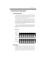
The print history shown below lists the printing dates of all Revisions and Addenda created
for this manual. The Revision Level letter increases alphabetically as the manual undergoes subsequent updates. Addenda, which are released between Revisions, contain important change information that the user should incorporate immediately into the manual. Addenda are numbered
sequentially. When a new Revision is created, all Addenda associated with the previous Revision
of the manual are incorporated into the new Revision of the manual. Each new Revision includes
a revised copy of this print history page.
Revision A (Document Number 2303-900-01) ............................................................ January 1998
Revision B (Document Number 2303-900-01) .......................................................... February 1998
Revision C (Document Number 2303-900-01) ............................................................. August 1998
Revision D (Document Number 2303-900-01) ........................................................November 1999
Addendum D (Document Number 2303-900-02) ........................................................October 2000
Revision E (Document Number 2303-900-01) ............................................................October 2000
Revision F (Document Number 2303-900-01).............................................................. August 2003
All Keithley product names are trademarks or registered trademarks of Keithley Instruments, Inc.
Other brand names are trademarks or registered trademarks of their respective holders.
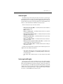
Safety Precautions
The following safety precautions should be observed before using this product and any associated instrumentation. Although
some instruments and accessories would normally be used with non-hazardous voltages, there are situations where hazardous
conditions may be present.
This product is intended for use by qualified personnel who recognize shock hazards and are familiar with the safety precautions
required to avoid possible injury. Read and follow all installation, operation, and maintenance information carefully before using the product. Refer to the manual for complete product specifications.
If the product is used in a manner not specified, the protection provided by the product may be impaired.
The types of product users are:
Responsible body is the individual or group responsible for the use and maintenance of equipment, for ensuring that the equipment is operated within its specifications and operating limits, and for ensuring that operators are adequately trained.
Operators use the product for its intended function. They must be trained in electrical safety procedures and proper use of the
instrument. They must be protected from electric shock and contact with hazardous live circuits.
Maintenance personnel perform routine procedures on the product to keep it operating properly, for example, setting the line
voltage or replacing consumable materials. Maintenance procedures are described in the manual. The procedures explicitly state
if the operator may perform them. Otherwise, they should be performed only by service personnel.
Service personnel are trained to work on live circuits, and perform safe installations and repairs of products. Only properly
trained service personnel may perform installation and service procedures.
Keithley products are designed for use with electrical signals that are rated Measurement Category I and Measurement Category
II, as described in the International Electrotechnical Commission (IEC) Standard IEC 60664. Most measurement, control, and
data I/O signals are Measurement Category I and must not be directly connected to mains voltage or to voltage sources with
high transient over-voltages. Measurement Category II connections require protection for high transient over-voltages often associated with local AC mains connections. Assume all measurement, control, and data I/O connections are for connection to
Category I sources unless otherwise marked or described in the Manual.
Exercise extreme caution when a shock hazard is present. Lethal voltage may be present on cable connector jacks or test fixtures.
The American National Standards Institute (ANSI) states that a shock hazard exists when voltage levels greater than 30V RMS,
42.4V peak, or 60VDC are present. A good safety practice is to expect that hazardous voltage is present in any unknown
circuit before measuring.
Operators of this product must be protected from electric shock at all times. The responsible body must ensure that operators
are prevented access and/or insulated from every connection point. In some cases, connections must be exposed to potential
human contact. Product operators in these circumstances must be trained to protect themselves from the risk of electric shock.
If the circuit is capable of operating at or above 1000 volts, no conductive part of the circuit may be exposed.
Do not connect switching cards directly to unlimited power circuits. They are intended to be used with impedance limited sources. NEVER connect switching cards directly to AC mains. When connecting sources to switching cards, install protective devices to limit fault current and voltage to the card.
Before operating an instrument, make sure the line cord is connected to a properly grounded power receptacle. Inspect the connecting cables, test leads, and jumpers for possible wear, cracks, or breaks before each use.
When installing equipment where access to the main power cord is restricted, such as rack mounting, a separate main input power disconnect device must be provided, in close proximity to the equipment and within easy reach of the operator.
For maximum safety, do not touch the product, test cables, or any other instruments while power is applied to the circuit under
test. ALWAYS remove power from the entire test system and discharge any capacitors before: connecting or disconnecting ca5/03
bles or jumpers, installing or removing switching cards, or making internal changes, such as installing or removing jumpers.
Do not touch any object that could provide a current path to the common side of the circuit under test or power line (earth) ground. Always make measurements with dry hands while standing on a dry, insulated surface capable of withstanding the voltage being measured.
The instrument and accessories must be used in accordance with its specifications and operating instructions or the safety of the
equipment may be impaired.
Do not exceed the maximum signal levels of the instruments and accessories, as defined in the specifications and operating information, and as shown on the instrument or test fixture panels, or switching card.
When fuses are used in a product, replace with same type and rating for continued protection against fire hazard.
Chassis connections must only be used as shield connections for measuring circuits, NOT as safety earth ground connections.
If you are using a test fixture, keep the lid closed while power is applied to the device under test. Safe operation requires the use
of a lid interlock.
If a
The
screw is present, connect it to safety earth ground using the wire recommended in the user documentation.
!
symbol on an instrument indicates that the user should refer to the operating instructions located in the manual.
The
symbol on an instrument shows that it can source or measure 1000 volts or more, including the combined effect of
normal and common mode voltages. Use standard safety precautions to avoid personal contact with these voltages.
The
symbol indicates a connection terminal to the equipment frame.
The WARNING heading in a manual explains dangers that might result in personal injury or death. Always read the associated
information very carefully before performing the indicated procedure.
The CAUTION heading in a manual explains hazards that could damage the instrument. Such damage may invalidate the warranty.
Instrumentation and accessories shall not be connected to humans.
Before performing any maintenance, disconnect the line cord and all test cables.
To maintain protection from electric shock and fire, replacement components in mains circuits, including the power transformer,
test leads, and input jacks, must be purchased from Keithley Instruments. Standard fuses, with applicable national safety approvals, may be used if the rating and type are the same. Other components that are not safety related may be purchased from
other suppliers as long as they are equivalent to the original component. (Note that selected parts should be purchased only
through Keithley Instruments to maintain accuracy and functionality of the product.) If you are unsure about the applicability
of a replacement component, call a Keithley Instruments office for information.
To clean an instrument, use a damp cloth or mild, water based cleaner. Clean the exterior of the instrument only. Do not apply
cleaner directly to the instrument or allow liquids to enter or spill on the instrument. Products that consist of a circuit board with
no case or chassis (e.g., data acquisition board for installation into a computer) should never require cleaning if handled according to instructions. If the board becomes contaminated and operation is affected, the board should be returned to the factory for
proper cleaning/servicing.
Table of Contents
1 Getting Started
General information .......................................................................... 1-2
Warranty information....................................................................... 1-2
Contact information ....................................................................... 1-2
Safety symbols and terms .............................................................. 1-2
Specifications ................................................................................. 1-2
Inspection ....................................................................................... 1-3
Options and accessories ................................................................. 1-3
Power supply overview ..................................................................... 1-4
Remote display option ....................................................................... 1-6
Power-up ............................................................................................ 1-6
Line power connection .................................................................. 1-6
Fuse replacement ........................................................................... 1-7
Power-up sequence ........................................................................ 1-7
Display modes ................................................................................... 1-8
Default settings .................................................................................. 1-9
Setups — Save, Power-on, and Recall ......................................... 1-10
Menu ................................................................................................ 1-11
Rules to navigate MENU ............................................................. 1-13
SCPI programming .......................................................................... 1-13
2 Basic Power Supply Operation
Test connections ................................................................................ 2-2
Outputting voltage and current .......................................................... 2-3
Setting output voltage and current limit ........................................ 2-3
Operate ........................................................................................... 2-8
SCPI programming — outputting voltage and current .................. 2-8
Reading back V and I ...................................................................... 2-11
Actual V and I display mode ........................................................ 2-11
Measurement configuration .......................................................... 2-11
SCPI programming — measure V and I, and DVM input ........... 2-12
Independent voltage measurements (DVM) .................................... 2-13
DVM input display mode ............................................................. 2-13
Measurement configuration .......................................................... 2-13
SCPI programming — DVM........................................................ 2-13
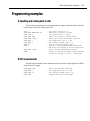
Sink operation ................................................................................. 2-14
Programming examples.................................................................... 2-15
Outputting and reading back V and I............................................ 2-15
DVM measurements ..................................................................... 2-15
3 Pulse Current Measurements
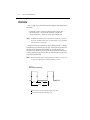
Overview ............................................................................................ 3-2
Trigger level ................................................................................... 3-3
Trigger delay .................................................................................. 3-3
Integration times ............................................................................ 3-3
Average readings count ..................................................................... 3-3
Measurement configuration ............................................................... 3-4
Current range .................................................................................. 3-4
Integration times ............................................................................ 3-4
Average readings count .................................................................. 3-5
Trigger delay and trigger level ........................................................ 3-5
Pulse current display mode ............................................................. 3-5
Pulse current measurement procedure ............................................ 3-6
Determining correct trigger level (pulse current) ........................... 3-6
SCPI programming ............................................................................. 3-7
Pulse current digitization ................................................................ 3-9
Programming examples ................................................................ 3-10
4 Long Integration Measurements
Overview ............................................................................................ 4-2
Integration time .............................................................................. 4-3
Trigger edge .................................................................................... 4-3
Trigger level ................................................................................... 4-3
Pulse timeout .................................................................................. 4-4
Measurement configuration ............................................................... 4-5
Current range .................................................................................. 4-5
Integration time ............................................................................... 4-5
Pulse timeout .................................................................................. 4-6
Trigger edge and trigger level ........................................................ 4-6
Long integration display mode ....................................................... 4-7
Long integration measurement procedure ........................................ 4-7
General notes .................................................................................. 4-8
Determining correct trigger level (long integration) ....................... 4-8
SCPI programming ............................................................................ 4-9
Programming example .................................................................. 4-11
5 Relay Control
Overview ...........................................................................................
Connections .......................................................................................
Controlling the relay ..........................................................................
SCPI programming ........................................................................
5-2
5-4
5-5
5-5
6 GPIB Operation
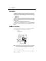
Introduction ....................................................................................... 6-2
GPIB bus connections ....................................................................... 6-2
Primary address ................................................................................. 6-3
Output format .................................................................................... 6-3
General bus commands ..................................................................... 6-4
REN (remote enable) ..................................................................... 6-4
IFC (interface clear) ....................................................................... 6-4
LLO (local lockout) ....................................................................... 6-5
GTL (go to local) ........................................................................... 6-5
DCL (device clear) ........................................................................ 6-5
SDC (selective device clear) .......................................................... 6-5
GET (group executive trigger) ....................................................... 6-5
SPE, SPD (serial polling) .............................................................. 6-5
Front panel aspects of GPIB operation ............................................. 6-6
Remote indicator and LOCAL key ................................................ 6-6
Error and status messages .............................................................. 6-6
Programming syntax ......................................................................... 6-7
Command words ............................................................................ 6-7
Program messages ....................................................................... 6-10
Response messages ...................................................................... 6-12
Message exchange protocol ......................................................... 6-12
7 Status Structure
Overview ...........................................................................................
Status byte and SRQ ......................................................................
Status register sets ..........................................................................
Queues ...........................................................................................
Clearing registers and queues ............................................................
Programming and reading registers ...................................................
Programming enable registers .......................................................
Reading registers ...........................................................................
Status byte and service request (SRQ) ..............................................
Status byte register .........................................................................
Service request enable register ......................................................
Serial polling and SRQ ..................................................................
Status byte and service request commands ....................................
7-2
7-2
7-2
7-2
7-4
7-5
7-5
7-5
7-6
7-7
7-7
7-8
7-9
Status register sets ............................................................................ 7-10
Register bit descriptions ............................................................... 7-10
Condition registers ....................................................................... 7-15
Event registers .............................................................................. 7-15
Event enable registers .................................................................. 7-16
Programming example — program and read
measurement event register .................................................... 7-17
Queues ............................................................................................. 7-17
Output queue ................................................................................ 7-17
Error queue ................................................................................... 7-18
8 Common Commands
Overview ............................................................................................ 8-2
*IDN? — identification query ........................................................ 8-3
*OPC — operation complete ......................................................... 8-3
*OPC? — operation complete query ............................................. 8-3
*SAV <NRf> — save ..................................................................... 8-4
*RCL <NRf> — recall ................................................................... 8-4
*RST — reset ................................................................................. 8-4
*TRG — trigger ............................................................................. 8-4
*TST? — self-test query ................................................................ 8-5
*WAI — wait-to-continue .............................................................. 8-5
9 Signal Oriented Measurement Commands
Overview ............................................................................................ 9-2
:FETCh? ......................................................................................... 9-2
:FETCh:ARRay? ............................................................................ 9-2
:READ? .......................................................................................... 9-3
:READ:ARRay? ............................................................................. 9-3
:MEASure[:<function>]? ............................................................... 9-4
:MEASure:ARRay[:<function>]? .................................................. 9-4
10 DISPlay, FORMat, and SYSTem
DISPlay subsystem ..........................................................................
:DISPlay:ENABle <b> ................................................................
:DISPlay:TEXT:DATA <a> .........................................................
:DISPlay:TEXT:STATe <b> ........................................................
FORMat subsystem .........................................................................
FORMat[:DATA] <type> .............................................................
FORMat:BORDer <name> ..........................................................
:SYSTem subsystem ........................................................................
:SYSTem:POSetup <name> ........................................................
10-2
10-2
10-2
10-3
10-4
10-4
10-6
10-7
10-7
11 SCPI Tables
SCPI command subsystems reference tables .................................. 11-2
A Specifications
B Error and Status Messages
C Emulation Commands
HP 6632A power supply emulation commands ............................... C-2
Fluke PM2811 power supply emulation commands ........................ C-5
D Emulation Commands
Selecting the 488.1 protocol.............................................................. D-2
Protocol differences............................................................................ D-3
List of Illustrations
1 Getting Started
High speed power supply .................................................................. 1-4
Simplified power supply diagram ...................................................... 1-5
2 Basic Power Supply Operation
Typical connections ........................................................................... 2-2
Output capabilities ............................................................................. 2-3
Sink operation example .................................................................... 2-12
3 Pulse Current Measurements
Pulse current measurement ................................................................ 3-2
5 Relay Control
Relay control ..................................................................................... 5-3
Miniature phono plug ........................................................................ 5-4
6 GPIB Operation
IEEE-488 connector .......................................................................... 6-2
7 Status Structure
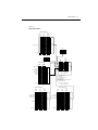
Status model structure ....................................................................... 7-3
16-bit status register .......................................................................... 7-5
Status byte and service request .......................................................... 7-6
Standard event status ....................................................................... 7-11
Operation event status ..................................................................... 7-12
Measurement event status ................................................................ 7-13
Questionable event status ................................................................ 7-14
10 DISPlay, FORMat, and SYSTem
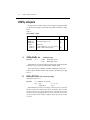
IEEE-754 single precision data format ........................................... 10-5
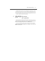
IEEE-754 double precision data format .......................................... 10-6
List of Tables
1 Getting Started
Factory defaults (RST) ...................................................................... 1-9
MENU structure .............................................................................. 1-12
2 Basic Power Supply Operation
Current ranges.................................................................................... 2-4
SCPI commands — outputting voltage and current ........................ 2-7
SCPI commands — measure V and I, and DVM input ................... 2-10
Sink current limits ............................................................................ 2-12
3 Pulse Current Measurements
SCPI commands — pulse current measurements ............................. 3-7
4 Long Integration Measurements
SCPI commands — long integration measurements ........................ 4-9
5 Relay Control
Switchcraft connection accessories ................................................... 5-4
SCPI command — output relay control ............................................ 5-5
6 GPIB Operation
General bus commands ..................................................................... 6-4
7 Status Structure
Common and SCPI commands — reset registers and clear queues .. 7-4
Command commands — status byte and service request
enable registers .................................................................... 7-9
Common and SCPI commands — condition registers ................... 7-15
Common and SCPI commands — event registers .......................... 7-15
Common and SCPI commands — event enable registers ............... 7-16
SCPI commands — error queue ..................................................... 7-19
8 Common Commands
IEEE-488.2 common commands and queries.................................... 8-2
*OPC and *OPC? commands ........................................................... 8-4
9 Signal Oriented Measurement Commands
Signal oriented measurement command summary ........................... 9-2
10 DISPlay, FORMat, and SYSTem
SCPI commands — display ............................................................. 10-2
SCPI commands — data format....................................................... 10-4
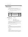
SCPI commands — system ............................................................. 10-7
11 SCPI Tables
DISPlay command summary ........................................................... 11-3
FORMat command summary .......................................................... 11-3
OUTPut command summary ........................................................... 11-3
SENSe command summary ............................................................. 11-4
SOURce command summary .......................................................... 11-6
STATus command summary ............................................................ 11-7
SYSTem command summary .......................................................... 11-8
C Emulation Commands
HP commands used to control the power supply .............................. C-2
Fluke commands used to control Model 2303/2303B/2303-PJ ....... C-5
1
Getting Started
•
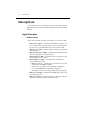
General information — Covers general information that includes warranty information, contact information, safety symbols and terms, inspection and available options and
accessories.
•
Power supply overview — Summarizes the capabilities of the power supply.
•
Remote display option — Explains how to use the optional Model 2304-DISP Display
Module.
•
Power-up — Covers line power connection, fuse replacement, and the power up
sequence.
•
Display modes — Explains the four display modes of the power supply.
•
Default settings — Lists the factory default settings, and explains how to save and recall
settings.
•
Menu — Provides a table that summarizes the menu items and includes rules to navigate
the menu structure.
•
SCPI programming — Explains how SCPI commands are presented in this manual.
1-2
Getting Started
General information
Warranty information
Warranty information is located at the front of this manual. Should your power supply require
warranty service, contact the Keithley representative or authorized repair facility in your area for
further information. When returning the instrument for repair, be sure to fill out and include the
service form at the back of this manual to provide the repair facility with the necessary information.
Contact information
If you have any questions after reviewing this information, please contact your local Keithley
representative or call one of our Applications Engineers at 1-800-3735 (U.S. and Canada only).
Worldwide phone numbers are listed at the front of this manual.
Safety symbols and terms
Keithley uses a standard set of safety symbols and terms that may be found on an instrument
or in its manual.
If a
screw is present, connect it to safety earth ground using the wire recommended in
the user documentation.
The ! symbol on an instrument indicates that the user should refer to the operating
instructions located in the manual.
The
symbol on an instrument shows that it can source or measure 1000 volts or more,
including the combined effect of normal and common mode voltages. Use standard safety precautions to avoid personal contact with these voltages.
The
symbol indicates a connection terminal to the equipment frame.
The WARNING heading used in a manual explains dangers that might result in personal
injury or death. Always read the associated information very carefully before performing the
indicated procedure.
The CAUTION heading used in a manual explains hazards that could damage the instrument. Such damage may invalidate the warranty.
Specifications
Full power supply specifications can be found in Appendix A of this manual.
Getting Started
1-3
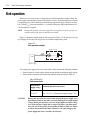
Inspection
The power supply was carefully inspected electrically and mechanically before shipment.
After unpacking all items from the shipping carton, check for any obvious signs of physical
damage that may have occurred during transit. (Note: There may be a protective film over the
display lens, which can be removed.) Report any damage to the shipping agent immediately.
Save the original packing carton for possible future shipment. The following items are included
with every order:
•
•
•
•
•
•
Model 2303/2303B/2303-PJ High Speed Power Supply with line cord
Quick Disconnect Output/DVM Input Connector
Accessories as ordered
Certificate of calibration
Model 2303/2303B/2303-PJ User’s Manual (P/N 2303-900-00)
Model 2303/2303B/2303-PJ Service Manual (P/N 2303-902-00)
If an additional manual is required, order the appropriate manual package. The manual package includes a manual and any pertinent addenda.
Any improvements or changes concerning the instrument or manual will be explained in an
addendum included with the manual. Be sure to note these changes and incorporate them into
the manual.
Options and accessories
The following options and accessories are available for the power supply.
•
•
•
•
•
•
•
2304-DISP remote display unit
Shielded IEEE-488 cable, 1m (3.3 ft) (P/N 7007-1)
Shielded IEEE-488 cable, 2m (6.6 ft) (P/N 7007-2)
Single fixed rack mount kit (P/N 4288-1)
Dual fixed rack mount kit (P/N 4288-2)
IEEE-488 Interface/controller for the PCI bus (P/N KPCI-488)
IEEE-488 interface card for IBM PC/AT (full slot) (P/N KPC-488-2AT)
1-4
Getting Started
Power supply overview
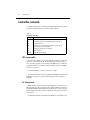
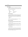
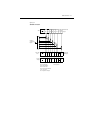
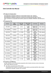
The power supply (shown in Figure 1-1) can output up to +15V at up to 3A or +9V at up to
5A. Voltage can be set in 1mV steps, and current limit can be set in 100µA steps. Maximum
power output is 45W. The power supply can also be used to sink current (up to 2A). As a sink
(current polarity is negative), the power supply is dissipating power rather than sourcing it (see
“Sink operation” for details).
NOTE
Model 2303B has a blank front panel except for a POWER switch and an ON/OFF
LED. All references to front panel messages, menus, and keystrokes apply to the
Models 2303 and 2303-PJ, and the 2303B if using the Model 2304-DISP remote
display module.
Figure 1-1
High speed power supply (Model 2303 shown)
LOCAL
2303 HIGH SPEED POWER SUPPLY 15V/3A 9V/5A
MENU
OPERATE
ENTER
SET
DISPLAY
POWER
A) Front Panel
WARNING:NO INTERNAL OPERATOR SERVICABLE PARTS,SERVICE BY QUALIFIED PERSONNEL ONLY.
LINE FUSE
SLOWBLOW
ISOLATION FROM EARTH:
22 VOLTS MAX.
2.0A, 250V
LINE RATING
+
+
SOURCE
+ _
SENSE
_
_
SOURCE
_
DVM
+
IN
100-120VAC/
200-240VAC
50, 60 HZ
150VA MAX
OUTPUT
15V/3A 9V/5A
IEEE-488
(CHANGE IEEE ADDRESS
WITH FRONT PANEL MENU)
MADE IN
U.S.A.
CAUTION:FOR CONTINUED PROTECTION AGAINST FIRE HAZARD,REPLACE FUSE WITH SAME TYPE AND RATING.
B) Rear Panel
RELAY
CONTROL
15VDC MAX
REMOTE
DISPLAY
OPTION
Getting Started
1-5
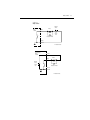
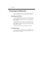
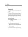
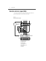
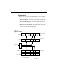
A simplified diagram of the power supply is shown in Figure 1-2. Note that it can read back
the output voltage (Vmeter) and current (Imeter). Display resolution for voltage readback is 1mV.
Current Readback Ranges:
•
Models 2303 and 2303B – Two ranges for current readback: 5A and 5mA. On the 5A
range, display resolution is 100µA, and on the 5mA range, resolution is 0.1µA.
•
Model 2303-PJ – Two ranges for current readback: 5A and 500mA. On the 5A range,
display resolution is 100µA, and on the 500mA range, resolution is 0.01mA (10µA).
The power supply also has a digital voltmeter (DVM) that is independent of the power supply
circuit. The DVM can measure up to +20V (1mV resolution).
When used with a pulsed load, the power supply can read back peak current, idle current, and
average current. See Section 3 for details. A long integration (up to 60 seconds) function is provided to measure average current of a low frequency pulse (long period) or a series of pulses.
See Section 4 for details.
Figure 1-2
Simplified power supply diagram
+
I meter
Source
V-Source
with I-Limit
V meter
_
+
DVM
Digital
Voltmeter
_
1-6
Getting Started
Remote display option
If the power supply must be mounted in a location where the display is not readily visible or
the controls are not easily accessible, the optional Model 2304-DISP Display Module can be
used. This display module includes all instrument controls and has a 9 foot cable so the power
supply can be operated remotely from a more convenient location.
NOTE
When the remote display is attached to a Model 2303B, the power supply acts like a
Model 2303.
The remote display module plugs into the rear panel connector labeled “REMOTE DISPLAY
OPTION” (see Figure 1-1B). When plugged in, the main display module is disabled with the
following message displayed:
REMOTE PANEL
ENABLED
When the remote display module is unplugged, control returns to the main display module.
NOTE
When connecting or disconnecting the 2304-DISP remote display, allow a few seconds for the power supply to recognize the action. Fast, repeated connects/disconnects of the remote display may cause the power supply to hang or appear to hang.
Disconnecting the remote display and waiting a few seconds to reconnect it may clear
the problem. If not, cycling power on the power supply clears the condition.
Power-up
Line power connection
The power supply operates from a line voltage in the range of 100 to 240V at a frequency of 50
or 60Hz. Line voltage and frequency are automatically sensed, therefore there are no switches to
set. Check to see that the line power in your area is compatible. Use the :SYSTem :LFRequency?
query (Section 10) to read the line frequency.
Perform the following steps to connect the power supply to the line power and turn it on:
1.
Before plugging in the power cord, make sure the front panel power switch is in the off (0)
position.
2.
Connect the female end of the supplied power cord to the AC receptacle on the rear panel.
Getting Started
WARNING
3.
1-7
The power cord supplied with the power supply contains a separate ground
for use with grounded outlets. When proper connections are made, instrument chassis is connected to power line ground through the ground wire in
the power cord. Failure to use a grounded outlet may result in personal injury or death due to electric shock.
Turn on the power supply by pressing the front panel power switch to the on (1) position.
Fuse replacement
A rear panel fuse protects the power line input of the power supply. If the line fuse needs to
be replaced, perform the following steps:
1.
The fuse is located in a drawer below the AC receptacle (see Figure 1-1B). At the top of the
fuse drawer is a small tab. At this location, use a thin-bladed knife or screwdriver to pry the
fuse drawer open.
2.
Slide the fuse drawer out to gain access to the fuse. Note that the fuse drawer does not pull
all the way out of the power module.
3.
Snap the fuse out of the drawer and replace it with the same type (250V, 2.0A, 5 × 20mm
time lag). The Keithley part number is FU-81.
CAUTION
4.
For continued protection against fire or instrument damage, only replace
the fuse with the type and rating listed. If the instrument repeatedly blows
fuses, locate and correct the cause of the problem before replacing the fuse.
Push the fuse drawer back into the power module.
Power-up sequence
On power-up, the power supply performs self-tests on its EPROM and RAM.
NOTE
If a problem develops while the instrument is under warranty, return it to Keithley
Instruments Inc., for repair.
If the instrument passes the self-tests, the following information is briefly displayed:
•
Top line — The model number and the IEEE-488 address are displayed. At the
factory, the address is set to 16.
•
Bottom line — Firmware revision levels are displayed for the main board and the display board. Also displayed is the detected line frequency.
After the power-up sequence, the instrument goes to the presently saved display type with the
output off (see “Default settings”).
1-8
Getting Started
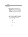
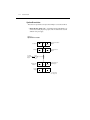
Display modes
For voltage and current readings, there are four display modes described as follows:
•
•
•
•
ACTUAL V AND I — This display mode is used to read back the actual output voltage
and current. This display mode is the RST default. (See Section 2 for details.)
DVM INPUT — This mode is used to display the DC voltage applied to the DVM input
of the power supply. (See Section 2 for details.)
PULSE CURRENT — This mode is used to display high, low, or average pulse-current
measurements. (See Section 3 for details.)
LONG INTEGRATION — This mode is used to display average current measurements of a pulse or pulses using the long integration method. (See Section 4 for details.)
A display mode is selected as follows:
1.
2.
Press the DISPLAY key and use the or key to display the desired mode: ACTUAL
V AND I, DVM INPUT, PULSE CURRENT, or LONG INTEGRATION.
With the desired mode displayed, press ENTER. Note that after selecting PULSE CURRENT, use the or key to select the desired pulse measurement: pulse high, pulse low,
or pulse average. Examples of the display modes are shown as follows:
Actual V and I:
6.116 V
1.2058 A
ON
DVM input:
DVM INPUT
4.993 V
ON
Pulse current:
PULSE HI
2.1947 A
ON
PULSE LO
0.2147 A
ON
PULSE AVG
1.1495 A
ON
Long integration: LONG INT
1.0236 A
ON
Getting Started
1-9
NOTES “ON” indicates that the output is turned on. With the output turned off, “OFF” is displayed. See Section 10 for details.
For the Pulse Current and Long Integration display modes, “NO PULSE” is
displayed if the output is off or pulses are not detected (output on). See Sections 3 and
4 for details.
When a change is made that affects the readings being taken, dashes are displayed
instead of readings. The dashes remain until a valid reading for the new condition is
taken.
Any one of the four display modes can be the power-on default. Use the SAVE SETUP
item of the MENU to save the selected display mode in memory, and use the POWER
ON SETUP item to specify the power-on setup (see “Setups” under “Default settings” for details).
Default settings
The power supply can be set to power-on to the factory default conditions (RST defaults) or
to user-saved setup conditions. The factory default conditions are listed in Table 1-1.
Table 1-1
Factory defaults (RST)
Setting
Output value settings:
Voltage (V)
Current (A)
Output state operate
Display type
GPIB address
GPIB output format
Current range
Integration rate
Average readings
Power on setup
Current limit mode
Output relay
Pulse current:
High time
Low time
RST default
0.000V
0.2500A
Off
Actual V and I
No effect (factory set to 16)
No effect (factory set to Keithley
and Exponential)
5 amps (Auto Range off)
1.00 PLC
1
No effect (factory set to RST)
Lim
No effect (after power cycle, set
to zero)
33 µsec
33 µsec
1-10
Getting Started
Table 1-1 (cont.)
Factory defaults (RST)
Setting
Average time
Average readings
Trigger delay
Trigger level:
Models 2303 and 2303B
Model 2303-PJ:
5A range
500mA range
Long integration:
Integration time
Pulse timeout
Trigger edge
Trigger level:
Models 2303 and 2303B
Model 2303-PJ:
5A range
500mA range
RST default
33 µsec
1
0.00000 sec
0.000A
0.000A
0.0000A
1 second
16 seconds
Rising
0.000A
0.000A
0.0000A
Setups — Save, Power-on, and Recall
Setups are configured by SAVE SETUP, POWER ON SETUP and RECALL SETUP items
of the MENU (which is accessed by pressing the MENU key).
NOTE
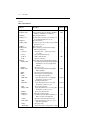
Table 1-2 shows the menu structure. Rules to navigate the menu follow the table.
The setup MENU items are explained as follows:
•
•
•
SAVE SETUP - Save the present power supply setup to a memory location;
SAV0-SAV4.
RECALL SETUP - Return the power supply to the RST defaults (Table 1-1), or to one
of the user saved setups; SAV0-SAV4. Note the operate state (output) is always recalled
as OFF.
POWER-ON SETUP - Select the setup to use at power-up; RST, SAV0-SAV4 (output
off) or SAV5-SAV9 (output on or off). Note that SAV5-SAV9 are not available for the
Model 2303-PJ.
When powering up to the SAV0, SAV1, SAV2, SAV3, or SAV4 setup, the output will be off
regardless of the operate state when the setup was saved. For example, if the output is on when
the setup is saved as SAV0, the power supply will power up with the output off for the SAV0
power-on setup.
Getting Started
1-11
If you want the Model 2303 or 2303B to power up with the output on, you must use SAV5,
SAV6, SAV7, SAV8, or SAV9 as the power-on setup. For the SAV5 power-on setup, the power
supply will power up to the SAV0 settings, and the output will be on or off depending on the
output state when the setup was saved as SAV0. For example, assume the output is on and the
setup is saved as SAV0. With SAV0 as the power-on setup, the power supply will power up with
the output off. With SAV5 as the power-on setup, the power supply will power up with the output
on.
Power-On Setups:
NOTE
SAV5 through SAV9 are not available for the Model 2303-PJ.
Models 2303, 2303B and 2303PJ:
SAV0 (output off)
SAV1 (output off)
SAV2 (output off)
SAV3 (output off)
SAV4 (output off)
Models 2303 and 2303B:
SAV5 (SAV0 setup with output on or off)
SAV6 (SAV1 setup with output on or off)
SAV7 (SAV2 setup with output on or off)
SAV8 (SAV3 setup with output on or off)
SAV9 (SAV4 setup with output on or off)
NOTE
For GPIB operation, the setups are saved and recalled using the *SAV, *RCL, and
*RST commands. (See Section 8 for details.) The power-on setup is selected using the
SYSTem:POSetup command (Section 10).
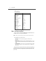
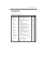
Menu
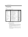
Many aspects of operation are configured from the menu that is summarized in Table 1-2. Use
the following rules to navigate through the menu structure.
NOTE
The menu key is used to access the menu structure. However, if in remote for IEEE488 bus operation (“R” displayed below “ON/OFF”) the menu key returns the instrument to LOCAL operation.
1-12
Getting Started
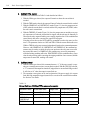
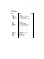
Table 1-2
MENU structure
Menu item
GPIB menu
Address
Output format
Exponential
2 decimal places
3 decimal places
4 decimal places
Keithley
Fluke
Current range
Integration rate
Average readings
Save setup
Recall setup
Power on setup
Calibrate unit
Current lim mode
Output relay
Revision number
Serial number
Pulse current
High time
Low time
Average time
Auto time
Average readings
Trigger delay
Trigger level
Long integration
Integration time
Auto time
Pulse timeout
Trigger edge
Trigger level
Description
GPIB configuration:
Set primary address (0 to 30).
Select format for GPIB readings:
Return readings in exponent form (i.e. +1.00000000+01).
Return readings using 2 decimal places (i.e. 10.00).
Return readings using 3 decimal places (i.e. 10.000).
Return readings using 4 decimal places (i.e. 10.0000).
Reply with Keithley information to *IDN?
Reply with Fluke information to *IDN?
Select current range:
Models 2303 and 2303B – 5A, 5mA or AUTO.
Model 2303-PJ – 5A, 500mA or AUTO
Set integration rate in NPLC (0.01 to 10).
Set average reading count (1 to 10).
Save present setup in memory (SAV0–SAV4).
Recall setup from memory (RST, SAV0–SAV4).
Select power-on setup (RST, SAV0–SAV4).*
Calibrate Model 2303/2303B/2303-PJ (see Service Manual).
Select current limit mode (Limit, Trip, Limit Relay, or Trig Relay).
Close (ONE) or open (ZERO) relay control circuit.
Display firmware revision levels.
Display serial number of the power supply.
Pulse-current configuration:
Set high time integration rate (in µsec.).
Set low time integration rate (in µsec.).
Set average time integration rate (in µsec.).
Set pulse integration rates automatically.
Set average reading count (1 to 100).
Set trigger delay in seconds (0 to 100msec).
Set trigger level:
Models 2303 and 2303B – 0 to 5A.
Model 2303-PJ: 5A range – 0 to 5A
500mA range – 0 to 500mA.
Long integration configuration:
Manually set integration time (up to 60 sec).
Automatically set integration time.
Set the “NO PULSE” timeout period (1 to 63 sec).
Select trigger edge (rising, falling or neither).
Set trigger level:
Models 2303 and 2303B – 0 to 5A.
Model 2303-PJ: 5A range – 0 to 5A
500mA range – 0 to 500mA.
* Models 2303 and 2303B also have SAV5-SAV9.
Notes: 1. See “Default settings” in this section to save and recall setups.
2. Revision Number displays the firmware revision level for the microcontroller and the display.
3. Serial Number displays the serial number of the power supply.
Ref
Sec 6
Sec 2
Sec 2
Sec 2
Note 1
Note 1
Note 1
Sec 2
Sec 5
Note 2
Note 3
Sec 3
Sec 4
Getting Started
1-13
Rules to navigate MENU
•
•
•
•
•
•
The MENU is accessed by pressing the MENU key.
Use the and edit keys to display the primary menu items.
A displayed primary menu item is selected by pressing ENTER. With PULSE CURRENT or LONG INTEGRATION selected, use the and edit keys to display the secondary items and press ENTER to select the displayed item.
Settings and selections for a menu item are displayed using the edit keys (,, , and ):
— For a setting, use or to place the cursor on the appropriate digit, and use and to increment and decrement the value (unless noted otherwise).
— For a selection, use or to display the desired option (unless noted otherwise).
With the desired setting or selection displayed, press ENTER for it to take effect. Pressing MENU will cancel the edit operation.
Use the MENU key to back out of the MENU structure.
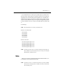
SCPI programming
SCPI programming information is integrated with front panel operation throughout this manual. SCPI commands are listed in tables, and additional information that pertains exclusively to
remote operation is provided after each table. Also, the SCPI tables may reference other sections
of this manual.
NOTE
Except for Section 11, all SCPI tables in this manual are abridged. That is, they exclude most optional command words and query commands. Optional command words
and query commands are summarized as follows.
Optional Command Words — In order to be in conformance with the IEEE-488.2 standard,
the power supply accepts optional command words. Any command word that is enclosed in
brackets ([]) is optional and does not have to be included in the program message.
Query commands — Most command words have a query form. A query command is identified by the question mark (?) that follows the command word. A query command requests (queries) the programmed status of that command. When a query is sent and the power supply is
addressed to talk, the response message is sent to the computer.
NOTE
For complete details, see “Programming syntax” in Section 6.
1-14
Getting Started
2
Basic Power Supply Operation
• Test connections — Explains how to connect the device under test (DUT) to the
power supply output, and how to connect an external voltage to the DVM input.
• Outputting voltage and current — Explains how to output voltage and current.
• Reading back V and I — Covers the Actual V and I display mode, which is used to
measure and display the actual voltage and current being delivered to the DUT.
• Independent voltage measurements (DVM Input) — Explains how to use the
digital voltmeter (DVM) to make DC voltage measurements.
• Sink operation — Explains how to use the power supply to dissipate power, rather
than sourcing it.
• Programming examples — Provides two examples: one to output and read back
voltage and current, and one to measure the DVM input.
2-2
Basic Power Supply Operation
Test connections
WARNING
When installing a unit into a test system, make sure the external power
sources do not apply voltage to the power supply in excess of its maximum
limits (see specifications). Failure to do so could result in personal injury or
death.
Test connections to the power supply are made at the rear panel using a quick disconnect
OUTPUT/DVM IN connector (Keithley part number CS-846). Figure 1-1B shows where the
connector plugs in. Use up to #14 AWG wire for the screw terminals of the connector. Once the
connector is wired up, plug it into the rear panel and tighten the captive retaining screws.
Figure 2-1 shows typical power supply connections to the device under test.
NOTE
Source I/O terminals are rated up to 10A maximum per pin. Two sets of Source +
and Source - terminals are available. This configuration allows you to wire source
connections in parallel to reduce the effects of wire impedance or to have two separate loads. The two Source + pins and the two Source - pins are internally connected to respective terminals on the PC board.
Figure 2-1
Typical connections
Quick
Disconnect
Connector
(Part # CS-846)
External
Test
Circuitry
+
DVM
Input
DVM +
_
DVM Source Source -
Output
Sense Sense +
Source +
Source +
DUT
Basic Power Supply Operation
2-3
Outputting voltage and current
The fundamental process to output voltage and current is to 1) set the output voltage and current limit values, and 2) press the OPERATE key. The details of this process are discussed as
follows.
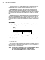
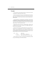
Setting output voltage and current limit
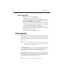
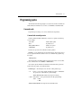
The output capabilities of the power supply are shown in Figure 2-2. Figure 2-2A shows the
output capabilities for the 5A and AUTO measurement ranges. Notice that when voltage is set
to more than 9V, the maximum current limit is 3A.
Figure 2-2
Output capabilities
I-Limit
5A
3A
V-Source
9V
15V
A) 5A or AUTO Measurement Range
I-Limit
1A
V-Source
B) 5mA Measurement Range (Models 2303 and 2303B)
15V
I-Limit
0.6A
V-Source
C) 500mA Measurement Range (Model 2303-PJ)
15V
2-4
Basic Power Supply Operation
The current limit setting for the 5 AMPS and AUTO ranges is “remembered” by that range.
For the following examples, assume the current limit setting on the 5 amps range is 3A.
Models 2303 and 2303B – Selecting the 5 MILLIAMPS range defaults the current limit
setting to 1A since that is the maximum allowable setting on that range. Toggling back to the
5 amps range reinstates the 3A limit. If the current limit value on the 5 amps range is ≤1A, the limit
on the 5 milliamps range will be the same when switching from the 5A range to the 5 milliamps
range.
Model 2303-PJ – Selecting the 500 milliamps range defaults the current limit setting to 0.6A
since that is the maximum allowable setting on that range. Toggling back to the 5 amps range
reinstates the 3A limit. If the current limit value on the 5 amps range is ≤0.6A, the limit on the
500 milliamps range will be the same when switching from the 5A range to the 500 milliamps
range.
Current ranges
The power supply current ranges are listed in Table 2-1. With auto range selected, the instrument will automatically go to the most sensitive range to perform the measurement.
Table 2-1
Current ranges
Power supply
Current ranges
Models 2303 and 2303B
Model 2303-PJ
5A, 5mA and AUTO
5A, 500mA and AUTO
Current range selection - The current measurement range is selected from the current range
item of the menu. The menu is accessed by pressing the MENU key.
NOTE
Table 1-2 (in Section 1) shows the menu structure. Rules to navigate the menu follow
the table.
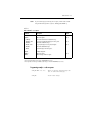
Current limit modes
If the current limit is reached, the output will either turn off (trip) or stay on (lim). The current
limit can also be used to control an external relay (Section 5). The four current limit modes are
summarized in Table 2-2 and explained below.
NOTE
The LIMIT RELAY and TRIP RELAY modes are available in the Models 2303 and
2303B with firmware revision A06 and later. Use the FIRMWARE
REVISION selection in the MAIN MENU to display the revision level.
Basic Power Supply Operation
2-5
Table 2-2
Front panel current limit selections
Submenu choice*
Current limit effect
Output state
External relay state
LIMIT
TRIP
LIMIT RELAY
TRIP RELAY
Current will be limited.
Current will trip.
Current will be limited.
Current will trip.
Remains on
Goes off
Remains on
Goes off
Not affected.
Not affected.
Tracks current limit state.
Tracks current limit state.
* LIMIT RELAY and TRIP RELAY available in Models 2303 and 2303B with firmware revision level A06
and higher.
LIM mode - With the lim mode selected, the output will remain on when the current limit
is reached. The “LIM” message will appear on the lower line of the display, after the current
reading indicator (A or mA). The message will clear when the limit condition is cleared.
The power supply can be taken out of the current limit by decreasing the output voltage or
increasing the current limit value. Note that increasing the current limit may compromise protection for the DUT.
While in the current limit, the power supply is operating as a constant-current source. As long
as the limit condition exists, the power supply output current will remain constant. Note that the
output voltage is probably less than the programmed value when sourcing current.
NOTE
The power supply does not provide LIM mode current limiting during sink operation.
TRIP mode - With the trip mode selected, the output will turn off when the current limit is
reached. The “TRIP” message will appear on the lower line of the display, after the current reading indicator (A or mA). The message will clear when the output is turned back on, assuming it
does not trip again due to a current limit condition.
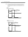
LIMIT RELAY mode - With the limit relay mode (Figure 2-3), the relay output turns on
(ONE) when the current limit is reached, and the relay output turns off (ZERO) when the unit is
not in current limit.
TRIP RELAY mode - With the trip relay mode (Figure 2-4), the relay output turns on and
the power supply output turns off when the current limit is tripped, and the unit must be manually reset to turn the relay output off and the power supply output back on. If the condition that
caused the trip has not be corrected, the output will trip again.
As discussed in Section 5, you can also use the OUTPUT RELAY submenu to set the relay
state to ONE (relay closed) and ZERO (relay open). With current limit mode set to LIMIT or
TRIP, the relay state operates independently based on the menu choice selected. However, with
LIMIT RELAY and TRIP RELAY, the menu choices may be used to override the relay state and
cause the relay state not to track the current limit state. For LIMIT RELAY, this condition may
exist only momentary while the limiting condition still exists. TRIP RELAY allows you to clear
the relay tracking while correcting the tripping condition. Once corrected and the output state is
turned on, tracking will resume.
2-6
Basic Power Supply Operation
NOTE
When the current limit relay control mode is selected, the relay may chatter or not
have sufficient time to pull in if the current value is fluctuating around the set current limit, depending on how rapidly the current is fluctuating around the current
limit point.
Figure 2-3
Relay control mode - limit relay
Limit Setting
Current
On
Relay
Off
Figure 2-4
Relay control mode - trip relay
Limit Setting
Current
Output turns off
due to Trip Mode
User turns output on, and
trip condition is corrected.
Otherwise, output will trip again.
On
Relay
Off
Basic Power Supply Operation
2-7
Current limit mode selection - The current limit mode is selected from the current lim
mode item of the menu. The menu is accessed by pressing the MENU key.
NOTE
Table 1-2 (in Section 1) shows the menu structure. Rules to navigate the menu follow
the table.
Procedure to edit voltage and current values
The following procedure assumes that the appropriate current range is already selected.
Editing keys — Once in the output settings mode, the four editing keys (ß, ©, ¹ and ƒ) are used
to set values. Cursor position (blinking digit) is controlled by the ß and © keys. With the cursor
positioned on a digit, increment or decrement the value using the ¹ and ƒ keys.
Perform the following steps to edit voltage and current values:
1.
Press the SET key to select the output settings mode. A blinking cursor appears in the
voltage field of the display.
2.
Use the ß, ©, ¹ and ƒ keys to key in the desired output voltage value and press SET. The
blinking cursor moves to the current field of the display.
3.
Use the ß, ©, ¹ and ƒ keys to key in the desired current limit and press SET to exit from
the output settings mode.
Editing shortcuts
With the output OFF, the following editing shortcuts can be used:
• Output voltage can be quickly set to the maximum value by incrementing the tens
digit (MSD). Note that if the tens digit is zero, it is not displayed. Place the cursor to
the left of the units digit.
• Output voltage can be quickly set to zero (0.000 V) by decrementing the first leading
zero of the reading. If there is no leading zero, decrement the tens digit.
• Current limit on the 5A range can be quickly set to its maximum value by
incrementing the units digit (MSD).
• Current limit on either range can be quickly set to the minimum value (0.0001 A) by
decrementing the first leading zero of the reading. If there is no leading zero,
decrement the units digit.
Editing restrictions
With the output ON, the following editing restrictions are in effect:
• You cannot increment a digit that would display a value that exceeds the maximum.
For example, for the value 14.200 V, you cannot increment the “1” or the “4” since the
resultant value would exceed 15.000 V.
• When decrementing a digit, only that digit and digits to the left are affected. The
digits to the right of the cursor are not changed.
2-8
Basic Power Supply Operation
NOTES The SET key is active in any front panel menu or display mode. If not already in the
output settings mode, the SET key will select it.
The V and I DACs are updated in real time. Therefore, if the output is on, the output
is updated immediately when a value is altered.
After pressing SET to exit the output settings mode, the instrument returns to the
previous display mode or front panel menu.
Operate
The OPERATE key is used to control the output of the power supply. This key toggles the
output between on and off. While in one of the display modes, output ON or OFF is displayed
in the upper right hand corner of the display. The key is active in any front panel menu or display
mode. In menus, the on/off state of operate is not displayed. Note that DVM measurements can
be performed with the output off.
SCPI programming — outputting voltage and current
The commands to output voltage and current are summarized in Table 2-3. The “Outputting
and reading back V and I” programming example at the end of this section demonstrates how to
use these commands.
Table 2-3
SCPI commands — outputting voltage and current
Commands
Description
Default
Ref
SENSe
:CURRent
:RANGe
[:UPPer] <n>
:AUTO <b>
SENSe subsystem:
Current function:
Set current measurement range:
Specify expected current in amps; 0 to 5.
Enable or disable auto range.
5.0
OFF
A
B
[SOURce]
:VOLTage <n>
:CURRent <n>
:TYPe <name>
SOURce subsystem:
Set voltage amplitude in volts; 0 to 15 (1mV resolution).
Set current limit value in amps; 0 to 5 (100µA resolution).
Select current limit type; LIMit, TRIP,
LIMRELAY (LIMITRELAY), or TRIPRELAY. *
Query state of current limit.
0.0
0.25
LIM
C
D
E
:STATe?
OUTPut
[:STATe] <b>
OUTPut subsystem:
Turn the power supply output on or off.
F
OFF
* LIMRELAY (LIMITRELAY) and TRIPRELAY available in Models 2303/2303B with firmware revision level A06 and higher.
Basic Power Supply Operation
2-9
A. SENSe:CURRent:RANGe <n>
1. After specifying a current value, the instrument will go to the most sensitive range to
accommodate that reading. For example, if you are going to set current limit to 750mA,
you can let <n> = 0.75 (or 750e-3) to select the 5A range. Another way to select a range
is to use the MINimum and MAXimum parameters as follows:
SENS:CURR:RANG MIN‘ Select the low current range (5mA or 500mA).
SENS:CURR:RANG MAX‘ Select the high current range (5A).
2. Using this command to manually select the current range disables auto range.
B. SENSe:CURRent:RANGe:AUTO <b>
This command is coupled to the :RANGe <n> command. When auto range is enabled,
the parameter value <n> for :RANGe changes to the automatically selected range value.
If you then disable auto range, the instrument will remain at the automatically selected
range.
C. VOLTage <n>
1. If the present current limit value is above 3A, setting the output voltage above 9V will
automatically default the current limit to 3A.
2. The response to VOLTage? is affected by the GPIB output format. For decimal formats,
the response has three decimal places, otherwise it is in exponential format (see Section
10 for details).
D. CURRent <n>
1. 5A or AUTO measurement range selected - With output voltage set to ≤9V, the maximum current limit value is 5A. With voltage set to >9V, the maximum current limit is
3A.
2. Models 2303 and 2303B:
• With the 5mA measurement range selected, the maximum current limit is 1A.
• Sending a value that exceeds 1A is rejected, and the following message is displayed
briefly:
CURRENT LIMIT ON
mA RANGE <= 1A
3. Model 2303-PJ:
• With the 500mA measurement range selected, the maximum current limit is 0.6A.
• Sending a value that exceeds 0.6A is rejected, and the following message is displayed
briefly:
CURRENT LIMIT ON
mA RANGE <= 0.6A
4. The response to CURRent? is affected by the GPIB output format. For decimal formats,
the response has four decimal places, otherwise it is in exponential format (see Section
10 for details).
2-10
Basic Power Supply Operation
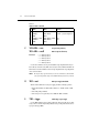
E.
CURRent:TYPe <name>
Parameters are summarized in Table 2-4 and described as follows:
1. With the LIMit type selected, the output will remain on when the current limit is
reached.
2. With the TRIP mode selected, the output will turn off when the current limit is reached.
3. With the LIMRELAY (or LIMITRELAY) mode (Figure 2-3), the relay output turns on
(ONE) when the current limit is reached, and the relay output turns off (ZERO) when
the unit is not in current limit.
4. With the TRIPRELAY mode (Figure 2-4), the relay output turns on and the power supply output turns off when the current limit is tripped, and the unit must be manually reset to turn the relay output off and the power supply output back on. If the condition that
caused the trip has not be corrected, the output will trip again.
Note that you can also use the OUTPut:RELay command to set the relay state (see Section 5). The parameter choices are ONE and ZERO. With the current limit mode set to
LIMit or TRIP, the relay state operates independently based on the command parameter.
However, with LIMRELAY (or LIMITRELAY) and TRIPRELAY, the command parameters may be used to override the relay state and cause the relay state not to track
the current limit state. For LIMRELAY, this condition may occur only momentary
while the limiting condition still exists. With TRIPRELAY, this condition allows you to
clear the relay tracking while correcting the tripping condition. Once corrected, and the
output state is turned ON, tracking will resume.
F.
CURRent:STATe?
1. With the LIMit type selected, this command returns a “1” if the power supply is operating as a constant-current source (current limit reached). With the TRIP type selected,
a “1” is returned if the output has turned off (tripped) due to current limit being reached.
It will clear to “0” when the output is turned back on.
2. The operation event register can be read to determine if the power supply is in current
limit and if the output has tripped (turned off) as a result of the current limit condition.
See Section 7 for details.
Table 2-4
Current limit type (CURRent:TYPe) command parameters
Parameter choice
Current limit effect
Output state
External relay state
LIMit
TRIP
LIMRELAY or
LIMITRELAY
TRIPRELAY
Current will be limited.
Current will trip.
Current will be limited.
Remains on
Goes off
Remains on
Not affected.
Not affected.
Tracks current limit state.
Current will trip.
Goes off
Tracks current limit state.
Basic Power Supply Operation
2-11
Reading back V and I
Actual V and I display mode
Measured output voltages and currents are displayed with the actual V and I display mode
selected. This display mode is selected as follows:
NOTE
If output settings are presently being displayed (as denoted by a blinking digit in the
voltage or current field), keep pressing the SET key until the blinking stops. The instrument can now display measured readings.
1. Press the DISPLAY key to access the display menu.
2. Press the ¹ or ƒ key until “ACTUAL V AND I” is displayed.
3. Press ENTER. Voltage readings are located on the top line of the display, and current
readings are located on the bottom line.
NOTE For details on display modes, see “Display modes” in Section 1.
Measurement configuration
CURRENT RANGE, INTEGRATION RATE and the AVERAGE READINGS count can be
checked or changed from the menu (which is accessed by pressing the MENU key).
NOTE
Table 1-2 (in Section 1) shows the menu structure. Rules to navigate the menu follow
the table.
Current range
Current range is linked with current limit. Therefore, as a general rule, the user selects the
current range before setting the current limit. The current range can be changed at any time, but
selecting the lower range may change the current limit setting. See “Outputting voltage and current” (in this section) for details on current range and current limit.
Integration rate
The integration (reading) rate of the instrument is specified as a parameter based on the number of power-line cycles (NPLC), where 1 PLC for 60Hz line frequency is 16.67msec (1/60). In
general, the fastest integration time (0.01 PLC) results in increased reading noise. The slowest
integration time (10 PLC) provides the best common-mode and normal-mode rejection.
In-between settings are a compromise between speed and noise.
The INTEGRATION RATE item of the menu is also used to set the reading rate for DVM
measurements. Note that it is not used to set the integration rate for pulse current and long integration measurements. These measurements are covered in Sections 3 and 4, respectively.
2-12
Basic Power Supply Operation
Average readings
The average reading count (1 to 10) specifies the number of measurement conversions to
average for each reading. For example, with a reading count of 5, each displayed reading will
be the average of five measurement conversions.
The AVERAGE READINGS item of the menu is also used to set the average reading count
for DVM measurements. Note that it is not used to set the average reading count for pulse current and long integration measurements. These measurements are covered in Sections 3 and 4,
respectively.
SCPI programming — measure V and I, and DVM input
The commands to measure output voltage and current, and the DVM input are summarized
in Table 2-5. The “Programming examples” at the end of this section demonstrates how to use
these commands.
Table 2-5
SCPI commands — measure V and I, and DVM input
Commands
Description
SENSe
:FUNCtion <name>
SENSe subystem:
Select readback function; “VOLTage”, “CURRent”,
or “DVMeter”.
Set integration rate (in line cycles) for voltage, current,
and DVM measurements; 0.01 to 10.
Specify the average count for voltage, current, and
DVM measurements; 1 to 10.
:NPLCycles <n>
:AVERage <NRf>
READ?
READ:ARRay?
Trigger and return one reading.
Trigger an array of readings and return them.
Default
Ref
A
VOLT
1.0
1
B
B
B
A. SENSe:FUNCtion <name>
1. The parameter name can instead be enclosed in single quotes (e.g., ‘CURRent’).
2. With “DVMeter” selected, the instrument measures the voltage applied to the input of
the digital voltmeter (DVM).
3. The “PCURrent” and “LINTegration” parameters for :FUNCtion (which are not listed
in Table 2-5) select the pulse current and long integration measurement modes. These
measurement modes are covered in Sections 3 and 4, respectively.
B. SENSe:AVERage <NRf>
1. When requesting a single reading (FETch?, READ?, or MEASure?), average count
specifies the number of measurement conversions to average for the reading. For example, with the average count set to 10, READ? will trigger 10 measurement conversions
and return (and display) the average of those 10 conversions.
Basic Power Supply Operation
2-13
2. When requesting an array of readings (FETCh:ARRay?, READ:ARRay? or
MEASure:ARRay?), average count specifies the number of measurements to place in
an array. For example, with the average count set to 10, READ:ARRay? will trigger and
return 10 readings.
3. Signal oriented measurement commands (e.g., READ?) are covered in Section 9.
Independent voltage measurements (DVM)
The power supply has an independent digital voltmeter (DVM) that can measure up to
+20VDC. Connections for the DVM are shown in Figure 2-1.
DVM input display mode
The DVM input display mode must be selected in order to measure voltage applied to DVM
input of the power supply. This display mode is selected as follows:
NOTE
If output settings are presently being displayed (as denoted by a blinking digit in the
voltage or current field), keep pressing the SET key until the blinking stops. The instrument can now display measured readings.
1. Press the DISPLAY key to access the display menu.
2. Press the ¹ or ƒ k ey until “DVM INPUT” is displayed.
3. Press ENTER.
NOTE
For details on display modes, see “Display modes” in Section 1.
Measurement configuration
The INTEGRATION RATE and AVERAGE READINGS count for DVM measurements can
be checked or changed from the menu (which is accessed by pressing the MENU key).
NOTE
Table 1-2 (in Section 1) shows the menu structure. Rules to navigate the menu follow
the table.
These two measurement configuration menu items are the same ones used for actual V and I
measurements. See “Reading back V and I, Measurement configuration” for details on integration rate and average reading count.
SCPI programming — DVM
The commands to perform actual V and I measurements are also used to perform DVM measurements. These commands are documented in Table 2-5.
The “DVM measurements” programming example at the end of this section demonstrates
how to use these commands to measure the DVM input.
2-14
Basic Power Supply Operation
Sink operation
Whenever a test circuit sources a voltage that exceeds the programmed supply voltage, the
power supply automatically becomes a sink instead of a source. It then dissipates power instead
of supplying power, while continuing to maintain the programmed supply voltage at its terminals. Current (Isink) flows into the positive (+) terminal of the power supply rather than out of it.
Current readback is negative.
NOTE
During sink operation, the power supply does not regulate current. It acts only as a
constant voltage load, not as a constant current load.
Figure 2-5 illustrates an application for sink operation. In Figure 2-5, the test circuit is a battery charging circuit; the power supply acts as a constant voltage battery load.
Figure 2-5
Sink operation example
Charger Circuit
R
+
I sink
3.0V
V
+
_
4.2V
_
Power Supply
To keep the power supply in the current sink mode, safely, maintain the following condition:
•
•
Ensure that the test circuit voltage remains greater than the programmed supply voltage.
Ensure that the maximum sink current falls within the limits specified in Table 2-6.
Table 2-6Table 2-6
Sink current limits
CAUTION
Programmed
supply voltage
Maximum allowable sink current
0V to 5V
2.0A
5V to 15V
2.0A - [0.1A/V) × (Programmed supply voltage - 5V)]
During sink operation, the current limit circuit of the power supply is not
operational, because it only limits current by limiting power supply output
voltage. During sink operation, your test circuit supplies net input voltage,
over which the power supply has no control. Therefore, you must ensure
that your test circuit sources current within the limits of Table 2-6. Failure
to source current within the limits of Table 2-6 can cause damage to the
power supply that is not covered by the warranty.
Basic Power Supply Operation
2-15
Programming examples
Outputting and reading back V and I
The following command sequence demonstrates how to output voltage and current, and read
back (measure) the actual voltage and current:
VOLT 5
SENS:CURR:RANG:AUTO ON
CURR 750e-3
CURR:TYPE TRIP
SENS:FUNC ‘VOLT’
SENS:NPLC 2
SENS:AVER 5
OUTP ON
READ?
SENS:FUNC ‘CURR’
READ?
‘
‘
‘
‘
‘
‘
‘
‘
‘
Set output voltage to 5V.
Enable auto range for current.
Set current limit to 750mA.
Select Trip mode for current limit.
Select the voltage measurement function.
Set integration rate to 2 PLC.
Set average reading count to 5.
Turn on the power supply output.
Trigger 5 voltage measurement conversions
and return the average of those 5 conversions.
‘ Select current measurement function.
‘ Trigger 5 current measurement conversions and
return the average of those 5 conversions.
DVM measurements
The following command sequence demonstrates how to measure voltage applied to the DVM
input of the power supply:
SENS:FUNC ‘DVM’
SENS:NPLC 5
SENS:AVER 10
READ:ARR?
‘
‘
‘
‘
Select the DVM Input function.
Set integration rate to 5 PLC.
Set average reading count to 10.
Trigger and return 10 readings.
2-16
Basic Power Supply Operation
3
Pulse Current Measurements
•
Overview — Provides an overview of the pulse current measurement process.
•
Measurement configuration — Explains how to configure the instrument for pulse current measurements.
•
Pulse current measurement procedure — Provides the step-by-step procedure to perform pulse current measurements from the front panel.
•
SCPI programming — Documents the commands used to program the instrument for
pulse current measurements, and covers pulse current digitization (which can only be
performed over the GPIB). Two programming examples are provided; one for pulse current measurements and one for pulse current digitization.
3-2
Pulse Current Measurements
Overview
The power supply can perform current measurements for pulsing loads. The built-in measurements include:
•
•
•
Peak measured current — measures the peak (high) current of the pulse train.
Idle measured current — measures the idle (low) current of the pulse train.
Average transmit current — measures the average current of the pulse train.
NOTE
For Models 2303 and 2303B, pulse-measurements are automatically performed on
the 5A range. For Model 2303-PJ, pulse-current measurements can be performed on
either the 5A range or 500mA range.
The high, low, and average measurements of a pulse are illustrated in Figure 3-1. The high
measurement is triggered on the rising edge of the pulse, and an integration is performed for the
time specified for the high measurement. The falling edge of the pulse triggers the low
measurement, and an integration is performed for the time specified for the low measurement.
An average measurement is triggered on the rising edge, and the integration is specified by the
average measurement time setting.
NOTE
Another measurement of pulse currents, digitization, is available over the bus. Refer
to “Pulse current digitization” in “SCPI programming” for details.
Figure 3-1
Pulse current measurement
High
Low
Average
High and average measurement triggered on leading edge of pulse
Low measurement triggered on falling edge of pulse
Pulse Current Measurements
3-3
Trigger level
To avoid false pulse detection, you can use a trigger level of up to 5A. All pulses, noise, or
other transients that are less than the set trigger level will be ignored. For Models 2303 and
2303B, the maximum trigger level is 5A. For Model 2303-PJ, the trigger level can be set for each
measurement range. For the 5A range the maximum trigger level is 5A, and for the 500mA
range, the maximum trigger level is 500mA.
Trigger delay
When a pulse is detected, there is a 25µsec code execution delay before the integration period
begins. An additional trigger delay can be used to allow leading edge pulse overshoot to settle.
The integration period will not start until the trigger delay period expires. Note that a large trigger delay will slow down power supply operation.
Integration times
The three integration time periods for pulse measurements can be set automatically or manually by the user. When the pulse auto time operation is performed, the instrument measures the
high and low periods of the detected pulse and sets appropriate integration times. The pulse
average time is set to the sum of the measured high and low times. The three integration times
apply for all subsequent pulse measurements until another pulse auto time is performed or the
times are changed manually. The pulse auto time feature can detect pulses in the 80µsec to
833msec range.
You can manually set the PULSE HIGH TIME, PULSE LOW TIME, and PULSE AVG
TIME. In general, the longer the integration period, the more accurate the measurement. However, you must make sure an integration period does not extend into the wrong portion of the
pulse or into the next pulse. For example, if the pulse is high for 600µsec, the high integration
time must be ≤600µsec. If not, you will integrate a low portion of the pulse, and the high pulse
measurement will therefore be erroneous. Be sure to factor in trigger delay when determining
integration times.
Average readings count
The average readings count specifies how many measurements (integrations) are performed
and averaged for each displayed reading. For example, assume that the pulse average readings
count is 10 and you are measuring PULSE HIGH. Each displayed reading will reflect the average of 10 peak pulse measurements.
3-4
Pulse Current Measurements
Measurement configuration
NOTE
Current range is selected from the CURRENT RANGE item of the menu. Integration
times, average readings count, trigger delay and trigger level are set from the PULSE
CURRENT item of the menu. Details on integration rate, average readings count,
trigger delay and trigger level are provided in the “Overview”.
Table 1-2 (in Section 1) shows the menu structure. Rules to navigate the menu follow
the table.
Current range
For pulse current measurements, the AUTO range selection is functionally a no-op (no operation). The instrument will not autorange with the pulse current measurement function selected.
For Models 2303 and 2303B, pulse current measurements are performed on the 5A range,
regardless of the range selection.
For Model 2303-PJ, pulse current measurements are performed on which ever range the
instrument is on when the pulse current measurement function is selected.
Current range is linked to current limit. Therefore, as a general rule, the user selects the current range before setting the current limit. See “Outputting voltage and current” (in Section 2)
for details on current range and current limit. Current range is selected from CURRENT
RANGE item of the menu.
Integration times
Use the following items of the PULSE CURRENT menu item to set integration times:
•
HIGH TIME — Use to set the integration period (in µsec) for high pulse-current measurements.
•
LOW TIME — Use to set the integration period (in µsec) for low pulse-current
measurements.
•
AVERAGE TIME — Use to set the integration period (in µsec) for average
pulse-current measurements.
•
AUTO TIME — Use to automatically set the integration times for high, low, and average
pulse-current measurements. These times are based on detecting the pulse and remain until another auto time is performed or the times are manually changed.
Pulse Current Measurements
3-5
Average readings count
Use the AVERAGE READINGS item of the PULSE CURRENT menu item to set the average
readings count. This count specifies the number of measurements (integrations) to average for
each reading. For example, with reading count set to 10, each displayed reading will reflect the
average of 10 pulse current measurements.
Trigger delay and trigger level
Use the following items of the PULSE CURRENT menu item to set trigger delay and trigger
level:
•
•
TRIGGER DELAY — Use to specify additional trigger delay (0 to 100msec in 10µsec
steps). See “Trigger delay” for details.
TRIGGER LEVEL — Use to set the trigger level. Pulses less than the specified level
are not detected.
Models 2303 and 2303B – Set the trigger level from 0 to 5A in 5mA steps. However,
there is approximately 10mA of trigger hysteresis built into the hardware. Therefore,
if a pulse does not exceed this level, trigger detection will not occur.
Model 2303-PJ – The trigger level can be set for either the 5A or 500mA range. For
the 5A range, the trigger level can be set from 0 to 5A in 5mA steps. For the 500mA
range, the trigger level can be set from 0 to 500mA in 0.5mA steps. However, there is
trigger hysteresis built into the hardware. For the 5A range, trigger hysteresis is approximately 10mA, and for the 500mA range, trigger hysteresis is approximately
1mA. If a pulse does not exceed the appropriate hysteresis level, trigger detection will
not occur.
The two trigger level ranges for Model 2303-PJ are displayed as follows:
5A Range:
PULSE TRIG LEVEL
A (5.0) 0.000A
500mA Range: PULSE TRIG LEVEL
mA (500) 0.0000 A
To toggle the range for the trigger level, place the blinking cursor on the “A” at the far
right end of the display, and press the or key. After keying in the trigger level (in
amps), pressing ENTER updates the displayed range for that trigger level.
Pulse current display mode
Pulse current measurements are displayed with the pulse current display mode selected. This
display mode is selected as follows:
NOTE
If output settings are presently being displayed (as denoted by a blinking digit in the
voltage or current field), keep pressing the set key until the blinking stops. The instrument can now display measured readings.
3-6
Pulse Current Measurements
1.
2.
3.
NOTE
Press the DISPLAY key to access the display menu.
Press the or key until “PULSE CURRENT” is displayed and press ENTER.
Use the or key to display the desired pulse measurement; high, low or average.
For details on display modes, see “Display modes” in Section 1.
Pulse current measurement procedure
The following steps summarize the procedure to perform pulse measurements:
1.
2.
3.
4.
5.
For Model 2303-PJ, select the desired measurement range (5A or 500mA) from the
CURRENT RANGE item of the menu. For Models 2303 and 2303B, pulse measurements are automatically performed on the 5A range.
From the PULSE CURRENT item of the menu, set the trigger level and delay, integration times, and average readings count.
As explained in Section 2, set the output voltage and current limit, and press OPERATE.
Press the DISPLAY key and select the PULSE CURRENT display type.
Use the or key to display the desired pulse measurement: PULSE HIGH, PULSE
LOW, or PULSE AVG.
NOTES If no pulses are detected, current will not be measured (i.e. -----A) and the “NO
PULSE” message will be displayed. The “NO PULSE” message is displayed with
dashes or the last valid pulse reading. Dashes are shown if the pulse-current measurement settings are not appropriate for detecting pulses. The last valid pulse is shown
if the pulse disappears while taking background readings and no change in pulse
settings was made.
Pulses are not detected with the output off. With the output on, pulses will not be
detected if the trigger level is too low or too high. Perform the following procedure to
find an appropriate trigger level. Make sure the voltage and current settings are
appropriate for detecting pulses.
Determining correct trigger level (pulse current)
1.
2.
3.
4.
5.
6.
7.
If using Model 2303-PJ, make sure it is on the same current range (5A or 500mA) that is
being used for pulse measurements (step 1 of the “Pulse current measurement procedure”).
Turn on the output.
Select the pulse current display type. If the trigger level is too low or too high, the “NO
PULSE” message will be displayed. If pulse current measurements are instead being displayed, the trigger level is valid. You can skip the rest of this procedure.
Go into the menu, select PULSE CURRENT, and then TRIGGER LEVEL.
Change the PULSE TRIG LEVEL and press ENTER. If the trigger level is still too low
or too high, the “A/D PULSE TRIG NOT DETECTED” message will be displayed
briefly. Note that it may take a few seconds for the message to appear.
If the message appeared, repeat step 5 until a valid trigger level is found.
Use the MENU key to back out of the menu structure and display pulse current
measurements.
Pulse Current Measurements
3-7
SCPI programming
Table 3-1
SCPI commands — pulse current measurements
Commands
Description
SENSe
:FUNCtion “PCURrent”
:PCURrent
:AVERage <NRf>
SENSe subystem:
Select pulse current measurement function.
Pulse current configuration:
Specify average count; 1 to 100, or 1 to 5000 (pulse
current digitization).
Select measurement mode; HIGH, LOW or
AVERage.
Set integration times:
Integration times set automatically.
Specify integration time (in sec) for high pulse
measurements; 33.33e-6 to 0.8333.
Specify integration time (in sec) for low pulse
measurements; 33.33e-6 to 0.8333.
Specify integration time (in sec) for average
pulse measurements; 33.33e-6 to 0.8333.
Pulse detection triggering:
Send ON to select pulse current measurements.
OFF selects pulse current digitization.
Models 2303 and 2303B - Set trigger level in
amps; 0 to 5.
Model 2303-PJ trigger level:
Set trigger level (in amps) for 5A range; 0 to 5.
Set trigger level (in amps) for 500mA range; 0
to 0.5.
Specify trigger delay in seconds; 0 to 0.1 or 0 to 5
(pulse current digitization).
:MODE <name>
:TIME
:AUTO
:HIGH <NRf>
:LOW <NRf>
:AVERage <NRf>
:SYNChronize
[:STATe]
:TLEVel <NRf>
:TLEVel
[:AMPs] <NRf>
:MILLiamp <NRf>
:DELay <NRf>
READ?
READ:ARRay?
Trigger and return one reading.
Trigger an array of readings and return them.
Default
Ref
VOLT
A
1
B
HIGH
3.333e-5
C
3.333e-5
C
3.333e-5
C
ON
D
0.0
E
E
0.0
0.0
0.0
F
B
B
3-8
Pulse Current Measurements
A. SENSe:FUNCtion ‘PCURrent’
The parameter name can instead be enclosed in single quotes (as shown above).
B. SENSe:PCURrent:AVERage <NRf>
1. When requesting a single reading (FETch?, READ?, or MEASure?), average count
specifies the number of pulse current measurement conversions to average for the reading. For example, with the average count set to 10, READ? will trigger 10 pulse current
measurement conversions and return (and display) the average of those 10 conversions.
2. When requesting an array of readings (FETCh:ARRay?, READ:ARRay? or MEASure:ARRay?), average count specifies the number of pulse current measurements to
place in an array. For example, with the average count set to 10, READ:ARRay? will
trigger and return 10 readings.
3. For pulse current digitization, use an array reading command (such as READ:ARRay?)
to return the digitized readings.
4. Signal oriented measurement commands (e.g., READ?) are covered in Section 9.
C. SENSe:PCURrent:TIME
The response for the query commands (:HIGH?, :LOW? and :AVERage?) is affected by
the GPIB output format. For decimal formats, the response has four decimal places,
otherwise it is in exponential format. See Section 6 to select the output format.
D. SENSe:PCURrent:SYNChronize <b>
Boolean parameters:
• ON or 1 - Enables trigger synchronization for pulse current measurements. A pulse
current reading will not trigger until the specified trigger level is detected and the specified trigger delay period expires.
• OFF or 0 - Disables trigger synchronization and selects pulse current digitization. See
“Pulse current digitization” for details on digitizing a current pulse or waveform.
E.
:TLEVel Commands
A valid trigger level for detecting the pulse is needed whether trigger synchronization is
ON or OFF (see Ref D).
F.
SENSe:PCURrent:SYNChronize:DELay <NRf>
1. The smallest step size for trigger delay is 10µsec. If you specify a smaller step size, it is
adjusted up to the next 10µsec step value (e.g., 43µsec is adjusted up to 50µsec).
2. There is an internal trigger delay of 25µsec after pulse detection (for code execution), to
triggering the first reading.
Pulse Current Measurements
3-9
Pulse current digitization
The following discussion explains how to digitize a current waveform. A programming
example at the end of this section demonstrates proper command sequence for pulse current
digitization.
With pulse current digitization selected, readings are taken at a constant integration time of
33µsec across the pulse or pulse train. The message “DIGITIZE” is displayed instead of readings. Pulse current digitization is selected by disabling trigger synchronization:
SENS:PCUR:SYNC <b>
<b> = OFF
Select pulse current digitization (trigger synchronization disabled).
= ON
Select pulse current measurements (trigger synchronization enabled).
The commands to set the trigger level and trigger delay for pulse current measurements also
apply for pulse current digitization. However the trigger delay can be set up to five seconds.
SENS:PCUR:SYNC:DEL <NRf>
<NRf> = 0 to 5
Trigger digitization delay in seconds (10µsec steps).
Note that the “NO PULSE” message will be displayed if the pulse is not detected.
When the pulse is detected, the digitization process syncs up to the edge specified by the
following command:
SENS:PCUR:MODE <name>
<name> = HIGH or AVER
= LOW
Sync up to rising edge of pulse.
Sync up to falling edge of pulse.
After any specified delay period expires, the instrument takes the number of readings
specified by the average count command:
SENS:PCUR:AVER <NRf>
<NRf> = 1 to 5000
NOTE
Digitize 1 to 5000 readings.
Although the integration time is 33µsec, some processing time is needed between
readings. The time between readings, including integration and processing time, is
about 278µsec.
3-10
Pulse Current Measurements
Programming examples
Pulse current measurements
The following command sequence will return the average of 10 peak pulse current measurements:
SENS:RANG 5
VOLT 15
CURR 0.75
OUTP ON
SENS:PCUR:AVER 10
SENS:PCUR:TIME:AUTO
SENS:PCUR:SYNC:TLEV 0.1
SENS:PCUR:SYNC:DEL 50e-3
SENS:FUNC “PCUR”
SENS:PCUR:SYNC ON
SENS:PCUR:MODE HIGH
READ?
‘
‘
‘
‘
‘
‘
‘
‘
‘
‘
‘
‘
‘
Select 5A range.
Set output voltage to 15V.
Set current limit to 750mA.
Turn output on.
Set average count to 10.
Set integration times automatically.
Set trigger level to 100mA.
Set trigger delay to 50msec.
Select pulse current function.
Enable trigger synchronization.
Configure to measure peak pulse.
Trigger 10 measurement conversions and
return the average of those 10 conversions.
Pulse current digitization
The following command sequence returns 3600 digitized readings. It will take approximately
one second to perform the measurement process.
SENS:RANG 5
VOLT 15
CURR 0.75
OUTP ON
SENS:PCUR:SYNC OFF
SENS:PCUR:AVER 3600
SENS:PCUR:SYNC:TLEV 0.1
SENS:PCUR:SYNC:DEL 50e-3
SENS:FUNC “PCUR”
READ:ARR?
‘
‘
‘
‘
‘
‘
‘
‘
‘
‘
Select 5A range.
Set output voltage to 15V.
Set current limit to 750mA.
Turn output on.
Disable trigger synchronization.
Set average count to 3600.
Set trigger level to 100mA.
Set trigger delay to 50msec.
Select pulse current function.
Trigger and return 3600 readings.
4
Long Integration Measurements
•
Overview — Provides an overview of the long integration measurement process.
•
Measurement configuration — Explains how to configure the instrument for long integration measurements.
•
Long integration measurement procedure — Provides the step-by-step procedure to
perform long integration measurements from the front panel.
•
SCPI programming — Documents the commands used to program the instrument for
long integration measurements. Included is a programming example to perform long integration measurements.
4-2
Long Integration Measurements
Overview
Long integration is an average measurement of one or more pulses. The integration time
period can be as long as 60 seconds. Since long integration is an average measurement, the integration time period should be a complete period, or integral number of periods for a pulse train.
NOTE
For Models 2303 and 2303B, long integration current measurements are automatically performed on the 5A range. For Model 2303-PJ, pulse current measurements can
be performed on either the 5A range or 500mA range.
Long integration measurement is accomplished by taking an integral number of integration
cycles during the total measurement time. An integration cycle is the line cycle period (16.67ms
for 60Hz) plus a small processing time.
The system calculates the number of integration cycles required based on the total time and
rounds down to the nearest integer. Therefore, the actual measurement time can be slightly less
than the requested measurement time by up to one line cycle time.
Long integration is a technique to extend the capabilities of the power supply A/D circuit
beyond its maximum integration time period. The A/D can measure pulses up to 833ms. To
extend this time period for longer pulses, the long integration technique uses a filtered and sampled measurement of the waveform. This gives the power supply the ability to measure signals
with periods up to 60 seconds.
The filtering of the waveform adds some restrictions to the types of pulses being measured.
If a pulse train has a high duty cycle, where the off time is less than 200ms, the first period of
the measured waveform will not have settled to steady state, therefore it will be an inaccurate
measurement. In all cases where the off or low time is less than 200ms, the filtered pulse will
have reached steady state in the second cycle of the waveform and, therefore, can be accurately
measured. In other words, to measure a periodic waveform with low times less than 200ms (high
duty cycle), start measurements after the first period occurs. This is not a problem for one-shot
pulses or for pulses with off times greater than 200ms.
The long integration measurement can be triggered to start on the rising or falling edge of a
detected pulse. A third option, neither edge, lets you start the long integration measurement as
soon as the long integration function is selected (assuming the output is on). This option does
not need a valid trigger level to generate a reading. It will perform a measurement and produce
a reading of the current even if a pulse is not present. Therefore, with NEITHER selected, the
NO PULSE message will not appear on the display.
Long Integration Measurements
4-3
Integration time
The integration time period can be set automatically or manually by the user. The integration
time can be as long as 60 seconds. For 60Hz power line frequency, the minimum integration time
setting is 850msec. For 50Hz power line frequency, the minimum integration setting is 840msec.
Use AUTO TIME when you want to perform a long integration measurement of each pulse.
When the AUTO TIME operation is performed, the instrument measures the time between two
rising pulse edges and sets an appropriate integration time that will encompass the high and low
periods of the pulse. This integration time applies for all subsequent long integration measurements until another AUTO TIME is performed or the time is changed manually.
If you want the integration period to encompass two or more pulses, you will have to set the
integration time manually. However, you must make sure that the integration period does not
extend into a pulse that you do not want measured. For example, if you want a long integration
of two pulses, you must make sure that the set integration time does not extend into the third
pulse.
Trigger edge
A pulse edge can be used to trigger the start of the measurement. Either a RISING pulse edge
or a FALLING pulse edge can start the measurement. A third option is available if you do not
want measurements controlled by pulse edges. With NEITHER selected, measurements start as
soon as the long integration function is selected.
A pulse has to be detected before a RISING or FALLING pulse edge can trigger a long integration measurement. All pulses that are less than the specified trigger level are ignored (see
“Trigger level”). Pulse edges are ignored while a long integration is in process. No pulse detection is needed if NEITHER trigger edge is selected.
Trigger level
Before a rising or falling pulse edge can trigger the start of a long integration, the pulse must
first be detected. Trigger level specifies the minimum pulse level that will cause detection. For
example, if the trigger level is set for 2A, pulses that are (≥2A will be detected. Current pulses
<2A are ignored.
For Models 2303 and 2303B, the maximum trigger level is 5A. For Model 2303-PJ, the trigger level can be set for each measurement range. For the 5A range the maximum trigger level is
5A, and for the 500mA range, the maximum trigger level is 500mA.
4-4
Long Integration Measurements
Pulse timeout
PULSE TIMEOUT applies only to long integration measurements that are configured to be
triggered by rising or falling pulse edges. After the long integration function is selected, the
instrument searches for a pulse. If a pulse is not detected within the specified time (pulse timeout), the “NO PULSE” message will be displayed. While the “NO PULSE” message is displayed, the instrument continues to search for a pulse. With a long timeout setting, the
instrument may appear locked up while it is searching for the pulse to start the long integration.
PULSE TIMEOUT can be set from 1.000 to 63.000 seconds.
NOTE
For GPIB operation, the search after the timeout can be disabled (see the :SEARch
command in Table 4-1).
With neither trigger edge selected, pulse timeout is not used and a pulse search is not conducted. Therefore, the “NO PULSE” message is never displayed. Measurements start as soon as
the long integration function is selected, even if no pulse is present. It is the responsibility of the
user to determine if a pulse was present when the measurement was made.
NOTE
For GPIB operation, there is a fast readings mode that can be used with long integration functionality (see the :FAST command in Table 4-1).
Measurement configuration
NOTE
Current range is selected from the CURRENT RANGE item of the menu. Integration
time, trigger edge, trigger level and pulse timeout are set from the LONG INTEGRATION item of the menu. Details on integration time, trigger edge, trigger level, and
pulse timeout are provided in the “Overview”.
Table 1-2 (in Section 1) shows the menu structure. Rules to navigate the menu follow
the table.
Current range
For long integration measurements, the AUTO range selection is functionally a no-op (no operation). The instrument will not autorange with the long integration measurement function selected.
For Models 2303 and 2303B, long integration measurements are performed on the 5A range,
regardless of the range selection.
For Model 2303-PJ, long integration measurements are performed on which ever range the
instrument is on when the long integration measurement function is selected.
Current range is linked to current limit. Therefore, as a general rule, the user selects the current range before setting the current limit. See “Outputting voltage and current” (in Section 2)
for details on current range and current limit. Current range is selected from CURRENT
RANGE item of the menu.
Long Integration Measurements
4-5
Integration time
Use the following items of the LONG INTEGRATION menu item to set the integration time:
Integration time
Manually set the long integration time. For 60Hz power line frequency, integration time can
be set from 850msec to 60 sec. For 50Hz power line frequency, integration time can be set from
840msec to 60 sec.
Auto time
Use to automatically set the integration time. When the AUTO TIME operation is performed,
the instrument measures the time between two rising pulse edges and sets an appropriate integration time that will encompass the high and low periods of a single pulse.
Pulse timeout
Use the following item of the LONG INTEGRATION menu item to set pulse timeout:
Pulse timeout
Set pulse timeout (from 1 to 63 seconds) for long integration measurements that are configured to be triggered by rising or falling pulse edges. If a pulse is not detected within the specified
time (pulse timeout), the “NO PULSE” message will be displayed. While the “NO PULSE”
message is displayed, the instrument continues to search for a pulse.
Trigger edge and trigger level
Use the following items of the LONG INTEGRATION menu item to set trigger edge and
trigger level:
Trigger edge
A pulse edge can be used to trigger the start of the measurement. Select RISING to use a rising pulse edge to start the measurement. Select FALLING to use a falling pulse edge to start the
measurement. A third option is available if you do not want measurements controlled by pulse
edges. With NEITHER selected, measurements will start as soon as the long integration function
is selected. Note that a pulse has to be detected before a rising or falling pulse edge can trigger
a long integration measurement (see “Trigger Level”).
Trigger level
Before a rising or falling pulse edge can trigger the start of a long integration, the pulse must
first be detected. Trigger level specifies the minimum pulse level that will cause detection.
Models 2303 and 2303B – Set the trigger level from 0 to 5A in 5mA steps.
Models 2303-PJ – The trigger level can be set for either the 5A or 500mA range. For the 5A
range, the trigger level can be set from 0 to 5A in 5mA steps. For the 500mA range, the trigger
level can be set from 0 to 500mA in 0.5mA steps.
4-6
Long Integration Measurements
The two trigger level ranges for Model 2303-PJ are displayed as follows:
5A Range:
PULSE TRIG LEVEL
A (5.0) 0.000A
500mA Range:
PULSE TRIG LEVEL
mA (500) 0.0000 A
To toggle the range for the trigger level, place the blinking cursor on the “A” at the far right
end of the display, and press the and key. After keying in the trigger level (in amps), pressing
ENTER updates the displayed range for that trigger level.
Long integration display mode
Long integration measurements are displayed with the long integration display mode
selected. This display mode is selected as follows:
NOTE
If output settings are presently being displayed (as denoted by a blinking digit in the
voltage or current field), keep pressing the SET key until the blinking stops. The
instrument can now display measured readings.
1.
2.
NOTE
Press the DISPLAY key to access the display menu.
Press the or key until “LONG INTEGRATION” is displayed and press ENTER.
For details on display modes, see “Display modes” in Section 1.
Long integration measurement procedure
The following steps summarize the procedure to perform long integration current measurements:
1.
2.
NOTE
For Model 2303-PJ, select the desired measurement range (5A or 500mA) from the
CURRENT RANGE item of the menu. For Models 2303 and 2303B, long integration
measurements are automatically performed on the 5A range.
From the LONG INTEGRATION item of the menu, set integration time, pulse timeout,
trigger edge and trigger level (if appropriate).
If you select AUTO TIME to set the integration time, the pulse timeout message
“LONG INT TRIG NOT DETECTED” will occur before the output is turned on (step
3). This message indicates that the integration time has not been updated. To update
the integration time, you will have to again select AUTO TIME after the output is
turned on in step 3.
Setting the trigger level with the output off will also cause the pulse timeout message
to appear. However, the trigger level will be set.
3.
4.
5.
Set the output voltage and current limit, and press OPERATE.
Press the DISPLAY key and select the LONG INTEGRATION display type.
Observe the long integration readings on the display.
Long Integration Measurements
4-7
General notes
•
Make sure the voltage and current settings are appropriate for detecting pulses.
•
If a pulse timeout occurs (no pulses detected), current will not be measured (i.e. ----A)
and the “NO PULSE” message will be displayed. Pulses are not detected with the output
off. With the output on, pulses will not be detected if the trigger level is too low or too
high. Perform the “Determining correct trigger level” procedure to find an appropriate
trigger level.
•
While the “NO PULSE” message is displayed, the instrument continues to search for a
pulse. The search can be terminated by pressing any front panel key. The “NOT TRIG”
message replaces the “NO PULSE” message. To restart the search, press any arrow key
while displaying long integration readings. The timeout or pulse detection will need to
elapse before the display changes.
•
To stop taking long integration readings, press any front panel key. As long as the
instrument remains in the long integration display state, the measurement process can be
resumed by pressing an arrow key. While readings are not being taken, the bottom line
displays the last valid long integration reading, or dashes if no pulse detected before
being stopped.
Determining correct trigger level (long integration)
1.
2.
3.
4.
5.
6.
7.
If using Model 2303-PJ, make sure it is on the same current range (5A or 500mA) that
is being used for long integration measurements (step 1 of the “pulse current measurement procedure”).
After selecting the appropriate voltage and current values, turn on the output.
Select the long integration display type. If the trigger level is too low or too high, the
“NO PULSE” message will be displayed. If long integration measurements are instead
being displayed, the trigger level is valid. You can skip the rest of this procedure.
Go into the menu, select LONG INTEGRATION, and then TRIGGER LEVEL.
Adjust the trigger level and press ENTER. The unit starts looking for the pulse. If the
trigger level is still too low or too high, the “LONG INT TRIG NOT DETECTED” message will be displayed briefly. Note that it may take as long as the timeout value for the
message to appear.
If the message appeared, repeat step 5 until a valid trigger level is found.
Use the MENU key to back out of the menu structure and display long integration current measurements.
4-8
Long Integration Measurements
SCPI programming
Table 4-1
SCPI commands — long integration measurements
Commands
Description
SENSe
:FUNCtion “LINTegration”
:LINTegration
:TIME <NRf>
SENSe subystem:
Select long integration measurement function.
Long integration configuration:
Set integration time (in sec); X to 60 (where X is
0.850 for 60Hz, or 0.840 for 50Hz).
Integration time set automatically.
Models 2303 and 2303B - Set trigger level in
amps; 0 to 5 (5mA resolution.
Model 2303-PJ trigger level:
Set trigger level (in amps) for 5A range; 0 to 5
(5mA resolution).
Set trigger level (in amps) for 500mA range; 0 to
0.5 (0.5mA resolution).
Select trigger edge to initiate the measurement;
RISING, FALLING or NEITHER.
Specify length of timeout; 1 to 63 (sec).
Enable or disable pulse search.
Enable or disable long integrations fast readings.
:AUTO
:TLEVel <NRf>
:TLEVel
[:AMPs] <NRf>
:MILLiamp <NRf>
:TEDGe <name>
:TimeOUT <NRf>
:SEARch <b>
:FAST <b>
READ?
Default
Ref
VOLT
A
1
B
0.0
0.0
0.0
RISING
16
ON
OFF
Trigger and return one reading.
C
D
E
A. SENSe:FUNCtion ‘LINTegration’
The parameter name can instead be enclosed in single quotes (as shown above).
B. SENSe:LINTegration:TIME <NRf>
1. The time value sent is rounded down to the nearest step value, which is based on the
power line frequency. For 60Hz, the step value is 16.667 msec. For 50Hz, the step value
is 20msec. For example, for 50Hz, a time value of 10.025 seconds is between steps.
Therefore, the integration period will round down to 10.020 seconds.
2. When there is uncertainty about the actual integration time period, use the :TIME? query
command to read it.
3. The response for :TIME? is affected by the GPIB output format. For decimal formats,
the response has four decimal places, otherwise it is in exponential format. See Section
6 to select the output format.
Long Integration Measurements
4-9
C. SENSe:LINTegration:SEARch <b>
Boolean Parameters:
• OFF or 0 - The search will stop after the first timeout period expires. The search can
be restarted by enabling the search, or by sending a trigger reading command (such as
READ?).
• ON or 1 - The instrument will continue to search for a pulse after the timeout period
expires. Therefore, with a long timeout setting and the search enabled, the instrument
may appear locked up while it is searching for the pulse to start the long integration.
In addition, the time needed to execute code after timing out, and to start the pulse
search, is fast compared to timeout settings. Hence, with no pulse detection and search
enabled, the power supply is mostly searching for the pulse.
D. SENSe:LINTegration:FAST <b>
Boolean Parameters:
• OFF or 0 - The instrument searches for pulses when it receives :TLEVel commands to
determine if the level value will cause pulses to be detected. In addition, the unit will
take background readings between user trigger commands to determine if the pulse
still exists.
• ON or 1 - The unit does not search for pulses when it receives a :TLEVel command
and will not take background readings between user trigger commands. Therefore, the
pulse trigger timeout bit in the measurement event register is not updated unless a user
trigger command is sent. Plus, the NO PULSE message will only appear after receiving a user trigger reading command. With this setting, only a user trigger reading command causes the unit to look for a pulse. Therefore, no information on pulse detection
is available until a user triggered command is received.
E.
READ?
After sending a trigger reading command to perform long integration measurements, do
not address the power supply to talk until all readings are completed. Details on READ?
and the other signal oriented measurement commands are provided in Section 9.
Programming example
The following command sequence will trigger and return one long integration measurement:
SENS:RANG 5
VOLT 15
CURR 0.75
OUTP ON
SENS:LINT:TIME:AUTO
‘
‘
‘
‘
‘
SENS:LINT:TLEV 0.1
SENS:LINT:TEDge RISING
‘
‘
‘
‘
‘
SENS:FUNC “LINT”
READ?
Select 5A range.
Set output voltage to 15V.
Set current limit to 750mA.
Turn output on.
Set integration time automatically for
single pulse.
Set trigger level to 100mA.
Select rising trigger edge to initiate
measurement.
Select long integration function.
Trigger and return one reading.
4-10
Long Integration Measurements
5
Relay Control
•
Overview — Summarizes how the power supply can be used to control an external relay.
•
Connections — Explains how to connect an external relay circuit to the power supply.
•
Controlling the relay — Explains how to control the external relay circuit.
5-2
Relay Control
Overview
The power supply can be used to control an external relay. The control circuit is made up of
an open-collector transistor that functions as a switch for the external relay, a +5VDC source
(100mADC maximum), and a chassis ground return. The drive for the relay may be provided by
the supplied +5VDC source or an external DC voltage source.
Figure 5-1 shows the simplified control circuit in the power supply and shows a typical configuration to control an external relay. As shown in the illustration, voltage applied to the power
supply must not exceed 15VDC and current for the relay circuit must not exceed 150mADC. If
the supplied +5VDC source is used to drive the external relay, the relay circuit must not exceed
100mADC.
Also note that a protection diode is required for the relay circuit. The protection diode provides a current dissipation path for fly-back voltage from the relay coil that occurs when the control circuit is opened. Without the diode, the high fly-back voltage could damage the power
supply.
CAUTION
To prevent damage to the power supply that is not covered by the warranty,
adhere to the following precautions:
• ALWAYS use a protection diode for the relay circuit as shown in
Figure 5-1.
• Do not exceed the voltage and current limits of the RELAY CONTROL
port of the power supply (15VDC and 150mADC).
• Connect and disconnect relay drive circuits with the power supply
power OFF.
NOTE
The current limit can also be used to control the external relay. Refer to “Current
limit modes” in Section 2.
Relay Control
Figure 5-1
Relay control
Power Supply
Relay
Control
Relay
External
Source
Relay
15VDC
Max
Protection Diode
Chassis
Ground
A. External Source
Power Supply
Relay
Control
+5VDC
Relay
Internal
Source
+5VDC
±5%
Relay
Protection Diode
Chassis
Ground
B. Internal Source
5-3
5-4
Relay Control
Connections
An external relay circuit is connected to the power supply via the miniature phono jack on the rear
panel (labeled relay control 15VDC MAX). The required phono plug that mates to the phono jack is
shown in Figure 5-2. The illustration provides terminal identification for the conductors of the plug.
This phone plug is available from Switchcraft, Inc. (see table for Switchcraft connection accessories).
Also available from Switchcraft is a three-conductor patch cord that is terminated with a phono
plug on each end. The patch cord is available in various lengths from 0.5 ft to 6 ft. The part numbers
for the patch cords are listed in the table for Switchcraft connection accessories. You can remove (cut)
one of the phono plugs from the patch cord. One end of the modified patch cord plugs into the phono
jack on the power supply, and the unterminated end is hard-wired to the external relay circuit(s).
Another alternative is to wire the external relay circuit to a second phono jack. You can then
use an unmodified patch cord to connect the relay circuit to the power supply. The part number
for the phono jack is listed in the table for Switchcraft connection accessories.
Figure 5-2
Miniature phono plug
Chassis Ground
Relay
+5VDC
Table 5-1
Switchcraft connection accessories
Part number
Description
TT253
UJ2B
Miniature Phono Plug (3-conductor)
Miniature Phono Jack (3-conductor)
TT741
TT742
TT744
TT746
TT747
TT748
TT749
Patch Cords (3-conductor):
0.5 ft patch cord
1 ft patch cord
2 ft patch cord
3 ft patch cord
4 ft patch cord
5 ft patch cord
6 ft patch cord
Switchcraft, Inc.
5555 N. Elston Ave.
Chicago, IL 60630
Phone: 312-631-1234
FAX: 312-792-2129
Relay Control
5-5
Controlling the relay
The external relay is controlled from the OUTPUT RELAY item of the menu. The menu is
accessed by pressing the MENU key.
NOTE
1.
2.
Table 1-2 (in Section 1) shows the menu structure. Rules to navigate the menu follow
the table.
From the menu, select OUTPUT RELAY.
Select the desired relay control option: ONE or ZERO. Selecting ONE closes the relay
control circuit to energize the relay, while ZERO opens the circuit to de-energize the
relay.
SCPI programming
Table 5-2
SCPI command — output relay control
Command
Description
Default
OUTPut
:RELay <name>
OUTPut subsystem:
Close (ONE) or open (ZERO) relay control circuit.
ZERO
5-6
Relay Control
6
GPIB Operation
•
Introduction — Describes the IEEE-488 (GPIB) standards used by the power supply.
•
GPIB bus connections — Shows how to connect the power supply to the GPIB.
•
Primary address — Explains how to check and/or change the primary address for the bus.
•
Output format — Covers the output formats for readings sent over the bus, and output
types for the response to *IDN?.
•
General bus commands — Documents general bus commands that pertain to all GPIB
instruments.
•
Programming syntax — Provides syntax information for sending command and SCPI
commands over the bus.
6-2
GPIB Operation
Introduction
The GPIB bus is the IEEE-488 instrumentation data bus with hardware and programming
standards originally adopted by the IEEE (Institute of Electrical and Electronic Engineers) in
1975. The power supply conforms to these standards:
•
•
IEEE-488-1987.1
IEEE-488-1987.2
These standards define a syntax for sending data to and from instruments, how the instrument
interprets this data, what registers should exist to record the state of the instrument, and a group
of common commands.
•
SCPI 1995.0 (Standard Commands for Programmable Instruments)
This standard defines a command language protocol. It goes one step further than IEEE-4881987.2 and defines a standard set of commands to control every programmable aspect of the
instrument.
GPIB bus connections
To connect the power supply to the GPIB bus, use a cable equipped with standard IEEE-488
connectors. The IEEE connector on the power supply is shown in Figure 6-1.
Figure 6-1
IEEE-488 connector
WARNING:NO INTERNAL OPERATOR SERVICABLE PARTS,SERVICE BY QUALIFIED PERSONNEL ONLY.
LINE FUSE
SLOWBLOW
ISOLATION FROM EARTH:
22 VOLTS MAX.
2.0A, 250V
LINE RATING
+
+
SOURCE
+ _
SENSE
_
_
SOURCE
_
DVM
+
IN
100-120VAC/
200-240VAC
50, 60 HZ
150VA MAX
RELAY
CONTROL
OUTPUT
15V/3A 9V/5A
15VDC MAX
IEEE-488
REMOTE
DISPLAY
OPTION
(CHANGE IEEE ADDRESS
WITH FRONT PANEL MENU)
MADE IN
U.S.A.
CAUTION:FOR CONTINUED PROTECTION AGAINST FIRE HAZARD,REPLACE FUSE WITH SAME TYPE AND RATING.
IEEE-488 Connector
NOTE
To minimize interference caused by electromagnetic radiation, use only shielded IEEE488 cables. Available shielded cables from Keithley are Models 7007-1 and 7007-2.
For a multi-unit test system, you can daisy-chain the instruments to the controller by connecting an IEEE cable from one unit to another.
Most controllers are equipped with an IEEE-488 style connector, but a few may require a different type of connecting cable. See the controller’s instruction manual if it is not equipped with
an IEEE-488 style connector.
GPIB Operation
6-3
Primary address
The power supply ships from the factory with a GPIB address of 16. You can set the address
to a value of 0 to 30. Do not assign the same address to another device or to a controller that is
on the same GPIB bus.
The GPIB address is checked and/or changed from the menu (which is accessed by pressing
the MENU key).
NOTE
Table 1-2 (in Section 1) shows the menu structure. Rules to navigate the menu follow
the table.
Once in the menu, select GPIB menu and then select ADDRESS. After setting the address
value, make sure you press ENTER to select it.
NOTE
The present address is displayed on power-up on the top line of the display.
Output format
Readings over the bus can be returned in the exponential or decimal format. For the exponential format, a +10V reading would be returned as +1.00000000E+01. For a decimal format, it
would be returned as 10.00 (2 decimal places), 10.000 (3 decimal places) or 10.0000 (4 decimal
places).
The output type (KEITHLEY or FLUKE) can be set for the response to the *IDN? query
command. *IDN? provides identification information. See Section 8 for details on the responses
for *IDN?
The output format and type is selected from the menu (which is accessed by pressing the
MENU key).
NOTE
Table 1-2 (in Section 1) shows the menu structure. Rules to navigate the menu follow
the table.
Once in the menu select GPIB MENU and then select OUTPUT FORMAT. Both format and
type is selected from this secondary menu item.
Format - Using the and keys, display the desired output format (EXPONENTIAL, 2
DECIMAL PLACES, 3 DECIMAL PLACES, or 4 DECIMAL PLACES), and press ENTER.
Type - To select the format type for *IDN?, use the or key to display KEITHLEY or
FLUKE, and press ENTER.
NOTE
Output format and type are retained through a power cycle and are not affected by
*RST or *RCL.
6-4
GPIB Operation
General bus commands
General bus commands are those commands, such as DCL, that have the same general meaning regardless of the instrument. Table 6-1 lists the general bus commands.
Table 6-1
General bus commands
Command
Effect on power supply
REN
IFC
LLO
GTL
DCL
SDC
GET
SPE, SPD
Goes into remote when next addressed to listen.
Reset interface; all devices go into talker and listener idle states.
Local key locked out.
Cancel remote; restore front panel operation for the power supply.
Return all devices to known conditions.
Returns power supply to known conditions.
Initiates a trigger.
Serial polls the power supply.
REN (remote enable)
The remote enable command is sent to the power supply by the controller to set up the instrument for remote operation. Generally, the instrument should be placed in the remote mode
before you attempt to program it over the bus. Simply setting REN true does not actually place
the instrument in the remote state. You must address the instrument to listen after setting REN
true before it goes into remote.
Note that the instrument does not have to be in remote to be a talker.
Also, note that all front panel controls except for LOCAL and POWER are inoperative while
the instrument is in remote. You can restore normal front panel operation by pressing the
LOCAL key.
IFC (interface clear)
The IFC command is sent by the controller to place all instruments on the bus in the local,
talker, listener idle states. The power supply responds to the IFC command by canceling front
panel TALK or LSTN lights, if the instrument was previously placed in one of those states. Note
that this command does not affect the status of the instrument; settings, data, and event registers
are not changed.
To send the IFC command, the controller must set the IFC line true for a minimum of 100µs.
GPIB Operation
6-5
LLO (local lockout)
Use the LLO command to prevent local operation of the instrument. After the unit receives
LLO, all its front panel controls except POWER are inoperative. In this state, pressing the
LOCAL key will not restore control to the front panel. The GTL command restores control to
the front panel.
GTL (go to local)
Use the GTL command to put a remote mode instrument into local mode. The GTL command
also restores front panel key operation.
DCL (device clear)
Use the DCL command to clear the GPIB interface and return it to a known state. Note that
the DCL command is not an addressed command, so all instruments equipped to implement
DCL will do so simultaneously.
When the power supply receives a DCL command, it clears the input buffer and output queue,
cancels deferred commands, and clears any command that prevents the processing of any other
device command. A DCL does not affect instrument settings and stored data.
SDC (selective device clear)
The SDC command is an addressed command that performs essentially the same function as
the DCL command. However, since each device must be individually addressed, the SDC command provides a method to clear only selected instruments instead of clearing all instruments
simultaneously, as is the case with DCL.
GET (group execute trigger)
GET is a GPIB trigger that is used as an event to control operation. The power supply reacts
to this trigger if it is the programmed control source. The control source is programmed from the
SCPI TRIGger subsystem.
SPE, SPD (serial polling)
Use the serial polling sequence to obtain the power supply serial poll byte. The serial poll byte
contains important information about internal functions. Generally, the serial polling sequence
is used by the controller to determine which of several instruments has requested service with
the SRQ line. However, the serial polling sequence may be performed at any time to obtain the
status byte from the power supply.
6-6
GPIB Operation
Front panel aspects of GPIB operation
The following paragraphs describe aspects of the front panel and remote panel that are part
of GPIB operation, including the remote operation indicator, LOCAL key, and messages.
Remote indicator and LOCAL key
When the power supply is in the remote state, the “R” character is displayed in the bottom
right corner of the display. It blinks as a solid block character. “R” does not necessarily indicate
the state of the REM line, as the instrument must be addressed to listen with REM true before
the “R” indicator turns on.
When the instrument is in remote, all front panel keys, except for the LOCAL key, are locked
out. The LOCAL key cancels the remote state and restores local operation of the instrument.
Pressing the LOCAL key also turns off the “R” indicator and returns the display to normal if a
user-defined message was displayed.
If the LLO (local lockout) command is in effect, the LOCAL key is also inoperative.
Error and status messages
See Appendix B for a list of error and status messages associated with IEEE-488 programming. The instrument can be programmed to generate an SRQ, and command queries can be performed to check for specific error conditions.
GPIB Operation
6-7
Programming syntax
The information in the following paragraphs covers syntax for both common commands and
SCPI commands. For information not covered here, see the IEEE-488.2 and SCPI standards.
Command words
Program messages are made up of one or more command words and parameters.
Commands and command parameters
Common commands and SCPI commands may or may not use a parameter. The following
are some examples:
*SAV <NRf>
*RST
:DISPlay:TEXT:STATe <b>
:STATus:PRESet
Parameter (NRf) required
No parameter used
Parameter <b> required
No parameter used.
Put at least one space between the command word and the parameter.
Brackets [ ] — Some command words are enclosed in brackets ([]). These brackets are used
to denote an optional command word that does not need to be included in the program message.
For example:
:FORMat[:DATA]?
These brackets indicate that :DATA is implied (optional) and does not have to be used. Thus,
the above command can be sent as :FORMat? or :FORMat:DATA?.
Notice that the optional command is used without the brackets. When using optional command words in your program, do not include the brackets.
Parameter types — The following are some of the more common parameter types:
• <b>
Boolean — Used to enable or disable an instrument operation. 0 or OFF disables
the operation, and 1 or ON enables the operation. Example:
:DISPlay:TEXT:STATe ON Enable text message mode of display.
• <name> Name parameter — Select a parameter name from a listed group. Example:
<name> = LIMit
= TRIP
:CURRent:LIMit:TYPE TRIP Turn output off when current limit reached.
6-8
GPIB Operation
• <NRf>
Numeric representation format — This parameter is a number that can be
expressed as an integer (e.g., 8), a real number (e.g., 23.6), or an exponent
(2.3E6). Example:
SENSe:AVERage 5
• <n>
Set average count value to 5
Numeric value — A numeric value parameter can consist of an NRf number or one
of the following name parameters: DEFault, MINimum, MAXimum. When the
DEFault parameter is used, the instrument is programmed to the *RST default
value. When the MINimum parameter is used, the instrument is programmed to
the lowest allowable value. When the MAXimum parameter is used, the instrument is programmed to the largest allowable value. Examples:
:SENSe:NPLCycles 2
:SENSe:NPLCycles DEFault
:SENSe:NPLCycles MINimum
:SENSe:NPLCycles MAXimum
Set integration period to 2 PLC
Set integration period to 1 PLC
Set integration period to 0.01 PLC
Set integration period to 10 PLC
• <numlist> Numlist — Specify one or more numbers for a list. Example:
:STATus:QUEue:ENABle (-110:-222)
Enable errors -110 thru -222
Angle Brackets < > — Angle brackets (< >) are used to denote a parameter type. Do not include the brackets in the program message. For example:
:OUTPut <b>
The <b> indicates that a Boolean-type parameter is required. Therefore, to turn on the output,
the command with the ON or 1 parameter must be sent as follows.
:OUTPut ON
:OUTPut 1
Query commands
This type of command requests (queries) the presently programmed status. It is identified by
the question mark (?) at the end of the fundamental form of the command. Most commands have
a query form. Example:
:SENSe:CURRent:RANGe?
Queries the present current range.
Most commands that require a numeric parameter (<n>) can also use the DEFault, MINimum, and MAXimum parameters for the query form. These query forms are used to determine
the *RST default value and the upper and lower limits for the fundamental command. Examples:
:SENSe:CURRent:RANGe? DEFault
:SENSe:CURRent:RANGe? MINimum
:SENSe:CURRent:RANGe? MAXimum
Queries the *RST default value.
Queries the lowest allowable value.
Queries the largest allowable value.
GPIB Operation
6-9
Case sensitivity
Common commands and SCPI commands are not case sensitive. You can use upper or lower
case and any case combination. Examples:
*RST
:DATA?
:STATus:PRESet
= *rst
= :data?
= :status:preset
Long-form and short-form versions
A SCPI command word can be sent in its long-form or short-form version. The command
subsystem tables in Section 4 provide the long-form version. However, the short-form version
is indicated by upper case characters. Examples:
:STATus:PRESet
:STAT:PRES
:STATus:PRES
long-form
short-form
long-form and short-form combination
Note that each command word must be in either long-form or short-form. For example,
:STATu:PRESe is illegal and will generate an error. The command will not be executed.
Short-form rules
Use the following rules to determine the short-form version of any SCPI command or
parameter:
•
If the length of the word is four letters or less, no short form version exists. Example:
:auto = :auto
These rules apply to words that exceed four letters:
•
If the fourth letter of the word is a vowel, delete it and all the letters after it. Example:
:dvmeter = :dvm
•
If the fourth letter of the command word is a consonant, retain it but drop all the letters
after it. Example:
:format = :form
•
If the command contains a question mark (?; query) or a non-optional number included in
the command word, you must include it in the short-form version. Example:
:function? = :func?
•
Command words or characters that are enclosed in brackets ([]) are optional and need not
be included in the program message.
6-10
GPIB Operation
Program messages
A program message is made up of one or more command words sent by the computer to the
instrument. Each common command is a three letter acronym preceded by an asterisk (*). SCPI
commands are categorized in the :STATus subsystem and are used to help explain how command
words are structured to formulate program messages.
:STATus
:OPERation
:ENABle <NRf>
:ENABle?
:PRESet
Path (Root)
Path
Command and parameter
Query command
Command
Single command messages
The previous command structure has three levels. The first level is made up of the root command
(:STATus) and serves as a path. The second level is made up of another path (:OPERation) and a
command (:PRESet). The third path is made up of one command for the :OPERation path. The three
commands in this structure can be executed by sending three separate program messages as follows:
:stat:oper:enab <NRf>
:stat:oper:enab?
:stat:pres
In each of the above program messages, the path pointer starts at the root command (:stat)
and moves down the command levels until the command is executed.
Multiple command messages
You can send multiple command messages in the same program message as long as they are
separated by semicolons (;). Here is an example showing two commands in one program message:
:stat:pres; :stat:oper:enab <NRf>
When this command is sent, the first command word is recognized as the root command
(:stat). When the next colon is detected, the path pointer moves down to the next command level
and executes the command. When the path pointer sees the colon after the semicolon (;), it resets
back to the root level and starts over.
Commands that are on the same command level can be executed without having to retype the
entire command path. Example:
:stat:oper:enab <NRf>; enab?
After the first command (:enab) is executed, the path pointer is at the third command level in
the structure. Since :enab? is also on the third level, it can be typed in without repeating the entire
path name. Notice that the leading colon for :enab? is not included in the program message. If a
colon were included, the path pointer would reset to the root level and expect a root command.
Since :enab? is not a root command, an error would occur.
GPIB Operation
6-11
Command path rules
•
•
•
•
•
Each new program message must begin with the root command, unless it is optional (e.g.,
[:SOURce]). If the root is optional, treat a command word on the next level as the root.
The colon (:) at the beginning of a program message is optional and need not be used.
Example:
:stat:pres = stat:pres
When the path pointer detects a colon (:), it moves down to the next command level. An
exception is when the path pointer detects a semicolon (;), which is used to separate commands within the program message (see next rule).
When the path pointer detects a colon (:) that immediately follows a semicolon (;), it resets
back to the root level.
The path pointer can only move down; it cannot be moved up a level. Executing a command at a higher level requires that you start over at the root command.
Using common and SCPI commands in the same message
Both common commands and SCPI commands can be used in the same message as long as
they are separated by semicolons (;). A common command can be executed at any command
level and will not affect the path pointer. Example:
:stat:oper:enab <NRf>; *ESE <NRf>
Program message terminator (PMT)
Each program message must be terminated with an LF (line feed), EOI (end or identify), or an
LF+EOI. The bus will hang if your computer does not provide this termination. The following
example shows how a program message must be terminated:
:outp on <PMT>
Command execution rules
•
•
•
•
Commands execute in the order that they are presented in the program message.
An invalid command generates an error and is not executed.
Valid commands that precede an invalid command in a multiple command program
message are executed.
Valid commands that follow an invalid command in a multiple command program message
are ignored.
6-12
GPIB Operation
Response messages
A response message is the message sent by the instrument to the computer in response to a
query command program message.
Sending a response message
After sending a query command, the response message is placed in the output queue. When
the power supply is then addressed to talk, the response message is sent from the output queue
to the computer.
Multiple response messages
If you send more than one query command in the same program message (see “Multiple command messages”), the multiple response messages for all the queries are sent to the computer
when the power supply is addressed to talk. The responses are sent in the order the query commands were sent and are separated by semicolons (;). Items within the same query are separated
by commas (,). The following example shows the response message for a program message that
contains four single item query commands:
0; 1; 1; 0
Response message terminator (RMT)
Each response is terminated with an LF (line feed) and EOI (end or identify). The following
example shows how a multiple response message is terminated:
0; 1; 1; 0; <RMT>
Message exchange protocol
Two rules summarize the message exchange protocol:
Rule 1: You must always tell the power supply what to send to the computer.
The following two steps must always be performed to send information from the instrument
to the computer:
1.
2.
Send the appropriate query command(s) in a program message.
Address the power supply to talk.
Rule 2: The complete response message must be received by the computer before another
program message can be sent to the power supply.
7
Status Structure
•
Overview — Provides an operational overview of the status structure for the power
supply.
•
Clearing registers and queues — Covers the actions that clear (reset) registers and
queues.
•
Programming and reading registers — Explains how to program enable registers and
read any register in the status structure.
•
Status byte and service request (SRQ) — Explains how to program the status byte to
generate service requests (SRQs). Shows how to use the serial poll sequence to detect
SRQs.
•
Status register sets — Provides bit identification and command information for the four
status register sets; standard event status, operation event status, measurement event status and questionable event status.
•
Queues — Provides details and command information on the output queue and error
queue.
7-2
Status Structure
Overview
The power supply provides a series of status registers and queues allowing the operator to monitor and manipulate the various instrument events. The status structure is shown in Figure 7-1. The
heart of the status structure is the status byte register. This register can be read by the users test program to determine if a service request (SRQ) has occurred, and what event caused it.
Status byte and SRQ
The status byte register receives the summary bits of four status register sets and two queues.
The register sets and queues monitor the various instrument events. When an enabled event
occurs, it sets a summary bit in the status byte register. When a summary bit of the status byte is
set and its corresponding enable bit is set (as programmed by the user), the RQS/MSS bit will
set to indicate that an SRQ has occurred.
Status register sets
A typical status register set is made up of a condition register, an event register and an event
enable register. A condition register is a read-only register that constantly updates to reflect the
present operating conditions of the instrument.
When an event occurs, the appropriate event register bit sets to 1. The bit remains latched to
1 until the register is reset. When an event register bit is set and its corresponding enable bit is
set (as programmed by the user), the output (summary) of the register will set to 1, which in turn
sets the summary bit of the status byte register.
Queues
The power supply uses an output queue and an error queue. The response messages to query
commands are placed in the output queue. As various programming errors and status messages
occur, they are placed in the error queue. When a queue contains data, it sets the appropriate
summary bit of the status byte register.
Status Structure 7-3
Figure 7-1
Status model structure
Questionable Event Registers
Event
Enable
Register
&
0
&
1
&
2
&
3
&
4
&
5
&
6
&
7
&
Cal
&
9
&
10
&
11
&
12
&
13
&
14
&
15
:ENABle <NRf>
:ENABle?
Output Queue
Condition
Register
0
1
2
3
4
5
6
7
Calibration Summary Cal
9
10
11
12
13
14
(Always Zero) 15
:CONDition?
Event
Register
0
1
2
3
4
5
6
7
Cal
9
10
11
12
13
14
15
[:EVENt]?
Logical
OR
Error Queue
Service
Request
Enable
Register
Status
Byte
Register
MSB
1
EAV
QSB
MAV
ESB
RQS/MSS
OSB
Standard Event Registers
Event
Register
Operation Complete OPC
1
Query Error QYE
Device Specific Error DDE
Execution Error EXE
Command Error CME
User Request URQ
Power On PON
8
9
10
11
12
13
14
(Always Zero) 15
*ESR?
Event Enable
Register
&
&
&
&
&
&
&
&
&
&
&
&
&
&
&
&
OPC
1
QYE
DDE
EXE
CME
URQ
PON
8
9
10
11
12
13
14
15
*ESE <NRf>
*ESE?
:CONDition?
0
1
2
ROF
PTT
RAV
6
7
8
BF
10
11
12
13
14
15
[:EVENt]?
&
&
&
&
&
&
&
&
&
&
&
&
&
&
&
&
&
&
&
&
&
Logical
OR
*SRE
*SRE?
Master Summary Status (MSS)
Logical
OR
MSB = Measurement Summary Bit
EAV = Error Available
QSB = Questionable Summary Bit
MAV = Message Available
ESB = Event Summary Bit
RQS/MSS = Request for Service/Master Summary Staus
OSB = Operation Summary Bit
Note : RQS bit is in serial poll byte,
MSS bit is in *STB? response.
Operation Event Registers
Event
Enable
Register
Event
Register
&
*STB?
Measurement Event Registers
Condition
Register
0
1
2
Reading Overflow ROF
Pulse Trigger Timeout PTT
Reading Available RAV
6
7
8
Buffer Full BF
10
11
12
13
14
(Always Zero)
15
MSB
1
EAV
QSB
MAV
ESB
6
OSB
&
0
1
2
ROF
PTT
RAV
6
7
8
BF
10
11
12
13
14
15
:ENABle <NRf>
:ENABle?
Logical
OR
Condition
Register
0
1
2
Current Limit CL
Current Limit Tripped CLT
5
Power Supply Shutdown PSS
7
8
9
10
11
12
13
14
(Always Zero) 15
:CONDition?
Event
Enable
Register
Event
Register
0
1
2
CL
CLT
5
PSS
7
8
9
10
11
12
13
14
15
[:EVENt]?
0
1
2
&
CL
&
CLT
&
5
&
PSS
&
7
&
8
&
9
&
10
&
11
&
12
&
13
&
14
&
15
:ENABle <NRf>
:ENABle?
&
&
&
Logical
OR
7-4
Status Structure
Clearing registers and queues
When the power supply is turned on, the bits of all registers in the status structure are clear (reset
to 0) and the two queues are empty. Commands to reset the event and event enable registers, and
the error queue are listed in Table 7-1. In addition to these commands, any enable register can be
reset by sending the 0 parameter value with the individual command to program the register.
NOTE
*RST has no effect on status structure registers and queues. See “Queues” for details
on the error queue.
Table 7-1
Common and SCPI commands — reset registers and clear queues
Commands
Description
To reset registers:
*CLS
Reset all bits of the following event registers to 0:
Standard event register
Operation event register
Measurement event register
Questionable event register
STATus
:PRESet
STATus subsystem:
Reset all bits of the following enable registers to 0:
Operation event enable register
Measurement event enable register
Questionable event enable register
Ref
Note 1
To clear error queue:
*CLS
Clear all messages from error queue
Note 2
STATus
:QUEue
{:NEXT}?
:CLEar
STATus subsystem:
Error queue:
Read and clear the oldest error/status message.
Clear all messages from error queue.
Note 3
SYSTem
:ERRor?
:CLEar
SYSTem subsystem:
Read and clear the oldest error/status message.
Clear all messages from error queue.
Note 3
Notes:
1. The standard event enable register is not reset by STATus:PRESet or *CLS. Send the 0 parameter value
with *ESE to reset all bits of that enable register to 0 (see “Status byte and service request commands”).
2. STATus:PRESet has no effect on the error queue.
3. Use either of the two :CLEar commands to clear the error queue.
Status Structure 7-5
Programming and reading registers
Programming enable registers
The only registers that can be programmed by the user are the enable registers. All other registers in the status structure are read-only registers. The following explains how to ascertain the
parameter value for the various commands used to program enable registers. The actual commands are covered later in this section (see Tables 7-2 and 7-5).
A command to program an event enable register is sent with a decimal parameter value that
determines the desired state (0 or 1) of each bit in the appropriate register. The bit positions of
the register (see Figure 7-2) indicate the parameter value in binary format. For example, if you
wish to sets bits B4, B3 and B1, the binary value would be 11010 (where B4=1, B3=1, B2=0,
B1=1, B0=0 and all other bits are 0). The decimal equivalent of binary 11010 is 26. Therefore,
the parameter value for the enable command is 26.
Another way to determine the decimal value is to add up the decimal weights for the bits that
you wish to set. Note that Figure 7-2 includes the decimal weight for each register bit. To set bits
B4, B3 and B1, the parameter value would be the sum of the decimal weights for those bits
(16+8+2 = 26).
Figure 7-2
16-bit status register
A) Bits 0 through 7
Bit Position
B7
Binary Value
0/1
128
Decimal Weights
(27)
B6
B5
B4
B3
B2
B1
B0
0/1
64
(26)
0/1
32
(25)
0/1
16
(24)
0/1
8
(23)
0/1
4
(22)
0/1
2
(21)
0/1
1
(20)
B14
B13
B12
B11
B10
B9
B8
0/1
16384
(214)
0/1
8192
(213)
0/1
4096
(212)
0/1
2048
(211)
0/1
1024
(210)
0/1
512
(29)
0/1
256
(28)
B) Bits 8 through 15
Bit Position
Binary Value
B15
0/1
32768
Decimal Weights
(215)
Reading registers
Any register in the status structure can be read by using the appropriate query (?) command.
The specific query commands are covered later in this section (see Tables 7-2 through 7-5).
The response message to the query command is a decimal value. To determine which bits in
the register are set, convert that decimal value to its binary equivalent. For example, the binary
equivalent of decimal 41 is 101001. This binary value indicates that bits B5, B3 and B0 are set.
7-6
Status Structure
Status byte and service request (SRQ)
Service request is controlled by two 8-bit registers; the status byte register and the service
request enable register. Figure 7-3 shows the structure of these registers.
Figure 7-3
Status byte and service request
Status Summary Messages (6)
Service
Request
Generation
RQS
OSB (B6)
* STB?
Serial Poll (B7) MSS
ESB MAV QSB EAV
(B5) (B4) (B3) (B2)
(B1)
MSB Status Byte
(B0) Register
&
&
&
OR
&
&
&
* SRE
* SRE?
Decimal
Weights
OSB
ESB MAV QSB EAV
(B7) (B6) (B5) (B4) (B3) (B2)
128
(27)
32
(25)
16
(24)
8
(23)
4
(22)
OSB = Operation Summary Bit
MSS = Master Summary Status
RQS = Request for Service
ESB = Event Summary Bit
MAV = Message Available
QSB = Questionable Summary Bit
EAV = Error Available
MSB = Measurement Summary Bit
& = Logical AND
OR = Logical OR
(B1)
MSB Service Request
(B0) Enable Register
1
(20)
Status Structure 7-7
Status byte register
The summary messages from the status registers and queues are used to set or clear the appropriate bits (B0, B2, B3, B4, B5, and B7) of the status byte register. These summary bits do not
latch, and their states (0 or 1) are solely dependent on the summary messages (0 or 1). For example, if the standard event register is read, its register will clear. As a result, its summary message
will reset to 0, which in turn will reset the ESB bit in the status byte register.
The bits of the status byte register are described as follows:
•
•
•
•
•
•
•
•
Bit B0, measurement status (MSB) — Set summary bit indicates that an enabled measurement event has occurred.
Bit B1 — Not used.
Bit B2, error available (EAV) — Set summary bit indicates that an error or status message is present in the error queue.
Bit B3, questionable summary bit (QSB) — Set summary bit indicates that an enabled
questionable event has occurred.
Bit B4, message available (MAV) — Set summary bit indicates that a response message
is present in the output queue.
Bit B5, event summary bit (ESB) — Set summary bit indicates that an enabled standard event has occurred.
Bit B6, request service (rqs)/master summary status (MSS) — Set bit indicates that
an enabled summary bit of the status byte register is set.
Bit B7, operation summary (OSB) — Set summary bit indicates that an enabled operation event has occurred.
Depending on how it is used, Bit B6 of the status byte register is either the request for service
(RQS) bit or the master summary status (MSS) bit:
•
•
When using the serial poll sequence of the power supply to obtain the status byte (a.k.a.
serial poll byte), B6 is the RQS bit. See “Serial Polling and SRQ” for details on using
the serial poll sequence.
When using the *STB? command (see Table 7-3) to read the status byte, B6 is the MSS
bit.
Service request enable register
The generation of a service request is controlled by the service request enable register. This
register is programmed by the user and is used to enable or disable the setting of bit B6 (RQS/
MSS) by the status summary message bits (B0, B2, B3, B4, B5, and B7) of the status byte register. As shown in Figure 7-3, the summary bits are logically ANDed (&) with the corresponding
enable bits of the service request enable register. When a set (1) summary bit is ANDed with an
enabled (1) bit of the enable register, the logic “1” output is applied to the input of the OR gate
and, therefore, sets the MSS/RQS bit in the status byte register.
7-8
Status Structure
The individual bits of the service request enable register can be set or cleared by using the
*SRE common command. To read the service request enable register, use the *SRE? query command. The service request enable register clears when power is cycled or a parameter value of 0
is sent with the *SRE command (i.e. *SRE 0). The commands to program and read the SRQ
enable register are listed in Table 7-2.
Serial polling and SRQ
Any enabled event summary bit that goes from 0 to 1 will set bit B6 and generate an SRQ
(service request). In your test program, you can periodically read the status byte to check if an
SRQ has occurred and what caused it. If an SRQ occurs, the program can, for example, branch
to an appropriate subroutine that will service the request.
Typically, SRQs are managed by the serial poll sequence of the power supply. If an SRQ does
not occur, bit B6 (RQS) of the status byte register will remain cleared, and the program will simply proceed normally after the serial poll is performed. If an SRQ does occur, bit B6 of the status
byte register will set, and the program can branch to a service subroutine when the SRQ is
detected by the serial poll.
The serial poll automatically resets RQS of the status byte register. This allows subsequent
serial polls to monitor bit B6 for an SRQ occurrence generated by other event types. After a
serial poll, the same event can cause another SRQ, even if the event register that caused the first
SRQ has not been cleared.
The serial poll does not clear MSS. The MSS bit stays set until all status byte summary bits
are reset.
SPE, SPD (serial polling)
The SPE, SPD general bus command is used to serial poll the power supply. Serial polling
obtains the serial poll byte (status byte). Typically, serial polling is used by the controller to
determine which of several instruments has requested service with the SRQ line.
Status Structure 7-9
Status byte and service request commands
The commands to program and read the status byte register and service request enable register are listed in Table 7-2. For details on programming and reading registers, see “Programming
enable registers” and “Reading registers”.
NOTE
To reset the bits of the service request enable register to 0, use 0 as the parameter
value for the *SRE command (i.e. *SRE 0).
Table 7-2
Command commands — status byte and service request enable registers
Command
Description
Default
*STB?
*SRE <NRf>
*SRE?
Read status byte register.
Program the service request enable register: 0 to 255
Read the service request enable register
(Note)
Note:
*CLS and STATus:PRESet have no effect on the service request enable register.
Programming example — read status byte
The following command sequence enables EAV (error available), sends an invalid command,
and then reads the status byte register:
*CLS
*SRE 4
BAD:COMMand
*STB?
‘
‘
‘
‘
Clear Status Byte Register.
Enable EAV.
Send an invalid command to generate an error.
Read status byte. The value 68 will be returned to indicate
that bits B2 (EAV) and B6 (MSS) of the Status Byte Register
are set.
7-10
Status Structure
Status register sets
As shown in Figure 7-1, there are four status register sets in the status structure of the power
supply: standard event status, operation event status, measurement event status and questionable
event status.
Register bit descriptions
Standard event status
The used bits of the standard event register (shown in Figure 7-4) are described as follows:
•
•
•
•
•
•
•
Bit B0, operation complete — Set bit indicates that all pending selected device operations are completed and the power supply is ready to accept new commands. This bit
only sets in response to the *OPC command. See Section 8 for details on *OPC.
Bit B2, query error (QYE) — Set bit indicates that you attempted to read data from an
empty output queue.
Bit B3, device-dependent error (DDE) — Set bit indicates that an instrument operation
did not execute properly due to some internal condition.
Bit B4, execution error (EXE) — Set bit indicates that the power supply detected an
error while trying to execute a command.
Bit B5, command error (CME) — Set bit indicates that a command error has
occurred. Command errors include:
→ IEEE-488.2 syntax error — power supply received a message that does not follow
the defined syntax of the IEEE-488.2 standard.
→ Semantic error — power supply received a command that was misspelled or
received an optional IEEE-488.2 command that is not implemented.
→ The instrument received a group execute trigger (GET) inside a program message.
Bit B6, user request (URQ) — Set bit indicates that the LOCAL key on the power supply front panel was pressed.
Bit B7, power ON (PON) — Set bit indicates that the power supply has been turned off
and turned back on since the last time this register has been read.
Status Structure 7-11
Figure 7-4
Standard event status
*ESR?
(B15 - B8)
PON URQ CME EXE DDE QYE
OPC Standard Event
(B7) (B6) (B5) (B4) (B3) (B2) (B1) (B0) Register
&
&
To ESB bit
of Status Byte
Register
&
&
OR
&
&
&
*ESE <NRf>
*ESE?
Decimal
Weights
(B15 - B8)
PON URQ CME EXE DDE QYE
OPC Standard Event
(B7) (B6) (B5) (B4) (B3) (B2) (B1) (B0) Enable Register
128
(27)
64
(26)
32
(25)
PON = Power On
URQ = User Request
CME = Command Error
EXE = Execution Error
DDE = Device-Dependent Error
QYE = Query Error
OPC = Operation Complete
16
(24)
8
(23)
4
(22)
& = Logical AND
OR = Logical OR
1
(20)
7-12
Status Structure
Operation event status
The used bits of the operation event register (shown in Figure 7-5) are described as follows:
•
•
•
Bit B3, current limit (CL) — Set bit indicates that the output is in current limit. This
bit clears when the instrument is no longer in current limit.
Bit B4, current limit tripped (CLT) — Set bit indicates that the output has turned off
due to a current limit condition. This bit clears when the output is turned back on.
Bit B6, power supply shutdown (PSS) — This bit indicates that the output has turned
off due to an overload and/or overheat condition. This typically indicates that the user
tried to exceed the power output capability of the unit.
Figure 7-5
Operation event status
:CONDition?
___
(B15-B7)
___
[:EVENt]?
To OPC bit
of Status Byte
Register
(B15-B7)
___
PSS
(B6)
(B5)
PSS
(B6)
(B5)
___
___
CLT
(B4)
CL
(B3)
(B2-B0)
CLT
(B4)
CL
(B3)
(B2-B0)
___
Operation Condition
Register
Operation Event
Register
&
OR
&
&
___
:ENABle <NRf>
:ENABle?
(B15-B7)
Decimal Weights
___
PSS
(B6)
64
(26)
___
(B5)
___
PSS = Power Supply Shutdown
CLT = Current Limit Tripped
CL = Current Limit
CLT
(B4)
CL
(B3)
16
(24)
8
(23)
___
(B2-B0)
___
& = Logical AND
OR = Logical OR
Operation Event
Enable Register
Status Structure 7-13
Measurement event status
The used bits of the measurement event register (shown in Figure 7-6) are described as
follows:
• Bit B3, reading overflow (ROF) — Set bit indicates that voltage or current reading
exceeds the measurement range of the instrument.
• Bit B4, pulse trigger timeout (PTT) — Set bit indicates that a current pulse has
not been detected.
• Bit B5, reading available (RAV) — Set bit indicates that a reading was taken and
processed.
• Bit B9, buffer full (BF) — Set bit indicates that the specified number of readings
(average count) have been taken.
Figure 7-6
Measurement event status
:CONDition?
___
(B15-B10)
___
[:EVENt]?
(B15-B10)
___
BF
(B9)
(B8-B6)
BF
(B9)
(B8-B6)
___
___
RAV
(B5)
PTT
(B4)
ROF
(B3)
(B2-B0)
RAV
(B5)
PTT
(B4)
ROF
(B3)
(B2-B0)
___
Measurement
Condition Register
Measurement
Event Register
&
To MSB bit
of Status Byte
Register
&
OR
&
&
___
:ENABle <NRf>
:ENABle?
(B15-B10)
Decimal Weights
___
BF
(B9)
___
(B8-B6)
512
(29)
BF = Buffer Full
RAV = Reading Available
PTT = Pulse Trigger Timeout
ROF = Reading Overflow
___
RAV
(B5)
PTT
(B4)
ROF
(B3)
32
(25)
16
(24)
8
(23)
& = Logical AND
OR = Logical OR
___
(B2-B0)
___
Measurement Event
Enable Register
7-14
Status Structure
Questionable event status
The used bit of the questionable event register (shown in Figure 7-7) is described as follows:
•
Bit B8, calibration summary (Cal) — Set bit indicates that an invalid calibration constant was detected during the power-up sequence. This error will clear after successful
calibration of the power supply.
Figure 7-7
Questionable event status
:CONDition?
[:EVENt]?
To QSB bit
of Status Byte
Register
(B15-B9)
Cal
(B8)
(B7-B0)
Questionable Condition
Register
(B15-B9)
Cal
(B8)
(B7-B0)
Questionable Event
Register
(B7-B0)
Qusetionable Event
Enable Register
&
OR
:ENABLe <NRf>
:ENABLe?
Decimal
Weights
(B15-B9)
Cal
(B8)
256
(28)
Cal = Calibration Summary
& = Logical AND
OR = Logical OR
Status Structure 7-15
Condition registers
As Figure 7-1 shows, each status register set (except the standard event register set) has a condition register. A condition register is a real-time, read-only register that constantly updates to
reflect the present operating conditions of the instrument. For example, when a current pulse is
not detected, bit B4 (PTT) of the measurement condition register will be set (1). When the pulse
is detected, the bit clears (0).
The commands to read the condition registers are listed in Table 7-3. For details on reading
registers, see “Reading registers”.
Table 7-3
Common and SCPI commands — condition registers
Command
Description
STATus
:OPERation:CONDition?
:MEASurement:CONDition?
:QUEStionable:CONDition?
STATus subsystem:
Read operation condition register.
Read measurement condition register.
Read questionable condition register.
Event registers
As Figure 7-1 shows, each status register set has an event register. When an event occurs, the
appropriate event register bit sets to 1. The bit remains latched to 1 until the register is reset.
Reading an event register clears the bits of that register. *CLS resets all four event registers.
The commands to read the event registers are listed in Table 7-4. For details on reading registers, see “Reading registers”.
Table 7-4
Common and SCPI commands — event registers
Command
Description
*ESR?
Read standard event status register.
STATus
:OPERation:[:EVENt]?
:MEASurement:[:EVENt]?
:QUEStionable:[:EVENt]?
STATus subsystem:
Read operation event register.
Read measurement event register.
Read questionable event register.
Default
(Note)
Note: Power-up and *CLS resets all bits of all event registers to 0. STATus:PRESet has no effect.
7-16
Status Structure
Event enable registers
As Figure 7-1 shows, each status register set has an enable register. Each event register bit is
logically ANDed (&) to a corresponding enable bit of an enable register. Therefore, when an
event bit is set and the corresponding enable bit is set (as programmed by the user), the output
(summary) of the register will set to 1, which in turn sets the summary bit of the status byte
register.
The commands to program and read the event enable registers are listed in Table 7-5. For
details on programming and reading registers, see “Programming enable registers” and “Reading registers”.
NOTE
The bits of any enable register can be reset to 0 by sending the 0 parameter value
with the appropriate enable command (i.e. STATus:OPERation:ENABle 0).
Table 7-5
Common and SCPI commands — event enable registers
Command
Description
*ESE <NRf>
*ESE?
Program standard event enable register (see “Parameters”).
Read standard event enable register.
STATus
:OPERation
:ENABle <NRf>
:ENABle?
:MEASurement
:ENABle <NRf>
:ENABle?
:QUEStionable
:ENABle <NRf>
:ENABle?
STATus subsystem:
Operation event enable register:
Program enable register (see “Parameters”).
Read enable register.
Measurement event enable register:
Program enable register (see “Parameters”).
Read enable register.
Questionable event enable register:
Program enable register (see “Parameters”).
Read enable register:
Default
(Note)
Parameters:
<NRf> = 0 to 1023
Note:
Decimal format
Power-up and STATus:PRESet resets all bits of all enable registers to 0. *CLS has no effect.
Status Structure 7-17
Programming example — program and read measurement event register
The following command sequence enables the buffer full bit (B9) of the measurement register
set, and then reads the event register. After the programmed number of readings (average count)
have been taken, reading the event register will return a value of 512.
STAT:MEAS:ENAB 512
STAT:MEAS?
‘ Enable BF (Buffer Full).
‘ Read Measurement Event Register.
Queues
The power supply uses two queues, which are first-in, first-out (FIFO) registers:
•
•
Output queue — Used to hold reading and response messages.
Error Queue — Used to hold error and status messages.
The power supply status model (Figure 7-1) shows how the two queues are structured with
the other registers.
Output queue
The output queue holds data that pertains to the normal operation of the instrument. For
example, when a query command is sent, the response message is placed in the output queue.
When data is placed in the output queue, the message available (MAV) bit in the status byte
register sets. A data message is cleared from the output queue when it is read. The output queue
is considered cleared when it is empty. An empty output queue clears the MAV bit in the status
byte register.
A message is read from the output queue by addressing the power supply to talk after the
appropriate query is sent.
7-18
Status Structure
Error queue
The error queue holds error and status messages. When an error or status event occurs, a message that defines the error/status is placed in the error queue.
When a message is placed in the error queue, the error available (EAV) bit in the status byte
register is set. An error/status message is cleared from the error queue when it is read. The error
queue is considered cleared when it is empty. An empty error queue clears the EAV bit in the
status byte register.
The error queue holds up to 10 error/status messages. The commands to read the error queue
are listed in Table 7-6. When you read a single message in the error queue, the “oldest” message
is read and then removed from the queue. If the queue becomes full, the message “350, ‘queue
overflow’” will occupy the last memory location. On power-up, the error queue is empty. When
empty, the message “0, No Error” is placed in the queue.
Messages in the error queue are preceded by a code number. Negative (-) numbers are used
for SCPI defined messages, and positive (+) numbers are used for Keithley defined messages.
The messages are listed in Appendix B.
On power-up, all error messages are enabled and will go into the error queue as they occur.
Status messages are not enabled and will not go into the queue. As listed in Table 7-7, there are
commands to enable and/or disable messages. For these commands, the <list> parameter is used
to specify which messages to enable or disable. The messages are specified by their codes. The
following examples show various forms for using the <list> parameter.
<list>
= (-110)
= (-110:-222)
= (-110:-222, -220)
Single message
Range of messages (-110 through -222)
Range entry and single entry (separated by a comma)
When you enable messages, messages not specified in the list are disabled. When you disable
messages, each listed message is removed from the enabled list.
Status Structure 7-19
NOTE
To prevent all messages from entering the error queue, send the enable command
along with the null list parameter as follows: STATus:QUEue:ENABle ().
Table 7-6
SCPI commands — error queue
Command
Description
Default
STATus
:QUEue
[:NEXT]?
:ENABle <list>
:ENABle?
:DISable <list>
:DISable?
:CLEar
STATus subsystem:
Read error queue:
Read and clear oldest error/status message.
Specify error and status messages for error queue.
Read the enabled messages.
Specify messages not to be placed in queue.
Read the disabled messages.
Clear messages from error queue.
SYSTem
:ERRor?
:CLEar
SYSTem subsystem:
Read error queue:
Clear messages from error queue.
(Note 1)
(Note 2)
(Note 2)
(Note 1)
Notes:
1. Power-up and *CLS empties the error queue. STATus:PRESet has no effect.
2. Power-up enables error messages and disables status messages. *CLS and STATus:PRESet have no effect.
Programming example — read error queue
STAT:QUE:ENAB (+000:+900)
‘ Enable all Keithley defined messages (disable all SCPI defined messages).
STAT:QUE?
‘ Return oldest message.
7-20
Status Structure
8
Common Commands
8-2
Common Commands
Overview
Common commands are device commands that are common to all devices on the bus. These
commands are designated and defined by the IEEE-488.2 standard. Common commands are
listed in Table 8-1. Note that detailed information on the Common Commands to program and
read status registers is provided in Section 7.
Table 8-1
IEEE-488.2 common commands and queries
Mnemonic
Name
Description
Ref
*CLS
*ESE <NRf>
*ESE?
*ESR?
*IDN?
Clear status
Event enable command
Event enable query
Event status register query
Identification query
Sec 7
Sec 7
Sec 7
Sec 7
A
*OPC
Operation complete
command
*OPC?
Operation complete query
*RCL <NRf>
*RST
Recall command
Reset command
*SAV <NRf>
*SRE <NRf>
*SRE?
*STB?
*TRG
*TST?
Save command
Service request enable
command
Service request enable query
Status byte query
Trigger command
Self-test query
Clears all event registers and error queue.
Program the standard event enable register.
Read the standard event enable register.
Read the standard event enable register and clear it.
Returns the manufacturer, model number, serial
number, and firmware revision levels of the unit.
Set the operation complete bit in the standard event
register after all pending commands have been
executed.
Places an ASCII “1” into the output queue when all
pending selected device operations have been
completed.
Returns the power supply to the user-saved setup.
Returns the power supply to the *RST default
conditions.
Saves the present setup as the user-saved setup.
Programs the service request enable register.
Sec 7
Sec 7
E
F
*WAI
Wait-to-continue command
Reads the service request enable register.
Reads the status byte register.
Sends a bus trigger to the power supply.
Performs a checksum test on ROM and returns the
result.
Wait until all previous commands are executed.
B
B
C
D
C
Sec 7
G
Common Commands
A.
*IDN? — identification query
8-3
Reads identification code
The identification code includes the manufacturer, model number, serial number, and firmware revision levels. Identification codes vary with the model number, output formats and output
types. Power supplies set for the exponential output format and Keithley output types have the
following codes:
KEITHLEY INSTRUMENTS INC., MODEL 2303, xxxxxxx, yyyyy/zzzzz
KEITHLEY INSTRUMENTS INC., MODEL 2303B, xxxxxxx, yyyyy/zzzzz
KEITHLEY INSTRUMENTS INC., MODEL 2303-PJ, xxxxxxx, yyyyy/zzzzz
Where: xxxxxxx is the serial number.
yyyyy/zzzzz is the firmware revision levels of the digital board and display board
ROMs.
Power supplies set for the decimal output format and Keithley output type have the following
codes:
KI, 2303,0,yyyyy/zzzzz
KI, 2303B,0,yyyyy/zzzzz
KI, 2303-PJ,0,yyyyy/zzzzz
For the Fluke output type, regardless of the output format, the code is:
FLUKE,PM2832/11,0,V1.0
B.
*OPC — operation complete
*OPC? — operation complete query
Sets OPC bit
Places a “1” in output queue
When *OPC is sent, the OPC bit in the standard event register will set after all pending command operations are complete. When *OPC? is sent, an ASCII “1” is placed in the output queue
after all pending command operations are complete.
Typically, either one of these command is sent after a reading or reading array is requested.
While the instrument is acquiring readings, all commands (except DCL, SDC, IFC, *TRG and
GET) that are sent are not executed.
After all readings are acquired, the instrument returns to the idle at which time all pending
commands (including *OPC and/or *OPC?) are executed.
Syntax — The following syntax rules explain how to use *OPC and *OPC? with other commands (refer to Table 8-2 for examples):
Send *OPC or *OPC?, separated by a semicolon, on the same line with a query (see A examples in Table 8-2). If sent on separate lines, an error occurs (B). *OPC or *OPC? can be sent on
the same line or a separate line with a command that is not a query (C and D).
8-4
Common Commands
Table 8-2
*OPC and *OPC? commands
Ref
*OPC
*OPC?
Comment
A
B
VOLTage?; *OPC
VOLTage?
*OPC
CURRent 1; *OPC
CURRent 1
*OPC
SENSe:NPLC?; *OPC?
SENSe:NPLC?
*OPC?
SENSe:NPLC 5; *OPC?
SENSe:NPLC 5
*OPC?
Valid
Not valid — query interrupted error
C
D
C.
*SAV <NRf> — save
*RCL <NRf> — recall
Parameters
0
1
2
3
4
=
=
=
=
=
Valid
Valid
Save present setup in memory
Return to setup stored in memory
Memory location 0
Memory location 1
Memory location 2
Memory location 3
Memory location 4
Use the *SAV command to save the present instrument setup configuration in memory for
later recall. Any control affected by *RST can be saved by the *SAV command. The *RCL command is used to restore the instrument to the saved setup configuration. Five setup configurations
can be saved and recalled.
NOTE
D.
The output is always off when a memory location is recalled. However, the instrument
can be powered up with the output on. See SYSTem:POSetup in Section 10 for details.
*RST — reset
Return power supply to RST defaults
When the *RST command is sent, the power supply performs the following operations:
1. Returns the instrument to the RST default conditions (see “Default” column of SCPI
tables).
2. Cancels all pending commands.
3. Cancels response to any previously received *OPC and *OPC? commands.
E.
*TRG — trigger
Send bus trigger to power supply
Use the *TRG command to trigger a single reading for the function presently selected. If the
average count is >1, then the single reading will be the average reading. It has the same effect as
a group execute trigger (GET).
Common Commands
F.
*TST? — self-test query
8-5
Run self test and read result
Use this query command to perform a checksum test on ROM. The command places the coded result (0 or 1) in the output queue. When the power supply is addressed to talk, the coded
result is sent from the output queue to the computer.
A returned value of zero (0) indicates that the test passed, and a value of one (1) indicates that
the test failed.
G.
*WAI — wait-to-continue
Wait until previous commands are completed
Effectively, the *WAI command is a no-op (no operation) for the power supply and therefore,
does not need to be used.
Two types of device commands exist:
•
•
Sequential commands — A command whose operations are allowed to finish before the
next command is executed.
Overlapped commands — A command that allows the execution of subsequent commands while device operations of the overlapped command are still in progress.
The *WAI command is used to suspend the execution of subsequent commands until the device operations of all previous overlapped commands are finished. The *WAI command is not
needed for sequential commands.
8-6
Common Commands
9
Signal Oriented
Measurement Commands
9-2
Signal Oriented Measurement Commands
Overview
The signal oriented measurement commands are used to acquire readings. You can use these
high-level instructions to control the measurement process. These commands are summarized in
Table 9-1.
Table 9-1
Signal oriented measurement command summary
Command
Description
:FETCh?
:FETCh:ARRay?
:READ?
:READ:ARRay?
:MEASure[:<function>]?
:MEASure:ARRay[:<function>]?
Returns the last reading.
Returns the last array of readings.
Triggers a new reading and returns it.
Triggers a new array of readings and returns them.
Performs a READ? on the specified function.
Performs a READ:ARRay? on the specified function.
NOTE
For all array queries, make sure the computer’s buffer is large enough to accomodate
all array readings. For all non-array queries, the overflow readings are as follows:
exponential format = +9.9E37
2 decimal places format=99.99
3 decimal places format=99.999
4 decimal places format=99.9999
For all array queries, overflow readings are in the exponential format only.
:FETCh?
:FETCh:ARRay?
Return last reading
Return last array of readings
The :FETCh? command is used to return the last averaged reading, and the :FETCh:ARRay?
command is used to return the last array of readings. After sending either one of these commands and addressing the power supply to talk, the averaged reading or reading array is sent to
the computer. These commands do not affect the instrument setup.
These commands do not trigger measurements. They return the last triggered averaged
reading or reading array. Note that they can repeatedly return the same reading or reading array.
Until there is a new triggered reading(s), these commands continue to return the old triggered
reading(s).
The number of readings to average or put in an array is set using the SENSe:AVERage (for
voltage, current and DVM readings) or SENSe:PCURrent:AVERage (for pulse-current readings) command. See Sections 2 and 3 for details.
Signal Oriented Measurement Commands
9-3
NOTES 1. A FETCh? reading can be returned in exponent form (i.e. 10V returned as
+1.00000000E+01) or as a decimal reading (i.e. 10V returned as 10.0000,
10.000 or 10.00). The reading format is selected from the GPIB MENU, OUTPUT
FORMAT item of the menu (see “Output Format” in Section 6 for details).
2. FETCh:ARRay? readings are always sent in exponent form.
3. There are no AVERage commands for long integration measurements. The array
size for long integration readings is fixed at one. Therefore, both FETCh? and
FETCh:ARRay? will return the last reading.
:READ?
:READ:ARRay?
Trigger and return reading
Trigger and return array of readings
The :READ? command is used to trigger and return a single averaged reading, and the
:READ:ARRay? command is used to trigger and return an array of readings. The averaged reading or reading array is sent to the computer when the power supply is addressed to talk. The averaged reading is displayed on the front panel. The front panel does not show an array of readings,
only the average of an array.
The number of readings to average or put in an array is set using the :SENSe:AVERage (for
voltage, current and DVM readings) or :SENSe:PCURrent:AVERage (for pulse-current readings) command. See Sections 2 and 3 for details.
NOTES 1. A READ? reading can be returned in exponent form (i.e. 10V returned as
+1.00000000E+01) or as a decimal reading (i.e. 10V returned as 10.0000,
10.000 or 10.00). The reading format is selected from the GPIB MENU, OUTPUT
FORMAT item of the menu (see “Output Format” in Section 6 for details).
2. READ:ARRay? readings are always sent in exponent form.
3. There are no AVERage commands for long integration measurements. The array
size for long integration readings is fixed at one. Therefore, both READ? and
READ:ARRay? will return a single long integration reading.
9-4
Signal Oriented Measurement Commands
:MEASure[:<function>]?
:MEASure:ARRay[:<function>]?
Parameters
Execute :READ? on specified function
Execute :READ:ARRay? on specified function
<function> = CURRent[:DC]
VOLTage[:DC]
PCURrent
DVMeter
LINTegration
Measure current
Measure voltage
Measure pulse-current
Measure DVM input
Perform long integration current
measurements.
When the MEASure? command is sent, the specified function is selected and then the READ?
is executed. When the MEASure:ARRay? command is sent, the specified function is selected
and the READ:ARRay? command is executed. See READ? and READ:ARRay? for details.
If a function is not specified, the measurement(s) will be performed on the function presently
selected.
NOTE
There are no AVERage commands for long integration measurements. The array size
for long integration readings is fixed at one. Therefore, MEASure:LINTegration? and
MEASure:ARRay:LINTegration? are basically the same.
10
DISPlay, FORMat, and SYSTem
•
DISPlay subsystem — Covers the SCPI commands that are used to control the display.
•
FORMat subsystem — Covers the SCPI commands to configure the format that readings are sent over the bus.
•
SYSTem subsystem — Covers miscellaneous SCPI commands.
10-2
DISPlay, FORMat, and SYSTem
DISPlay subsystem
The display subsystem controls the display of the power supply and is summarized in Table
10-1. This subsystem also applies to Model 2303B if using Model 2304-DISP remote display
module.
Table 10-1
SCPI commands — display
Command
:DISPlay
:ENABle <b>
[:WINDow[1]]
:TEXT
:DATA <a>
:STATe <b>
Description
Default
Ref
Turn front panel display on or off.
(see
Note)
A
Text messages:
Define ASCII message “a” (up to 32 characters). (see
Enable or disable text message mode.
Note)
B
C
Note: *RST has no effect on the display circuitry and user-defined text messages.
A.
:DISPlay:ENABle <b>
Parameters
<b> =
Control display circuitry
0 or OFF
1 or ON
Disable display circuitry
Enable display circuitry
This command is used to enable and disable the front panel display circuitry. When disabled,
the instrument operates at a higher speed. While disabled, the display is blank.
All front panel controls (except LOCAL) are disabled. Normal display operation can be
resumed by using the :ENABle command to enable the display or by putting the power supply
into local.
B.
DISPlay:TEXT:DATA <a>
Define message on display
:DISPlay[:WINDow[1]]:TEXT:DATA <a>
Parameters
<a> = ASCII characters for message
Types:
String
Indefinite Block
'aa...a' or "aa...a"
#0aa...a
This command defines a text message for the display. A message is made up of 32 characters
and starts on the top line of the display and wraps down to the bottom line. Spaces are counted
as characters and can be used to properly position the message on the display. If your message
is less than 32 characters, the appropriate number of spaces are added at the end. If your message is greater than 32 characters, it will not be displayed. On power-up, the message is a string
of 32 spaces.
DISPlay, FORMat, and SYSTem
10-3
An indefinite block message must be the only command in the program message or the last
command in the program message. If you include a command after an indefinite block message
(on the same line), it will be treated as part of the message and is displayed instead of executed.
Use the next command to enable the text message mode.
C.
DISPlay:TEXT:STATe <b>
Parameters
Control message
:<b> = 0 or OFF
1 or ON
Disable text message
Enable text message
This command enables or disables the text message mode. When enabled, the text message
is displayed. If no message is defined, a string of 32 spaces is displayed. When disabled, the message is removed from display. The display returns to the normal display state.
A text message remains displayed only as long as the instrument is in remote. Taking the
instrument out of remote (by pressing the LOCAL key or sending GTL) cancels the message and
disables the text message mode.
10-4
DISPlay, FORMat, and SYSTem
FORMat subsystem
The commands for this subsystem are used to select the data format for transferring instrument readings over the bus. These commands are summarized in Table 11-2.
NOTE
The FORMat commands are only used if the exponential GPIB output format is selected. The output format is selected from output format of the GPIB menu item of the
menu (see “Output Format” in Section 6 for details).
Table 10-2
SCPI commands — data format
Command
Description
Default
Ref
FORMat
[:DATA] <type>
:BORDer
<name>
Specify data format; ASCii, SREal or DREal.
Specify byte order; NORMal or SWAPped.
ASCii
SWAP
A
B
FORMat[:DATA] <type>
Select data format
:FORMat[:DATA] <type>
Parameters
<type>
= ASCii
SREal
DREal
ASCII format
IEEE754 single precision format
IEEE754 double precision format
This command is used to select the data format for transferring readings over the bus. The
reading(s) that is sent (voltage, current, pulse-current, DVM or long integration) depends on the
presently selected function. See the :FUNCtion command (SENSe subsystem) and signal oriented measurement commands for more information.
NOTE
Regardless of which data format for output strings is selected, the power supply will
only respond to input commands using the ASCII format.
ASCII format
The ASCII data format is in a direct readable form for the operator. Most Basic languages
easily convert ASCII mantissa and exponent to other formats. However, some speed is compromised to accommodate the conversion. The following shows the ASCII format for a reading of
10.058 volts.
+1.00580000 E+01
IEEE754 formats
SREal will select the binary IEEE-754 single precision data format. Figure 10-1 shows the
normal byte order format for each data element (voltage, current, etc.). Note that the data string
for each reading conversion is preceded by a 2-byte header that is the binary equivalent of an
DISPlay, FORMat, and SYSTem
10-5
ASCII # sign and 0. Not shown in Figure 10-1 is a byte for the terminator that is attached to the
end of each data string.
Figure 10-1
IEEE-754 single precision data format
Header
Byte 1
Byte 2
Byte 3
Byte 4
# 0
7
s
0 7
0 7
e
0 7
0
f
s = sign bit (0 = positive, 1 = negative)
e = exponent bits (8)
f = fraction bits (23)
Normal byte order shown. For swapped byte order,
bytes sent in reverse order: Header, Byte 4, Byte 3,
Byte 2, Byte 1.
The Header is only sent once for each measurement conversion.
DREal selects the binary IEEE-754 double precision data format and is shown in Figure 10-2
(normal byte order shown). This format is similar to the single precision format except that it is
64 bits long.
During binary transfers, never un-talk the power supply until after the data is read (input) to
the computer. Also, to avoid erratic operation, the readings of the data string (and terminator)
should be acquired in one piece. The header (#0) can be read separately before the rest of the
string.
The number of bytes to be transferred can be calculated as follows:
Bytes = 2 + (Rdgs × 4) + 1
for SREAL
Bytes = 2 + (Rdgs × 8) + 1
for DREAL
where: 2 is the number of bytes for the header (#0).
Rdgs is the number of readings to be transferred.
4 or 8 is the number of bytes for each reading.
1 is the byte for the terminator.
For example, assume that the power supply is configured to trigger 10 voltage readings and
send the 10 voltage measurements to the computer using the binary format.
Bytes = 2 + (10 × 4) + 1 = 43
for SREAL
Bytes = 2 + (10 × 8) + 1 = 83
for DREAL
10-6
DISPlay, FORMat, and SYSTem
Figure 10-2
IEEE-754 double precision data format
Header
Byte 1
Byte 2
Byte 7
Byte 8
# 0
7
0 7
s
0 7
e
0 7
0
f
Bytes 3, 4, 5, and 6 not shown.
s = sign bit (0 = positive, 1 = negative)
e = exponent bits (11)
f = fraction bits (52)
Normal byte order shown. For swapped byte order,
bytes sent in reverse order: Header, Byte 8,
Byte 7 .... Byte 1.
The Header is only sent once for each measurement conversion.
FORMat:BORDer <name>
Parameters
Specify binary byte order
<name> = NORMal
SWAPped
Normal byte order for binary formats
Reverse byte order for binary formats
This command is used to control the byte order for the IEEE-754 binary formats. For normal
byte order, the data format for each element is sent as follows:
Byte 1
Byte 1
Byte 2
Byte 2
Byte 3
•••
Byte 4
Byte 8
(Single precision)
(Double precision)
For reverse byte order, the data format for each element is sent as follows:
Byte 4
Byte 8
Byte 3
Byte 7
Byte 2
•••
Byte 1
Byte 1
(Single precision)
(Double precision)
The "#,0" header is not affected by this command. The header is always sent at the beginning
of the data string for each measurement conversion.
The ASCII data format can only be sent in the normal byte order. The SWAPped selection is
ignored when the ASCII format is selected.
DISPlay, FORMat, and SYSTem
10-7
:SYSTem subsystem
The SYSTem subsystem contains miscellaneous commands that are summarized in Table
10-3.
Table 10-3
SCPI commands — system
Command
SYSTem
:LFRequency?
:POSetup
<name>
:VERSion?
:ERRor
:CLEar
Description
Default
Read power line frequency.
Select power-on setup: RST or SAVx where:
x = 0 to 4 Model 2303-PJ
x = 0 to 9 Model 2303/2303B
Query SCPI revision level.
Read and clear oldest message in error queue:
Clear messages from error queue.
Ref
Sec 1*
A
(see
Note)
Sec 7
Sec 7
* See “Line power connection” under “Power-up” for details.
Note: Clearing the error queue — Power-up and *CLS clears the error queue. *RST and STATus:PRESet have
no effect on the error queue.
A.
SYSTem:POSetup <name>Program power-on defaults
Parameters
<name> = RST
SAV0
SAV1
SAV2
SAV3
SAV4
SAV5
SAV6
SAV7
SAV8
SAV9
NOTE
Power-up to *RST defaults
Power-up to setup stored in memory location 0
Power-up to setup stored in memory location 1
Power-up to setup stored in memory location 2
Power-up to setup stored in memory location 3
Power-up to setup stored in memory location 4
Power up to SAV0 (output on or off)
Power-up to SAV1 (output on or off)
Power-up to SAV2 (output on or off)
Power-up to SAV3 (output on or off)
Power-up to SAV4 (output on or off)
SAV5-SAV9 are not available for the Model 2303-PJ.
10-8
DISPlay, FORMat, and SYSTem
With RST selected, the power supply powers up to the *RST default conditions. Default conditions are listed in the SCPI tables.
With SAV0-4 specified, the power supply powers-on to the setup that is saved in the specified
memory location using the *SAV command (Section 8). Note that the instrument will power up
with the output off.
For the Models 2303 and 2303B, the SAV5-9 parameters can be used to power-up the power
supply with the output on. It will assume the corresponding SAV0-4 setup, including the saved
state of the output. For example, assume the output was on when the setup was saved by *SAV 2.
If you select SAV7 as the power-on setup, the instrument will power-up to the SAV2 setup and the
output will be on. However, if the output was off when setup 2 was saved and power-on setup is
SAV7, then the instrument will power-up with setup 2 values with the output off.
11
SCPI Tables
11-2
SCPI Tables
SCPI command subsystems reference tables
Tables 11-1 to 11-7 summarize the commands for each SCPI subsystem. The following list includes the SCPI subsystem commands and the table number where each command is summarized.
•
•
•
•
•
•
•
Table 11-1
Table 11-2
Table 11-3
Table 11-4
Table 11-5
Table 11-6
Table 11-7
DISPlay command summary
FORMat command summary
OUTPut command summary
SENSe command summary
SOURce command summary
STATus command summary
SYSTem command summary
General notes
•
•
•
•
•
•
Brackets ([ ]) are used to denote optional character sets. These optional characters do not
have to be included in the program message. Do not use brackets in the program message.
Angle brackets (<>) are used to indicate parameter type. Do not use angle brackets in
the program message.
The Boolean parameter (<b>) is used to enable or disable an instrument operation. ON
or 1 enables the operation, and 0 or OFF disables it.
Upper case characters indicate the short-form version for each command word.
Default parameter — Listed parameters are the *RST default. Parameter notes are located at the end of each table.
SCPI — A checkmark (√) indicates that the command and its parameters are SCPI confirmed. An unmarked command indicates that it is a SCPI command but does not conform to the SCPI standard set of commands. It is not a recognized command by the SCPI
consortium. SCPI confirmed commands that use one or more non-SCPI parameters are
explained by notes.
SCPI Tables
11-3
Table 11-1
DISPlay command summary
Command
Description
:DISPlay
:ENABle <b>
:ENABle?
[:WINDow[1]]
:TEXT
:DATA <a>
:DATA?
:STATe <b>
:STATe?
Enable or disable front panel display.
Query state of display.
Path to locate message to display:
Control user text message:
Define ASCII message “a” (up to 32 characters).
Query text message.
Enable or disable message mode.
Query state of message mode.
Default
parameter SCPI
(Note 1)
(Note 2)
(Note 3)
√
√
√
√
√
√
√
√
Notes: 1. *RST has no effect on display circuitry. Cycling power enables (ON) the display circuit.
2. *RST has no effect on a user-defined message. Cycling power cancels all user-defined messages.
3. *RST has no effect on the state of the message mode. Cycling power disables (OFF) the message mode.
Table 11-2
FORMat command summary
Command
Description
:FORMat (see Note)
[:DATA] <type>
[:DATA]?
:BORDer <name>
:BORDer?
Specify data format (ASCii, SREal, or DREal).
Query data format.
Specify byte order (NORMal or SWAPped).
Query byte order.
Default
parameter SCPI
ASCii
SWAPped
√
√
√
√
Note: The FORMat commands are only valid if the exponential GPIB output format is selected. The output format is selected from
the OUTPUT FORMAT item of the menu (see Section 6 for details).
Table 11-3
OUTPut command summary
Command
:OUTPut
[:STATe] <b>
[:STATe]?
:RELay <name>
:RELay?
Description
Turn output on or off.
Query state of output.
Close (ONE) or open (ZERO) control circuit for an
external relay.
Query state of the relay circuit.
Default
parameter SCPI
OFF
ZERO
√
√
√
11-4
SCPI Tables
Table 11-4
SENSe command summary
Command
:SENSe[1]
:FUNCtion <name>
:FUNCtion?
:NPLCycles <n>
:NPLCycles?
:AVERage <NRf>
:AVERage?
:CURRent [:DC]
:RANGe
[:UPPer] <n>
[:UPPer]?
:AUTO <b>
:AUTO?
:PCURrent
:AVERage <NRf>
:AVERage?
:MODE <name>
:MODE?
:TIME
:AUTO
:HIGH <NRf>
:HIGH?
:LOW <NRf>
:LOW?
:AVERage <NRf>
:AVERage?
:SYNChronize
[:STATe] <b>
[:STATe]?
:DELay <NRf>
:DELay?
:TLEVel <NRf>
Description
Select measurement function (“VOLTage,” “CURRent,”
“PCURrent,” “LINTegration,” or “DVMeter”).
Query measurement function.
Specify integration rate (in line cycles) for voltage, current, and DVM measurements (0.01 to 10).
Query integration rate.
Specify the average count for voltage, current, and DVM
measurements (1 to 10).
Query average count.
Path to configure the current measurement function:
Current measurement range:
Measurement range — specify expected current
(0 to 5 amps).
Query current measurement range.
Enable or disable auto range.
Query state of auto range.
Path to configure the pulse-current measurement function:
Specify the average count for pulse-current measurements;
measurements; 1 to 100 or 1 to 5000 (pulse current
digitization).
Query average count.
Select pulse-current measurement mode (HIGH,
LOW, or AVERage).
Query pulse-current measurement mode.
Path to set pulse-current integration times:
Power supply sets integration times.
Specify integration time (in sec) for high pulse
measurements (33.33E-06 to 0.8333).
Query high integration time.
Specify integration time (in sec) for low pulse
measurements (33.33E-06 to 0.8333).
Query low integration time.
Specify integration time (in sec) for average pulse
measurements (33.33E-06 to 0.8333).
Query average integration time.
Path for pulse detection triggering:
Send ON to select pulse current measurements, or
OFF to select pulse current digitization.
Query pulse current synchronization selection.
Specify trigger delay in seconds; 0 to 0.1 or 0 to 5
(pulse current digitization).
Query trigger delay.
Models 2303 and 2303B— Set trigger level: 0 to 5 (amps).
Default
SCPI
parameter
VOLT
1
√
√
1
5.0
√
√
√
OFF
√
√
1
HIGH
3.333E-05
3.333E-05
3.333E-05
ON
0
0
SCPI Tables
11-5
Table 11-4 (cont.)
SENSe command summary
Command
:TLEVel?
:TLEVel
[:AMP] <NRf>
[:AMP]?
:MILLiamp <NRf>
:MILLiamp?
:LINTegration
:TIME <NRf>
:TIME?
:AUTO
:TLEVel <NRf>
:TLEVel?
:TLEVel
[:AMP] <NRf>
[:AMP]?
:MILLiamp <NRf>
:MILLiamp?
:TEDGe <name>
:TEDGe?
:TimeOUT <NRf>
:TimeOUT?
:SEARch <b>
:SEARch?
:FAST <b>
:FAST?
Description
Model 2303 and 2303B - query trigger level.
Model 2303-PJ:
Set trigger level for 5A range: 0 to 5 (amps).
Query trigger level for 5A range.
Set trigger level for 500mA range: 0 to 0.5 (amps).
Query trigger level for 500mA range.
Path to configure long integration measurements:
Set integration time in seconds: X to 60
(where X is 0.850 for 60Hz or 0.840 for 50Hz).
Query integration time.
Power supply sets integration time.
Models 2303 and 2303B - Set trigger level: 0 to 5A.
Models 2303 and 2303B - Query trigger level.
Model 2303-PJ:
Set trigger level for 5A range: 0 to 5 (amps).
Query trigger level for 5A range.
Set trigger level for 500mA range: 0 to 0.5 (amps).
Query trigger level for 500mA range.
Select trigger edge to initiate the measurement:
RISING, FALLING or NEITHER.
Query trigger edge.
Specify length of timeout: 1 to 63 (seconds).
Query timeout.
Enable or disable pulse search.
Query state of pulse search.
Enable or disable long integration fast readings mode.
Query long integration fast readings mode.
Default
SCPI
parameter
0
0
1
0
0
0
RISING
16
ON
OFF
11-6
SCPI Tables
Table 11-5
SOURce command summary
Command
[:SOURce]
:VOLTage
[:LEVel]
[:IMMediate]
[:AMPLitude] <n>
[:AMPLitude]?
:CURRent
[:LIMit]
[:VALue] <NRf>
[:VALue]?
:TYPE <name>
:TYPE?
:STATe?
Description
Default
parameter SCPI
√
√
Path to set output voltage:
Specify voltage amplitude in volts: 0 to 15 (1mV resolution).
Query voltage amplitude.
Path to configure current:
Path to configure current limit:
Specify current limit value in amps: 0 to 5 (100µA resolution).
Query current limit value.
Select current limit type (LIMit, TRIP,
LIMRELAY|LIMITRELAY, or TRIPRELAY).*
Query current limit type.
Query state of current limit: 1 = in current limit (for
LIMit type) or output tripped (for TRIP type);
0= not in LIMit/TRIP.
0.0
0.25
LIM
*LIMRELAY (LIMIT RELAY) and TRIPRELAY are available in Models 2303/2303B with firmware revision A06 and higher.
√
√
√
SCPI Tables
Table 11-6
STATus command summary
Command
:STATus
:MEASurement
[:EVENt]?
:ENABle <NRf>
:ENABle?
:CONDition?
:OPERation
[:EVENt]?
:ENABle <NRf>
:ENABle?
:CONDition?
:QUEStionable
[:EVENt]?
:ENABle <NRf>
:ENABle?
:CONDition?
:PRESet
:QUEue
[:NEXT]?
:ENABle <list>
:ENABle?
:DISable <list>
:DISable?
:CLEar
Description
Default
SCPI
parameter
(Note 1)
Path to control the measurement event registers:
Read the event register.
Program the enable register.
Read the enable register.
Read the condition register.
Path to control the operation status registers:
Read the event register.
Program the enable register.
Read the enable register.
Read the condition register.
Path to control the questionable status registers:
Read the event register.
Program the enable register.
Read the enable register.
Read the condition register.
Return status registers to default states.
Path to access error queue.
Read the least recent error message.
Specify error and status messages for queue.
Read the enabled list of messages.
Specify messages not to be placed in queue.
Read the disabled messages.
Clear all messages from error queue.
√
(Note 2)
(Note 3)
(Note 2)
(Note 3)
(Note 2)
(Note 3)
(Note 4)
(Note 5)
(Note 5)
√
√
√
√
√
√
√
√
√
√
√
√
√
√
√
√
Notes: 1. Commands in this subsystem are not affected by *RST. The effects of cycling power, *CLS, and :STATus:PRESet
are explained by the following notes.
2. Event registers
Power-up and *CLS — Clears all bits of the registers
:STATus:PRESet — No effect
3. Enable registers
Power-up and :STATus:PRESet — Clears all bits of the registers
*CLS — No effect
4. Error queue
Power-up and *CLS — Clears the error queue
:STATus:PRESet — No effect
5. Enable/disable
Power-up — Clears list of messages
error queue
*CLS and :STATus:PRESet — No effect
messages
11-7
11-8
SCPI Tables
Table 11-7
SYSTem command summary
Command
:SYSTem
:VERSion?
:ERRor?
:CLEar
:LFRequnecy?
:POSetup <name>
:POSetup?
Description
Query SCPI version level.
Read and clear oldest message in error queue.
Clears error queue.
Query power line frequency setting.
Select power-on setup: RST or SAVx, where:
x = 0 to 4Model 2303-PJ
x = 0 to 9Model 2303/2303B
Query power-on setup.
Default
SCPI
parameter
√
A
Specifications
A-2
Specifications
DC VOLTAGE OUTPUT (2 Years, 23°C ± 5°C)
OUTPUT VOLTAGE: 0 to +15V DC.
OUTPUT ACCURACY: ±(0.05% + 10mV).
PROGRAMMING RESOLUTION: 5mV.
READBACK ACCURACY1: ±(0.05% + 3mV).
READBACK RESOLUTION: 1mV.
OUTPUT VOLTAGE SETTLING TIME: 5ms to within stated accuracy.
LOAD REGULATION: 0.01% + 2mV.
LINE REGULATION: 0.5mV.
STABILITY2: 0.01% + 0.5mV.
TRANSIENT RESPONSE TO 1000% LOAD CHANGE:
Transient Recovery Time3,4:<40µs to within 100mV of previous level.
<80µs to within 20mV of previous level.
Transient Voltage Drop:
<100mV, typical.3
<200mV, typical.4
RIPPLE AND NOISE (20Hz to 20MHz): 3mV rms/8mV p-p, typical.
REMOTE SENSE: 1V max. drop in each lead. Add 2mV to the voltage load regulation specification for each 1V change in the negative output lead
due to load current change.
DC CURRENT (2 Years, 23°C ± 5°C)
OUTPUT CURRENT: 0–9V: 5A max. >9V–15V: 3A max. (not intended to be operated in parallel).
COMPLIANCE ACCURACY: ±(0.16% + 5mA)5.
PROGRAMMED COMPLIANCE RESOLUTION: 1.25mA.
READBACK ACCURACY
23031: 5A range: ±(0.2% + 400µA). 5mA range: ±(0.2% + 1µA).
2303-PJ1:5A range: ±(0.2% + 400µA). 500mA range:±(0.2% + 40µA).
READBACK RESOLUTION
5mA range: 0.1µA.
2303:
5A range: 100µA.
2303-PJ: 5A range: 100µA.
500mA range:10µA.
CURRENT SINK CAPACITY: 0–5V: 2A max. 5V–15V: Derate 0.1A per volt above 5V.
LOAD REGULATION: 0.01% + 1mA.
LINE REGULATION: 0.5mA.
STABILITY4: 0.01% + 50µA.
DIGITAL VOLTMETER INPUT
(2 Years, 23°C ± 5°C)
INPUT VOLTAGE RANGE: 0 to +20V DC.
INPUT IMPEDANCE: 1010Ω typical.
MAXIMUM VOLTAGE (either input terminal) WITH RESPECT TO OUTPUT LOW: –3V, +22V.
READING ACCURACY1: ±(0.05% + 3mV).
READING RESOLUTION: 1mV.
DC GENERAL
MEASUREMENT TIME CHOICES: 0.01 to 10 PLC7, in 0.01PLC steps.
AVERAGE READINGS: 1 to 10.
READING TIME 1, 8,9: 31ms, typical.
Specifications
A-3
PULSE CURRENT MEASUREMENT OPERATION
TRIGGER LEVEL:
2303:
5mA to 5A, in 5mA steps.
2303-PJ: 5A Range: 0mA to 5A, in 5mA steps.
500mA Range: 0mA to 500mA, in 0.5mA steps.
TRIGGER DELAY: 0 to 100ms, in 10µs steps.
INTERNAL TRIGGER DELAY: 25µs.
HIGH/LOW/AVERAGE MODE:
Measurement Aperture Settings: 33.3µs to 833ms, in 33.3µs steps.
Average Readings: 1 to 100.
BURST MODE:
Measurement Aperture: 33.3µs.
Conversion Rate: 3600/second, typical.
Number of Samples: 1 to 5000.
Transfer Samples Across IEEE Bus in Binary Mode: 4800 bytes/ second, typical.
LONG INTEGRATION MODE: Measurement Time6: 850ms (840ms) to 60 seconds in 16.7ms (20ms) steps.
GENERAL
ISOLATION (low-earth): 22V DC max.
PROGRAMMING: IEEE-488.2 (SCPI).
USER-DEFINABLE POWER-UP STATES: 5.
REAR PANEL CONNECTOR: 8-position quick disconnect terminal block for output (4), sense (2), and DVM (2).
TEMPERATURE COEFFICIENT (outside 23°C ±5°C): Derate accuracy specification by (0.1 × specification)/°C.
OPERATING TEMPERATURE:
0° to 35°C (Full power).
0° to 50°C (Derate to 70%).
STORAGE TEMPERATURE: –20° to 70°C.
HUMIDITY: <80% @ 35°C non-condensing.
POWER CONSUMPTION: 150VA max.
REMOTE DISPLAY/KEYPAD OPTION: Disables standard front panel.
DIMENSIONS: 89mm high × 213mm wide × 360mm deep (31⁄2 in × 81⁄2 in × 143⁄16 in).
SHIPPING WEIGHT: 5.4kg (12 lbs).
INPUT POWER: 100V–240V AC, 50 or 60Hz (auto detected at power-up).
WARRANTY: Two years parts and labor on materials and workmanship.
EMC: Conforms with European Union Directive Directive 89/336/EEC EN 55011, EN 50082-1, EN 61000-3-2 and 61000-3-3, FCC part 15 class B.
SAFETY: Conforms with European Union Directive 73/23/EEC EN 61010-1.
AC LINE LEAKAGE CURRENT: 450µA @ 110VAC, typ.; 600µA @ 220VAC, typ.
RELAY CONTROL JACK: 1-channel, sink 150mA max., 15V max. 5V output, 100mA max., also available on jack. Accepts 0.173 in Bantam-type
plug (CS-1003-1).
ACCESSORIES SUPPLIED: User manual, service manual, output connector mating terminal (part no. CS-846).
ACCESSORIES AVAILABLE:
Model 2304-DISP: Remote Display/Keypad (4.6 in × 2.7 in × 1.5 in). Includes 2.7m (9 ft) cable and rack mount kit.
Optional Version Model 2303B: 2303 with blank front panel (only AC power indicator LED).
1
PLC = 1.00.
2
Following 15 minute warm-up, the change in output over 8 hours under ambient temperature, constant load, and line operating conditions.
Remote sense, at output terminals, 1000% load change; typical.
Remote sense, with 4.5m (15 ft) of 16 gauge wire and 1Ω resistance in each source lead to simulate typical test environment, up to 1.5A load change.
Minimum current in constant current mode is 6mA.
60Hz (50Hz).
PLC = Power Line Cycle. 1PLC = 16.7ms for 60Hz operation, 20ms for 50Hz operation.
Display off.
Speed includes measurement and binary data transfer out of GPIB.
3
4
5
6
7
8
9
Specifications subject to change without notice.
A-4
Specifications
B
Error and Status Messages
B-2
Error and Status Messages
Number Description
-440
-430
-420
-410
-363
-350
-330
-314
-315
-260
-241
-230
-225
-224
-223
-222
-221
-220
-200
-178
-171
-170
-161
-160
-158
-154
-151
-150
Query unterminated after indefinite
response
Query deadlocked
Query unterminated
Query interrupted
Input buffer overrun
Queue overflow
Self-test failed
Save/recall memory lost
Configuration memory lost
Expression error
Hardware missing
Data corrupt or stale
Out of memory
Illegal parameter value
Too much data
Parameter data out of range
Settings conflict
Parameter error
Execution error
Expression data not allowed
Invalid expression
Expression error
Invalid block data
Block data error
String data not allowed
String too long
Invalid string data
String data error
EE = error event
SE = status event
SYS = system error event
Event
EE
EE
EE
EE
SYS
SYS
EE
EE
EE
EE
EE
EE
EE
EE
EE
EE
EE
EE
EE
EE
EE
EE
EE
EE
EE
EE
EE
EE
Error and Status Messages
Number Description
Event
-148
-144
-141
-140
-124
-123
-121
-120
-114
-113
-112
-111
-110
-109
-108
-105
-104
-103
-102
-101
-100
Character data not allowed
Character data too long
Invalid character data
Character data error
Too many digits
Exponent too large
Invalid character in number
Numeric data error
Header suffix out of range
Undefined header
Program mnemonic too long
Header separator error
Command header error
Missing parameter
Parameter not allowed
GET not allowed
Data type error
Invalid separator
Syntax error
Invalid character
Command error
EE
EE
EE
EE
EE
EE
EE
EE
EE
EE
EE
EE
EE
EE
EE
EE
EE
EE
EE
EE
EE
+000
No error
SE
+101
+301
+302
+306
+310
Operation complete
Reading overflow
Pulse trigger detection timeout
Reading available
Buffer full
SE
SE
SE
SE
SE
EE = error event
SE = status event
SYS = system error event
B-3
B-4
Error and Status Messages
Number Description
+320
+321
+323
+404
+405
+406
+407
+409
+410
+411
+412
+413
+438
+440
+500
+510
+511
+512
+514
+515
+522
+610
+900
Current limit event
Current limit tripped event
Power supply shutdown event
Calibration messages:
Volt full scale cal prepare error
Volt full scale cal output error
Volt full scale cal meas error
DVM full scale cal meas error
5 Amp source cal prepare error
5 Amp source cal output error
5 Amp source cal measure error
Models 2303 and 2303B: 5mA source cal
prepare error
Model 2303-PJ: 5mA source cal prepare
error
Models 2303 and 2303B: 5mA source cal
measure error
Model 2303-PJ: 500mA source cal measure error
Date of calibration not set
Gain-aperture correction error
Calibration data invalid
Reading buffer data lost
GPIB address lost
Power-on state lost
DC Calibration data lost
Calibration dates lost
GPIB communication data lost
Questionable calibration
Internal system error
EE = error event
SE = status event
SYS = system error event
Event
SE
SE
SE
EE
EE
EE
EE
EE
EE
EE
EE
EE
EE
EE
EE
EE
EE
EE
EE
EE
EE
EE
EE
SE
EE
C
Emulation Commands
C-2
Emulation Commands
HP 6632A power supply emulation commands
The Hewlett-Packard commands that can be used to control the power supply are summarized
in Table C-1. Details on these commands follow the table.
Table C-1
HP commands used to control the power supply
*RST
Default
Command
Description
VSET <n>
VSET?
ISET <n>
ISET?
OCP <b>
OUT <b>
OUT?
VOUT?
IOUT?
ID?
Set voltage output in volts (0 to 15)
Query output voltage.
Set current limit in amps (0.00125 to 5).
Query current limit.
Select current limit type; 1 = TRIP, 0 = LIMit.
Enable or disable the power supply output.
Query state of power supply output.
Trigger and return one output voltage reading.
Trigger and return one output current reading.
Returns the model number of the instrument (KI2303, KI2303B or KI2303-PJ).
VSET <n>
0V
0.25V
OFF
Set output voltage value
Parameters
<n> =
Query
VSET?
VSET? MINimum
VSET? MAXimum
VSET? DEFault
Description
This command is used to program the output voltage of the power supply.
Voltage can be set from 0 to +15V. If the output is on when this command is
sent, the display will update immediately when this command is sent. If the
output is off, the display will update when the output is turned on.
NOTE
0 to 15
MINimum
MAXimum
DEFault
Set output voltage (in volts)
0V
15V
0V
Query programmed output voltage
Query lowest allowable voltage (0V)
Query highest allowable voltage (15V)
Query *RST default voltage (0V)
If the present current limit setting is greater than 3A, setting output voltage greater
than 9V will automatically set current limit to 3A.
ISET <n>
Parameters
Set current limit value
<n> = 0 to 5
MINimum
MAXimum
DEFault
Set current limit (in amps)
1.25mA
5A
0.25A
Emulation Commands C-3
Query
ISET?
ISET? MINimum
ISET? MAXimum
ISET? DEFault
Description
This command is used to set the current limit for the power supply. The maximum allowable current limit value depends on measurement range and the
output voltage value:
Query programmed current limit
Query lowest allowable current limit (1.25mA)
Query highest allowable current limit
Query *RST default current limit (0.25A)
• 5A or AUTO measurement range selected – With output voltage set to 9V
or less, the maximum allowable current limit is 5A. Above 9V, the maximum allowable current limit is 3A.
• Models 2303 and 2303B: 5mA measurement range selected – The maximum allowable current limit is 1A.
• Model 2303-PJ: 500mA measurement range selected – The maximum allowable current limit is 0.6A.
Programming resolution is 1.25mA.
OCP <b>
Select current limit type
Parameters
<b> = 1 or ON
0 or OFF
Description
This command is used to select the action that occurs when current limit is
reached. With LIMit selected, output current will clamp at the programmed
limit. In this condition, the power supply operates as a constant-current
source. Note that the output voltage is probably less than the programmed
voltage value.
Select TRIP current limit type
Select LIMit current limit type
With TRIP selected, the output will turn off when the current limit is reached.
OUT <b>
Turn output on or off
Parameters
<b> = 1 or ON
0 or OFF
Turn output on
Turn output off
Query
OUT?
Query state of power supply output.
Description
This command is used to turn the power supply output on or off. Note that
DVM measurements can be performed with the output off.
C-4
Emulation Commands
VOUT?
Description
IOUT?
Description
Trigger and return an output voltage reading
When this command is sent, the power supply is triggered to measure the output voltage. After the power supply is addressed to talk, the single voltage
reading (in x.xxx format) is sent to the computer. This changes the function
of the supply to be set for voltage.
Trigger and return an output current reading
When this command is sent, the power supply is triggered to measure the output current. Before the measurement is performed, the 5A measurement
range is selected (AUTO range disabled).
After the power supply is addressed to talk, the single current reading (in
y.yyyy format) is sent to the computer. This changes the function of the supply to be set for current.
ID?
Description
Identification
This query responds with the model number of the instrument (KI2303,
KI2303B, or KI2303-PJ).
Emulation Commands C-5
Fluke PM2811 power supply emulation commands
Most of the Fluke commands are already covered in the SCPI command reference section.
However, a few commands were added to specifically emulate the Fluke power supply. These
commands are listed in Table C-2. Details on these commands follow the table.
Table C-2
Fluke commands used to control Model 2303/2303B/2303-PJ
Command
Description
*RST Default
[:SOURce]
:SOURce Subsystem:
:VOLTage
Path to configure voltage:
:PROTection
Path to set voltage limit:
[:LEVel] <NRf>
NOOP (no operation). Power supply does not use voltage
[:LEVel]?
limit.
:INSTrument
Returns a meaningless value.
:STATe <b>
Path to control power supply output:
:STATe?
Enable or disable power supply output.
Query state of power supply output.
:VOLTage:PROTection <NRf>
:VOLTage:PROTection?
Description
OFF
No operation for the power supply
Returns meaningless response message
These commands are used to set an output voltage limit for the Fluke
PM2811 Power Supply. The power supply does not support voltage limit.
These commands can be sent to the power supply without causing an error,
but are, in effect, NOOPs (no operations). The query command will return a
value, but it is meaningless.
The complete SCPI command paths for these commands are shown in Table C-2.
NOTE
The query response is affected by the GPIB output format. For decimal formats, the
response has the specified decimal places, otherwise it is in exponential format.
C-6
Emulation Commands
:INSTrument:STATe <b>
Parameters
<b> = 1 or ON
0 or OFF
Turn output on
Turn output off
Query
:INSTrument:STATe?
Query state of the power supply output.
Description
This command is used to turn the power supply output on or off. Note that
DVM measurements can be performed with the output off.
D
Models 2303 and 2303B
GPIB 488.1 Protocol
D-2
Models 2303 and 2303B GPIB 488.1 Protocol
Introduction
The Models 2303 and 2303B Power Supply support two GPIB protocols: SCPI and 488.1.
The 488.1 protocol is included to significantly increase speed over the GPIB.
When using the 488.1 protocol, throughput is enhanced for data sent to the power supply
(command messages) and for data returned by the power supply (response messages). The
speed of readings sent over the GPIB is also increased. Factory default is SCPI protocol.
NOTE
With the 488.1 protocol selected, you will still use SCPI commands to program the
power supply. Operation differences between the two protocols are discussed in this
Appendix.
Selecting the 488.1 protocol
Perform the following steps to select the 488.1 protocol:
1.
2.
3.
4.
5.
NOTE
Press MENU to display the MAIN MENU.
Use the or keys to select GPIB MENU, and then press ENTER to display it.
Use the or keys to display PROTOCOL, and press ENTER to display the present
PROTOCOL setting.
Use the or keys to display 488.1, and press ENTER to select for 488.1 protocol.
Use the MENU key to back out of the menu structure.
To select SCPI protocol use the or keys in Step 4 to display SCPI before pressing
ENTER.
When switching between the SCPI protocol and 488.1 protocol, the instrument does not
reset. The GPIB protocol setting is saved in EEPROM, and the unit will power up with that
selected protocol until changed again.
The GPIB protocol can be changed over the bus. If you use the following query to request
the state of MEP, you will know which protocol is enabled:
:SYSTem:MEP[:STATe]?
If a “1” is returned, MEP is enabled, and the SCPI protocol is selected. A “0” indicates that
MEP is disabled, and the 488.1 protocol is enabled. To summarize:
1 = SCPI protocol
0 = 488.1 protocol
Send the following commands over the GPIB to change the GPIB protocol between SCPI
and 488.1:
:SYSTem:MEP[:STATe] <1 or ON> Selects SCPI protocol
:SYSTem:MEP[:STATe] <0 or OFF> Selects 488.1 protocol
Models 2303 and 2303B GPIB 488.1 Protocol
D-3
The following rules must be adhered to when sending this command with either parameter
setting:
1.
2.
3.
The command must be the only command on the line or it must be the last command in
the command string.
No command or query can be after this command on a line going to the power supply.
After sending this command allow some time for the instrument to switch into the new
mode and be ready for new commands before sending another command or query.
For example, the following command strings are valid:
SYST:MEP ON
SENS:NPLC 1.5; :SYST:MEP OFF
The following command strings are invalid:
SYST:MEP ON; SENS:NPLC?
SYST:MEP OFF; VOLT 2.5
Changing the GPIB mode over the bus will clear the blinking R that indicates remote mode
operation.
Protocol differences
The following information covers the differences between the 488.1 protocol and the SCPI
protocol.
Message exchange protocol (MEP)
When the 488.1 protocol is selected, the MEP is disabled to speed up GPIB operation.
The following guidelines/limitations must be followed when using the 488.1 protocol:
•
If a query is sent, it must be the only command on the line or the last of a multiple
command line (this limitation also means no multiple queries can be sent). Otherwise,
full SCPI command syntax is still supported including long-form and short-form commands, multiple commands, and MIN/MAX/DEF parameter definitions.
For example, the following command strings are invalid:
:SOUR:VOLT?;*OPC?
:SENS:CURR:RANG?;:READ?
:READ?;:READ?
The following command strings are valid:
:SOUR:VOLT 4;*OPC?
:SENS:NPLC 1.0;:SENS:CURR:RANG MIN
:SENS:CURR:RANG? MAX
:READ?
D-4
Models 2303 and 2303B GPIB 488.1 Protocol
•
•
•
•
When a query is sent, either the data must be read back or a Device Clear (DCL) or
Interface Clear (IFC) must be performed to reset the query.
When sending a command or query, do not attempt to read data from the power supply
until the terminator has been sent (usually Line Feed with EOI). Otherwise, a DCL or
IFC must be sent to reset the input parser.
When receiving data, all data, up to and including the terminator (LF with EOI), must
be accepted. Otherwise, a DCL or IFC must be sent to reset the output task.
Empty command strings (terminator only) should not be sent.
Using SCPI-based programs
In general, an existing SCPI-based program will run properly and faster in the 488.1 protocol as long as it meets the previous guidelines and limitations.
Bus hold-off
*OPC, *OPC?, and *WAI are still functional but are not needed for the 488.1 protocol.
When sending commands, the GPIB is automatically held off when it detects a terminator. The
hold-off is released when all the commands have finished executing, or if there is some parser
or command error.
Trigger-on-talk
Trigger-on-talk functionality has been added for the 488.1 protocol. If a query has not been
received by the instrument, the power supply will automatically assume a READ? command
has been sent when it is addressed to talk. This technique increases GPIB speed by decreasing
the transmission and parser times for the command.
Message available
The MAV (message available) bit in the Serial Poll byte will be set when the query is finished being processed, not when there is data available in the output buffer (as with the SCPI
protocol). For the 488.1 protocol, output data will not be formatted until the first request for
data is received. This delay may cause unexpected time-outs when using SRQ on MAV for queries that take a long time to execute.
General operation notes
•
•
•
•
The remote blinking R on the front panel still operates since it is critical to fundamental
GPIB operation.
If the unit is in REMote, the GTL command may not put the power supply into the local
mode. Only the front panel LOCAL key is guaranteed to operate, if not in local lockout
(LLO). GTL will still disable LLO.
IEEE-488 bus commands and features (GET, IFC, SDC, DCL, LLO, Serial Poll, and
SRQ) are still fully supported.
Multiple TALKs on the same query are supported as in the SCPI protocol. This feature
is useful when reading back long ASCII strings.
Service Form
Model No. ______________ Serial No.___________________Date________________
Name and Telephone No. _________________________________________________
Company ______________________________________________________________
List all control settings, describe problem and check boxes that apply to problem. _________________________
__________________________________________________________________________________________
__________________________________________________________________________________________
❑ Intermittent
❑ Analog output follows display
❑ Particular range or function bad; specify
_______________________________
❑ IEEE failure
❑ Obvious problem on power-up
❑ Front panel operational ❑ All ranges or functions are bad
❑ Batteries and fuses are OK
❑ Checked all cables
Display or output (check one)
❑ Drifts
❑ Overload
❑ Unable to zero
❑ Will not read applied input
❑ Calibration only
❑ Certificate of calibration required
(attach any additional sheets as necessary)
❑ Unstable
❑ Data required
Show a block diagram of your measurement including all instruments connected (whether power is turned on or
not). Also, describe signal source.
Where is the measurement being performed? (factory, controlled laboratory, out-of-doors, etc.)_______________
__________________________________________________________________________________________
What power line voltage is used? ___________________ Ambient temperature? ________________________ °F
Relative humidity? ___________________________________________Other?___________________________
Any additional information. (If special modifications have been made by the user, please describe.)
__________________________________________________________________________________________
__________________________________________________________________________________________
Be sure to include your name and phone number on this service form.
Index
E
Emulation commands C-1
Error queue 7-18
Error and status messages 6-6, B-1
Event enable registers 7-16
Event registers 7-15
A
Actual V and I display mode 2-11
Average readings count 3-3, 3-5
F
B
:FETCh? 9-2
:FETCh:ARRay? 9-2
Fluke PM2811 power supply emulation
commands C-5
FORMat:BORDer <name> 10-6
FORMat:[DATA] <type> 10-4
FORMat subsystem 10-4
Front panel aspects of GPIB operation 6-6
Fuse replacement 1-7
Basic power supply operation 2-1
C
Clearing registers and queues 7-4
Common commands 8-1
Command words 6-7
Condition registers 7-15
Connections 5-4
Contact information 1-2
Controlling the relay 5-5
Current range 3-4, 4-5
G
General bus commands 6-4
General information 1-2
General notes 4-8
Getting started 1-1
GET (group executive trigger) 6-5
GPIB bus connections 6-2
GPIB operation 6-1
GTL (go to local) 6-5
D
DCL (device clear) 6-5
Default settings 1-9
Determining correct trigger level
(long integration) 4-8
Determining correct trigger level
(pulse current) 3-6
DISPlay, FORMat, and SYSTem 10-1
:DISPlay:ENABle <b> 10-2
DISPlay subsystem 10-2
:DISPlay:TEXT:DATA <a> 10-2
:DISPlay:TEXT:STATe <b> 10-3
Display modes 1-8
DVM input display mode 2-13
DVM measurements 2-15
H
HP 6632A power supply emulation
commands C-2
I
P
*IDN? — identification query 8-3
IFC (interface clear) 6-4
Independent voltage measurements
(DVM) 2-13
Inspection 1-3
Integration time 4-3, 4-5
Integration times 3-3, 3-4
Introduction 6-2
Power supply overview 1-4
Power-up 1-6
Power-up sequence 1-7
Primary address 6-3
Program messages 6-10
Programming and reading registers 7-5
Programming enable registers 7-5
Programming example 4-11
Programming examples 2-15, 3-10
Programming example — program and read
measurement event register 7-17
Programming syntax 6-7
Protocol differences (488.1) D-3
Pulse current display mode 3-5
Pulse current digitization 3-9
Pulse current measurement procedure 3-6
Pulse current measurements 3-1
Pulse timeout 4-4, 4-6
L
Line power connection 1-6
LLO (local lockout) 6-5
Long integration measurement procedure 4-7
Long integration measurements 4-1
Long integration display mode 4-7
M
:MEASure:ARRay[:<function>]? 9-4
:MEASure[:<function>]? 9-4
Measurement configuration 2-11, 2-13, 3-4, 4-5
Menu 1-11
Message exchange protocol 6-12
O
*OPC — operation complete 8-3
*OPC? — operation complete query 8-3
Operate 2-8
Options and accessories 1-3
Output format 6-3
Output queue 7-17
Outputting and reading back V and I 2-15
Outputting voltage and current 2-3
Overview 3-2, 4-2, 5-2, 7-2, 8-2, 9-2
Q
Queues 7-2, 7-17
R
*RCL <NRf> — recall 8-4
:READ? 9-3
:READ:ARRay? 9-3
Reading back V and I 2-11
Reading registers 7-5
Register bit descriptions 7-10
Relay control 5-1
Remote display option 1-6
Remote indicator and local key 6-6
REN (remote enable) 6-4
Response messages 6-12
*RST — reset 8-4
Rules to navigate MENU 1-13
S
T
Safety symbols and terms 1-2
*SAV <NRf> — save 8-4
SCPI command subsystems reference
tables 11-2
SCPI programming 1-13, 3-7, 4-9, 5-5
SCPI programming — measure V and I, and
DVM input 2-12
SCPI programming — DVM 2-13
SCPI programming— outputting voltage and
current 2-8
SCPI tables 11-1
SDC (selective device clear) 6-5
Selecting the 488.1 protocol D-2
Serial polling and SRQ 7-8
Service request enable register 7-7
Setting output voltage and current limit 2-3
Setups — Save, Power-on, and Recall 1-10
Signal oriented measurement commands 9-1
Sink operation 2-14
SPE, SPD (serial polling) 6-5
Specifications 1-2, A-1
Status byte and service request (SRQ) 7-6
Status byte and service request commands 7-9
Status byte and SRQ 7-2
Status byte register 7-7
Status register sets 7-2, 7-10
Status structure 7-1
:SYSTem subsystem 10-7
:SYSTem:POSetup <name> 10-7
Test connections 2-2
*TRG — trigger 8-4
Trigger delay 3-3
Trigger delay and trigger level 3-5
Trigger edge 4-3
Trigger edge and trigger level 4-6
Trigger level 3-3, 4-3
*TST? — self-test query 8-5
W
*WAI — wait-to-continue 8-5
Warranty information 1-2
Specifications are subject to change without notice.
All Keithley trademarks and trade names are the property of Keithley Instruments, Inc.
All other trademarks and trade names are the property of their respective companies.
Keithley Instruments, Inc.
28775 Aurora Road • Cleveland, Ohio 44139 • 440-248-0400 • Fax: 440-248-6168
1-888-KEITHLEY (534-8453) • www.keithley.com
Sales Offices:
Bergensesteenweg 709 • B-1600 Sint-Pieters-Leeuw • 02-363 00 40 • Fax: 02-363 00 64
Yuan Chen Xin Building, Room 705 • 12 Yumin Road, Dewai, Madian • Beijing 100029 • 8610-82251886 • Fax: 8610-82251892
Halsuantie 2 • 00420 Helsinki, Finland • 09-53 06 65 60 • Fax: 09-53 06 65 65
3, allée des Garays • 91127 Palaiseau Cédex • 01-64 53 20 20 • Fax: 01-60 11 77 26
Landsberger Strasse 65 • 82110 Germering • 089-84 93 07-40 • Fax: 089-84 93 07-34
Unit 2 Commerce Park, Brunel Road • Theale, Berkshire RG7 4AB • 0118 -929 75 00 • Fax: 0118- 929 75 19
1/5, Eagles Street • Langford Town • Bangalore 560 025 • 080 212 80-27 • Fax: 080 212 80 05
Viale San Gimignano, 38 • 20146 Milano • 02-48 39 16 01 • Fax: 02-48 30 22 74
New Pier Takeshiba North Tower 13F • 11-1, Kaigan 1-chome • Minato-ku, Tokyo 105-0022 • 81-3-5733-7555 • Fax: 81-3-5733-7556
2FL., URI Building • 2-14 Yangjae-Dong • Seocho-Gu, Seoul 137-888 • 82-2-574-7778 • Fax: 82-2-574-7838
Postbus 559 • 4200 AN Gorinchem • 0183-63 53 33 • Fax: 0183-63 08 21
c/o Regus Business Centre • Frosundaviks Allé 15, 4tr • 16970 Solna • 08-50 90 46 00 • Fax: 08-655 26 10
13F-3, NO. 6, Lane 99, Pu-Ding Road, Hsinchu, Taiwan, ROC. • 886-3-572-9077 • Fax: 886-3-572-9031
BELGIUM:
CHINA:
FINLAND:
FRANCE:
GERMANY:
GREAT BRITAIN:
INDIA:
ITALY:
JAPAN:
KOREA:
NETHERLANDS:
SWEDEN:
TAIWAN:
© Copyright 2003 Keithley Instruments, Inc.
Printed in the U.S.A.
5/03