1
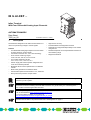
IB IL AI 4/EF ...
D
TR
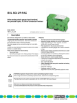
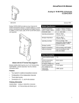
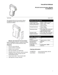
Inline Terminal
With Four Differential Analog Input Channels
Uis
AI
4/E
S
AUTOMATIONWORX
Data Sheet
7252_en_02
1
© PHOENIX CONTACT - 10/2006
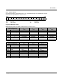
Description
The terminal is designed for use within an Inline station. It is
used to acquire analog voltage or current signals.
Features
–
–
–
–
–
–
–
–
–
Four differential analog signal inputs for the connection
of either voltage or current signals
Connection of sensors in 2, 3 or 4-wire technology
Three current measuring ranges:
0 mA to 20 mA, ±20 mA, 4 mA to 20 mA
Four voltage measuring ranges:
0 V to 10 V, ±10 V, 0 V to 5 V, ±5 V
Sensor supply with channel-specific integrated shortcircuit and overload protection
Measured values can be represented in four different
formats
Mean-value generation of measured values
Process data update of all channels in 1 ms, maximum
Bus-synchronous provision of input values
–
–
–
–
–
High level of accuracy
Parameterization and diagnostics via PCP
Channels are configured independently of one another
using the bus
Resolution depends on the representation format and
the measuring range
Diagnostic indicators
This data sheet is only valid in association with the IB IL SYS PRO UM E user manual or the Inline system
manual for your bus system.
The product versions differ in the scope of supply and the transmission speed (see "Ordering Data" on page 3).
The function is identical. Differing technical data is indicated. For greater clarity, the order designation
IB IL AI 4/EF is used throughout this document.
Make sure you always use the latest documentation.
It can be downloaded at www.download.phoenixcontact.com.
A conversion table is available on the Internet at
www.download.phoenixcontact.com/general/7000_en_00.pdf.
This data sheet is valid for all products listed under "Ordering Data" on page 3.
IB IL AI 4/EF ...
Table of Contents
1
Description.................................................................................................................................. 1
2
Ordering Data ............................................................................................................................. 3
3
Technical Data............................................................................................................................ 4
4
Local Diagnostic and Status Indicators and Terminal Point Assignment ................................... 8
4.1
4.2
4.3
Function Identification .................................................................................................................................... 8
Local Diagnostic and Status Indicators .......................................................................................................... 8
Terminal Point Assignment for Each Connector ............................................................................................ 8
5
Installation Instructions ............................................................................................................... 8
6
Internal Circuit Diagram.............................................................................................................. 9
7
Electrical Isolation......................................................................................................................10
8
Connection Notes ......................................................................................................................10
9
Connection Examples................................................................................................................10
10 Configuration and Analog Values ..............................................................................................13
11 Programming Data/Configuration Data ........................................................................................................ 13
11.1
11.2
INTERBUS ................................................................................................................................................... 13
Other Bus Systems ...................................................................................................................................... 13
12 Assignment of the Process Data to the Terminal Points for the
"Read Analog Value" and "Configure Device and Read Analog Value" Commands .................... 13
13 Process Data .............................................................................................................................14
14 OUT Process Data Words .........................................................................................................15
14.1
14.2
14.3
Output Word OUT1 (Control Word).............................................................................................................. 15
Output Words OUT2 to OUT5 (Configuration) ............................................................................................. 16
Parameters for Configuration ....................................................................................................................... 16
15 IN Process Data Words .............................................................................................................17
15.1
15.2
Input Word IN1 (Status Word)...................................................................................................................... 17
Input Words IN2 to IN5................................................................................................................................. 17
16 Formats for the Representation of Measured Values (IN2 to IN5) ............................................18
16.1
16.2
16.3
16.4
16.5
Format: "IB IL" (Default Setting)................................................................................................................... 18
Format: "IB ST" ............................................................................................................................................ 19
Format: "S7-Compatible" ............................................................................................................................. 20
Format: "Standardized Representation"....................................................................................................... 21
Supported Error Codes for the "IB IL" and "Standardized Display" Formats ............................................... 22
17 PCP Communication .................................................................................................................22
17.1
17.2
Object Dictionary.......................................................................................................................................... 22
Object Description........................................................................................................................................ 23
18 Diagnostics ................................................................................................................................25
7252_en_02
PHOENIX CONTACT
2
IB IL AI 4/EF ...
2
Ordering Data
Terminals
Description
Type
Order No.
Pcs./Pck.
Terminal with four analog input channels;
transmission speed of 500 kbps;
including accessories (connectors and labeling fields)
IB IL AI 4/EF-PAC
2878447
1
Terminal with four analog input channels;
transmission speed of 500 kbps; without accessories
IB IL AI 4/EF
2863478
1
Terminal with four analog input channels;
transmission speed of 2 Mbps;
including accessories (connectors and labeling fields)
IB IL AI 4/EF 2MBD-PAC
2878641
1
Terminal with four analog input channels;
transmission speed of 2 Mbps; without accessories
IB IL AI 4/EF 2MBD
2878544
1
The listed connector is needed for the complete fitting of the IB IL AI 4/EF terminal.
Accessories
Description
Type
Order No.
Pcs./Pck.
Connector with shield connection (green, without color print)
IB IL SCN-6 SHIELD
2726353
5
Documentation
Description
Type
Order No.
Pcs./Pck.
User manual:
"Configuring and Installing the INTERBUS Inline Product Range"
IB IL SYS PRO UM E
2743048
1
User manual:
"Automation Terminals of the Inline Product Range"
IL SYS INST UM E
2698737
1
7252_en_02
PHOENIX CONTACT
3
IB IL AI 4/EF ...
3
Technical Data
General Data
Housing dimensions (width x height x depth)
48.8 mm x 136.8 mm x 71.5 mm
Weight
125 g (without connectors)
Operating mode
Process data mode with 5 words/1 word PCP
Transmission speed
IB IL AI 4/EF-PAC, IB IL AI 4/EF
IB IL AI 4/EF 2MBD-PAC, IB IL AI 4/EF 2MBD
Connection method for sensors
500 kbps
2 Mbps
2, 3, and 4-wire technology (shielded)
Permissible temperature (operation)
-25°C to +55°C
Permissible temperature (storage/transport)
-25°C to +85°C
Permissible humidity (operation/storage/transport)
10% to 95%, according to DIN EN 61131-2
Permissible air pressure (operation/storage/transport)
70 kPa to 106 kPa (up to 3000 m above sea level)
Degree of protection
IP20 according to IEC 60529
Protection class
Class 3 according to VDE 0106, IEC 60536
Connection data for connector
Connection method
Spring-cage terminals
Conductor cross section
0.2 mm2 - 1.5 mm2 (solid or stranded), 24 - 16 AWG
Deviations From Common Technical Data That Are Indicated in the IB IL SYS PRO UM E User Manual
Noise Immunity Test According to EN 50082-2
Electrostatic discharge (ESD) according to EN 61000-4-2; IEC 61000-4-2
Criterion B
6 kV contact discharge
8 kV air discharge
Mechanical Requirements
Shock test according to EN 60068-2-27; IEC 60068-2-27
15g load for 11 ms, half sinusoidal wave,
three shocks in each space direction and orientation
25g load for 6 ms, half sinusoidal wave,
three shocks in each space direction and orientation
Interface
Local bus
Data routing
Power Consumption
500 kbps
Communications power UL
7.5 V
7.5 V
Current consumption from UL
85 mA (typical)/100 mA (maximum)
110 mA (typical)/125 mA (maximum)
2 Mbps
I/O supply voltage UANA
24 V DC
24 V DC
Current consumption at UANA
13 mA (typical)/20 mA (maximum)
13 mA (typical)/20 mA (maximum)
Total power consumption
950 mW (typical)/
1250 mW (maximum)
1140 mW (typical)/
1420 mW (maximum)
Supply of the Module Electronics and I/O Through the Bus Coupler/Power Terminal
Connection method
Potential routing
Sensor Supply Voltage UiS (via Supply of UM)
Nominal value UiS
24 V DC
Nominal current IIS per channel
50 mA
Protection
Internal, channel-specific electronic fuse, short-circuit-proof with singlechannel diagnostics
7252_en_02
PHOENIX CONTACT
4
IB IL AI 4/EF ...
Analog Inputs
Number
4 differential analog inputs
Signals/resolution in the process data word (quantization)
See tables on page 18 and onwards
Measured value representation
In the following formats:
IB IL
IB ST
S7-compatible
Standardized representation
(15 bits with sign bit)
(12 bits with sign bit)
(15 bits with sign bit)
(15 bits with sign bit)
Please read the notes on page 18 and page 21 on measured value representation in "IB IL" and "standardized representation" format.
Digital filtering (mean-value generation)
None or over 4, 16 or 32 measured values
Default setting: 16 measured values
Conversion time of the A/D converter
10 µs, maximum
Process data update of the channels
< 1 ms
Limit frequency (-3 dB) of the input filters
500 Hz
Bus synchronism
Yes
Transient protection
Yes, via arresters
Differential Analog Voltage Inputs
Number
4
Input range
0 V to 10 V; ±10 V; 0 V to 5 V; ±5 V
Input resistance
300 kΩ, approximately
Open circuit response
Goes to 0 V
Maximum permissible voltage between analog voltage inputs and functional
earth ground
±50 V DC
Differential Analog Current Inputs
Number
4
Input range
0 mA to 20 mA; ±20 mA; 4 mA to 20 mA
Input resistance
110 Ω, approximately (shunt)
Open circuit response
Goes to 0 mA
Maximum permissible current per current input
Overload protection
Maximum permissible voltage at the analog current inputs
±30 V
7252_en_02
PHOENIX CONTACT
5
IB IL AI 4/EF ...
Tolerance and Temperature Response
TA = 25°C
Measuring Range
Absolute (Typical)
Absolute (Maximum)
Relative (Typical)
Relative (Maximum)
0 V to 5 V
±5 V
±2.5 mV
±7.5 mV
±0.05%
±0.15%
0 V to 10 V
±10 V
±2.5 mV
±10 mV
±0.025%
±0.10%
0 mA to 20 mA
4 mA to 20 mA
±20 mA
±14 µA
±40 µA
±0.07%
±0.20%
TA = -25°C ... +55°C
Measuring Range
Absolute (Typical)
Absolute (Maximum)
Relative (Typical)
Relative (Maximum)
0 V to 5 V
±5 V
±9 mV
±20 mV
±0.18%
±0.40%
0 V to 10 V
±10 V
±13 mV
±30 mV
±0.13%
±0.30%
0 mA to 20 mA
4 mA to 20 mA
±20 mA
±22 µA
±80 µA
±0.11%
±0.40%
All percentage values refer to the relevant measuring range final value.
The values refer to nominal operation in the recommended mounting position (horizontal wall mounting).
Additional Tolerances Influenced by Electromagnetic Fields
Type of Electromagnetic Interference
Typical Deviation From the
Measuring Range Final Value
(Voltage Input)
Relative
Typical Deviation of the
Measuring Range Final Value
(Current Input)
Relative
Electromagnetic fields;
field strength 10 V/m
according to EN 61000-4-3/IEC 61000-4-3
< ±1%
< ±1%
Conducted interference
Class 3 (test voltage 10 V)
according to EN 61000-4-6/IEC 61000-4-6
< ±1%
< ±1%
Fast transients (burst)
4 kV supply, 2 kV input
according to EN 61000-4-4/IEC 61000-4-4
< ±1%
< ±1%
Safety Equipment
Inputs
Transient surge protection via arresters
Sensor supply voltage
Short-circuit protection with electronic fuse
Electrical Isolation/Isolation of the Voltage Areas
To provide electrical isolation between the logic level and the I/O area, it is necessary to supply the station bus coupler and the sensors
connected to the analog input terminal described here from separate power supply units. Interconnection of the power supply units in the
24 V area is not permitted. (See also user manual.)
Common Potentials
The 24 V main voltage, 24 V segment voltage, and GND have the same potential. FE is a separate potential area.
Separate Potentials in the System Consisting of Bus Coupler/Power Terminal and I/O Terminal
- Test Distance
- Test Voltage
7.5 V supply (bus logic), 24 V supply UANA/analog I/O
500 V AC, 50 Hz, 1 min.
7.5 V supply (bus logic), 24 V supply UANA/functional earth ground
500 V AC, 50 Hz, 1 min.
Analog I/O/functional earth ground
500 V AC, 50 Hz, 1 min.
7252_en_02
PHOENIX CONTACT
6
IB IL AI 4/EF ...
Error Messages to the Higher-Level Control or Computer System
Failure of the internal I/O voltage supply
Yes, I/O error message sent to the bus coupler
Failure of or insufficient communications power UL
Yes, I/O error message sent to the bus coupler
Peripheral fault/user error
Yes, error message via the IN process data (see page 17)
Approvals
For the latest approvals, please visit www.download.phoenixcontact.com.
7252_en_02
PHOENIX CONTACT
7
IB IL AI 4/EF ...
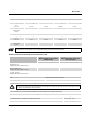
4
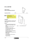
Local Diagnostic and Status Indicators and Terminal Point Assignment
4.1
Function Identification
Green
2 Mbps: White stripe in the vicinity of the D LED
D
TR
UiS
4.2
AI4EF
Des.
D
TR
UiS
D
TR
UiS
AI4E
F
1
1.1
1
1
2.1
1.2
2
2
2.2
1.3
3
3
2.3
1.4
4
4
2.4
IB IL AI 4/EF terminal
with an appropriate connector
Meaning
Diagnostics
PCP communication active
Sensor supply
Sensor supply present
Overload/short circuit of sensor
supply UiS or supply voltage UM
not present
UiS red ON/UM ON: Overload/short circuit of
the sensor supply UiS;
UiS red ON/UM OFF: Supply voltage UM not
present
4.3
Terminal Point Assignment for Each Connector
Terminal
Points
1.1
2.1
1.2
2.2
1.3
2.3
1.4, 2.4
5
Color
Green
Green
Green/red
Green ON
Red ON
If the UiS LED is red, please also check the
UM LED on the previous power terminal.
2
72520005
Figure 1
Local Diagnostic and Status Indicators
Signal
Assignment
UiSx (24 V) Initiator supply for channel x
GND
Ground for UiSx
Ux+
Positive voltage input for
channel x
UxMinus input for channel x
(voltage)
Ix+
Positive current input for
channel x
IxMinus input for channel x
(current)
Shield
Shield connection
x = 1 to 4
Installation Instructions
High current flowing through potential jumpers UM and US leads to a temperature rise in the potential jumpers and inside
the terminal. Observe the following instructions to keep the current flowing through the potential jumpers of the analog
terminals as low as possible:
Create a separate main circuit for each analog terminal.
If this is not possible in your application and you are using analog terminals in a main circuit together with other
terminals, place the analog terminals after all the other terminals at the end of the main circuit.
7252_en_02
PHOENIX CONTACT
8
IB IL AI 4/EF ...
6
Internal Circuit Diagram
Local Bus
OPC
UL+
UANA
UL24 V
µP
+-5 V
+- 15 V
EEPROM
+24 V (US)
+24 V (UM)
U1+
I1+
U1I1-
Uis2
U2+
I2+
GND
U2I2-
Uis3
U3+
I3+
GND
ELF
GND
ELF
Uis1
SUPERVISOR
MUX
ELF
ELF
REF
U3I3-
Uis4
GND
U4-
U4+
I4-
I4+
72520111
Figure 2
Internal wiring of the terminal points
Key:
OPC
Protocol chip
R E F
Reference voltage
x x x
Power supply unit with electrical isolation
Analog/digital converter
Optocoupler
Amplifier
X X X
µ P
Microprocessor
E E P R O M
Electrically erasable programmable readonly memory
S U P E R V IS O R
Microprocessor monitoring
M U X
Multiplexer
E L F
Electronic fuse
Resistor
Other symbols used are explained in the
IB IL SYS PRO UM E user manual or in the
Inline system manual for your bus system.
7252_en_02
PHOENIX CONTACT
9
IB IL AI 4/EF ...
7
Electrical Isolation
Local bus (IN)
OPC and
microprocessor
bus interface
UL (7.5 V DC)
9
Connection Examples
Use a connector with shield connection when
installing the sensors. Figure 4 shows the
connection schematically (without shield
connection).
Local bus(OUT)
UL (7.5 V DC)
UANA (24 V DC)
UANA (24 V DC)
24 V
5V
15 V
UM (24 V DC)
Peripheral
interface
24 V
A
B
UM (24 V DC)
Slot
Channel
Electrical isolation
between area A
and B
1
1
4
4
3
3
2
2
24 V
Analog inputs
FE potential
72520003
Figure 3
AI 4/EF
Connection Notes
1
Always connect the analog sensors using
shielded, twisted pair cables.
1
2
1
2
1
2
1
11
11
11
1
2
22
22
22
2
3
33
33
33
3
4
44
44
44
4
U1+
U1-
+24V
Connect the shielding to the terminal using the
shield connection clamp. The clamp connects
the shield to FE on the module side. Avoid
connection to FE from both sides.
2
I1+
I1-
8
D
TR
Uis
Electrical isolation of the individual function
areas
Voltage sensor
at channel 1
+24V
Uis (24 V DC)
Current sensor
at channel 4
72520004
Figure 4
7252_en_02
Connection of active sensors
in 4-wire technology with shield connection
PHOENIX CONTACT
10
IB IL AI 4/EF ...
1
2
1
1
2
2
3
3
4
4
24 V
I+
I
P
I-
GND
72520106
Figure 5
Passive pressure sensor at a differential current input
1
2
1
1
2
2
3
3
4
4
I+
I
P
I-
72520107
Figure 6
Active pressure sensor at a differential current input
1
2
1
1
2
2
3
3
4
4
24 V
I+
I
P
GND
72520108
Figure 7
Passive 2-wire transmitter at a differential current input
Set the jumper on the connector or alternatively in the sensor for 4-wire technology.
7252_en_02
PHOENIX CONTACT
11
IB IL AI 4/EF ...
24 V
1
2
1
1
2
2
3
3
4
4
U+
UDIFF
UUCM
GND
Figure 8
72520109
Passive voltage divider at a differential voltage input
Make sure that the voltage UCM does not exceed the specified range, see "Differential Analog Voltage Inputs"
on page 5.
1
2
24 V
1
1
2
2
P
3
3
GND
4
4
U+ U
72520110
Figure 9
Active 3-wire transmitter differential voltage input
Set the jumper on the connector.
7252_en_02
PHOENIX CONTACT
12
IB IL AI 4/EF ...
10
Configuration and Analog Values
You can either configure the device via process data or via
PCP and transmit analog values accordingly.
If the device was configured via PCP, the configuration can
no longer be modified the via process data.
11
Programming Data/Configuration
Data
11.1
INTERBUS
ID code
DFhex (223dec)
Length code
05hex
Input address area
5 words
Output address area
5 words
Parameter channel (PCP)
1 word
Register length (bus)
6 words
11.2
Other Bus Systems
For the programming data/configuration data
of other bus systems, please refer to the
corresponding electronic device data sheet
(e.g., GSD, EDS).
12
Assignment of the Process Data to the Terminal Points for the "Read Analog
Value" and "Configure Device and Read Analog Value" Commands
(Word.bit) view
Word
Bit
(Byte.bit) view
AI
Word 2:
Channel 1 (connector 1)
Word 3:
Channel 2 (connector 2)
Word 4:
Channel 3 (connector 3)
Word 5:
Channel 4 (connector 4)
7252_en_02
Word x
15 14 13 12 11 10 9
8
7
6
5
Byte 0
Byte
6
5
4
3
4
3
2
1
0
2
1
0
Byte 1
Bit
7
2
1
0
7
24 V
Terminal point 1.1: Sensor supply
GND
Terminal point 2.1: Ground
Signal
Terminal point 1.2: Positive voltage input
Terminal point 1.3: Positive current input
Signal reference
Terminal point 2.2: Negative voltage input
Terminal point 2.3: Negative current input
Shielding (FE)
Terminal point 1.4, 2.4
6
5
4
3
PHOENIX CONTACT
13
IB IL AI 4/EF ...
13
Process Data
The device has 5 process data words and 1 PCP word. The first output word represents the control word because the
assignment of the following words depends on the configuration. As confirmation for a control word action, the first input
word contains a partial copy of the control word.
For the device configuration, channel-specific configuration data is set in the relevant channel output words. Once
configuration has been completed, and depending on the format set, the measured values in the corresponding input words
are either transmitted to the controller board or to the computer.
O U T 1
C o n tro l w o rd
O U T 2
O U T 3
O U T 4
O U T 5
O U T
IN 1
S ta tu s w o rd
IN 2
IN 3
IN 4
IN 5
IN
Figure 10
7252_en_02
7 0 6 3 A 0 0 8
Order of the process data words
PHOENIX CONTACT
14
IB IL AI 4/EF ...
14
OUT Process Data Words
14.1
Output Word OUT1 (Control Word)
- For command code 400xhex and 500xhex ("Configure device" and "Read analog value")
OUT1
Bit
Assignment
15
14
Byte 0
13
12
11
10
Command code
9
8
7
0
6
0
5
0
Byte 1
4
3
0
0
6
0
5
0
Byte 1
4
3
0
0
2
0
1
0
0
PF
2
0
1
0
0
0
- For all other command codes
OUT1
Bit
Assignment
15
14
Byte 0
13
12
11
10
Command code
9
8
7
0
Bit 15 to bit 8 (command code)
Bit 15 to Bit 8
OUT1
0
0
0
0
0
0
0
0
0
0
1
0
0
C
0
0
1
1
1
1
0
0
1
0
0
0
0
0
0
1
0
1
0
0
0
Command Function
Read analog value.
0 0000hex
The analog value of the four input channels is represented in IN2 to IN5.
Read configuration.
The configuration of each channel is displayed channel-by-channel in
C 1x00hex
IN2.
C: Channel number: 00 - channel 1; 01 - channel 2; 10 - channel 3;
11 - channel 4
Read device data.
0 3C00hex The firmware version and the device identification number is displayed in
IN2, see "Input Words IN2 to IN5" on page 17.
Configure device.
0 400xhex
The channel parameters of the four channels are configured in OUT2 to
OUT5.
Configure device and read analog value.
0 500xhex
The channel parameters of the four channels are configured in OUT2 to
OUT5. The analog value of the four channels is represented in IN2 to IN5.
Bit 0
Bit 0
0
1
PF (Peripheral Fault in the Event of Sensor
Errors)
Not permitted (default)
Permitted
This bit is only significant for command codes 40hex and
50hex.
7252_en_02
PHOENIX CONTACT
15
IB IL AI 4/EF ...
14.2
Output Words OUT2 to OUT5 (Configuration)
Each channel can be configured independently of the other channels. The first channel is configured via the second output
word, the second channel via the third output word, etc.
If the configuration changes, the corresponding channel is re-initialized. If the format "IB IL" is set, the error code "Measured
value invalid" is output.
If the configuration is invalid, a corresponding error message is output in the status word. The configuration is stored in a
volatile memory.
For commands 400xhex and 500xhex, specify the parameters for the appropriate channels 1 to 4 in OUT2 to OUT5. The
parameter words are only evaluated by this command.
Bit
Assignment
14.3
15
0
14
0
13
0
12
0
11
0
10
0
OUTx (x = 2 to 5)
9
8
7
6
Filter
0
0
5
4
Format
3
2
1
0
Measuring range
Parameters for Configuration
The values displayed in bold are default settings.
Bit 9 and bit 8
Code (bin)
00
01
10
11
Filter
Mean value via 16 measured values
No mean value
Mean value via 4 measured values
Mean value via 32 measured values
Bit 5 and bit 4
Code (bin)
00
01
10
11
Format
IB IL (15 bits)
IB ST (12 bits)
S7-compatible
Standardized representation
Bit 3 to bit 0
Code (bin)
0000
0001
0010
0011
1000
1001
1010
7252_en_02
Code (hex)
0
1
2
3
8
9
A
4 to 7
B to F
Measuring Range
0 V to 10 V
±10 V
0 V to 5 V
±5 V
0 mA to 20 mA
±20 mA
4 mA to 20 mA
Reserved
PHOENIX CONTACT
16
IB IL AI 4/EF ...
15
IN Process Data Words
15.1
Input Word IN1 (Status Word)
OUT1
Bit
Assignment
15
EB
Byte 0
13
12
11
10
9
Mirrored command code*
14
8
7
0
6
0
5
0
Byte 1
4
3
0
0
2
0
1
0
0
0
Error bit:
EB = 0
EB = 1
No error has occurred.
An error has occurred.
The error bit is available as a group error message. Possible errors and their effects are listed in "Diagnostics" on page 25.
* Mirrored command codes:
A command code mirrored from the control word. Here, the MSB is suppressed.
15.2
Input Words IN2 to IN5
The measured values, firmware version or configuration are transmitted to the controller board or the computer via IN
process data words IN2 to IN5 according to the configuration.
For control words 0000hex and 5000hex (error-free standard operation) the measured values are transmitted in IN2 to IN5.
For control word 1x00hex, the configuration of the selected channel is indicated in IN2. For control word 3C00hex, IN2
supplies the firmware version and the device ID.
Example:
IN2
Bit
Assignment (hex)
Meaning
15
14
13
1
12
11
10
9
8
2
Firmware Version 1.23
7
6
5
3
4
3
2
1
0
6
Device ID
For control word 4000hex (configuration mode), the configuration data is mirrored in the input words after transfer.
7252_en_02
PHOENIX CONTACT
17
IB IL AI 4/EF ...
16
Formats for the Representation of Measured Values (IN2 to IN5)
16.1
Format: "IB IL" (Default Setting)
The measured value is represented in bits 14 to 0. An additional bit (bit 15) is available as a sign bit.
This format supports extended diagnostics. Values > 8000hex and < 8100hex indicate an error. The error codes are listed
on page 22.
Measured value representation in "IB IL" format (15 bits)
MSB
15
14
SB
SB
13
12
11
10
9
8
7
6
Analog value
5
4
3
2
1
LSB
0
Sign bit
Significant Measured Values
Measuring range 0 mA to 20 mA/4 mA to 20 mA/0 V to 5 V/0 V to 10 V
Input Data Word
(Two's Complement)
hex
dec
8001
Overrange
7F00
32512
7530
30000
0001
1
0000
0
8002
Open circuit
0 mA to 20 mA
IInput
mA
> +21.6746
+21.6746
+20.0
+0.66667 µA
≤
0
–
4 mA to 20 mA
IInput
mA
> +21.339733
+21.339733
+20.0
+4.00053333
+3.2 to +4.0
< +3.2
0 V to 5 V
UInput
V
> +5.419
+5.419
+5.0
+166.67 µV
≤
0
–
0 V to 10 V
UInput
V
> +10.837
+10.837
+10.0
+333.33 µV
≤
0
–
Measuring range -20 mA to +20 mA/-5 V to +5 V/-10 V to +10 V
Input Data Word
(Two's Complement)
hex
dec
8001
Overrange
7F00
32512
7530
30000
0001
1
0000
0
FFFF
-1
8AD0
-30000
8100
-32512
8080
Underrange
7252_en_02
-20 mA to +20 mA
-5 V to +5 V
IInput
UInput
mA
V
> +21.6746
> +5.419
+21.6746
+5.419
+20.0
+5.0
+0.66667 µA
+166.67 µV
0
0
-0.66667 µA
-166.67 µV
-20.0
-5.0
-21.6746
-5.419
< -21.6746
<
-5.419
-10 V to +10 V
UInput
V
> +10.837
+10.837
+10.0
+333.33 µV
0
-333.33 µV
-10.0
-10.837
< -10.837
PHOENIX CONTACT
18
IB IL AI 4/EF ...
16.2
Format: "IB ST"
The measured value is represented in bits 14 to 3. An additional bit (bit 15) is available as a sign bit.
Measured value representation in "IB ST" format
MSB
15
14
SB
SB
OC
13
12
11
10
9
8
7
Analog value
6
Sign bit
Open circuit
5
0
OR
4
3
2
0
1
OC
LSB
0
OR
Reserved
Overrange
Significant Measured Values
Measuring range 0 mA to 20 mA/4 mA to 20 mA/0 V to 5 V/0 V to 10 V
Input Data Word
(Two's Complement)
hex
dec
7FF9
Overrange
7FF8
32760
7FF8
32760
4000
16384
0008
8
0000
0
0002
Open circuit
0 mA to 20 mA
IInput
mA
> +21.5
+20.0 to +21.5
+19.9951
+10
+0.0048828
≤
0
–
4 mA to 20 mA
IInput
mA
> +21.5
+20.0 to +21.5
+19.9961
+12.0
+4.003906
+3.2 to +4.0
< +3.2
>
≤
0 V to 5 V
UInput
V
+5.375
+5.0 to +5.375
+4.9988
+2.5
+0.001221
0
–
0 V to 10 V
UInput
V
> +10.75
+10.0 to +10.75
+9.9975
+5.0
+0.002441
≤
0
–
Measuring range -20 mA to +20 mA/-5 V to +5 V/-10 V to +10 V
Input Data Word
(Two's Complement)
hex
dec
7FF9 Overrange
7FF8 32760
7FF8 32760
4000
16384
0008
8
0000
0
FFF8 -8
8000
-32768
8001
-32767
7252_en_02
-20 mA to +20 mA
IInput
mA
> +21.5
>
+20.0 to +21.5
+19.9951
+10.0
+0.0048828
0
-0.0048828
-20.0 to -21.5
< -21.5
<
-5 V to +5 V
-10 V to +10 V
UInput
UInput
V
V
+5.375
> +10.75
+5.00 to +5.375
+10.0 to +10.75
+4.9988
+9.9975
+2.5
+5.0
+0.001221
0.002441
0
0
-0.001221
-0.002441
-5.0 to -5.375
-10.0 to -10.75
-5.375
< -10.75
PHOENIX CONTACT
19
IB IL AI 4/EF ...
16.3
Format: "S7-Compatible"
The measured value is represented in bits 14 to 0. An additional bit (bit 15) is available as a sign bit.
Measured value representation in "S7-compatible" format
MSB
15
14
SB
SB
13
12
11
10
9
8
7
6
Analog value
5
4
3
2
1
LSB
0
Sign bit
Significant Measured Values
Measuring range 0 mA to 20 mA/4 mA to 20 mA/0 V to 5 V/0 V to 10 V
Input Data Word
(Two's Complement)
hex
dec
7FFF
Overrange
7EFF
32511
6C00
27648
0001
1
0000
0
8000
Underrange
0 mA to 20 mA
IInput
mA
> +23.5157
+23.5157
+20.0
+0.7234 µA
≤
0
–
4 mA to 20 mA
IInput
mA
> +22.8142
+22.8142
+20.0
+4.0005787
+4.0
< +1.11852
0 V to 5 V
UInput
V
> +5.879
+5.879
+5.0
+180.85 µV
≤
0
–
0 V to 10 V
UInput
V
> +11.759
+11.759
+10.00
+361.39 µV
≤
0
–
Measuring range -20 mA to +20 mA/-5 V to +5 V/-10 V to +10 V
Input Data Word
(Two's Complement)
hex
dec
7FFF
Overrange
7EFF
32511
6C00
27648
0001
1
0000
0
FFFF
-1
9400
-27648
8100
-32512
8000
Underrange
-20 mA to +20 mA
-5 V to +5 V
IInput
UInput
mA
V
> +23.5157
> +5.879
+23.5157
+5.879
+20.00
+5.0
+0.7234 µA
+180.85 µA
0
0
-0.7234 µA
-180.85 µA
-20.0
-5.0
-23.516
-5.879
< -23.516
<
-5.879
-10 V to +10 V
UInput
V
> +11.759
+11.759
+10.0
+361.69
0
-361.69
-10.0
-11.759
< -11.759
Formula for Calculating the Measured Value From the Process Data Input Value for the 4 mA to 20 mA Measuring
Range
Measured value = Process data input value x 0.0005787 mA + 4 mA
Process data input value
Value x resolution
+ 4 mA
Measured value
7252_en_02
Example 1
6C00hex = 27648dec
27648 x 0.0005787 mA = 16 mA
16 mA + 4 mA = 20 mA
20 mA
Example 2
F940hex -> FFFFhex - F940hex + 1 = -1728dec
-1728 x 0.0005787 mA = -1 mA
-1 mA + 4 mA = 3 mA
3 mA
PHOENIX CONTACT
20
IB IL AI 4/EF ...
16.4
Format: "Standardized Representation"
The data is represented in bits 14 to 0. An additional bit (bit 15) is available as a sign bit.
In this format, data is standardized to the measuring range and represented in such a way that it indicates the corresponding
value without conversion. In this format one bit has the value of 1 mV or 1 µA.
This format supports extended diagnostics. Values > 8000hex and < 8100hex indicate an error. The error codes are listed
on page 22.
Measured value representation in "standardized representation" format
MSB
15
14
SB
SB
13
12
11
10
9
8
7
6
Analog value
5
4
3
2
1
LSB
0
Sign bit
Significant Measured Values
Measuring range 0 mA to 20 mA/4 mA to 20 mA/0 V to 5 V/0 V to 10 V
Input Data Word
(Two's Complement)
hex
dec
8001
Overrange
4E20 20000
2710
10000
1388
5000
0001
1
0000
0
8002
Open circuit
0 mA to 20 mA
IInput
mA
> +21.6747
+20.0
+10.0
+5.0
+0.001
≤
0
–
4 mA to 20 mA
IInput
mA
> +21.339
–
+14.0
+9.0
+4.001
+4.0 to +3.2
< +3.2
>
≤
0 V to 5 V
UInput
V
+5.419
–
–
+5.0
+0.001
0
–
0 V to 10 V
UInput
V
> +10.837
–
+10.00
+5.0
+0.001
≤
0
–
Measuring range -20 mA to +20 mA/-5 V to +5 V/-10 V to +10 V
Input Data Word
(Two's Complement)
hex
dec
8001
Overrange
4E20
20000
2710
10000
1388
5000
0001
1
0000
0
FFFF
-1
EC78
-5000
D8F0
-10000
B1E0
-20000
8080
Underrange
7252_en_02
-20 mA to +20 mA
IInput
mA
> +21.6747
>
+20.0
+10.0
+5.0
0.001
0
-0.001
-5.0
-10.0
-20.0
< -21.6747
<
-5 V to +5 V
UInput
V
+5.419
–
–
+5.0
+0.001
0
-0.001
-5.0
–
–
-5.419
-10 V to +10 V
UInput
V
> +10.837
–
+10.0
+5.0
+0.001
0
-0.001
-5.0
-10.0
–
< -10.837
PHOENIX CONTACT
21
IB IL AI 4/EF ...
16.5
Supported Error Codes for the "IB IL" and "Standardized Display" Formats
After an error message, the following errors/messages for "IB IL" and "standardized representation" format are displayed
in words IN2 to IN5 in the status word (error bit):
Supported Error Codes in "IB IL" Format
Input Data Word (hex)
8001
8002
8004
8020
8040
8080
17
Error
Overrange
Open circuit
Measured value invalid
Sensor and/or analog supply not present
Device faulty
Underrange
PCP Communication
For information on PCP communication, please refer to the IBS SYS PCP G4 UM E
(Order No. 2745169) and IBS PCP COMPACT UM E (Order No. 9015349) user manuals.
By default upon delivery, the device is configured according to the default settings listed on page 16. The device can be
configured to suit your application using process data or PCP.
In PCP mode, the device is configured with the "Config Table" object.
The IBS CMD (for standard controller boards) and PC WorX (for Field Controllers (FC) and Remote Field
Controllers (RFC)) programs are available for the configuration and parameterization of your INTERBUS
system.
For additional information, please refer to the "IBS CMD SWT G4 UM E" (Order No. 2722250) user manual and
the documention for your applied PC WorX version.
17.1
Object Dictionary
Index
0080hex
0081hex
N:
L:
Data Type
Array of Unsigned 16
Array of Unsigned 16
Number of elements
Length of an element in bytes
7252_en_02
N
5
4
L
2
2
Meaning
rd:
wr:
Read access permitted
Write access permitted
Object Name
Config Table
Analog Values
Rights
rd/wr
rd
PHOENIX CONTACT
22
IB IL AI 4/EF ...
17.2
Object Description
Config Table Object
Configure the device using this object.
Object description:
Object
Config Table
Access
Read, write
Data type
Array of Unsigned 16
Index
0080hex
Subindex
00hex
01hex
02hex
03hex
04hex
05hex
Write all elements
Configuration channel 1
Configuration channel 2
Configuration channel 3
Configuration channel 4
System bits
Length (bytes)
0Ahex
02hex
Subindex 00hex
Subindex 01hex to 05hex
Data
Device configuration
5 x 2 bytes
Element Value Range
The "Configuration channel x" elements have the following structure:
Bit
Assignment
15
0
14
0
13
0
12
0
11
0
10
0
9
8
Filter
7
0
6
0
5
4
Format
3
2
1
Output range
0
For the value ranges for the individual parameters, please refer to "Parameters for Configuration" on page 16.
The "System bits" element has the following structure:
Bit
Assignment
15
0
14
0
13
0
12
0
11
0
10
0
9
0
8
0
7
0
6
0
5
0
4
0
3
0
2
PF
1
0
0
Conf
"PF"
If bit 2 = 1, a peripheral fault is generated in the event of a sensor problem (overrange, underrange, open circuit).
"Conf"
If bit 0 = 1, configuration via process data is permitted (command code 400xhex or 500xhex).
If an invalid configuration is specified, a negative confirmation is generated with error message 08hex, 00hex or xx30hex. The
low byte of the additional error code is 30hex (value is out of range), the high byte contains the number of the affected
element.
Example: Config Table is completely written with data (subindex 00) and the entry for channel 2 is invalid. In this case, the
additional error code is equal to 0230hex.
7252_en_02
PHOENIX CONTACT
23
IB IL AI 4/EF ...
Analog Values Object
The elements of this object contain the analog values of the channels in the format that was selected for this channel.
Object description:
Object
Analog Values
Access
Read
Data type
Array of Unsigned 16
Index
0081hex
Subindex
00hex
01hex
02hex
03hex
04hex
Read all elements
Analog value channel 1
Analog value channel 2
Analog value channel 3
Analog value channel 4
Length (bytes)
08hex
02hex
Subindex 00hex
Subindex 01hex to 04hex
Data
Analog values of the channels
4 x 2 bytes
DiagState Object
The elements of this object contain the current diagnostic status of the device.
Object description:
Object
DiagState
Access
Read
Data type
Record
Index
0018hex
Subindex
00hex
Read all elements
01hex
Consecutive no.
02hex
Priority
Unsigned 8 (1 byte)
03hex
Channel
Unsigned 8 (1 byte)
04hex
Code
Unsigned 16 (2 bytes)
05hex
MoreFollows
Unsigned 8 (1 byte)
OctetString (10 bytes)
06hex
Text
Length (bytes)
11hex
01hex
02hex
0Ahex
Subindex 00hex
Subindex 02hex, 03hex, 05hex
Subindex 01hex, 04hex
Subindex 06hex
Data
Diagnostic status of the device
7252_en_02
Unsigned 16 (2 bytes)
PHOENIX CONTACT
24
IB IL AI 4/EF ...
Consecutive no.
Priority
Channel
Code
MoreFollows
Text
18
Meaning
Possible Values
Unique, consecutive error number since the last 0 to 65535
power up reset or history reset
Priority of the message
If Code = 0000hex, Priority = 00hex
otherwise Priority = 02hex
If Code = 0000hex, Channel = 00hex
otherwise Channel = 01hex to 04hex
Error code
0000hex: No error
8910hex: Overrange
8920hex: Underrange
7710hex: Cable break
5160hex: Power supply error
5010hex: Hardware fault
00hex = No additional information is available for 00hex
this error.
The first 10 characters of the status message. If Code = 0000hex,
Default: "Status OK"
Text = "Status OK"
otherwise text contains error-specific
information
Diagnostics
The following events are monitored and indicated:
Event
Open circuit,
overrange and underrange of the
measuring range
Voltage failure of the sensor supply
Voltage failure of the internal analog
device supply (5 V and 15 V)
Faulty configuration
Response
– Error bit set
– Indication of an error code in the measured value
(only for "IB IL" and "standardized representation" format)
– Generation of a peripheral fault, if this was permitted during configuration
– Error bit set
– Device error
– Indication of an error code in the measured value
(only for "IB IL" and "standardized representation" format)
– Generation of a peripheral fault, if this was permitted during configuration
– Error bit set
– Indication of an error code in the measured value
(only for "IB IL" and "standardized representation" format)
– Generation of a peripheral fault, if this was permitted during configuration
– Error bit set
© PHOENIX CONTACT 10/2006
7252_en_02
PHOENIX CONTACT GmbH & Co. KG • 32823 Blomberg • Germany
Phone: +49-(0) 5235-3-00 • Fax: +49-(0) 5235-3-4 12 00
www.phoenixcontact.com
25