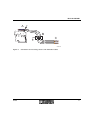
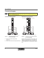
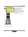
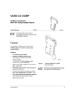
1
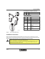
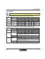
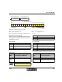
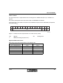
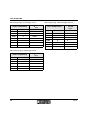
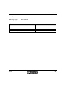
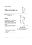
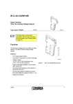
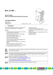
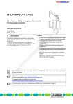
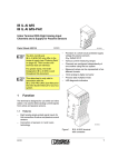
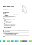
IB IL AI 2/SF-ME
Inline Terminal
With Two Analog Input Channels
Data Sheet 703700
04/2004
5 5 6 4 B 0 0 1
This data sheet is only valid in
association with the
IB IL SYS PRO UM E user manual or
the Inline system manual for your bus
system.
Function
The terminal is designed for use within an Inline
station. It is used to acquire analog voltage or
current signals.
Features
–
Two analog single-ended signal inputs for
the connection of either voltage or current
signals
–
Sensors are connected using 2-wire
technology
–
Three current measuring ranges:
0 mA to 20 mA, ±20 mA, 4 mA to 20 mA
–
Two voltage measuring ranges:
0 V to 10 V, ±10 V
–
Channels are configured independently of
one another using the bus
–
Measured values can be represented in four
different formats
–
12-bit resolution
–
Process data update of both channels in
1.5 ms, maximum
–
Diagnostic indicator
703700
5 5 6 4 C 0 1 0
Figure 1
IB IL AI 2/SF-ME terminal
1
IB IL AI 2/SF-ME
Table of Contents
Function ........................................................................................................................................... 1
Table of Contents ............................................................................................................................. 2
Installation Instructions...................................................................................................................... 3
Internal Circuit Diagram ................................................................................................................... 4
Electrical Isolation ............................................................................................................................5
Connection Notes ............................................................................................................................. 5
Connection Examples ...................................................................................................................... 8
Programming Data/Configuration Data ........................................................................................... 10
Process Data................................................................................................................................... 11
Formats for Representing Measured Values ................................................................................. 15
Technical Data ............................................................................................................................... 24
Ordering Data.................................................................................................................................. 29
2
703700
IB IL AI 2/SF-ME
Local Diagnostic and Status Indicators
Des.
D
D
Color Meaning
Green Diagnostics
A I2
Terminal Assignment
1
2
1 .1
1
1
2 .1
1 .2
2
2
2 .2
1 .3
3
3
2 .3
1 .4
4
4
2 .4
Terminal Signal
Points
Assignment
1.1
+U1
Voltage input channel 1
2.1
+U2
Voltage input channel 2
1.2
+I1
Current input channel 1
2.2
+I2
Current input channel 2
1.3
-1
Minus input for channel 1
(common for current and
voltage)
2.3
-2
Minus input for channel 2
(common for current and
voltage)
1.4, 2.4
Shield
Shield connection
5 5 6 4 C 0 0 2
Figure 2
IB IL AI 2/SF-ME terminal
Installation Instructions
High current flowing through the potential jumpers UM and US leads to a temperature rise of the
potential jumpers and the inside of the terminal. Observe the following instructions to keep the current
flowing through the potential jumpers of the analog terminals as low as possible:
Create a separate main circuit for the analog terminals.
If this is not possible in your application and you are using analog terminals in a main
circuit together with other terminals, place the analog terminals behind all the other
terminals at the end of the main circuit.
703700
3
IB IL AI 2/SF-ME
Internal Circuit Diagram
Key:
L o c a l b u s
O P C
OPC
U
U
U
Protocol chip
L +
A N A
L -
Optocoupler
2 4 V
x x x
X X X
+ 5 V
/ + 1 0 V
µ P
M U X
µ P
M U X
R E F
E E P R O M
+ 2 4 V (U M )
U
IN
I IN
1
U
4
Reference voltage
Electrically erasable
programmable read-only memory
Amplifier
IN
I IN
Coupling network
2
5 5 6 4 C 0 0 3
Figure 3
Microprocessor with multiplexer
and analog-to-digital converter
R E F
E E P R O M
+ 2 4 V (U S )
Power supply unit with electrical
isolation
Other symbols used are explained in
the IB IL SYS PRO UM E user
manual or in the Inline system
manual for your bus system.
Internal wiring of the terminal points
703700
IB IL AI 2/SF-ME
Electrical Isolation
L o c a l b u s (IN )
U
L
B u s c o n n e c tio n
O P C
(7 .5 V D C )
L o c a l b u s (O U T )
U
L
U
U
A N A
(2 4 V D C )
2 4 V
5 V
1 0 V
5 V
1 0 V
F E p o te n tia l
Figure 4
(7 .5 V D C )
A N A
(2 4 V D C )
A
I/O
in te r fa c e
a n d
m ic r o p r o c e s s o r
A n a lo g in p u ts
B
E le c tr ic a l is o la tio n
b e tw e e n a re a s
A a n d B
5 5 6 4 B 0 1 1
Electrical isolation of the individual
function areas
Connection Notes
Do not connect voltages exceeding ±5 V to a current input. This damages the module
electronics as the maximum permissible current of ±100 mA is exceeded.
Always connect the analog sensors using shielded, twisted pair cables.
Connect the shielding of the sensor with PE potential.
When using cables > 1 m (3.28 ft.) fold the outer cable sheath back and connect the shield
to the terminal via the contacts 1.4 or 2.4. These contacts connect the shield directly to FE
(functional earth ground) on the terminal side.
Additional wiring is not necessary.
703700
5
IB IL AI 2/SF-ME
Within the terminal, ground is connected to FE via an RC-element.
A
B
5 5 2 0 A 0 4 3
Figure 5
Connection of analog sensors, signal cables
If you want to use both channels of the IB IL AI 2/SF-ME terminal, you can connect the
shield in various ways depending on the cable feed.
1
If one multi-wire cable is used to connect
both sensors, connect the shielding as
described above (see Figure 5).
2
If two individual cables are used to connect
the sensors, proceed as follows to prevent
ground loops (see Figure 6):
6
•
Install a busbar with a connection to the ground potential in front of the Inline terminal (detail
B in Figure 6). Fold back the outer sheath of the two cables at the appropriate position and
connect the shields of both cables, e.g., using an SK shield clamp ( see "CLIPLINE" catalog).
The busbar must be the only point at which the shield of every cable is connected to ground
potential.
•
Lead the cables to the Inline terminal and connect the shield, as described above, to the
terminal points 1.4 and 2.4. (Detail A in Figure 5).
•
Lead the sensor cable into the sensor making sure to maintain the integrity of the cable
insulation (detail C in Figure 6).
703700
IB IL AI 2/SF-ME
A
B
C
5 5 2 0 B 1 1 8
Figure 6
703700
Connection of two analog sensors with individual cables
7
IB IL AI 2/SF-ME
Connection Examples
Figure 7 and Figure 8 show the connection schematically (without shield connector). One
side of the shielding must be connected at the sensor or at an appropriate point to the
functional earth ground potential.
Connection of Passive Sensors
IB IL 2 4 S E G /F
D
IB IL A I 2 /S F -M E
S E G /F
A I2
1
1
2
Figure 7
2
1
2
1
2
2
2
2 2
2
3
3
3
3 3
3
4
4
4
4 4
4
IN
B
5 5 6 4 A 0 0 4
Connection of active sensors
in 2-wire technology
Active sensor with voltage output
(channel 1)
B
Active sensor with current output (channel 2)
IN
1 1
IN
1
2 4 V
1
A
8
A I2
1
IN
A
D
U S
U M
2 4 V
Connection of Active Sensors
5 5 6 4 B 0 0 5
Figure 8
Connection of two passive sensors
in 2-wire technology
Figure 8 shows the passive sensor supply. The
sensors are supplied through a pre-connected
segment terminal with a fuse. The sensors can
also be supplied from an external power supply
unit.
703700
IB IL AI 2/SF-ME
Connection for Battery Monitoring
Both reference inputs (minus inputs)
of each IB IL AI 2/SF-ME terminal are
connected to each other. If signal
sources are connected in series,
wrong connections can lead to a
short circuit of individual signal
sources.
Because of the single-ended inputs, the
following connections are necessary:
Connect the reference input of a terminal
between two voltage sources.
Channel 1 measures the first voltage source
with opposite polarity. The measured value must
be adapted in the control system to the polarity.
Channel 2 measures the second voltage source
with correct polarity.
Configure the terminal to bipolar (±10 V).
D
D
A I2
1
2 V
D
A I2
2
1
A I2
2
703700
2
1
1 1
1 1
1
2
2 2
2 2
2
3
3 3
3 3
3
4
4 4
4 4
4
2 V
2 V
2 V
1 2 V
Figure 9
1
2 V
2 V
5 5 6 4 A 0 1 2
Connection for battery monitoring
9
IB IL AI 2/SF-ME
Programming Data/
Configuration Data
INTERBUS
ID code
7Fhex (127dec)
Length code
02hex
Input address area
4 bytes
Output address area
4 bytes
Parameter channel
(PCP)
0 bytes
Register length (bus)
4 bytes
Other Bus Systems
For the programming data/
configuration data of other bus
systems, please refer to the
corresponding electronic device data
sheet (GSD, EDS).
10
703700
IB IL AI 2/SF-ME
Process Data
For the assignment of the illustrated (byte.bit) view to your INTERBUS control or computer
system, please refer to the data sheet DB GB IBS SYS ADDRESS Order No. 90 00 99 0.
OUT Process Data Words for the Configuration of the Terminal (see page 13)
(Word.bit)
view
Byte
Bit
Word 0
15 14 13 12 11 10 9
8
7
6
5
4
3
2
1
0
2
1
0
(Byte.bit)
view
Byte
Bit
7
6
5
4
3
2
1
0
7
6
5
Channel 1
Assignment
1
0
0
0
0
0
Filter
0
0
Format Measuring
range
Channel 2
Assignment
1
0
0
0
0
0
Filter
0
0
Format Measuring
range
Byte 0
Byte 1
4
3
Assignment of the Terminal Points to the IN Process Data Words (see page 14)
(Word.bit)
view
Byte
(Byte.bit)
view
Byte
Bit
7
1
0
7
6
5
4
Channel 1
Signal
15 14 13 12 11 10 9
8
7
6
5
7
6
5
Bit
Word 0
15 14 13 12 11 10 9
8
7
6
5
Byte 0
6
5
4
3
4
3
2
1
0
3
2
1
0
4
3
2
1
0
4
3
2
1
0
Byte 1
2
Terminal point 1.1: voltage input
Terminal point 1.2: current input
Signal reference Terminal point 1.3
Channel 2
Shielding (FE)
Terminal point 1.4
Signal
15 14 13 12 11 10 9
8
Terminal point 2.1: voltage input
Terminal point 2.2: current input
Signal reference Terminal point 2.3
Shielding
703700
Terminal point 2.4
11
IB IL AI 2/SF-ME
OUT Process Data Words
With the two OUT process data words you can
configure each channel of the terminal
independently. The following configurations are
possible:
–
Selecting a measuring range according to
the input signal
–
Switching off average value generation
–
Changing the formats of the measured value
representation
The configuration settings are not saved. It must
be transmitted in each bus cycle.
After applying voltage (power up) to the Inline
station, the "Measured value invalid" message
(error code 8004hex) appears in the IN process
data words. After 1 second, maximum, the
preset configuration is accepted and the first
measured value is available. If you change the
configuration the corresponding channel is reinitialized. The "Measured value invalid"
message (error code 8004hex) appears in the
OUT process data words for 100 ms, maximum.
12
Default:
Measuring range:
0 V to 10 V
Average value
generation:
Switched on
Output format:
IL format
You cannot change the signal input
type through the OUT process data
words. Current or voltage
measurement is selected by applying
the measured signal to the current or
voltage input.
In addition, select the corresponding
measuring range through the OUT
process data words.
Do not simultaneously apply current
and voltage signals to an input
channel as you will not obtain valid
measured values.
703700
IB IL AI 2/SF-ME
P ro c e s s d a ta w o rd 1
P ro c e s s d a ta w o rd 2
C h a n n e l 1
C h a n n e l 2
M S B
L S B
1 4
1 5
1 3
1 2
1 1
C o n fig u r a tio n
1 0
9
8
7
6
F ilte r
5
4
3
F o rm a t
2
1
0
M e a s u r in g r a n g e
5 5 6 4 0 0 0 6
Figure 10 OUT process data words
MSB
Most significant bit
One OUT process data word is available for the
configuration of each channel.
Set bit 15 of the corresponding output word to 1
to configure the terminal. If bit 15 = 0 the preset
configuration is active.
Bit 9 and bit 8:
LSB
Least significant bit
Bit 15:
Code
Configuration
0
Default
1
Configuration data
Bit 5 and bit 4:
Code
Filter
Code
Format
00
16-sample average value (default)
00
IB IL (12 bits) (default)
01
No filter
01
IB ST (12 bits)
10, 11
Reserved
10
IB RT (12 bits)
11
Standardized display
Bit 3 to bit 0:
Code
Measuring Range (Voltage)
Code
Measuring Range (Current)
0000
0 V through 10 V (default)
1000
0 mA through 20 mA
0001
±10 V
1001
±20 mA
0010
through
0111
Reserved
1010
4 mA through 20 mA
1011 through
1111
Reserved
Set all reserved bits to 0.
703700
13
IB IL AI 2/SF-ME
IN Process Data Words
The measured values are transmitted, per channel, to the controller board or the computer by means
of the IN process data words.
P ro c e s s d a ta w o rd 2
P ro c e s s d a ta w o rd 1
C h a n n e l 1
C h a n n e l 2
F o rm a t:
M S B
1 5
L S B
1 4
1 3
1 2
1 1
1 0
9
7
6
5
4
3
2
A V
S B
1 5
8
1 4
1 3
1 2
1 1
1 0
9
1
x
8
7
6
5
4
3
0
x
x
2
1
0
0 /4
O C
O R
IL
R T
S ta n d a r d iz e d
d is p la y
S T
A V
S B
5 5 6 4 B 0 0 9
Figure 11 Sequence of the IN process data words and display of the bits of the first process data
word in the different formats
SB
Sign bit
OC
Open circuit
AV
Analog value
OR
Overrange
0/4
Measuring range 4 through 20 mA
x
Without meaning (may be 0 or 1)
MSB
Most significant bit
LSB
Least significant bit
The "IB IL" and "standardized display" process data formats support extended diagnostics. The
following error codes are possible:
Code (hex)
Error
8001
Overrange
8002
Open circuit
8004
Measured value invalid/no valid measured value
available
8010
Configuration invalid
8040
Module faulty
8080
Underrange
14
703700
IB IL AI 2/SF-ME
Formats for Representing the Measured Values
"IB IL" Format
The measured value is represented in bits 14 through 3. An additional bit (bit 15) is available as a
sign bit.
This format supports extended diagnostics. Values >8000hex indicate an error. The error codes are
listed on page 14.
1 5
1 4
1 3
1 2
1 1
1 0
9
8
7
6
5
4
3
A V
S B
2
1
x
x
0
x
5 5 6 4 A 0 0 8
Figure 12 Measured value representation in "IB IL" format (12 bits)
SB
Sign bit
AV
x
Without meaning (may be 0 or 1)
Analog value
This format is preset (default). To ensure that the terminal can be operated in previously used data
formats, the measured value representation can be switched to different formats.
Significant Measured Values
Some codes are used for diagnostic functions. In this case, take the complete 16-bit value into
account.
Measuring range 0 mA through 20 mA / 0 V through 10 V
Input Data Word
(Two’s Complement)
hex
dec
8001
Overrange
7F00
0 mA to 20 mA
IInput
0 V to 10 V
UInput
mA
V
> +21.675
> +10.837
32512
+21.675
+10.837
7530
30000
+20.0
+10.0
0008
8
0000
0
0000
0
703700
+5.33 µA
+2.667 mV
0
<
0
0
<
0
15
IB IL AI 2/SF-ME
Measuring range -20 mA through +20 mA / -10 V through +10 V
Input Data Word
(Two’s Complement)
hex
dec
8001
Overrange
7F00
-20 mA to +20 mA
IInput
-10 V to +10 V
UInput
mA
V
> +21.675
> +10.837
32512
+21.675
+10.837
7530
30000
+20.0
+10.0
0008
8
0000
0
FFF8
-8
8AD0
-30000
-20.0
-10.0
8100
-32000
-21.675
-10.837
8080
Underrange
< -21.675
< -10.837
+5.33 µA
0
+2.667 mV
0
-5.33 µA
-2.667 mV
Measuring range 4 mA through 20 mA
Input Data Word
(Two’s Complement)
16
4 mA to 20 mA
IInput
hex
dec
mA
8001
Overrange
7F00
32512
+21.3397
7530
30000
+20.0
0008
8
+4.004267
0000
0
+4.0 to 3.2
8002
Open circuit
> +21.3397
< +3.2
703700
IB IL AI 2/SF-ME
"IB ST" Format
The measured value is represented in bits 14 through 3. The remaining 4 bits are available as sign,
measuring range and error bits.
This format corresponds to the data format used on INTERBUS ST modules.
1 5
1 4
1 3
1 2
1 1
1 0
9
8
7
6
5
4
3
A V
S B
2
1
0
0 /4
O C
O R
5 5 6 4 0 0 0 7
Figure 13 Measured value representation in "IB ST" format (12 bits)
SB
Sign bit
OC
Open circuit
AV
Analog value
OR
Overrange
0/4
Measuring range 4 through 20 mA
Significant Measured Values
Measuring range 0 mA through 20 mA / 0 V through 10 V
Input Data Word
(Two’s Complement)
0 mA to 20 mA
IInput
0 V to 10 V
UInput
hex
mA
V
7FF9
703700
> 21.5
> 10.75
7FF8
20.0 to 21.5
10.00 to 10.75
7FF8
19.9951
9.9975
4000
10.0
5.0
0008
0.0048828
0.002441
0000
0
0
17
IB IL AI 2/SF-ME
Measuring range -20 mA through +20 mA / -10 V through +10 V
Input Data Word
(Two’s Complement)
-20 mA to +20 mA
IInput
-10 V to +10 V
UInput
hex
mA
V
7FF9
> 21.5
> 10.75
7FF8
20.0 to 21.5
7FF8
19.9951
10.00 to 10.75
9.9975
0008
0.0048828
0.002441
0000
0
0
FFF8
-0.0048828
8000
-20.0 to -21.5
8001
< -21.5
-0.002441
-10.00 to -10.75
< -10.75
Measuring range 4 mA through 20 mA
Input Data Word
(Two’s Complement)
4 mA to 20 mA
IInput
hex
mA
7FFD
7FFC
20.0 to 21.5
7FFC
19.9961
000C
4.003906
0004
3.2 to 4.0
0006
18
> 21.5
<
3.2
703700
IB IL AI 2/SF-ME
"IB RT" Format
The measured value is represented in bits 14 through 0. An additional bit (bit 15) is available as a
sign bit.
This format corresponds to the data format used on INTERBUS RT modules.
In this data format error codes or error bits are not defined. An open circuit is indicated by the positive
final value 7FFFhex.
1 5
1 4
1 3
1 2
1 1
1 0
9
8
7
6
5
4
3
A V
S B
2
1
x
x
0
x
5 5 6 4 A 0 0 8
Figure 14 Measured value representation in "IB RT" format (15 bits)
SB
Sign bit
AV
x
Without meaning (may be 0 or 1)
Analog value
Significant Measured Values
Measuring range 0 mA through 20 mA / 0 V through 10 V
Input Data Word
(Two’s Complement)
0 mA to 20 mA
IInput
0 V to 10 V
UInput
hex
mA
V
7FF8
≥ 19.9951
4000
10.0
0008
0000
703700
≥
5.0
4.88 µA
≤
0
9.9976
2.447 mV
≤
0
19
IB IL AI 2/SF-ME
Measuring range -20 mA through +20 mA / -10 V through +10 V
Input Data Word
(Two’s Complement)
-20 mA to +20 mA
IInput
-10 V to +10 V
UInput
hex
mA
V
7FF8
+19.9951
+9.9976
4000
+10.0
+5.0
0008
0000
+4.883 µA
0
0
FFF8
-4.883 µA
8008
-19.999389
8000
+2.442 mV
≤ -20.0
-2.442 mV
-9.99939
≤ -10.0
Measuring range 4 mA through 20 mA
Input Data Word
(Two’s Complement)
4 mA to 20 mA
IInput
hex
mA
7FF8
19.9961
4000
12.0
0008
4.0039
0000
4.0
0000
3.2 to 4.0
7FF8
20
< 3.2
703700
IB IL AI 2/SF-ME
"Standardized Display" Format
The data is represented in bits 14 through 3. An additional bit (bit 15) is available as a sign bit.
In this format, data is standardized to the measuring range and represented in such a way that it
indicates the corresponding value without conversion. In this format one bit has the value of 1 mV or
1 µA. Quantization from bit 3 is 8 mV or 8 µA.
This format supports extended diagnostics. Values >8000hex indicate an error. The error codes are
listed on page 14.
1 5
1 4
1 3
1 2
1 1
1 0
9
8
7
6
5
4
3
2
A V
S B
1
x
0
x
x
5 5 6 4 A 0 0 8
Figure 15 Measured value representation in "standardized display" format (15 bits)
SB
Sign bit
AV
x
Without meaning (may be 0 or 1)
Analog value
Significant Measured Values
Because of the display standardization not all of the possible codes are used. Some codes
are additionally used for diagnostic functions. Therefore, the resolution is not 15 bits but
exactly 13.287713 bits.
Measuring range 0 V through 10 V
Input Data Word
(Two’s Complement)
hex
dec
8001
Measuring range 0 mA through 20 mA
0 V to 10 V
UInput
Input Data Word
(Two’s Complement)
0 mA to 20 mA
IInput
V
hex
dec
Overrange
> +10.837
8001
Overrange
> +21.674
2710
10000
+10.0
4E20
20000
+20.0
0008
8
0008
8
0000
0
0000
0
703700
+0.008
≤
0
mA
+0.008
≤
0
21
IB IL AI 2/SF-ME
Measuring range -10 V through +10 V
Input Data Word
(Two’s Complement)
-10 V to +10 V
UInput
Measuring range -20 mA through +20 mA
Input Data Word
(Two’s Complement)
V
-20 mA to
+20 mA
IInput
hex
dec
8001
Overrange
> +10.837
hex
dec
2710
10000
+10.0
8001
Overrange
> +21.674
0008
8
4E20
20000
+20.0
0000
0
0008
8
FFF8
-8
0000
0
D8F0
-10000
-10.0
FFF8
-8
8080
Underrange
< -10.837
B1E0
-20000
-20.0
8080
Underrange
< -21.674
+0.008
0
-0.008
mA
+0.008
0
-0.008
Measuring range 4 mA through 20 mA
Input Data Word
(Two’s Complement)
4 mA to 20 mA
IInput
hex
dec
8001
Overrange
> 21.339
3E80
16000
20.0
0008
8
4.008
0000
0
4.0 to 3.2
8002
Open circuit
22
mA
<
3.2
703700
IB IL AI 2/SF-ME
Example
Measured value representation in different data formats.
Measuring range:
0 mA to 20 mA
Measured value:
10 mA
Input data word:
Format
hex Value
dec Value
Measured Value
IB IL
3A98
15 000
10 mA
IB ST
4000
16 384
10 mA
IB RT
4000
16 384
10 mA
Standardized display
2710
10 000
10 mA
703700
23
IB IL AI 2/SF-ME
Technical Data
General Data
Order Designation
IB IL AI 2/SF-ME
Order No.
28 63 94 4
Housing dimensions (width x height x depth)
12.2 mm x 120 mm x 71.5 mm
(0.480 x 4.724 x 2.815 in.)
Weight
47 g (without connectors)
Operating mode
Process data mode with 2 words
Transmission speed
500 kbaud
Type of sensor connection
2 and 3-wire technology
Power supply for the sensors
With an external power supply unit or with an
additional segment terminal with a fuse
(IB IL 24 SEG/F)
Permissible temperature (operation)
-25°C to +55°C (-13°F to +131°F)
Permissible temperature (storage/transport)
-25°C to +85°C (-13°F to +185°F)
Permissible humidity (operation)
75% on average, to 85% occasionally
In the range from -25°C to +55°C (-13°F to +131°F) appropriate measures against
increased humidity (> 85%) must be taken.
Permissible humidity (storage/transport)
75% on average, to 85% occasionally
For a short period, slight condensation may appear on the outside of the housing if, for
example, the terminal is brought into a closed room from a vehicle.
Permissible air pressure (operation)
80 kPa to 106 kPa (up to 2000 m [6562 ft.] above
sea level)
Permissible air pressure (storage/transport)
70 kPa to 106 kPa (up to 3000 m [9843 ft.] above
sea level)
Degree of protection
IP20 according to IEC 60529
Class of protection
Class 3 according to VDE 0106, IEC 60536
24
703700
IB IL AI 2/SF-ME
Deviations From Common Technical Data That Are Indicated in the IB IL SYS PRO UM E
User Manual
Noise Immunity Test According to EN 50082-2
Electrostatic discharge (ESD) according to
EN 61000-4-2; IEC 61000-4-2
Criterion B
6 kV contact discharge
6 kV air discharge
Mechanical Requirements
Shock test
according to EN 60068-2-27; IEC 60068-2-27
15g load for 11 ms, half sinusoidal wave,
three shocks in each space direction and
orientation
25g load for 11 ms, half sinusoidal wave,
three shocks in each space direction and
orientation
Interface
Local bus
Data routing
Power Consumption
Communications power UL
7.5 V
Current consumption from UL
45 mA (typical) / 60 mA (maximum)
I/O supply voltage UANA
24 V DC
Current consumption at UANA
13.5 mA (typical) / 18.0 mA (maximum)
Total power consumption
622 mW (typical)
Supply of the Module Electronics and I/O Through the Bus Terminal/Power Terminal
Connection method
703700
Potential routing
25
IB IL AI 2/SF-ME
Analog Inputs
Number
2 analog single-ended inputs
Measured value representation
In the formats
IB IL
IB ST
IB RT
Standardized display
(12 bits with sign bit)
(12 bits with sign bit)
(12 bits with sign bit)
(12 bits with sign bit)
Please read the notes on page 15 and page 21 on measured value representation in
"IB IL" and "standardized display" format.
Average value generation
Over 16 measured values (can be switched off)
Conversion time of the A/D converter
120 µs, approximately
Analog Input Stages
Voltage Inputs
Input resistance
>220 kΩ
Limit frequency (-3 dB) of the input filter
40 Hz
Process data update of both channels
<1.5 ms
Behavior upon sensor failure
Goes to 0 V
Maximum permissible voltage between analog ±32 V
voltage inputs and analog reference potential
26
Common mode rejection (CMR)
90 dB, minimum
Reference: voltage input signal, valid for
permissible DC common mode voltage range
110 dB, typical
Permissible DC common mode voltage for
CMR
40 V between voltage input and FE
703700
IB IL AI 2/SF-ME
Analog Input Stages (Continued)
Current Inputs
Input resistance
50 Ω (shunt)
Limit frequency (-3 dB) of the input filter
40 Hz
Process data update of both channels
<1.5 ms
Behavior upon sensor failure
Goes to 0 mA/4 mA
Maximum permissible voltage between analog ±5 V (corresponding with 100 mA across the
current inputs and analog reference potential sensor resistances)
Common mode rejection (CMR)
90 dB, minimum
Reference: current input signal, valid for
permissible DC common mode voltage range
110 dB, typical
Permissible DC common mode voltage for
CMR
40 V between current input and FE
Maximum permissible current
±100 mA
Tolerance Behavior and Temperature Response of the Voltage Inputs
(The error indications refer to the measuring range final value of 10 V.)
Typical
Maximum
Total error of the voltage inputs at 23°C (73.4°F)
offset error + gain error + linearity error
±0.25%
±0.50%
Total error of the voltage inputs
(-25°C to +55°C [-13°F to +131°F])
offset error + gain error + linearity error + drift error
±0.40%
±0.75%
Tolerance Behavior and Temperature Response of the Current Inputs
(The error indications refer to the measuring range final value of 20 mA.)
Typical
Maximum
Total error of the current inputs at 23°C (73.4°F)
offset error + gain error + linearity error
±0.30%
±0.55%
Total error of the current inputs
(-25°C to +55°C [-13°F to +131°F])
offset error + gain error + linearity error + drift error
±0.45%
±0.80%
703700
27
IB IL AI 2/SF-ME
Additional Tolerances Influenced by Electromagnetic Fields
Type of Electromagnetic
Interference
Typical Deviation from the
Measuring Range Final
Value
(Voltage Input)
Typical Deviation from the
Measuring Range Final
Value
(Current Input)
Relative
Absolute
Relative
Absolute
Electromagnetic fields;
field strength 10 V/m, according to
EN 61000-4-3/IEC 61000-4-3
< ±2%
< ±200 mV
< ±2%
< ±400 µA
Conducted interference
Class 3 (test voltage 10 V), according
to EN 61000-4-6/IEC 61000-4-6
< ±1%
< ±100 mV
< ±1%
< ±100 µA
Fast transients (burst)
4 kV supply, 2 kV input, according to
EN 61000-4-4/IEC 61000-4-4
< ±1%
< ±100 mV
< ±1%
< ±100 µA
Safety Equipment
Surge voltage
Suppressor diodes in the analog inputs
Electrical Isolation/Isolation of the Voltage Areas
To provide electrical isolation between the logic level and the I/O area, it is necessary
to supply the station bus terminal and the sensors connected to the analog input
terminal, from separate power supply units. Interconnection of the power supply units
in the 24 V area is not permitted.
(See also user manual.)
Common Potentials
The 24 V main voltage, 24 V segment voltage, and GND have the same potential.
FE is a separate potential area.
Separate Potentials in the System Consisting of Bus Terminal/Power Terminal and I/O
Terminal
- Test Distance
- Test Voltage
5 V supply incoming remote bus / 7.5 V supply (bus logic)
500 V AC, 50 Hz, 1 min
5 V supply outgoing remote bus / 7.5 V supply (bus logic)
500 V AC, 50 Hz, 1 min
7.5 V supply (bus logic), 24 V supply UANA / I/O
500 V AC, 50 Hz, 1 min
7.5 V supply (bus logic), 24 V supply UANA/functional earth ground
500 V AC, 50 Hz, 1 min
I/O / functional earth ground
500 V AC, 50 Hz, 1 min
28
703700
IB IL AI 2/SF-ME
Error Messages to the Higher-Level Control or Computer System
Failure of the internal voltage supply
Yes
Peripheral fault/user error
Yes, error message via the IN process data (see
page 14)
Ordering Data
Description
Order Designation
Order No.
Terminal with two analog input channels;
including connectors and labeling fields
IB IL AI 2/SF-ME
28 63 94 4
Connector with six spring-cage connections and IB IL SCN-6-SHIELD-TWIN
shield connection (green, w/o color print);
pack of 5
27 40 24 5
"Configuring and Installing the INTERBUS Inline IB IL SYS PRO UM E
Product Range" user manual
27 43 04 8
© Phoenix Contact 04/2004 Technical modifications reserved TNR 90 20 82 5
As an option, you can connect the shield using the shield connector which is available
as an accessory.
Phoenix Contact GmbH & Co. KG
Flachsmarktstr. 8
32825 Blomberg
Germany
+ 49 - (0) 52 35 - 3-00
+ 49 - (0) 52 35 - 3-4 12 00
www.phoenixcontact.com
Worldwide Locations:
www.phoenixcontact.com/salesnetwork
29
703700