1
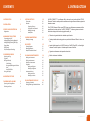
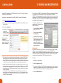
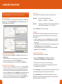
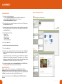
Email: [email protected] www.cordexinstruments.com Ref. ID 4000, Rev. A USER GUIDE CONTENTS 1. INTRODUCTION 1 2. INSTALLATION 2 3. PROFILE AND REGISTRATION 3 Registration 4. MANAGING YOUR UT5000 Connecting to the PC Adding/Editing/Deleting Materials Adding/Editing/Deleting RFID Tags Gauge Setup RFID Groups Get/Clear/Import Readings 5. GENERATING GRAPHS Selecting the Tag Tag Data Editing the Graph X-Axis Range Foreground/Background Colours Units Line/Bar/3D-Bar Saving the Graph 2 1. INTRODUCTION 3 4 4 4 4 5 5 5 6 6 7 7 7 7 7 7 7 6. IMPORTING PICTURES 8 7. WORKING WITH ALBUMS 9 Opening an Existing Album Deleting an Album 9 9 8. EDITING PICTURES Picture tab Data tab Cropping a Picture Copying to the Clipboard Rotating an Image Undo/Redo 10 10 10 10 10 10 10 CorDEX CONNECT™ is a software utility to be used in conjunction with the UT5000 Ultrasonic Tester to enable predictive maintenance for pipelines and fixed equipment in hazardous areas. The UT5000 Ultrasonic Tester uses RFID to tag every thickness measurement with a specific location, date and time. CorDEX CONNECT™ allows engineers and senior technicians charged with monitoring pipeline safety to: Collect and organize data into standard report formats. 9. ADDING ANNOTATIONS Rotating an Image 10. REPORTS Creating Reports Managing Reports Report Generation Wizard 11. MANAGING INSTRUMENTS Adding an Instrument Editing an Instrument Deleting an Instrument Engineers Adding an Engineer Deleting an Engineer Instrument History Adding an Action Deleting an Action 12. MAINTENANCE SCHEDULE Creating a Schedule Editing/Deleting a Scheduled Action 11 11 12 12 12 12 14 Create printable charts and graphs or export data to Microsoft Excel or into a .csv file. Import digital images from CorDEX Centurion, CorDEX ToughPIX, or other digital cameras to enrich reports or illustrate specific areas of interest. Organize maintenance and inspection schedules. Monitor instrument calibration. 14 14 14 15 15 15 15 15 15 16 16 16 Ref. ID 4000, Rev. A 1 3. PROFILE AND REGISTRATION 2. INSTALLATION Locate the CD supplied with your UT5000 and load it into your PC. Follow the on-screen instructions to install CONNECT. Alternatively, to download and install CorDEX CONNECT from the CorDEX website: 1. Go to http://connect.cordexinstruments.com 2. Register your contact details, Equipment Serial Number and License Number 1 using the online form. When you first run CONNECT, it accesses the CorDEX servers and retrieves the details you entered when you downloaded it. You will be prompted to choose whether CONNECT should use these details as the basis for your profile. If you choose not to use these details or if CONNECT fails to retrieve the information, you will be prompted to fill in the profile. Until you have provided a profile, CONNECT will prompt you to complete this step each time the program is run. Your profile is used whenever you generate a report. You can edit your profile at any time by: 3. Click on the Submit button. 4. Follow the on-screen prompts and CONNECT should automatically install onto your system.2 In the event of any difficulties, the installation process will prompt you to get help from an administrator. Choosing Profile > Create/Edit profile from the menu. Double-clicking on Profile in Your Workspace. In addition to the contact and company information, the Profile Details page also allows you to select a logo to appear on your reports. This is optional: the CONNECT logo will be displayed on reports by default. REGISTRATION Registration involves sending your details to CorDEX Instruments to enable a two-way exchange of information regarding the equipment you add to CONNECT. This information is simply notifications of calibration requirements and progress on any repairs or maintenance carried out by CorDEX Instruments. None of the data collected by the instruments will be transmitted to CorDEX Instruments at any time. 1. This is optional: if you enter a valid license number at this stage, your copy of CONNECT will be licensed during installation. Without a valid licence number, the installation will be a 30-day trial version of the software. At the end of that period you can still create reports and use all the other features. However, you will not be able to import any more images. A trial version can be converted to a full version at any time by providing a valid licence number through your profile details. 2. CONNECT uses Microsoft Framework, which is normally already present on most PCs. If it is not already installed, the setup process will install it for you automatically. This is, however, a 207MB file so it may take a while depending on your connection speed. Once installed, it will not need to be installed again for any CorDEX Instruments software or any other software from other vendors that use the Framework. By using Microsoft Framework, CONNECT can normally be installed on computers where the security settings are set to disable user installations. However, if your IT department has applied security settings for user installation and you may need to contact your administrator to carry out the Microsoft Framework installation. 2 To register: 1. Complete your profile details. 2. Select the Register check box. 3. If you want to be notified by CorDEX Instruments regarding new products, services or updates, select the adjacent check box. This will take the form of occasional emails. You can opt out of this service at any time by clearing the check box. 4. Click on the Save Data button. Ref. ID 4000, Rev. A 3 4. MANAGING YOUR UT5000 NOTE. Before you can use these features you need to register your UT5000 through the Instrument Management page (see “Adding an Instrument” on page 14). CONNECTING TO THE PC Connect your UT5000 to the PC using the supplied USB cable (see your UT5000 manual for details). Click on the Connect Equipment button on the CONNECT dashboard. The UT5000 Management page is displayed. GAUGE SETUP You can use CONNECT to change the Date Format and to set the Sleep Time. Date Format Choose from the following Date Formats: DD/MM/YYYY MM/DD/YYYY YYYY/MM/DD Sleep Timer To save power, the UT5000 will switch off after the specified period of inactivity. Choose the time period: 1, 2, 3, 4 or 5 minutes. Click on the Update button to confirm any changes. RFID GROUPS Use RFID Groups to associate tags, for example, that represent the same section of a plant or factory. Use groups to transfer RFID tag information to other devices and create schedules. To create a new group, enter its name in the New Group box. Click on the Save button to import the tag information on the currently attached device under the new group name. To merge the tags on the currently attached device with an existing group, select it in the RFID Groups list and then click on the Save button. To download tag information to the attached device, select the required RFID Group and then click on the Load button. ADDING/EDITING/DELETING MATERIALS To add a new material, type its Name, enter a Velocity (m/s) and then click on the Add/Edit button. To edit the information for an existing material, select it in the list and then change the name and velocity as required. Click on the Add/Edit button. To delete an existing material, select it in the list and click on the Delete button. ADDING/EDITING/DELETING RFID TAGS To register a new tag, type its RFID Code and enter a name in the Change RFID Alias box. Optionally, add alarm settings: enter minimum and maximum thicknesses (in microns). You can also associate a material from the Materials list (see above) and then click on the Grab button. Click on the Add/Edit button to complete the tag setup. To edit an existing tag, select its name in the RFID Alias list. Edit the alias, alarm settings and material information as required and then click on the Add/Edit button. To delete a tag, select it in the RFID Alias list and click on the Delete button. 4 GET/CLEAR/IMPORT READINGS To download all saved readings in CSV file format: 1. Click on the Download Readings button. Readings are stored in the My Documents > CorDEX Instruments > UT Gauge data files folder. 2. Choose whether you want to clear the entries from the gauge. 3. Choose whether you want the data file to be automatically opened in the PC’s default application for viewing csv files. Click on Clear Readings to delete measurements from the attached device. If you have not downloaded the readings, they cannot be restored after this action. Click on Import Readings to update CONNECT with readings from the currently attached device. Any tags in the imported readings that are not already in a defined RFID group are allocated to a 'default' group. Ref. ID 4000, Rev. A 5 5. GENERATING GRAPHS Having connected your UT5000 and downloaded RFID data and thickness measurements, you can use CONNECT to create line or bar graphs showing thickness variations at each tagged location. To display the Thickness Gauge Graph Generator, click on the RFID Data Tracking button on the dashboard. SELECTING THE TAG Select the alias of the required tag from the Location (RFID Tag) dropdown list. TAG DATA CONNECT displays the following information: First Reading - date of the first thickness reading at the tag’s location Last Reading - date of the most recent thickness reading at the tag’s location Max Reading - high thickness alarm setting Min Reading - low thickness alarm setting You can also scroll through a list of all the recorded measurements. To save the raw data for the selected tag, click on the Export Data to CSV button. EDITING THE GRAPH You can adjust various features of the displayed graph: X-Axis Range By default, CONNECT shows all the recorded data. You can adjust the displayed range by changing the Start Date and End Date values. Click on the Update Graph button to apply the new settings. Foreground/Background Colours The foreground consists of the lines/bars and X-axis ticks and labels; the background is the graph area. CONNECT’s default palette uses a black foreground with an off-white background. Use the Foreground Colour and Background Colour list boxes to choose from: Orange, White, Off White, Pale Blue, Pale Green, Beige, Pale Grey, Dark Grey, Navy Blue, Dark Green or Black. Changes to the colour palette are applied automatically. Note. The Max/Min alarm settings and graph annotations are displayed in red and axis labels and notes in black. These colours cannot be changed. Units Use the Units list box to choose whether CONNECT displays thickness measurements in millimetres or inches. Line/Bar/3D Bar Use the option buttons to change the type of graph you want to display. SAVING THE GRAPH Click on the Save Graph button to store it as an image in one of CONNECT’s image libraries. Choose an existing library or type a name for a new library. You can edit the image and add annotations (see page 11) and use it in reports (see page 12). 6 Ref. ID 4000, Rev. A 7 6. IMPORTING PICTURES To import new images into a CONNECT album: 1. Choose one of the following options: Click on the Image Management button on the CONNECT dashboard, or Choose File > Load/Import from the main menu, or Open the Images folder in Your Workspace and double-click on Albums. The Select Album dialog box is displayed. 7. WORKING WITH ALBUMS OPENING AN EXISTING ALBUM To view images in an existing CONNECT album, open the Images folder in Your Workspace and either double-click on the album's name or right click on it and select Open from the context menu. Alternatively, choose one of the following options: Click on the Image Management button on the CONNECT dashboard, or Choose File > Load/Import from the main menu Then, in the Select Album dialog box, choose the required album from the Existing Albums dropdown list. Album images are displayed as thumbnails for reviewing purposes. Use the toolbar buttons1 to view, edit or export images: 2. Click on the Import Pictures button. 3. If you want to add the pictures to an existing album, select it from the Existing Albums dropdown list. Otherwise, enter the name of the new album in the New Album Name text box. Return to the main menu Open the image for viewing Copy the image to the clipboard Edit the image, add annotations, etc Export the image Delete the image Save image View/edit previous image View/edit next image View/edit your equipment View/edit your profile View the open album 4. Choose from the following options: Delete Original Images Import in Report Mode Add Date Stamp to Images 5. Click on the Select Pictures button. Using the standard Windows Open dialog box, choose the pictures you want to import either directly from the camera or from a folder on your computer. 6. Click on the Open button to continue. It may take a while to import your images. When this process is complete, the album is displayed. DELETING AN EXISTING ALBUM To delete an existing CONNECT album, open the Images folder in Your Workspace, right click on the album's name and select Delete from the context menu. Confirm that you want to delete the album. 1. These functions (and the Zoom function) are also available by right-clicking on an image and selecting the appropriate command from the context menu. 8 Ref. ID 4000, Rev. A 9 8. EDITING PICTURES To edit an album picture, click on the button or, alternatively, right click on the image and select Edit from the context menu. 9. ADDING ANNOTATIONS To add an annotation to the image: 1. Choose the color and thickness of the lines for the annotation marker using the drop down boxes in the top right corner of the window. The editing window provides a number of tools to make changes and add information to the picture. PICTURE TAB 2. Choose whether you want to use a circle, square, polygon or line as the marker. Use the Picture tab to: Change the color pallette Adjust the image's brightness and contrast Change the size and/or aspect ratio of the image Add text annotations (see the next section) For all except the polygon, click on the picture and then drag the mouse, holding down the left mouse button. CONNECT adds the relevant shape to the picture. For a polygon, click on the picture normally, then move the mouse without holding the mouse down and click again. Repeat this procedure to complete the required outline, then either click on the start point again or double click to complete the polygon. Each shape you add is given an associated Marker ID number. DATA TAB Use the Data tab to change the metadata associated with the image: Name Date Location Primary and Secondary Assigned Device Notes - a description of the picture Importance settings Cropping a Picture Starting at one corner, hold down the left mouse button and drag a rectangle over the part of the image that you want to keep. Release the mouse and click OK. Copy to the Clipboard Click and drag a square to cover the area you want to copy. Release the mouse button and click on the Yes button to confirm. Rotate the Image Rotate the picture 90° clockwise or anticlockwise. 3. On the Picture tab, select the annotation marker using the Select a Marker ID dropdown list. 4. In the text box below, add the annotation text to be associated with this marker and and rate its importance. This text will be used on the compiled report; only the marker and its ID number appear on the image. 5. Assign a priority rating to the annotation: High Importance, Advisory or Information Only. 6. Use the Data tab to enter additional information. You can place annotations on different layers that can be hidden, deleted and reordered using the Layers panel on the right side of the window. Use the Zoom and scroll bars to frame the image and annotations. Undo/Redo Undo the last action/re-apply the last undone action 10 Ref. ID 4000, Rev. A 11 10. REPORTS CREATING REPORTS REPORT GENERATION WIZARD 1. Choose one of the following options: Click on the Report Creation button on the CONNECT dashboard, or Choose Report > Report Creation from the main menu, or The Report Generation Wizard is displayed. Step 1 Choose the images and enter report details 2. Choose the Album which contains the images you want to use for this Report using the Select Album dropdown list. 3. Select the images to be included by selecting or clearing the check box associated with each image thumbnail. If you want to include all the images in the album, click on the Select All button. Step 2 Choose format 4. Enter the following information: Report Title Report Subtitle Report Summary Client Company Client Contact Details 5. Click on the Next button. 6. Select the required report format from those shown. 7. Click on the Next button. Step 3 Preview Report 8. Preview the report, changing the text information if necessary. Click on the Refresh button if you make any changes. If you want to use different images, click on the Back button. If you want to edit an image or its annotations, return to CONNECT and complete the modifications in the image editor (see pages 6&7). Remember to click on the Save button when you have finished. Then, back in the Report Generation Wizard, click on the Refresh button to update the draft report with the new images. 9. If the report is acceptable, click on the Generate Report button. CONNECT saves the report, generates a PDF version and opens it for viewing. MANAGING REPORTS To open, rename or delete an existing report, open the Reports folder in Your Workspace. Reports are stored in nested yearly and monthly folders. Right click on a report and choose the required option from the displayed context menu: Open, Rename or Delete. You can also open a report by double-clicking on its name. On your computer, reports are stored in My Documents > CorDEX Instruments > Reports. 12 Ref. ID 4000, Rev. A 13 11. MANAGING INSTRUMENTS To manage the instruments registered with CONNECT choose one of the following options: Click on the Instrument Management button on the CONNECT dashboard, or Choose View > Instrument Management from the main menu, or Double-click on the Instruments folder in Your Workspace The Enter or edit the details for your instruments dialog box is displayed. You may add your own comments in the Notes text box. The Instrument History can be used to record particular events of note such as a change of ownership or return for repair or recalibration. This history also lists events entered by CorDEX Instruments. For example, if a product is sent back to the factory for recalibration then the receipt, the recalibration, and the return will all appear in the history allowing you to track the progress of the recalibration. Your own reported actions can be added and deleted but any actions entered by the CorDEX Instruments factory are permanent. Remember to click on the Save Data button when you have finished. ADDING AN INSTRUMENT For a CorDEX Instruments product, type in the Instrument S/N for the instrument (you will find this on the Certification Plate that is on the instrument in the form 0000-0000 or 000000-000000.) Assuming you are connected to the internet as you do this, CONNECT will recognise the form of the Serial Number and contact the CorDEX Instruments server to get the details for the product and automatically input them for you. For other instruments, enter the Instrument S/N and Model manually. Optionally, enter the name of the owner/user of the instrument. EDITING AN INSTRUMENT To edit an instrument, select it from the Select Instrument dropdown list. Edit the details as required and then click on the Save Data button. DELETING AN INSTRUMENT To delete an instrument, select it from the Select Instrument dropdown list. Then, click on the Delete button. ENGINEERS Use the Engineers section to list the names of operators authorised to carry out scheduled maintenance or inspections using the selected instrument. Adding an Engineer To register an engineer, type their name into the text box above the Add/Delete buttons, then click on the Add button. Deleting an Engineer To delete an engineer, select it in the action list, then click on the Delete button. INSTRUMENT HISTORY The Instrument History section lists the actions associated with the selected instrument. An action could be routine maintenance, calibration or use in a specific set of measurements. Maintenance-related actions may be added to the list automatically by CorDEX Instruments. Adding an Action To add an action, type its details into the text box under the Instrument History heading, then click on the Add Action button. Deleting an Action To delete an action, select it in the action list. Then, click on the Delete button. 14 Ref. ID 4000, Rev. A 15 12. MAINTENANCE SCHEDULING CREATING A SCHEDULE 1. To create a scheduled inspection, choose one of the following options: Click on the Maintenance Schedule button on the CONNECT dashboard, or Choose View > Maintenance Schedule from the main menu The Maintenance Scheduling page is displayed. 2. In the Date Selection calendar, select the first day for the scheduled event by clicking on it. Use the arrowed keys at the top of the calendar to browse to other months. The Scheduled Maintenance box will list any existing inspections or actions created for the selected day. 3. In the RFID Management box, select the RFID tag to be inspected by choosing its RFID Group from the RFID List. Then, select the tag’s name from the RFID Alias list. Data from previous inspections is listed: the dates of the first and last readings and the maximum and minimum alarm settings. Click on the View Data button to launch the Graph Generator (see page 6). Click on the Export Data button to save the data in a CSV file. If you want to edit the selected RFID group, click on the Edit List button. You can then use the Action Pane to delete selected tags from the group. 4. To add a scheduled action for the selected RFID Tag, click on the Add Schedule button in the RFID Management box. 5. In the Action Pane: Choose the Type of inspection: Visual, UT Scan or Other. Use the Add Comment box below to add any explantory text. Use the Every box to set the frequency of the inspection: Day, Week, Month, 2 Months, 3 Months, 4 Months, Months, 6 Months, 8 Months, 10 Months, Year, 18 Months, 2 Years. Ensure that the Weekdays Only check box is selected if the inspections are not to be scheduled at weekends. Check the date of the First Inspection. This is set to the date you selected in the Data Selection calendar. If this is incorrect, either select the correct date in the calendar or type the date directly into the box. Identify the Engineer with responsibility for the inspection. In CONNECT, engineers are registered on the Instrument Management page (see page 14). 6. Click on the Add Schedule button. The new action is added to CONNECT’s scheduled maintenance list. 16 EDITING/DELETING A SCHEDULED ACTION To edit or delete a scheduled action: 1. Click on a day in the Date Selection calendar when the event is scheduled. It is then listed in the Scheduled Maintenance box. 2. Click on the event’s Edit button. Its details are listed in the Action Pane. 3. Edit or delete the action as required: To edit the schedule, follow the steps described in the previous section. Click on the Edit Schedule button to finish. To delete the action, click on the Delete Schedule button and confirm the action. Ref. ID 4000, Rev. A 17 distributed by UK Headquarters: Cordex Instruments Ltd Unit 1 Owens Road Skippers Lane Industrial Estate Middlesbrough Cleveland TS6 6HE Copyright © 2011, CorDEX Instruments Limited. All other brand and product names are trademarks of CorDEX Instruments Limited. Ref. ID 4000, Rev. A