1
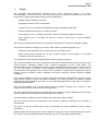
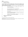
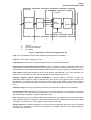
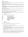
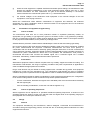
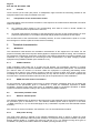
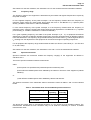
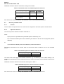
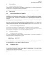
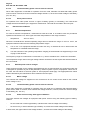
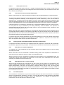
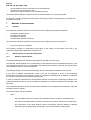
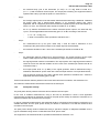
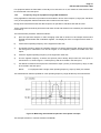
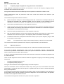
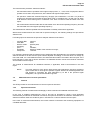
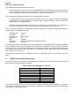
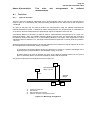
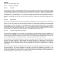
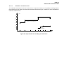
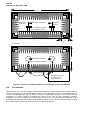
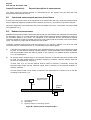
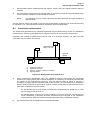
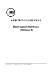
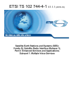
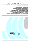
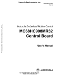
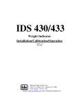
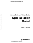
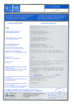
EUROPEAN
TELECOMMUNICATION
STANDARD
ETS 300 328
November 1996
Second Edition
Source: ETSI TC-RES
Reference: RE/RES-10-09
ICS: 33.060.20 33.060.50
Key words: Data, emission, mobile, radio, spread spectrum, testing, transmission
Radio Equipment and Systems (RES);
Wideband transmission systems;
Technical characteristics and test conditions for
data transmission equipment operating in the 2,4 GHz ISM band
and using spread spectrum modulation techniques
ETSI
European Telecommunications Standards Institute
ETSI Secretariat
Postal address: F-06921 Sophia Antipolis CEDEX - FRANCE
Office address: 650 Route des Lucioles - Sophia Antipolis - Valbonne - FRANCE
X.400: c=fr, a=atlas, p=etsi, s=secretariat - Internet: [email protected]
Tel.: +33 4 92 94 42 00 - Fax: +33 4 93 65 47 16
Copyright Notification: No part may be reproduced except as authorized by written permission. The copyright and the
foregoing restriction extend to reproduction in all media.
© European Telecommunications Standards Institute 1996. All rights reserved.
Page 2
ETS 300 328: November 1996
Whilst every care has been taken in the preparation and publication of this document, errors in content,
typographical or otherwise, may occur. If you have comments concerning its accuracy, please write to
"ETSI Editing and Committee Support Dept." at the address shown on the title page.
Page 3
ETS 300 328: November 1996
Contents
Foreword .......................................................................................................................................................5
Introduction....................................................................................................................................................5
1
Scope ..................................................................................................................................................7
2
Normative references..........................................................................................................................8
3
Definitions and abbreviations ..............................................................................................................8
3.1
Definitions ............................................................................................................................8
3.2
Abbreviations .....................................................................................................................10
4
General..............................................................................................................................................10
4.1
Manufacturer declarations .................................................................................................10
4.2
Presentation of equipment for type testing ........................................................................11
4.2.1
Choice of model ............................................................................................11
4.2.2
Presentation ..................................................................................................11
4.2.3
Choice of operating frequencies....................................................................11
4.3
Design................................................................................................................................11
4.3.1
General..........................................................................................................11
4.3.2
Controls .........................................................................................................12
4.4
Interpretation of the measurement results.........................................................................12
5
Technical characteristics...................................................................................................................12
5.1
Modulation .........................................................................................................................12
5.1.1
FHSS modulation ..........................................................................................12
5.1.2
DSSS and other forms of modulation............................................................12
5.2
Transmitter parameter limits..............................................................................................12
5.2.1
Effective radiated power................................................................................12
5.2.2
Peak power density .......................................................................................12
5.2.3
Frequency range ...........................................................................................13
5.2.4
Spurious emissions .......................................................................................13
5.3
Receiver parameter limits ..................................................................................................14
5.3.1
General..........................................................................................................14
5.3.2
Spurious emissions .......................................................................................14
6
Test conditions ..................................................................................................................................15
6.1
Normal and extreme test conditions ..................................................................................15
6.2
Power sources ...................................................................................................................15
6.2.1
Power sources for stand-alone equipment....................................................15
6.2.2
Power sources for plug-in radio devices .......................................................15
6.3
Normal test conditions .......................................................................................................15
6.3.1
Normal temperature and humidity .................................................................15
6.3.2
Normal power source ....................................................................................15
6.3.2.1
Mains voltage.......................................................................15
6.3.2.2
Lead-acid battery power sources used on vehicles.............16
6.3.2.3
Other power sources ...........................................................16
6.4
Extreme test conditions .....................................................................................................16
6.4.1
Extreme temperatures...................................................................................16
6.4.2
Extreme power source voltages ....................................................................16
6.4.2.1
Mains voltage.......................................................................16
6.4.2.2
Lead-acid battery power sources used on vehicles.............16
6.4.2.3
Power sources using other types of batteries......................16
6.4.2.4
Other power sources ...........................................................17
6.4.3
Procedure for tests at extreme temperatures ...............................................17
6.5
Testing of host connected equipment and plug-in radio devices.......................................17
6.5.1
Alternative A: combined equipment...............................................................17
Page 4
ETS 300 328: November 1996
6.6
6.5.2
Alternative B: use of a host or test jig ........................................................... 17
Test data sequence........................................................................................................... 17
7
Methods of measurement................................................................................................................. 18
7.1
General.............................................................................................................................. 18
7.2
Measurements of transmitter parameters ......................................................................... 18
7.2.1
Effective radiated power ............................................................................... 18
7.2.2
Peak power density....................................................................................... 19
7.2.3
Frequency range of equipment using FHSS modulation .............................. 21
7.2.4
Frequency range of equipment using other forms of modulation ................. 22
7.2.5
Spurious emissions....................................................................................... 22
7.3
Measurements of receiver parameters ............................................................................. 23
7.3.1
General ......................................................................................................... 23
7.3.2
Spurious emissions....................................................................................... 23
8
Measurement uncertainty values...................................................................................................... 24
Annex A (normative):
Test sites and arrangements for radiated measurements................................. 25
A.1
Test sites .......................................................................................................................................... 25
A.1.1
Open air test sites ............................................................................................................. 25
A.1.2
Anechoic chamber ............................................................................................................ 26
A.1.2.1
General ......................................................................................................... 26
A.1.2.2
Description.................................................................................................... 26
A.1.2.3
Influence of parasitic reflections ................................................................... 26
A.1.2.4
Calibration and mode of use......................................................................... 27
A.2
Test antenna..................................................................................................................................... 28
A.3
Substitution antenna ......................................................................................................................... 29
Annex B (normative):
General description of measurement ................................................................ 30
B.1
Conducted measurements and use of test fixture............................................................................ 30
B.2
Radiated measurements .................................................................................................................. 30
B.3
Substitution measurement................................................................................................................ 31
Annex C (informative):
Bibliography ....................................................................................................... 32
History ......................................................................................................................................................... 33
Page 5
ETS 300 328: November 1996
Foreword
This European Telecommunication Standard (ETS) has been produced by the Radio Equipment and
Systems (RES) Technical Committee of the European Telecommunications Standards Institute (ETSI).
Annex A provides additional requirements concerning radiated measurements.
Annex B contains normative specifications for the adjustment of the measurement equipment and of the
equipment to be measured in order to achieve correct results.
Annex C provides a Bibliography.
Transposition dates
Date of adoption of this ETS:
8 November 1996
Date of latest announcement of this ETS (doa):
28 February 1997
Date of latest publication of new National Standard
or endorsement of this ETS (dop/e):
31 August 1997
Date of withdrawal of any conflicting National Standard (dow):
31 August 1997
Introduction
Wideband radio data transmission systems are rapidly being introduced into a variety of commercial and
industrial applications and the technology employed by these systems is still developing.
This ETS may be used by accredited test laboratories for the assessment of the performance of the
equipment. The performance of the equipment submitted for type testing should be representative for the
performance of the corresponding production model. In order to avoid any ambiguity in that assessment,
this ETS contains instructions for the presentation of equipment for type testing purposes (clause 4),
testing conditions (clause 6) and methods of measurement (clause 7).
This ETS assumes that:
-
the type test measurements performed in an accredited test laboratory in one CEPT country would
be accepted by the Type Approval Authority in another country provided that the national regulatory
requirements are met (see CEPT Recommendation T/R 71-03 [3]);
-
if equipment available on the market is required to be checked it would be tested in accordance with
the methods of measurement specified in this ETS.
Page 6
ETS 300 328: November 1996
Blank page
Page 7
ETS 300 328: November 1996
1
Scope
This European Telecommunication Standard (ETS) covers equipment referred to in CEPT
Recommendation T/R 10-01 [1]. This ETS covers the minimum technical characteristics for radio data
transmission equipment having the following technical parameters:
-
wideband radio modulation techniques;
-
aggregate bit rates in excess of 250 kbits/s;
-
operation in the 2,4 to 2,483 5 GHz Industrial, Scientific and Medical (ISM) band;
-
effective radiated power of up to -10 dBW (100 mW);
-
power density of up to -10 dBW (100 mW) per 100 kHz for frequency hopping modulation;
-
power density of up to -20 dBW (10 mW) per 1 MHz for other forms of spread spectrum
modulation.
This ETS only addresses the transceivers, transmitters and receivers of equipment offered for testing.
The equipment offered for testing may be used in fixed, mobile or portable applications, e.g.:
-
stand-alone radio equipment with or without their own control provisions;
-
plug-in radio devices intended for use with or within a variety of host systems, e.g. personal
computers, hand-held terminals, etc.
The equipment may be fitted with integral antennae and/or antenna connectors.
CEPT Recommendation T/R 10-01 [1] defines the total power and power density limits for systems using
spread spectrum modulation together with a minimum aggregate bit rate of 250 kbits/s. The
Recommendation does not address the details of these modulation techniques. Therefore, this ETS does
not cover the design or operation of the equipment being tested but describes a common set of
measurements to be applied to various types of such equipment, including those employing Frequency
Hopping Spread Spectrum (FHSS) modulation and Direct Sequence Spread Spectrum (DSSS)
modulation.
CEPT Recommendation T/R 10-01 [1] specifies that spread spectrum modulation be used and it gives
power density values for FHSS and DSSS modulation. This ETS specifies the minimum technical
parameters of FHSS modulation such that it can be clearly differentiated from other types of modulation,
including DSSS modulation.
CEPT Recommendation T/R 01-04 [2] defines limits of spurious emissions for a variety of radio
equipment; these limits are used in this ETS as appropriate.
This ETS describes measurements for operating frequency range(s), effective radiated power and power
density as well as spurious emissions for transmitters and receivers.
The measurement methods have been adapted from ETR 027 [4] where possible.
This ETS specifies test site characteristics, test conditions, equipment calibration and methods of
measurement.
This ETS is a general standard which may be superseded by specific standards covering specific
applications.
Additional standards or specifications may be required for equipment such as that intended for connection
to the Public Switched Telephone Network (PSTN) and/or other Public Data Networks (PDN).
Page 8
ETS 300 328: November 1996
2
Normative references
This ETS incorporates by dated and undated reference, provisions from other publications. These
normative references are cited at the appropriate places in the text and the publications are listed
hereafter. For dated references, subsequent amendments to or revisions of any of these publications
apply to this ETS only when incorporated in it by amendment or revision. For undated references the latest
edition of the publication referred to applies.
[1]
CEPT Recommendation T/R 10-01: "Wideband Data Transmission in the
2,4 GHz to 2,5 GHz ISM band".
[2]
CEPT Recommendation T/R 01-04: "Low Power Devices".
[3]
CEPT Recommendation T/R 71-03: "Procedures for Type Testing and Approval
for Radio Equipment intended for non-public systems".
[4]
ETR 027: "Radio Equipment and Systems; Methods of measurement for mobile
radio equipment".
[5]
ETR 028: "Radio Equipment and Systems; Uncertainties in the measurement of
mobile radio equipment characteristics".
[6]
EN 55022: "Limits and methods of measurement of radio disturbance
characteristics of information technology equipment".
3
3.1
Definitions and abbreviations
Definitions
For the purposes of this ETS, the following definitions apply:
aggregate bit rate: The bit rate at the air interface (see point D in figure 1) including protocol overhead
where applicable and excluding the effects of signal spreading.
Page 9
ETS 300 328: November 1996
radio device
transmitter
data 1
clock 1
Data buffer
processing
signal
spreading
data n
clock n
Tx
amplifier
spreading signal
A
A:
B:
C:
D:
B
C
D
Interface
Input into processing logic
Input into the modulator
Air Interface
Figure 1: Parameters related to the aggregate bit rate
chip: A unit of modulation used in direct sequence spread spectrum modulation.
chip rate: The number of chips per second.
chip sequence: A sequence of chips with defined length and defined chip polarities.
direct sequence spread spectrum modulation: A form of modulation where a combination of data to be
transmitted and a known code sequence (chip sequence) is used to directly modulate a carrier, e.g. by
phase shift keying. The transmitted bandwidth is determined by the chip rate and the modulation scheme.
fixed station: Equipment intended for use in a fixed location and fitted with one or more antennae. The
equipment may be fitted with either antenna socket(s) or integral antenna(e) or both.
frequency hopping spread spectrum modulation: A spread spectrum technique in which the
transmitter signal occupies a number of frequencies in time, each for some period of time, referred to as
the dwell time. Transmitter and receiver follow the same frequency hop pattern. The frequency range is
determined by the lowest and highest hop positions and the bandwidth per hop position (see subclause
5.2.3).
frequency range: The range of operating frequencies over which the equipment can be adjusted.
hand-portable station: Equipment normally used on a stand-alone basis and to be carried by a person or
held in the hand. The equipment may be fitted with one or more antennae. The equipment may be fitted
with either antenna socket(s) or integral antenna(e) or both.
host: Host equipment is any equipment which has complete user functionality when not connected to the
radio equipment part and to which the radio equipment part provides additional functionality and to which
connection is necessary for the radio equipment part to offer functionality.
integral antenna: An antenna designed to be connected to the equipment without the use of a standard
connector and considered to be part of the equipment. An integral antenna may be fitted internally or
externally to the equipment.
Page 10
ETS 300 328: November 1996
manufacturer: For the purposes of this ETS "manufacturer" is understood to refer to the manufacturer or
applicant of equipment offered for testing.
mobile station: Equipment normally used in a vehicle or as a transportable station. The equipment may
be fitted with one or more antennae. The equipment may be fitted with either antenna socket(s) or integral
antenna(e) or both.
operating frequency: The nominal frequency at which the equipment can be operated; this is also
referred to as the operating centre frequency. Equipment may be adjustable for operation at more than
one operating frequency.
plug-in radio device: Equipment intended to be used with or within variety of host systems, using their
control functions and power supply.
power envelope: The frequency/power contour within which the useful RF power is generated.
spread spectrum modulation: A modulation technique in which the energy of a transmitted signal is
spread throughout a relatively large portion of the frequency spectrum.
stand-alone radio equipment: Equipment that is intended primarily as communications equipment and
that is normally used on a stand-alone basis.
3.2
Abbreviations
For the purposes of this ETS, the following abbreviations apply:
dBW
dBm
DSSS
e.i.r.p.
FHSS
ISM
ITE
RF
Rx
Tx
4
4.1
dB relative to 1 watt power
dB relative to 1 milliwatt power
Direct Sequence Spread Spectrum
equivalent isotropically radiated power
Frequency Hopping Spread Spectrum
Industrial, Scientific and Medical
Information Technology Equipment
Radio Frequency
Receiver
Transmitter
General
Manufacturer declarations
The manufacturer shall declare the following specific characteristics of the equipment:
a)
the aggregate bit rate (see subclause 3.1 for the definition);
b)
the type of modulation used: FHSS modulation, DSSS modulation or any other type of spread
spectrum modulation (see subclause 5.1);
c)
where FHSS modulation is used: the number of hopping channels, the dwell time per channel and
the maximum time between two instances of use of the same channel; these values shall fall within
the specifications given in subclause 5.1.1;
d)
the operating frequency range(s) of the equipment and, where applicable, band(s) of operation (see
subclause 5.2.3);
e)
the type of the equipment, for example: stand-alone equipment or plug-in radio devices (see also
subclause 3.1). In case of combined equipment using a plug-in radio device, and more than one
combination is intended, each combination should be declared as well (see also subclause 6.5.1);
f)
the extreme operating conditions that apply to the equipment offered for testing;
Page 11
ETS 300 328: November 1996
g)
where the radio equipment is capable of different transmitter power settings, the manufacturer shall
declare the intended combination(s) of the radio equipment power settings and one or more
antenna assemblies. For each combination, the gain of the antenna assembly i.e. the transfer
function between the conducted RF power and e.i.r.p., shall be declared;
h)
the nominal voltages of the stand-alone radio equipment or the nominal voltages of the host
equipment in case of plug-in devices.
Where the manufacturer offers different combinations of equipment and antennae, the antennae
appropriate for a given combination shall be referenced either on the equipment and on the antennae
and/or in the user documentation.
4.2
4.2.1
Presentation of equipment for type testing
Choice of model
The manufacturer shall offer one or more production models or equivalent preliminary models, as
appropriate, for type testing. If type approval is given on the basis of tests on (a) preliminary model(s),
then the corresponding production models shall be identical to the tested models in all respects relevant
for the purposes of this standard, to the preliminary model(s) tested.
Software fitted to production models shall be substantially the same as that used during type testing.
Due to the low levels of RF signal and the wideband modulations used in this type of equipment, radiated
RF power measurements are imprecise. Conducted measurements are much more precise; in
combination with the declared antenna assembly gain(s) adequate assurance of the RF characteristics
can be achieved. Therefore, equipment offered for testing shall preferably provide a suitable connector for
conducted RF power measurements. Where this is not possible, the manufacturer shall provide a
documented test fixture that converts the radiated signal into a conducted signal into a suitable
termination. Alternatively, radiated measurements shall be performed.
4.2.2
Presentation
Stand-alone equipment shall be offered complete with any ancillary equipment needed for testing. The
manufacturer shall declare, the range of operating conditions and power requirements as applicable in
order to establish the appropriate test conditions.
Plug-in radio devices may be offered for testing together with a suitable test jig and/or host equipment
intended for normal use (see subclause 6.5). The manufacturer shall declare the range of operating
conditions and power requirements that are applicable in order to establish the appropriate test conditions.
Where a manufacturer declares multiple combinations of radio equipment and antennae, the configuration
to be used for testing shall be chosen as follows except where specified otherwise:
-
for each combination, determine the highest user selectable power level and the antenna assembly
with the highest gain;
-
from the resulting combinations, choose the one with the highest e.i.r.p.
4.2.3
Choice of operating frequencies
Where equipment can be adjusted to or operated at different operating frequencies, a minimum of two
operating frequencies shall be chosen such that the lower and higher limits of the operating range(s) of
the equipment are covered (see subclause 5.2.3).
4.3
4.3.1
Design
General
The equipment submitted by the manufacturer, shall be designed, constructed and manufactured in
accordance with good engineering practice, and with the aim of minimizing harmful interference to other
equipment and services.
Page 12
ETS 300 328: November 1996
4.3.2
Controls
Those controls (of the radio part) which, if maladjusted, might increase the interfering potential of the
equipment shall not be easily accessible to the user.
4.4
Interpretation of the measurement results
The interpretation of the test results recorded in a test report for the measurements described in this ETS
shall be as follows:
a)
the measured value related to the corresponding limit shall be used to decide whether an
equipment meets the requirements of the ETS;
b)
the actual measurement uncertainty of the test laboratory carrying out the measurements, for each
particular measurement, in accordance with ETR 028 [5], shall be recorded in the test report.
The recorded value of the measurement uncertainty shall be, for each measurement, equal to or lower
than the figures in clause 8 (table of measurement uncertainty).
5
5.1
Technical characteristics
Modulation
The manufacturer shall declare the modulation characteristics of the equipment to be tested. For the
purpose of deciding which level of power density applies to equipment offered for testing, this ETS defines
two categories of equipment: equipment conforming to the stated characteristics of FHSS modulation (see
subclause 5.1.1) and equipment not conforming to these characteristics. The latter category includes
equipment using DSSS modulation (see subclause 5.1.2).
5.1.1
FHSS modulation
FHSS modulation shall make use of at least 20 well defined, non-overlapping channels or hopping
positions separated by the channel bandwidth as measured at 20 dB below peak power. The dwell time
per channel shall not exceed 0,4 seconds. While the equipment is operating (transmitting and/or
receiving) each channel of the hopping sequence shall be occupied at least once during a period not
exceeding four times the product of the dwell time per hop and the number of channels. Systems that
meet the above constraints shall be tested according to the requirements for FHSS modulation.
5.1.2
DSSS and other forms of modulation
For the purposes of this standard, other forms of spread spectrum modulation which do not satisfy the
constraints of the specification given in subclause 5.1.1, shall be considered equivalent to DSSS
modulation. Systems using these other forms of modulation shall be considered equivalent to DSSS
systems and shall be tested according to the requirements for DSSS modulation.
5.2
5.2.1
Transmitter parameter limits
Effective radiated power
The effective radiated power is defined as the total power of the transmitter and is calculated according to
the procedure given in subclause 7.2.1. The effective radiated power shall be equal to or less than
-10 dBW (100 mW) e.i.r.p. This limit shall apply for any combination of power level and intended antenna
assembly.
See clause 6 for the test conditions; see subclause 7.2.1 for the measurement method.
5.2.2
Peak power density
The peak power density is defined as the highest instantaneous level of power in Watts per Hertz
generated by the transmitter within the power envelope. For equipment using FHSS modulation, the power
density shall be limited to -10 dBW (100 mW) per 100 kHz e.i.r.p. For equipment using other types of
modulation, the peak power shall be limited to -20 dBW (10 mW) per MHz e.i.r.p.
Page 13
ETS 300 328: November 1996
See clause 6 for the test conditions; see subclause 7.2.2 for the measurement and calculation methods.
5.2.3
Frequency range
The frequency range of the equipment is determined by the lowest and highest frequencies occupied by
the power envelope.
fH is the highest frequency of the power envelope: it is the frequency furthest above the frequency of
maximum power where the output power drops below the level of -80 dBm/Hz e.i.r.p. spectral power
density (-30 dBm if measured in a 100 kHz bandwidth).
fL is the lowest frequency of the power envelope; it is the frequency furthest below the frequency of
maximum power where the output power drops below the level equivalent to -80 dBm/Hz e.i.r.p. spectral
power density (or -30 dBm if measured in a 100 kHz bandwidth).
For a given operating frequency, the width of the power envelope is (fH - fL). In equipment that allows
adjustment or selection of different operating frequencies, the power envelope takes up different positions
in the allocated band. The frequency range is determined by the lowest value of fL and the highest value of
fH resulting from the adjustment of the equipment to the lowest and highest operating frequencies.
For all equipment the frequency range shall lie within the band 2,4 GHz to 2,483 5 GHz (fL > 2,4 GHz and
fH <2,483 5 GHz).
See clause 6 for the test conditions; see subclauses 7.2.3 and 7.2.4 for the measurement methods.
5.2.4
Spurious emissions
Spurious emissions are emissions outside the frequency range(s) of the equipment as defined in
subclause 5.2.3.
The level of spurious emissions shall be measured as:
either:
a) their power in a specified load (conducted spurious emissions); and
b) their effective radiated power when radiated by the cabinet or structure of the equipment (cabinet
radiation);
or:
c) their effective radiated power when radiated by cabinet and antenna.
The spurious emissions of the transmitter shall not exceed the values in tables 1 and 2 in the indicated
bands.
Table 1: Transmitter limits for narrowband spurious emissions
Frequency Range
30 MHz - 1 GHz
above 1 GHz - 12,75 GHz
1,8 - 1,9 GHz
5,15 - 5,3 GHz
Limit when
operating
- 36 dBm
Limit when
in standby
- 57 dBm
- 30 dBm
- 47 dBm
- 47 dBm
- 47 dBm
The above limit values apply to narrowband emissions, e.g. as caused by local oscillator leakage. The
measurement bandwidth for such emissions may be as small as necessary to achieve a reliable
measurement result.
Page 14
ETS 300 328: November 1996
Wideband emissions shall not exceed the values given in table 2.
Table 2: Transmitter limits for wideband spurious emissions
Frequency Range
30 MHz - 1 GHz
above 1 GHz - 12,75 GHz
1,8 - 1,9 GHz
5,15 - 5,3 GHz
Limit when Limit when in
operating
standby
- 86 dBm/Hz - 107 dBm/Hz
- 80 dBm/Hz - 97 dBm/Hz
- 97 dBm/Hz - 97 dBm/Hz
See clause 6 for the test conditions; see subclause 7.2.5 for the measurement methods.
5.3
5.3.1
Receiver parameter limits
General
This ETS does not impose limits on the receiver of the equipment other than spurious emission limits.
5.3.2
Spurious emissions
The level of spurious emissions shall be measured as:
either:
a) their power in a specified load (conducted spurious emissions); and
b) their effective radiated power when radiated by the cabinet or structure of the equipment (cabinet
radiation);
or:
c) their effective radiated power when radiated by cabinet and antenna.
The spurious emissions of the receiver shall not exceed the values in tables 3 and 4 in the indicated
bands.
Table 3: Narrowband spurious emission limits for receivers
Frequency Range
30 MHz - 1 GHz
above 1 GHz - 12,75 GHz
Limit
- 57 dBm
- 47 dBm
The above limit values apply to narrowband emissions, e.g. as caused by local oscillator leakage. The
measurement bandwidth for such emissions may be as small as necessary to get a reliable measurement
result.
Wideband emissions shall be not exceed the values given in table 4.
Table 4: Wideband spurious emission limits for receivers
Frequency Range
30 MHz - 1 GHz
above 1 GHz - 12,75 GHz
Limit
- 107 dBm/Hz
- 97 dBm/Hz
See clause 6 for the test conditions; see subclause 7.3 for the measurement methods.
Page 15
ETS 300 328: November 1996
6
Test conditions
6.1
Normal and extreme test conditions
Type tests shall be made under normal test conditions and where stated in the methods of measurement
(see also clause 7), under extreme conditions (subclause 6.4.1).
Exceptions to the measurement procedures given in this clause shall be recorded in the test report.
6.2
Power sources
6.2.1
Power sources for stand-alone equipment
During type tests, the power source of the equipment shall be replaced by a test power source capable of
producing normal and extreme test voltages as specified in subclauses 6.3.2 and 6.4.2. The internal
impedance of the test power source shall be low enough for its effect on the test results to be negligible.
For the purpose of tests, the voltage of the power source shall be measured at the input terminals of the
equipment.
For battery operated equipment the battery shall be removed and the test power source shall be applied
as close to the battery terminals as practicable.
During tests the power source voltages shall be maintained within a tolerance of ± 1 % relative to the
voltage at the beginning of each test. The value of this tolerance is critical to power measurements; using
a smaller tolerance will provide better measurement uncertainty values.
6.2.2
Power sources for plug-in radio devices
The power source for testing plug-in radio devices shall be provided by a test jig or host equipment.
Where the host equipment and/or the plug-in radio device is battery powered, the battery may be removed
and the test power source applied as close to the battery terminals as practicable.
6.3
Normal test conditions
6.3.1
Normal temperature and humidity
The normal temperature and humidity conditions for tests shall be any convenient combination of
temperature and humidity within the following ranges:
-
temperature:
-
relative humidity:
+15°C to +35°C;
20 % to 75 %.
When it is impracticable to carry out the tests under these conditions, a note to this effect, stating the
ambient temperature and relative humidity during the tests, shall be recorded in the test report.
The actual values during the tests shall be recorded in the test report.
6.3.2
6.3.2.1
Normal power source
Mains voltage
The normal test voltage for equipment to be connected to the mains shall be the nominal mains voltage.
For the purpose of this ETS, the nominal voltage shall be the declared voltage or any of the declared
voltages for which the equipment was designed.
The frequency of the test power source corresponding to the AC mains shall be between 49 Hz and
51 Hz.
Page 16
ETS 300 328: November 1996
6.3.2.2
Lead-acid battery power sources used on vehicles
When radio equipment is intended for operation from the usual, alternator fed lead-acid battery power
source used on vehicles, then the normal test voltage shall be 1,1 times the nominal voltage of the battery
(6V, 12V, etc.).
6.3.2.3
Other power sources
For operation from other power sources or types of battery (primary or secondary), the nominal test
voltage shall be as declared by the equipment manufacturer. This shall be recorded in the test report.
6.4
Extreme test conditions
6.4.1
Extreme temperatures
For tests at extreme temperatures, measurements shall be made in accordance with the procedures
specified in subclause 6.4.3, at the upper and lower temperatures of the range as follows:
-
temperature:
-20°C to +55°C;
Where the manufacturer's declared operating range does not include the range of -20°C to +55°C, the
equipment shall be tested over the following temperature ranges:
a)
0°C to +35 °C for equipment intended for indoor use only, or intended for use in areas where the
temperature is controlled within this range;
b)
over the extremes of the operating temperature range(s) of the declared host equipment(s) in case
of plug-in radio devices.
The frequency range as in subclause 5.2.3 and the e.i.r.p. limit in subclause 5.2.1 shall not be exceeded.
The temperature range used in the type testing shall be recorded in the test report and shall be stated in
the user manual.
6.4.2
Extreme power source voltages
Tests at extreme power source voltages specified below are not required when the equipment under test
is designed for operation as part of and powered by another system or piece of equipment. Where this is
the case, the limit values of the host system or host equipment shall apply. The appropriate limit values
shall be declared by the manufacturer and recorded in the test report.
6.4.2.1
Mains voltage
The extreme test voltage for equipment to be connected to an AC mains source shall be the nominal
mains voltage ± 10 %.
6.4.2.2
Lead-acid battery power sources used on vehicles
When radio equipment is intended for operation from the usual type of alternator fed lead-acid battery
power source used on vehicles, then extreme test voltage shall be 1,3 and 0,9 times the nominal voltage
of the battery (6V, 12V etc.).
6.4.2.3
Power sources using other types of batteries
The lower extreme test voltages for equipment with power sources using the following types of battery,
shall be:
-
for the Leclanché or lithium type battery: 0,85 times the nominal voltage of the battery;
-
for the mercury or nickel-cadmium type of battery: 0,9 times the nominal voltage of the battery.
In both cases, the upper extreme test voltage shall be 1,15 times the nominal voltage of the battery.
Page 17
ETS 300 328: November 1996
6.4.2.4
Other power sources
For equipment using other power sources, or capable of being operated from a variety of power sources
(primary or secondary), the extreme test voltages shall be those declared by the manufacturer; these shall
be recorded in the test report.
6.4.3
Procedure for tests at extreme temperatures
Before measurements are made the equipment shall have reached thermal balance in the test chamber.
The equipment shall be switched off during the temperature stabilizing period. In the case of equipment
containing temperature stabilizing circuits designed to operate continuously, these circuits shall be
switched on for 15 minutes after thermal balance has been reached. After this time the equipment shall
meet the specified requirements. For this type of equipment the manufacturer shall provide for the power
source circuit feeding these circuits to be independent of the power source of the rest of the equipment.
If thermal balance is not checked by measurements, a temperature stabilizing period of at least one hour,
or such period as may be decided by the testing laboratory, shall be allowed. The sequence of
measurements shall be chosen and the humidity content in the test chamber shall be controlled so that
excessive condensation does not occur.
Before tests at the upper extreme temperature, the equipment shall be placed in the test chamber and left
until thermal balance is attained. The equipment shall than be made to transmit the test data sequence
(see subclause 6.6) for at least one minute, followed by four minutes in the receive condition, after which
the equipment shall meet the specified requirements.
For tests at the lower extreme temperature, the equipment shall be left in the test chamber until thermal
balance is attained, then switched to the standby or receive condition for a period of one minute after
which the equipment shall meet the specified requirements.
6.5
Testing of host connected equipment and plug-in radio devices
For equipment for which connection to or integration with host equipment is required to offer functionality,
two alternative approaches are permitted. The manufacturer shall declare which alternative shall be used.
6.5.1
Alternative A: combined equipment
A combination of a radio equipment part and a specific type of host equipment may be used for testing
according to this ETS.
Where more than one such combination is intended, testing shall not be repeated for combinations of
radio parts and host equipment where the latter are substantially similar.
Where more than one such combination is intended and host systems are not substantially similar, one
combination shall be tested against all requirements of this ETS; other combinations shall be tested
separately for radiated spurious emissions only.
6.5.2
Alternative B: use of a host or test jig
Where the radio equipment part is intended for use with a variety of host systems, the manufacturer shall
supply a suitable test configuration consisting of either a host system intended for normal use or a test jig
that is representative of the range of host systems in which the device may be used. The test jig shall
allow the radio equipment part to be powered and stimulated in a way similar to the way it would be
powered and stimulated when connected to or inserted into host equipment. Measurements shall be made
to all requirements of this ETS.
6.6
Test data sequence
The manufacturer shall describe and provide a test data sequence with which the transmitter is modulated
during the measurements described in this ETS. The test data sequence shall spread the transmitted
power throughout the power envelope. Where the equipment is not capable of continuous RF
transmission, the test data sequence shall be such that:
Page 18
ETS 300 328: November 1996
-
the generated RF signal is the same for each transmission;
transmissions occur regularly in time;
sequences of transmissions can be repeated accurately.
The same test data sequence shall be used for all measurements on the same equipment.
For frequency hopping systems the manufacturer shall supply a means of selecting the hop frequencies
required by this ETS.
7
Methods of measurement
7.1
General
This subclause describes methods of measurement for the following transmitter parameters:
-
the effective radiated power;
the peak power density;
the frequency range(s);
the transmitter spurious emissions.
This subclause describes methods of measurement for the following receiver parameters:
-
the receiver spurious emissions.
The following methods of measurement shall apply to the testing of stand-alone units and to the
equipment configurations identified in subclause 6.5.
7.2
Measurements of transmitter parameters
7.2.1
Effective radiated power
The effective radiated power shall be determined and recorded in the test report.
The following shall be applied to the combination(s) of the radio device and its intended antenna(e). In the
case that the RF power level is user adjustable, all measurements shall be made with the highest power
level available to the user for that combination.
The following method of measurement shall apply to both conducted and radiated measurements.
In the case of radiated measurements, using a test site as described in annex A and applicable
measurement procedures as described in annex B, the effective radiated power as defined in subclause
5.2.1 shall be measured and recorded in the test report.
In case of conducted measurements, the transmitter shall be connected to the measuring equipment via a
suitable attenuator and the RF power as defined in subclause 5.2.1 shall be measured and recorded in the
test report.
The measurement shall be performed using normal operation of the equipment with modulation, using the
test data sequence, applied.
The test procedure shall be as follows:
-
step 1:
-
using a suitable means, the output of the transmitter shall be coupled to a diode detector;
-
the output of the diode detector shall be connected to the vertical channel of an oscilloscope;
-
the combination of the diode detector and the oscilloscope shall be capable of faithfully
reproducing the envelope peaks and the duty cycle of the transmitter output signal;
Page 19
ETS 300 328: November 1996
-
-
the observed duty cycle of the transmitter (Tx on/(Tx on +Tx off)) shall be noted as x,
(0 < x < 1) and recorded in the test report. For the purpose of testing, the equipment shall be
operated with a duty cycle that is equal to or more than 0,1;
step 2:
-
the average output power of the transmitter shall be determined using a wideband, calibrated
RF power meter with a thermocouple detector or an equivalent thereof and, where
applicable, with an integration period that exceeds the repetition period of the transmitter by a
factor 5 or more. The observed value shall be recorded as "A" (in dBm);
-
the e.i.r.p. shall be calculated from the above measured power output A, the observed duty
cycle x, and the applicable antenna assembly gain "G" in dBi, according to the formula:
-
-
-
P = A + G + 10 log (1/x);
P shall not exceed the value specified in subclause 5.2.1.
step 3:
-
the measurement set up as given under step 1 shall be used to determine on the
oscilloscope the peak of the envelope of the output signal of the transmitter;
-
the maximum deviation of the Y-trace of the oscilloscope shall be recorded as "B";
step 4:
-
the transmitter shall be replaced by a signal generator. The output frequency of the signal
shall be made equal to the centre of the frequency range occupied by the transmitter;
-
the signal generator shall be unmodulated. The output power of the signal generator shall be
raised to a level such that the deviation of the Y-trace of the oscilloscope reaches level B, as
indicated in step 3;
-
this output power level "C" (in dBm) of the signal generator shall be determined using a
wideband, calibrated RF power meter with a thermocouple detector or an equivalent thereof;
-
level C shall not exceed by more than 3 dB the value specified in subclause 5.2.1 minus the
applicable antenna assembly gain G in dBi;
These measurements shall be performed at normal and extreme test conditions, see subclause 6.4.1.
The method of measurement shall be documented in the test report.
7.2.2
Peak power density
The peak power density shall be measured and recorded in the test report.
In the case of radiated measurements, using a test site as described in annex A and applicable
measurement procedures as described in annex B, the peak power density as defined in subclause 5.2.2
shall be measured and recorded in the test report.
In case of conducted measurements, the transmitter shall be connected to the measuring equipment via a
suitable attenuator and the peak power density as defined in subclause 5.2.2 shall be measured and
recorded in the test report.
The peak power density shall be determined using a spectrum analyser of adequate bandwidth for the
type of modulation being used in combination with an RF power meter.
The equipment to be measured shall be operated as described in subclause 7.2.1.
Page 20
ETS 300 328: November 1996
Equipment where the transmitter is on for 10 µs or more shall be measured as follows:
Connect an RF power meter to the IF output of the spectrum analyser and correct its reading using a
known reference source, e.g. a signal generator.
NOTE:
The IF output of the spectrum analyser may be 20 dB or more below the input level of
the spectrum analyser. Unless the power meter has adequate sensitivity, a wideband
amplifier may be required.
The test procedure shall be as follows:
-
step 1:
-
the measurement set-up shall be calibrated with a CW signal from a calibrated source; the
reference signal should have a strength of 10 dBm;
-
the settings of the spectrum analyser shall be:
-
-
the calibrating signal power shall be reduced to 0 dBm and it shall be verified that the power
meter reading also reduces by 10 dB;
step 3:
-
connect the equipment to be measured. Using the following settings of the spectrum analyser
in combination with "max hold" function, find the frequency of highest power output in the
power envelope;
-
-
equal to the signal source;
100 kHz for FHSS, 1 MHz for DSSS;
same;
positive peak;
off;
zero Hz;
adjust for middle of the instrument's range;
step 2:
-
-
centre Frequency:
resolution BW:
video BW:
detector mode:
averaging:
span:
amplitude:
centre Frequency:
resolution BW:
video BW:
detector mode:
averaging:
Span:
amplitude:
equal to operating frequency;
100 kHz for FHSS , 1 MHz for DSSS;
same;
positive peak;
off;
3 times the spectrum width;
adjust for middle of the instrument's range;
the frequency found shall be recorded in the test report;
step 4:
-
set the centre frequency of the spectrum analyser to the found frequency and switch to zero
span. The power meter indicates the measured power density. The power density e.i.r.p. is
calculated from the measured power density and the declared antenna assembly gain(s).
The above procedure shall be repeated for each of the two frequencies identified by the procedure given
in subclause 7.2.1.
Where the spectrum analyser bandwidth is non-Gaussian, a suitable correction factor shall be determined
and applied.
Where a spectrum analyser is equipped with a facility to measure power density, this facility may be used
instead of the above procedure.
Page 21
ETS 300 328: November 1996
For equipment where the transmitter is normally on for less than 10 µs, the method of measurement shall
be documented in the test report.
7.2.3
Frequency range of equipment using FHSS modulation
Using applicable measurement procedures as described in annex B the frequency range (see subclause
5.2.3) of the equipment shall be measured and recorded in the test report.
During these measurements the test data sequence as specified in subclause 6.6 shall be used.
These measurements shall be performed under both normal and extreme test conditions (see subclauses
6.3 and 6.4).
The measurement procedure shall be as follows:
a)
place the spectrum analyser in video averaging mode with a minimum of 50 sweeps selected and
activate the transmitter with modulation applied. The display will form an image like that shown in
figure 2;
b)
select lowest operating frequency of the equipment under test;
c)
find lowest frequency below the operating frequency at which spectral power density drops below
the level given in subclause 5.2.3. See A in figure 2. This frequency shall be recorded in the test
report;
d)
select the highest operating frequency of the equipment under test;
e)
find the highest frequency at which the spectral power density drops below the level given in
subclause 5.2.3, see B in figure 2. This frequency shall be recorded in the test report;
f)
the difference between the frequencies measured in steps c) and e) is the frequency range; it shall
be recorded in the test report.
NOTE:
For equipment with a single, fixed operating frequency, steps b) and d) are omitted.
This measurement shall be repeated for each operating frequency range declared by the manufacturer.
Figure 2: Measuring the extreme frequencies of the power envelope
This example assumes a 100 kHz resolution bandwidth.
Page 22
ETS 300 328: November 1996
7.2.4
Frequency range of equipment using other forms of modulation
Using applicable measurement procedures as described in annex B the frequency range(s) shall be
measured and recorded in the test report.
During these measurements the test data sequence as specified in subclause 6.6 shall be used.
These measurements shall be performed under both normal and extreme test conditions (see
subclause 6.4.1).
The measurement procedure shall be as follows:
a)
place the spectrum analyser in video averaging mode with a minimum of 50 sweeps selected and
activate the transmitter with modulation applied. The RF emission of the equipment shall be
displayed on the spectrum analyser. The display will form an image like that shown in figure 2;
b)
select lowest operating frequency of the equipment under test;
c)
using the marker of the spectrum analyser, find lowest frequency below the operating frequency at
which spectral power density drops below the level given in subclause 5.2.3. See line A in figure 2.
This frequency is recorded in the test report;
d)
select the highest operating frequency of the equipment under test;
e)
find the highest frequency at which the spectral power density drops below the value given in
subclause 5.2.3. See line B in figure 2. This frequency shall be recorded in the test report;
f)
the difference between the frequencies measured in steps c) and e) is the frequency range; it shall
be recorded in the test report.
NOTE:
For equipment with a single, fixed operating frequency, steps b) and d) are omitted.
This measurement shall be repeated for each frequency range declared by the manufacturer.
7.2.5
Spurious emissions
The following method of measurement shall apply to both conducted and radiated measurements.
In the case of radiated measurements, using a test site as described in annex A and applicable
measurement procedures as described in annex B, the spurious emissions as defined in subclause 5.2.4
shall be measured and recorded in the test report.
In case of conducted measurements, the radio device shall be connected to the measuring equipment via
a suitable attenuator.
Tests of FHSS equipment shall be carried out while the equipment is hopping on the following operating
frequencies:
-
the lowest operating frequency; and
the highest operating frequency.
During this test modulation shall be applied using the test data sequence.
Where the transmitter ceases transmission between hops, during this test, the transmitter shall cease
transmitting for a minimum period of time equal to or greater than that for which it ceases transmission
during normal operation.
If the equipment is fitted with an automatic shut-off facility it shall be made inoperative for the duration of
this test unless it has to be left operative to protect the equipment. If the shut-off facility is left operative,
the status of the equipment shall be indicated.
The measurement equipment shall be set for peak hold mode of operation.
Page 23
ETS 300 328: November 1996
The measurement procedure shall be as follows:
-
the transmitter shall be operated at the highest output power, or , in the case of equipment able to
operate at more than one power level, at the lowest and highest output powers;
-
the spectrum outside the declared frequency range(s) (see subclauses 7.2.3 and 7.2.4) shall be
searched for emissions that exceed the limit values given in subclause 5.2.4 or that come to within
6 dB below the limit values given in subclause 5.2.4. Each occurrence shall be noted in the test
report;
-
this measurement shall be made with the transmitter set to the lowest operating frequency and with
the transmitter set to the highest operating frequency.
This measurement shall be repeated with the transmitter in standby mode where applicable.
Where these measurements are made with a spectrum analyser, the following settings and procedures
shall be used.
For finding spurious emissions the spectrum analyser shall be set as follows:
-
resolution BW:
video BW:
detector mode:
averaging:
span:
amplitude:
sweep time:
100 kHz;
same;
positive peak;
off;
100 MHz;
adjust for middle of the instrument's range;
1 second.
For measuring emissions that exceed the level of 6 dB below the applicable limit ,the resolution bandwidth
shall be switched to 30 kHz and the span shall be adjusted accordingly. If the level does not change by
more than 2 dB, it is a narrowband emission; the observed value shall be recorded in the test report. If the
level changes by more than 2 dB, the emission is a wideband emission and its level shall be measured
and recorded in the test report.
The method of measurement for wideband emissions, if applicable, shall be documented in the test
report.
NOTE:
7.3
7.3.1
The main spectrum of the device being tested may saturate the spectrum analyser's
input circuits and so cause ghost "spurious" signals. Ghosts can be distinguished from
real signals by increasing the input attenuator by 10 dB. If the spurious signal
disappears, it is a ghost and should be ignored.
Measurements of receiver parameters
General
This ETS provides for the measurement of receiver spurious emissions.
7.3.2
Spurious emissions
The following method of measurement shall apply to both conducted and radiated measurements.
In the case of radiated measurements, using a test site as described in annex A and applicable
measurement procedures as described in annex B, the spurious emissions as defined in subclause 5.2.4
shall be measured under the conditions given in subclause 5.3.2 and recorded in the test report.
In the case of conducted measurements, the receiver shall be connected to the measuring equipment via
a suitable attenuator.
Page 24
ETS 300 328: November 1996
The measurement procedure shall be as follows:
-
with the equipment in the receive mode, the applicable spectrum shall be searched for emissions
that exceed the limit values given in subclause 5.3 or that come to within 6 dB below the limit values
given in subclause 5.3. Each occurrence shall be recorded in the test report.
The measurements shall be performed only under the following conditions:
-
for FHSS equipment the equipment shall be tested in the receive mode on frequencies as defined
in subclause 7.2.3. shall apply EXCEPT that the equipment shall be tested in both the receive and
(where applicable) standby modes;
-
for DSSS and other equipment the test shall be made in the receive mode, at the lowest and
highest operating frequencies in both receive and (where applicable) standby modes.
Where these measurements are made with a spectrum analyser, the following settings and procedures
shall be used for narrowband emissions:
-
resolution BW:
video BW:
detector mode:
averaging:
span:
amplitude:
sweep time:
100 kHz;
same;
positive peak;
off;
100 MHz;
adjust for middle of the instrument's range;
1 second.
For measuring emissions that exceed the level of 6 dB below the applicable limit the resolution bandwidth
shall be switched to 30 kHz and the span shall be adjusted accordingly. If the level does not change by
more than 2 dB, it is a narrowband emission; the observed value shall be recorded in the test report. If the
level changes by more than 2 dB, the emission is a wideband emission and its level shall be measured
and recorded in the test report.
The method of measurement for wideband emissions, if applicable, shall be documented in the test
report.
8
Measurement uncertainty values
The maximum values of the absolute measurement uncertainties of the measurements defined in this
ETS shall not exceed the values given below:
Table 5: Maximum measurement uncertainty
Parameter
radio frequency
total RF power, conducted
RF power density, conducted
spurious emissions, conducted
all emissions, radiated
temperature
humidity
DC and low frequency voltages
Uncertainty
1 x 10⁻⁵
1,5 dB
3 dB
3 dB
6 dB
1°C
5%
3%
For the measurement methods according to this ETS these uncertainty figures are valid to a confidence
level of 95 % calculated according to the methods described in ETR 028 [5], on guidelines for estimating
uncertainties in measuring methods.
Page 25
ETS 300 328: November 1996
Annex A (normative):
A.1
A.1.1
Test
sites
and
measurements
arrangements
for
radiated
Test sites
Open air test sites
The term "open air" should be understood from a electromagnetic point of view. Such a test site may be
really in open air or alternatively with walls and ceiling transparent to the radio waves at the frequencies
considered.
An open air test site may be used to perform the measurements using the radiated measurement
methods described in clause 7. Absolute or relative measurements may be performed on transmitters or
on receivers; absolute measurements of field strength require a calibration of the test site.
A measuring distance of at least 3 m shall be used for measurements at frequencies up to 1 GHz. For
frequencies above 1 GHz, any suitable measuring distance may be used. The equipment size (excluding
the antenna) shall be less than 20 % of the measuring distance. The height of the equipment or of the
substitution antenna shall be 1,5 m; the height of the test antenna (transmit or receive) shall vary between
1 and 4 m.
Sufficient precautions shall be taken to ensure that reflections from extraneous objects adjacent to the site
do not degrade the measurement results, in particular:
-
no extraneous conducting objects having any dimension in excess of a quarter wavelength of the
highest frequency tested shall be in the immediate vicinity of the site;
-
all cables shall be as short as possible; as much of the cables as possible shall be on the ground
plane or preferably below; and the low impedance cables shall be screened.
The general measurement arrangement is shown in figure A.1.
2
specified height
range 1 to 4 m
1
1,5 m
ground
plane
4
1)
2)
3)
4)
equipment under test
test antenna
high pass filter (as required)
spectrum analyser or measuring receiver
Figure A.1: Measuring arrangement
3
Page 26
ETS 300 328: November 1996
A.1.2
A.1.2.1
Anechoic chamber
General
An anechoic chamber is a well shielded chamber covered inside with radio frequency absorbing material
and simulating a free space environment. It is an alternative site on which to perform the measurements
using the radiated measurement methods described in clause 7. Absolute or relative measurements may
be performed on transmitters or on receivers. Absolute measurements of field strength require a
calibration of the anechoic chamber. The test antenna, equipment under test and substitution antenna are
used in a way similar to that at the open air test site, but are all located at the same fixed height above the
floor.
A.1.2.2
Description
An anechoic chamber should meet the requirements for shielding loss and wall return loss as shown in
figure A.2. Figure A.3 shows an example of the construction of an anechoic chamber having a base area
of 5 m by 10 m and a height of 5 m. The ceiling and walls are coated with pyramidally formed absorbers
approximately 1 m high. The base is covered with special absorbers which form the floor. The available
internal dimensions of the chamber are 3 m x 8 m x 3 m, so that a maximum measuring distance of 5 m in
the middle axis of this chamber is available. The floor absorbers reject floor reflections so that the antenna
height need not be changed. Anechoic chambers of other dimensions may be used.
A.1.2.3
Influence of parasitic reflections
For free-space propagation in the far field, the relationship of the field strength E and the distance R is
given by E = Eo x (Ro/R), where Eo is the reference field strength and Ro is the reference distance. This
relationship allows relative measurements to be made as all constants are eliminated within the ratio and
neither cable attenuation nor antenna mismatch or antenna dimensions are of importance.
If the logarithm of the foregoing equation is used, the deviation from the ideal curve may be easily seen
because the ideal correlation of field strength and distance appears as a straight line. The deviations
occurring in practice are then clearly visible. This indirect method shows quickly and easily any
disturbances due to reflections and is far less difficult than the direct measurement of reflection
attenuation.
With an anechoic chamber of the dimensions given above at low frequencies below 100 MHz there are no
far field conditions, but the wall reflections are stronger, so that careful calibration is necessary. In the
medium frequency range from 100 MHz to 1 GHz the dependence of the field strength to the distance
meets the expectations very well. Above 1 GHz, because more reflections will occur, the dependence of
the field strength to the distance will not correlate so closely.
Page 27
ETS 300 328: November 1996
A.1.2.4
Calibration and mode of use
The calibration and mode of use is the same as for an open air test site, the only difference being that the
test antenna does not need to be raised and lowered whilst searching for a maximum, which simplifies the
method of measurement.
a (dB)
110
100
90
80
70
Minimum limit for the sheilding loss
60
50
40
30
20
10
Limit of the return loss
0
10 k
100 k
1M
10 M
30 M
100 M
300 M
1G
4G
Figure A.2: Specification for shielding and reflections
10 G f (Hz)
Page 28
ETS 300 328: November 1996
10 m
Equipment
under test
Measurement distance
Measuring
Antenna
5m
Non-conductive turntables
Non-conductive surface
1m
Ground plan
Measurement distance
5m
Non-conductive turntables
Absorbers
Filter blocks and
coaxial feedthrough
Shielded room without
absorbers for the
test instruments
Figure A.3: Anechoic shielded chamber for simulated free space measurements
A.2
Test antenna
When the test site is used for radiation measurements the test antenna shall be used to detect the field
from both the test sample and the substitution antenna. When the test site is used for the measurement of
receiver characteristics the antenna shall be used as a transmitting antenna. This antenna shall be
mounted on a support capable of allowing the antenna to be used in either horizontal or vertical
polarization and for the height of its centre above the ground to be varied over the specified range.
Preferably test antennae with pronounced directivity should be used. The size of the test antenna along
the measurement axis shall not exceed 20 % of the measuring distance.
Page 29
ETS 300 328: November 1996
A.3
Substitution antenna
The substitution antenna shall be used to replace the equipment under test in substitution measurements.
For measurements below 1 GHz the substitution antenna shall be a half wavelength dipole resonant at the
frequency under consideration, or a shortened dipole, calibrated to the half wavelength dipole. For
measurements between 1 and 4 GHz either a half wavelength dipole or a horn radiator may be used. For
measurements above 4 GHz a horn radiator shall be used. The centre of this antenna shall coincide with
the reference point of the test sample it has replaced. This reference point shall be the volume centre of
the sample when its antenna is mounted inside the cabinet, or the point where an outside antenna is
connected to the cabinet.
The distance between the lower extremity of the dipole and the ground shall be at least 30 cm.
NOTE:
The gain of a horn antenna is generally expressed relative to an isotropic radiator.
Page 30
ETS 300 328: November 1996
Annex B (normative):
General description of measurement
This annex gives the general methods of measurements for RF signals using the test sites and
arrangements described in annex A.
B.1
Conducted measurements and use of test fixture
In view of the low power levels of the equipment to be tested under this ETS, conducted measurements
may be applied to equipment provided with an antenna connector e.g. by means of a spectrum analyser.
Where the equipment to be tested does not provide a suitable connector, a test fixture may be provided
(see subclause 4.2.1).
B.2
Radiated measurements
Radiated measurements shall be performed with the aid of a test antenna and measurement instruments
as described in annex A. The test antenna and measurement instrument shall be calibrated according to
the procedure defined in this annex. The equipment to be measured and the test antenna shall be
oriented to obtain the maximum emitted power level. This position shall be recorded in the measurement
report. The frequency range shall be measured in this position.
Preferably, radiated measurements shall be performed in an anechoic chamber. For other test sites
corrections may be needed (see annex A). The following test procedure applies:
a)
a test site which fulfils the requirements of the specified frequency range of this measurement shall
be used. The test antenna shall be oriented initially for vertical polarization unless otherwise stated
and the transmitter under test shall be placed on the support in its standard position (subclause
A.1.1) and switched on;
b)
for average power measurements a non-selective voltmeter or wide band spectrum analyser shall
be used. For other measurements a spectrum analyser or selective voltmeter shall be used and
tuned to the measurement frequency;
in either case a) or b), the test antenna shall be raised or lowered, if necessary, through the
specified height range until the maximum signal level is detected on the spectrum analyser or
selective voltmeter.
The test antenna need not be raised or lowered if the measurement is carried out on a test site
according to subclause A.1.2.
2
specified height
range 1 to 4 m
1
1,5 m
ground
plane
3
1)
2)
3)
equipment under test
test antenna
spectrum analyser or measuring receiver
Figure B.1: Measurement arrangement No.1
Page 31
ETS 300 328: November 1996
c)
the transmitter shall be rotated through 360° about a vertical axis until a higher maximum signal is
received;
d)
the test antenna shall be raised or lowered again, if necessary, through the specified height range
until a maximum is obtained. This level shall be recorded.
NOTE:
This maximum may be a lower value than the value obtainable at heights outside the
specified limits.
The test antenna need not be raised or lowered if the measurement is carried out on a test site according
to subclause A.1.2. This measurement shall be repeated for horizontal polarization.
B.3
Substitution measurement
The actual signal generated by the measured equipment may be determined by means of a substitution
measurement in which a known signal source replaces the device to be measured, see figure B.2.
Preferably, this method of measurement shall be used in an anechoic chamber. For other test sites
corrections may be needed, see annex A.
2
specified height
range 1 to 4 m
1
1,5 m
3
4
1)
2)
3)
4)
ground
plane
equipment under test
substitution antenna
spectrum analyser or selective voltmeter
signal generator
Figure B.2: Measurement arrangement No.2
a)
b)
using measurement arrangement No.2, the substitution antenna shall replace the transmitter
antenna in the same position and in vertical polarization. The frequency of the signal generator shall
be adjusted to the measurement frequency. The test antenna shall be raised or lowered, if
necessary, to ensure that the maximum signal is still received. The input signal to the substitution
antenna shall be adjusted in level until an equal or a known related level to that detected from the
transmitter is obtained in the test receiver;
-
the test antenna need not be raised or lowered if the measurement is carried out on a test
site according to subclause A.1.2;
-
the radiated power is equal to the power supplied by the signal generator, increased by the
known relationship if necessary and after corrections due to the gain of the substitution
antenna and the cable loss between the signal generator and the substitution antenna;
this measurement shall be repeated with horizontal polarization.
Page 32
ETS 300 328: November 1996
Annex C (informative):
Bibliography
-
IEC Publication 489-3 Second edition (1988): Appendix F pages 130 to 133.
-
IEC Publication 489-3 Second edition (1988): Appendix J pages 156 to 164.
-
Ketterling, H.-P.: Verification of the performance of fully and semi-anechoic chambers for radiation
measurements and susceptibility/immunity testing, 1991, Leatherhead/Surrey, ERA Report
91-0028.
Page 33
ETS 300 328: November 1996
History
Document history
May 1993
Public Enquiry
November 1993
First Edition
July 1996
Unified Approval Procedure
November 1996
Second Edition
ISBN 2-7437-1138-8 - Edition 2
(ISBN 2-7437-1136-1 - Edition 1)
Dépôt légal : Novembre 1996
PE 42:
1993-05-24 to 1993-10-15
UAP 50:
1996-07-08 to 1996-11-01