1
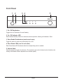
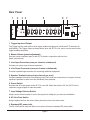
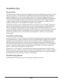
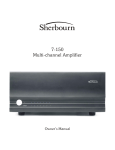
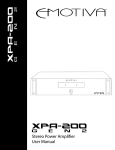
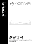
Important Safety Precautions and Explanation of Symbols
!
The exclamation point within an equilateral triangle is intended to alert the user to the presence of
important installation, operation, and service instructions in this manual.
The lightning flash with arrowhead symbol within an equilateral triangle is intended to alert the user
to the presence of uninsulated dangerous voltages within the enclosure that may be of sufficient
magnitude to constitute a risk of electrical shock to the user.
Please read this Installation and Operation Manual thoroughly before attempting to install, configure,
or operate the Sherbourn 4Z-75. After successful installation and configuration of the 4Z-75, be sure to
retain this manual in a safe place for future reference.
Safety is a key component to a long lasting and trouble free installation. Please read and follow
all instructions and heed all warnings on the 4Z-75 and in this manual. The vast majority of the
subsequent safety precautions are common sense. If you are not comfortable with the installation
of audio/video entertainment equipment, you should seek the services of a qualified installation
professional or call us for help.
!
WARNING: TO REDUCE THE RISK OF FIRE OR ELECTRIC SHOCK, DO NOT USE THE
4Z-75 NEAR WATER OR IN WET LOCATIONS, DO NOT EXPOSE IT TO RAIN OR MOISTURE,
DO NOT EXPOSE IT TO DRIPPING OR SPLASHING FROM OTHER SOURCES, AND ENSURE
THAT NO OBJECTS FILLED WITH LIQUIDS (SUCH AS VASES) ARE PLACED ON IT. DOING SO
MAY RESULT IN DAMAGE TO THE 4Z-75 AND THE RISK OF ELECTRIC SHOCK, WHICH MAY
RESULT IN BODILY INJURY OR DEATH.
WARNING: TO REDUCE THE RISK OF ELECTRIC SHOCK, DO NOT REMOVE THE COVER
FROM THE 4Z-75. THERE ARE NO USER-SERVICEABLE PARTS INSIDE THE 4Z-75. REFER ALL
SERVICE TO QUALIFIED SERVICE PERSONNEL.
Do not install the 4Z-75 near or above any heat sources such as radiators, heating vents, or other
apparatus that produces heat. Do not block any ventilation openings or heat sinks. Avoid installing the
4Z-75 directly above other heat-producing equipment unless sufficient ventilation or forced-air cooling
is provided.
Do not install the 4Z-75 in locations without proper ventilation. The 4Z-75 should not be operated
on a bed, sofa, rug, or similar surface that may block vents. The 4Z-75 should not be installed in an
enclosed location such as a bookcase, cabinet, or closed equipment rack unless sufficient forced-air
ventilation is provided.
Always install your 4Z-75 according to the manufacturer’s instructions and only use attachments or
accessories specified by the manufacturer.
Do not install the 4Z-75 on any stand, shelf, or other piece of furniture that is unable to support its
weight. If a cart is used to move the 4Z-75, use caution to avoid injury from tip-over.
Connect the 4Z-75 only to power sources of the correct voltage (as shown in this manual and on the
4Z-75). Ensure that the Input Voltage selector switch on the rear of the 4Z-75 is set to the appropriate
voltage.
Protect power supply cables from being pinched, walked on, or otherwise damaged. Be especially
careful where the power cable enters the power outlet and the 4Z-75 unit.
Only connect the 4Z-75 to an electrical outlet or extension cord of appropriate type and rating.
DO NOT defeat the safety purpose of a grounding or polarized plug by removing ground pins or using
unsafe adapters. A polarized plug has two blades - one wider than the other. A grounding plug has a
third ground prong in addition to the two main conductors. The wide blade or third groundling prong is
provided for your safety. If the provided plug does not fit your outlet, consult an electrician to replace
your obsolete outlet. If you replace the 4Z-75 power cord, only use one of similar type and equal or
greater current rating.
The power cable for the 4Z-75 should be unplugged from the outlet during severe electrical storms, or
when unused for a long period of time.
Only replace the fuse in the 4Z-75 with a fuse of proper value and voltage rating.
The 4Z-75 should only be cleaned as directed in the Installation and Operation Manual. Avoid spraying
liquids directly onto the 4Z-75 and NEVER spray liquids into the vents. Care should be taken so that
small objects do not fall into the inside of the 4Z-75.
!
You should seek service for your 4Z-75 by qualified service personnel if any of the following occur:
1. The power-supply cord or the plug has been damaged.
2. Objects or liquid have fallen or spilled into the vents.
3. The 4Z-75 has been exposed to rain.
4. The 4Z-75 exhibits a marked change in performance.
5. The 4Z-75 has been dropped, or its enclosure or chassis is damaged.
NOTE: TO COMPLETELY DISCONNECT THE 4Z-75 FROM THE AC POWER MAINS,
DISCONNECT THE AC POWER CORD FROM THE AC RECEPTACLE.
NOTE: THE AC POWER CORD FOR THE 4Z-75 MUST REMAIN READILY ACCESSIBLE AT ALL
TIMES.
CAUTION
CAUTION: TO REDUCE THE RISK
OF ELECTRICAL SHOCK, DO
NOT REMOVE COVER. NO USER
SERVICEABLE PARTS INSIDE.
REFER SERVICING TO QUALIFIED
SERVICE PERSONNEL.
4Z-75
Two-Channel Four-Zone Distribution Amplifier
Contents
Important Safety Precautions and Explanation of Symbols
Introduction..................................................................................................2
The Sherbourn 4Z-75..................................................................................2
About This Manual.......................................................................................2
Mechanical and Environmental...................................................................3
Front Panel..................................................................................................4
Rear Panel..................................................................................................5
Inputs and Outputs......................................................................................6
Installation Tips............................................................................................7
Configuration and Operation.......................................................................8
Performance Specifications.........................................................................9
Features....................................................................................................10
Periodic Maintenance................................................................................11
Troubleshooting.........................................................................................12
Sherbourn Technologies, LLC Ten-Year Limited Warranty........................13
Notes.........................................................................................................14
Page 1
Introduction
Thank you for choosing the Sherbourn 4Z-75 Two-Channel Four-Zone Distribution Amplifier.
The 4Z-75 combines two powerful channels of audiophile quality sound with flexible output switching
and the ability to drive even the most difficult loads. The 4Z-75 can run any pair of speakers, or any
combination of pairs of speakers in up to four different zones, with ease - even multiple pairs with
different impedances - as long as the total impedance on each stereo channel remains at or above 2
ohms.
The 4Z-75 uses proven technology, including class A/B circuitry, Sherbourn’s intelligent protection
system, and true commercial grade construction and components, to deliver excellent sound,
superior performance, outstanding reliability, and amazing flexibility. The 4Z-75 is one amplifier that
can solve all of your tricky distribution problems.
The Sherbourn 4Z-75
The 4Z-75 can deliver up to 95 watts / channel into 8 ohms, 150 watts / channel into 4 ohms, or
270 watts / channel into 2 ohms; which you can use to provide power to one very difficult load, or to
run four pairs of 8 ohm speakers in four different zones - each at 65 watts / channel, or to run any
combination of speakers that you need to.
The 4Z-75 has four sets of independently relay-switched stereo speaker outputs, with convenient
front panel controls for each, and a single master Volume control. It also includes a passthrough output for driving additional equipment, and a standard trigger input and output. Speaker
connections are all via full-sized five-way binding posts, and the 4Z-75 uses a convenient removable
IEC power cord.
About This Manual
This manual will provide you with all the information you need to install and configure the Sherbourn
4Z-75 Two-Channel Four-Zone Distribution Amplifier to achieve its optimum potential. The manual
also includes a brief summary of the features offered by the 4Z-75 and a short description of how
the controls work and how to perform common operations.
You may wish to record serial numbers or other purchase information on the Notes page at the back
of this manual.
Page 2
Mechanical and Environmental
SIDE
TOP
18”
SHERBOURN 4Z-75
16.75”
RACK HANDLES
1/16”
17”
19”
FRONT
3.5”
4”
Dimensions:
17” wide x 4” high x 18.25” deep (includes feet, binding posts, knobs, no rack kit)
Weight:
27 lbs / 12.5 kg (unboxed); 38 lbs / 17.5 kg (boxed)
Rack mountable:
Yes, with optional rack mount kit
Power requirements:
115 VAC or 230 VAC +/- 10% @ 50 / 60 Hz (selectable by rear-panel switch)
Ventilation and cooling:
To avoid overheating, be sure to provide adequate clearance and ventilation.
Page 3
Front Panel
1
2
ON / OFF
3 4
5
1
2
3
4
VOLUME
1. On / Off Pushbutton
Toggles the 4z-75 between On and Standby.
2. On / Off Indicator LED
Red indicates Standby mode; blue indicates normal operation; flashing red indicates a Fault.
3. Zone Enable Pushbuttons (one for each zone)
Toggle the status of each zone (individually) On or Off.
4. Zone Status LEDs (one for each zone)
Each Zone Status LED illuminates blue the corresponding zone is enabled.
5. Volume Knob
Sets the output level (gain) for all zones. (The maximum gain on the Volume knob is limited by the
setting of the Master Volume adjustment on the back panel.)
Page 4
Rear Panel
1
2
3 4
5
ZONE 4
TRIGGER
INPUT
OUTPUT
CH2
MASTER
VOLUME
CH1
CH2
6
ZONE 3
CH1
CH2
ZONE 2
CH1
CH2
ZONE 1
CH1
CH2
7
INPUT VOLTAGE
FUSE
CH1
8
IN
POWER
OUT
9
1. Trigger Input and Output
The Trigger Input is used to allow other trigger-enabled equipment to switch the 4Z-75 between On
and Standby. The Trigger Output is always active when the 4Z-75 is On, and is used to control other
trigger-enabled equipment.
2. Master Volume (preset adjustment)
Sets the overall / maximum gain for the 4Z-75 (works in conjunction with the front
panel Volume knob).
3. Line Input Connectors (one per channel; unbalanced)
Connect your stereo input to these connectors.
4. Line Ouput Connectors (one per channel; unbalanced)
Provides a passthrough connector for connecting additional equipment.
5. Speaker Terminals (one pair per channel per zone)
Connect speakers to these five-way binding posts. Each zone has connections for one pair of stereo
speakers; speakers for each zone are individually relay switched.
6. Power Switch
Switches the AC mains power to the 4Z-75 On and Off. When this switch is Off, the 4Z-75 will not
respond to trigger signals or manual controls.
7. Input Voltage Selector Switch
Always ensure that this switch is set for the proper line voltage for your area and installation.
8. AC Line Fuse Holder
Always replace the fuse with a time delay (slow-blow) fuse of the same value.
9. Standard IEC power inlet.
The PA 18-45 can be used with either a two-wire or three-wire standard IEC power cable.
Page 5
Inputs and Outputs
Input sensitivity (for full output into 8 ohms):
800 mV
Analog inputs:
One stereo pair of unbalanced (RCA) inputs.
Analog (line level) outputs:
One stereo pair of unbalanced (RCA) outputs .
Speaker outputs:
8 pairs of full-sized five-way binding posts
(one pair for each channel in each zone; Channel 1, zones 1-4 and Channel 2, zones 1-4).
Minimum recommended load impedance (per channel):
ANY combination that totals 2 ohms or higher per channel.
Trigger and control:
Trigger Input (mono 1/8”).
Trigger Output (mono 1/8”).
Front panel controls and indicators:
On/Off (large push button); toggles Standby mode.
On/Off LED (1); red indicates Standby mode; blue indicates normal operation;
flashing red indicates a fault.
Zone Enable (4 pushbuttons); 1 through 4; individually enable each zone.
Zone Status; LEDs (4); indicate when each zone is enabled.
Volume (knob).
Rear panel controls and indicators:
Power (rocker switch); switches mains power.
Input Voltage (protected slide switch); selects 115 or 230 VAC line voltage.
Master Volume; controls the level of the input .
AC power input:
IEC standard C13/C14 inlet and power cord (two conductor).
Page 6
Installation Tips
Zone Control
The Sherbourn 4Z-75 has two channels of amplification and four separate output zones (four zones;
each zone is stereo). The front panel Zone Enable push buttons each independently connect the
speakers assigned to one zone to the amplifier outputs; the push buttons toggle state and the
indicator LED above each one indicates whether that zone is enabled or disabled. Any combination
of zones may be enabled as long as the overall load on each channel of the amplifier remains at
or above 2 ohms (4 pairs of 8 ohm speakers, two pairs of 4 ohm speakers, or 2 pairs of 8 ohm
speakers and one pair of 4 ohm speakers all satisfy this requirement).
Zone Enable settings persist in Standby mode (when you switch from On to Standby, settings are
stored, and restored when you switch back to On). Zone Enable settings do not persist when the
4Z-75 is completely shut down (either via the rear-panel power switch, or when AC power is
removed altogether). When powered On after a full AC shutdown, the 4Z-75 will return to its default
state (Zone 1 Enabled; Zones 2 - 4 Disabled). The Volume control on the 4Z-75 remains at its
current setting when power is cycled via either the front panel On / Off button or the rear panel
Power switch.
Ventilation and Cooling
Even though the 4Z-75 is quite efficient, it can still produce significant heat, especially when driving
low impedance loads. To avoid overheating, be sure to provide adequate clearance and ventilation,
especially on the top and bottom of the unit, and do not block the vents. Overheating adversely
affects performance and shortens component life. We suggest locating components that produce
the most heat towards the top of your rack if practical, and leaving at least 1U (1.75”) of rack space
between components. Space between components can be left open for ventilation, filled with a
spacer, or used to house a forced-air cooling solution.
Sherbourn’s C-12 Flex Rack™ Cooling System uses whisper quiet high capacity variable speed
fans to provide over 100 CFM of forced air cooling for rack installations. The C-12 offers a variety of
air-flow options (including external ducting), includes professional features like triggered operation
and thermostatic control, and takes up only 2U of rack space.
Rack Mounting Options
The Sherbourn 4Z-75 may be rack mounted using our 2RU rack mount kit.
Page 7
Configuration and Operation
Operating Voltage
Verify that the 4Z-75 is configured for the correct operating voltage for your area. (Voltage is set via
the Input Voltage switch on the rear panel of the 4Z-75).
Trigger and Zone Control Persistence
Volume and Zone Enable settings on the 4Z-75 persist when the power is switched to Standby and
returned to On via the front panel On / Off push button or by the assertion of a signal at the Trigger
Input. When the AC mains power for the 4Z-75 is powered Off using the rear panel Power switch
or via an external power switch, the Volume setting will remain where it was when the 4Z-75 was
powered Off, but the Zone Enable settings will return to the default configuration (Zone 1 Enabled;
Zones 2 - 4 Disabled).
Zone Enable Push Buttons
The front panel Zone Enable push buttons each independently connect the speakers assigned to
one zone to the amplifier outputs; the push buttons toggle state and the indicator LED above each
one indicates whether that zone is enabled or disabled. Any combination of zones may be enabled
as long as the load on each channel of the amplifier remains at or above 2 ohms (4 pairs of 8 ohm
speakers, two pairs of 4 ohm speakers, or 2 pairs of 8 ohm speakers and one pair of four ohm
speakers all satisfy this requirement).
Rear Panel Master Volume Control
The rear panel Master Volume control (located to the left of the input and output RCA connectors)
acts as a preset level control (in addition to the front panel Volume knob). This controls the level of
the input signal, but does not control the level of the analog line level (loop) outputs.
Operating the 4Z-75 in Trigger Mode
When the 4Z-75 is in Standby mode (On / Off LED is lit red), asserting a trigger signal turns the 4Z75 On, and it remains On until the trigger is no longer asserted. If the trigger signal is already active
when mains power is applied, the 4Z-75 will switch On as soon as it completes self-test, and will
switch to Standby when the trigger is no longer asserted.
If the front panel On / Off switch is pressed while the 4Z-75 is On (after being switched on by an
asserted trigger), the On / Off switch will override the trigger and the 4Z-75 will return to Standby
position (even though the trigger is still being asserted). Pressing the front panel On / Off button,
dropping and re-asserting the trigger, or switching the mains power off and on again while the trigger
remains asserted, will then switch the 4Z-75 back to On.
Page 8
Performance Specifications
Analog inputs:
One stereo pair of unbalanced (RCA) inputs.
Analog (line level) outputs:
One stereo pair of unbalanced (RCA) outputs.
Speaker outputs:
8 pairs of full-sized five-way binding posts
(one pair for each channel in each zone; Channel 1, zones 1-4 and Channel 2, zones 1-4).
Minimum recommended load impedance:
ANY combination that totals 2 ohms or higher per channel.
Power output:
95 watts RMS per channel (x2); into 8 ohms.
150 watts RMS per channel (x2); into 4 ohms.
270 watts RMS per channel (x2); into 2 ohms.
Input sensitivity (for full output):
800 mV
S/N ratio:
> 95 dB (A-weighted).
Frequency response:
20 Hz to 20 kHz + / - 0.02 dB at 1 watt (- 1.5 dB at 80 kHz).
Trigger and control:
Trigger Input: 5 - 20 VAC or VDC.
Protection:
The 4Z-75 is protected against excessive operating temperature, shorted speaker connections,
ground faults, and other common fault conditions. If a fault occurs, the 4Z-75 will automatically
power down and the front panel Standby LED will flash red. To reset the protection, turn the 4Z-75
Off and then On again using the On / Off button or the rear panel power switch after the fault has
been removed.
Page 9
Features
The Sherbourn 4Z-75 Two-Channel Four-Zone Distribution Amplifier combines the latest cutting
edge technology with solid engineering and high quality components to deliver superior sound
quality, performance, and features. Some of the more important features of the 4Z-75 include:
•
•
•
•
•
•
•
•
•
•
•
•
•
2 channels of fully discrete, audiophile quality amplification
Each channel delivers:
95 watts RMS per channel (x2); into 8 ohms
150 watts RMS per channel (x2); into 4 ohms
270 watts RMS per channel (x2); into 2 ohms
One set of stereo inputs with loop output for chaining additional amps
4 sets of individually relay-controlled stereo speaker outputs
Front panel master Volume control and output switching controls (with status indicators)
Stable into low impedance loads and other difficult loads
Speaker connections via full sized five-way binding posts
Convection cooled; no fans
Massive toroidal power supply
Intelligent protection from electrical faults
Intelligent protection from thermal faults and overheating
Operates from 115 VAC or 230 VAC (user selectable)
Rack mountable
•
10 year Sherbourn Technologies Limited Warranty
You can find more information about the 4Z-75 Two-Channel Four-Zone Distribution Amplifier on our
website at www.sherbourn.com
Page 10
Periodic Maintenance
The Sherbourn 4Z-75 requires no periodic maintenance.
Cleaning the 4Z-75
•
•
If necessary, the 4Z-75 should be cleaned gently with a soft rag.
If something sticky gets on the front panel or case of the 4Z-75, it should be cleaned with a mild
cleaning solution applied to a soft rag, followed by wiping with a clean rag dampened with plain
water and drying with a soft dry rag or cloth.
Note: DO NOT spray water or cleaning solution directly onto the 4Z-75 or into the vents.
Page 11
Troubleshooting
If problems occur, the first step should be to verify that the 4Z-75 is set to the proper line voltage for
your AC power source, and that your power source is operating correctly.
Problem: No sound is heard from any speaker (the On / Off LED is not lit).
Reason: You have no AC power.
• Verify that the circuit is live and the rear panel Power switch is On.
• Verify that the line cord on the 4Z-75 is fully inserted and is tight.
Problem: Sound is clean but there is insufficient volume
(even when the knob is fully clockwise).
Reason: The rear panel Master Volume adjustment is set too low.
• Adjust the rear panel Master Volume adjustment to a more appropriate setting.
Problem: No sound is heard from any speaker (the On / Off LED is lit red).
Reason: The 4Z-75 is in Standby mode.
• Press the Standby button or assert a signal at the Trigger Input.
Problem: No sound is heard from any speaker
(the On / Off LED is lit blue but none of the Zone Status LEDs is lit).
Reason: None of the zones is enabled.
• Press one of the Zone Enable buttons.
Problem: No sound or distorted sound is heard from one or both channels in one or
more zones (the Status LED is lit blue).
Reason: The 4Z-75 is On and is not indicating a fault.
• Verify that BOTH the front panel Volume and rear panel Master Volume controls are both set
properly (and not all the way down).
• Check your source and your input cabling.
• Check your speakers and speaker connections.
Problem: No sound is heard (the Standby LED is flashing red).
Reason: The 4Z-75 is indicating a fault on one or both channels in one or more zones.
• Verify that the speaker cable(s) and speaker terminals are not shorted.
• Verify that the speaker itself is not shorted or damaged
(try the speaker on another channel and see if the fault “moves”).
• Verify that the source is not faulty
(try that input cable on another input and see if the fault “moves”).
• Disconnect all inputs and outputs and reset the 4Z-75
(turn the rear panel Power rocker switch Off and back On).
If the fault condition persists after all inputs and outputs have been disconnected and the
fault has been reset, AND the Voltage Select switch is in the proper position, please contact
Sherbourn Technical Support.
Page 12
Sherbourn Technologies, LLC Ten-Year Limited Warranty
What does this warranty cover? Sherbourn Technologies, LLC (“Sherbourn”) warrants its
products against defects in materials and workmanship. This warranty is subject to revision at any
time.
How long does this coverage last? This warranty commences on the date of retail purchase
by the original retail purchaser and runs for a period of ten (10) years thereafter, with the following
exceptions: (1) receivers (including the SR-8100, SR-8200, and SR-120), preamp/processors
(including the PT-7030, PT-720C4, and PT-7020), preamplifiers (including the PRE-1), and the
CD-1 CD Player (with the exception of the slot load CD engine) are covered by this warranty for
five (5) years from the date of retail purchase by the original purchaser; and (2) electromechanical
components, including the slot load CD engine on the CD-1 CD Player, and all fans (including
the C-12 Cooling Unit), are covered by this warranty for three (3) years from the date of retail
purchase by the original retail purchaser. This warranty is transferrable, upon written notification
to Sherbourn, to any person that owns the warranted product, however, if ownership is transferred,
the Term shall be no longer than five (5) years from the date of purchase by the original purchaser.
Sherbourn warrants any replacement product or part furnished hereunder against defects in
materials and workmanship for the longer of the following: (i) the amount of time remaining under
the original warranty, or (ii) 120 days from your receipt of the repaired or replaced product. The
duration described in the previous 3 sentences is hereinafter referred to as the “Term”. TO THE
FULLEST EXTENT PERMITTED BY LAW, ALL IMPLIED WARRANTIES RELATED TO THE
ORIGINAL PRODUCT AND ANY REPLACEMENT PRODUCT OR PARTS (INCLUDING IMPLIED
WARRANTIES OF MERCHANTABILITY AND FITNESS FOR A PARTICULAR PURPOSE) ARE
EXPRESSLY LIMITED TO THE TERM OF THIS LIMITED WARRANTY. SOME STATES DO
NOT ALLOW LIMITATIONS ON HOW LONG AN IMPLIED WARRANTY LASTS, SO THE ABOVE
LIMITATION MAY NOT APPLY TO YOU. A claim under this warranty must be made by you within
the Term. A claim shall not be valid (and Sherbourn has no obligation related to the claim) if it is not
made within the Term and if it is not made in strict compliance with the requirements of the “How do
you get service?” section.
What will Sherbourn do? Sherbourn will, at its option, either: (i) repair the product, or (ii) replace
the product with a new consumer product which is identical or reasonably equivalent to the product.
Sherbourn may provide you with a refund of the actual purchase price of the product in the event
(i) Sherbourn is unable to provide replacement and repair is not commercially practicable or cannot
be timely made, or (ii) you agree to accept a refund in lieu of other remedies hereunder. When
a product or part is repaired or replaced, any replacement item becomes your property and the
replaced item becomes Sherbourn’s property. When a refund is given, the product for which the
refund is provided must be returned to Sherbourn and becomes Sherbourn’s property.
What is not covered by this warranty? This warranty does not apply: (i) to damage caused by
use with non-Sherbourn products, where the non-Sherbourn product is the cause of the damage;
(ii) to damage caused by service or maintenance performed by anyone who is not a representative
of Sherbourn; (iii) to damage caused by accident, abuse, misuse, flood, fire, earthquake or other
external causes; (iv) to a product or part that has been modified after its retail purchase, where
the modification caused or contributed to the damage; (v) to consumable parts, such as batteries;
(vi) normal wear tear; or (vii) if any Sherbourn serial number has been removed or defaced and
Sherbourn cannot otherwise confirm that you are the original retail purchaser or authorized
transferee. SHERBOURN SHALL NOT BE LIABLE FOR ANY INCIDENTAL OR CONSEQUENTIAL
Page 13
DAMAGES ARISING FROM OR RELATED TO ANY DEFECTS IN OR DAMAGES TO ITS
PRODUCTS. SOME STATES DO NOT ALLOW THE EXCLUSION OR LIMITATION OF INCIDENTAL OR CONSEQUENTIAL DAMAGES, SO THE ABOVE LIMITATION OR EXCLUSION
MAY NOT APPLY.
How do you get service? In order to make a claim under the warranty, you must:
1.
Call a customer service representative (“CSR”) of Sherbourn at (1-877-EMO-TECH /
1-877-366-8324). Provide the CSR with a description of your problem and the serial number of the
product for which the warranty claim is being made.
2.
The CSR will provide you with a returned material authorization number (“RMA”).
3.
Ship the product to Sherbourn at the following address, with the RMA written in large,
bold letters on the outside of the box, and with the letters “RMA” written before the number. Parcels
arriving without a RMA number on the outside of the box will be refused.
Sherbourn Technologies, LLC
Attn: Repair Department
131 Southeast Parkway Court
Franklin, TN 37064
How does state law apply? This warranty gives you specific legal rights, and you may also
have other rights which vary from state to state. CERTAIN STATES HAVE ENACTED LAWS
WHICH PRECLUDE THE WAIVER OF CONSEQUENTIAL AND INCIDENTAL DAMAGES AND/
OR PRECLUDE THE WAIVER/LIMITATION OF IMPLIED WARRANTIES. TO THE EXTENT YOUR
STATE HAS ENACTED A LAW WHICH PROHIBITS SUCH A WAIVER/LIMITATION, ALL SUCH
WAIVERS/LIMITATIONS CONTAINED IN THIS WARRANTY ARE INAPPLICABLE TO YOU. CERTAIN STATES HAVE ENACTED LAWS WHICH REQUIRE THE DURATION OF A WARRANTY TO
BE EXTENDED (INCLUDING BUT NOT LIMITED TO DURING PERIODS OF REPAIR). TO THE
EXTENT YOUR STATE HAS ENACTED A LAW OF THIS NATURE, THEN THE DURATION OF
THIS WARRANTY WILL BE EXTENDED AS REQUIRED BY APPLICABLE LAW.
Notes
All information contained in this manual is accurate to the best of our knowledge at the time of
publication. In keeping with our policy of product improvement, we reserve the right to make
changes to the design and features of our products without prior notice.
User Manual Revision 1.1
Page 14
Feb 2013