1
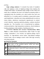
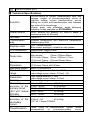
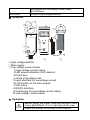
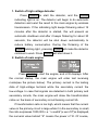
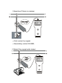
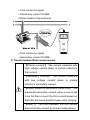
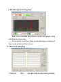
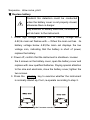
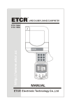
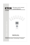
CONTENT
Warning........................................................................................... 1
Ⅰ Introduction ............................................................................... 3
Ⅱ Electrical Symbols..................................................................... 4
Ⅲ Technical Specifications ............................................................ 5
Ⅳ Structure.................................................................................... 7
Ⅴ Operation .................................................................................. 7
1. Switch of high voltage detector ........................................... 8
2. Switch of main engine......................................................... 8
3. Detection on HV current...................................................... 9
4. Detection on LV current......................................................11
5. Transformation Ratio measurement ................................. 13
6. Data keeping and delete ................................................... 15
7. Data storage...................................................................... 15
8. Data search ....................................................................... 15
9. Data deletion ..................................................................... 16
Ⅵ Software .................................................................................. 16
1. Real-time monitoring page................................................ 17
2. Historical data page .......................................................... 17
Ⅶ Replace battery....................................................................... 18
Ⅷ Packing list .............................................................................. 19
Warning
Thanks for purchasing Wireless HV Current Transformation
Ratio Tester from our company. In order to have better use of this
product, make sure that:
——Read this manual carefully; before conducting field tests,
the operator shall fully understand guidelines in this manual
——Comply with safe rules and notices listed in this manual
completely.
u In any cases, safety shall come first when using this Tester,
especially, in which the voltage circuit bears the voltage of AC
100V or more.
u In case that the voltage circuit bearing the voltage over 600V
is to be tested, the Tester shall be applied connecting insulating
rod, with the hand holding on the fifth knot of it.
u Due to risk of high voltage lines, operators shall have
accepted rigid training and gained related certification for high
voltage operation before conducting field test with this Tester.
u Take notice of characters and symbols labeled on the face
board and back board.
u Please do not place or store the Tester under direct sunshine,
in high temperature or moist places or places apt to be dewed.
u Take notice of the polarities of the battery when doing
replacement; remove the battery from the Tester if it is kept idle
for a long time.
u Disassembly and maintenance of this Tester shall be done by
operators with authorization.
u Please do not use Testers whose binding clips and other parts
are broken.
u Avoid attacking binding clips and maintain the Tester regularly.
Soft cloth (e.g. glasses cloth), moistened by clean, antirust and
dehumidified lubricant (e.g. WD-40), instead of corrosive agent
or rough issues shall be used to gently rub down the Tester.
u In case that continuing use will cause safety hazard due to the
performance of the Tester itself, stop using it and mothball it at
once, then leave it to authorized organization for handling.
u When contacting the sign “ ” (dangerous), users shall follow
the directions on the Tester and manual to do safe operation.
u When contacting the sign “
”(extremely dangerous) ,users
shall rigidly follow the directions on the Tester and manual to do
safe operation,
u It is suggested to test the insulating strength for this Tester at
least one time a year.( AC100kV/rms, section between the fifth
knot of insulating rod)
Ⅰ Introduction
ETCR9500 Wireless HV Current Transformation Ratio
Tester breaks through the traditional structure, specializing in
on-line measurement of high-voltage current transformer in service
under 60KV, primary and secondary current of transformers,
transformation ratio, and leakage current(ETCR9500B also with
phase, polar, ratio difference, angle difference Indication). It
consists of high voltage detector, low-voltage secondary current
clamp, main engine, high-voltage insulation rods. The wireless
transmission signal is able to penetrate obstacles, such as walls of
buildings. The signal’s direct-line transmission distance is about
30m. The HV/LV high accuracy clamp ammeter can be used to
measure the current and leakage current varying from 0.01mA to
1000A.HV clamp ammeter can also measure LV current.
Current clamp: In order to make sure of the high accuracy,
stability and reliability during any monitoring at any time the entire
year, special alloy is selected, and latest CT technology plus
magnetic shield technology almost resistant to external magnetic
field are adopted.
Main engine: Gorgeous blue LCD presents you clear
information at a glance and it possesses super large memory
space capable of storing 3,000 sets of data.
Monitoring Software: Functions such as real-time monitoring
and historical data search is available, as well as curve drawing,
ratio, max, min, average indication, alarm value setting .There are
also functions such as data documents saving and historical report
printing.
High voltage detector: It connects five knots of insulation
rods and applies in test of high/low-voltage lines bearing the
voltage below 60KV; its dedicated high-voltage current clamp can
easily clip or withdraw the lines to be tested by pressing down or
unplugging back the insulation rod, which saves time and runs
effectively; so, it is widely used for substation, power plant, power
audit department, industrial and mining establishments as well as
check station, electrician maintenance departments to conduct
current detection, opposing electricity-stealing, outdoors electrical
operation etc. The insulation rod is characterized by lightless,
moisture protection, high temperature resistance, shock resistance,
bending resistance, high insulation, flexibility and so on.
ETCR9500 Wireless HV Current Transformation Ratio
Tester is called Wireless Transformation Ratio Tester for high
voltage; meanwhile it can function as high/low-voltage clip-on
ammeter, for high-altitude current tester, high-altitude leakage
current tester, clip-on leakage current meter with high accuracy
and other products.
Ⅱ Electrical Symbols
Extremely dangerous! Operators shall rigidly follow the
safe rules, or the potential electric shock will cause
personal injury or death.
Dangerous! Operators shall rigidly follow the safe rules, or
the potential electric shock will cause personal injury or
death.
Warning! The safe rule shall be followed completely, or
personal injury or damage to equipments will arise.
Alternating current (AC)
Direct current (DC)
Ⅲ Technical Specifications
Function
Power source
Test way
Transmission
way
Display mode
LCD dimension
Tester size
Clamp
Dimension
Sampling speed
Measurement
range
Resolution
Gearing
Measuring
accuracy of the
primary circuit
(23℃±3℃,below
80%RH)
Measuring
accuracy of the
secondary
circuit
Transformation
On-line testing for current, transformation ratio, and
leakage current of primary/secondary circuit of
high/low voltage current transformation; on-line
testing for current and transformation ratio between
two sides of the transformer
(Phase, polar, ratio difference, angle difference
indication is also available on ETCR9500B)
DC6V alkaline dry battery(1.5V AAA×4) keeps a
continuous work for 30 hours
Clip-on CT
Wireless transmission with direct-line transmission
distance about 30m
LCD: 128dots×64dots;
Blue screen, backlight, suitable for dark places
Display area: 44mm×27mm
Width × Height× Thickness:
Main engine:
75mm×170mm×30mm
HV Current Clamp:76mm×255mm×31mm
LC Current Clamp:175mm×70mm×38mm
HV Current Clamp:φ48mm
LC Current Clamp: φ25×30mm
About 3 times/second
High voltage detector: 0.1mA~1000A
Low-voltage current clamp: 0.01mA~6A
High voltage detector: 0.1mA
Low-voltage current clamp: 0.01mA
Automatic gearing
0.0mA~299mA:
±1%±3dgt
0.30A~49.9A:
±1.5%±5dgt
50.0A~199.9A:
±2%±5dgt
200A~600A:
±3%±5dgt
601A~1000A:
±4%±5dgt
0.00mA~6A:
±1%±3dgt
(23℃±3℃,below 70%RH)
Three kinds
measurement
of transformation ratios:( actual
of
primary/secondary
circuit;
ratio
Data storage
Line voltage
Data hold
Data search
Overflow display
No
signal
instruction
Automatic
shutdown
Battery
voltage
Tester quality
External
interference
Working
temperature and
humidity
Storing
temperature and
humidity
Insulation
rod
size
Length of the
lead
of
LV
current clamp
Insulation
strength
transformation on the basis of secondary circuit
bearing current 5A; transformation on the basis of
10kV-YY of 10kV/380V transformer and the Max. ratio
is 1:100 million (1.0K8)
3,000 sets, press HOLD to hold the data ,number and
store automatically(power
failure or
battery
replacement will not cause data missing)
Test for lines bearing voltage below 60kv (insulating
rods with five knots must be used)
Press HOLD to hold the data, and sign of “Hold”
appears; press it again, holding will be canceled.
Press HOLD and POWER to enter the mode of data
search.
Outrange overflow: “OL A” appears
When the main engine does not receive transmit
signals, present “No Signals”
15 minutes after starting up, the tester will shutdown
automatically
When battery voltage is below 4.8v, sighs will remind
you of replacement
Main engine: about 240g (including battery)
High voltage detector: about 335g (including battery)
Low-voltage needle-point current clamp: about 190g
Total weight: about 2.5kg(including insulation rod and
battery)
No super strong electromagnetic field; no same
frequency interference of 433 MHz and 315 MHz
-25℃~45℃; below 80%Rh
-10℃~60℃; below 70%Rh
φ32mm, 1m/know (standard configuration: five knots),
extendable
Standard: 2 meters (lengthen according to the on-site
length)
High voltage detector: AC100kV/rms(section between
the fifth insulation rod and the clamp core of
high-voltage current clamp)
Structure
Main engine and low-voltage current clamp:
AC1000V/rms
Antidrip II(high voltage detector)
Ⅳ Structure
①
②
③
①High voltage detector
②Main engine
③Low-voltage current clamp
1 High-voltage current clamp
2 LED power indication of HV detector
3 Power key
4 Joints of insulation rods
5 Input interface for low-voltage current
6 LCD monitor of the main engine
7 HOLD key
8 RS232 Interface
9 Output plug for low-voltage current clamp
10 Low-voltage current clamp
Ⅴ Operation
Before using the tester, examine whether there
is any part broken; if no, it can be put into use.
Install the battery according to the manual.
1. Switch of high voltage detector
Press POWER to start the detector, and the POWER
indicating light is on. The detector will begin to do automatic
detection and send the result to the main engine by wireless
transmission. If the indicating light keeps flickering about 15
minutes after the detector is started, this will present an
automatic shutdown and after it keeps flickering for about 30
seconds, the detector will be shut down automatically to
reduce battery consumption. During the flickering of the
POWER indicting light , pressing POWER will make the detector
continue to work. Press POWER will shut down it.
2. Switch of main engine
Press POWER to start the engine, and LCD displays. After
the normal startup, the main engine will enter test receiving
mode(see the picture below). The primary current is the testing
data of high-voltage terminal while the secondary current the
low-voltage. In case that signals are detected in both primary and
secondary circuits, the main engine will show the transformation
ratios on the basis of secondary circuit bearing current 5A.
If transformation ratio is too high, which means that the current
value in the primary circuit is large while it in the secondary is small,
the ratio surpasses 1000,000, i.e. “x.xxxK6”(x.xxx×106)is displayed,
the numeral value behind “K” means the power of 10. Of course,
this phenomenon will not occur in the normal operational circuit.
In data search mode, press POWER key and shift the cursor to
“return”, return to the test mode by pressing the HOLD key, power
off by pressing the POWER key.
3. Detection on HV current
High voltage, very dangerous!Nobody but a
qualified personnel after training could
conduct operation on it. The operator should
obey safety regulations, otherwise there will
be the danger of electric shock resulting in
personal injury or casualty.
Only when all of the five insulating bars are
connected can the high voltage line be
detected, otherwise there may be the danger
of electric shock resulting in personal injury
or casualty.
Dangerous! It is not allowable to measure
high voltage line above 60V, otherwise
there will be danger of electric shock
resulting in personal injury or casualty.
Dangerous! It is not allowable to detect the
high current wire above 1000A.
Prior to the detection, have the insulation
bars connected properly, finally have the
detector connected, for avoidance of any
ground impact on the instrument.
Nothing but the special-made insulation bars
could be connected to the instrument.
After the detection, collect the insulation rod
in slant direction, first take apart the
detector, then the insulation bars for the
avoidance of ground impact on detector
High voltage detector is connected properly with 5
insulation rod and started normally .Set the detected wire at
the center of guide sector on detector pliers head(Diagram A).
High voltage detector has guide sector perpendicular to wire,
Push forward the insulation rod, the wire detected is clamped
by the high voltage detector which starts detection and
feedback to the main set. Main set enter detection and data
collection state after its normal starting up, If the main set
receives the signal sent by the high voltage detector, there will
be a live indication of current amount on high voltage end, If
the main set fails to receive the signal sent by the high voltage
detector, the first current is indicated to be” no signal” for the
primary loop. If the main set has“OL”as its first currency
indication, that means that the first current exceeds the upper
limit of the high voltage detector. Push the insulation rod
backward, the high voltage detector is disconnected with the
wire.(As shown in Diagram C).Do make every effort to keep
the guide sector perpendicular to wire upon withdrawing.
Notice: For the sake of safety, please take
the instrument away from the wire after the
detection is finished.
4. Detection on LV current
High voltage, very dangerous!Nobody but a
qualified personnel after training can
conduct operation on it. The operator should
bear safety regulations in mind, otherwise
there will be the danger of electric shock
resulting in personal injury or casualty.
Low voltage current pliers are not allowable
to detect high voltage wire above 600V or
6A, otherwise there will be the danger of
electric shock resulting in personal injury or
casualty.
1)Connect low voltage current pliers and main set, turn the
main set on, enter the detection mode.
2)Have low voltage current pliers clamp the wire(notice: it
work holding jaws is fully closed),examine the current
numerical reading, if the instrument has secondary current
indication of “OL” ,the secondary current exceeds instrument
upper current limit .
3)Reference illustrations
Clamp electricity wire and zero wire at the same
time, leakage current could be detected.(note: total
2 wires)
Clamp the ground wire, the leakage current could be
measured(note: single wire)
Clamp the main line ,total current amount could be
measured. (note: single wire)
Where its numeral reading is not easily accessible,
use high voltage detector to examine the current on
low voltage wire.
⑴Examine if there is a leaker.
---First current no signal
---Secondary current 35.0MA
⑵Detect the equipments leaker
---First current no signal
---Secondary current 35.0MA
⑶Detect leaker of ground wire
---First current no signal
---Secondary current 35.0MA
5. Transformation Ratio measurement
【Primary current】: The current collected with
high voltage current pliers is mutual inductor’s
first current
【Secondary current】: The current collected
with low voltage current pliers is mutual
inductor’s secondary current.
【Ration based on secondary current 5A】
:The
measured secondary current value is converted
to be 5A,then convert the first current based on
that ratio,the same transformation ratio. Display
【Ratio 】: The ratio between the first current
and secondary current by actual measurement.
【 10kV-YYconversion ratio 】: high voltage
detector collects the secondary bus current,
The ratio between transformer’s
first current
and mutual inductor secondary current could
be calculated by transformer 10kV/380V
As above described, concerning high voltage detector
and the first and secondary return circuit clamped by low
voltage current pliers , the main set has an indication of the
first and secondary current number and tranformation ratio,if
the first current is 680A,the secondary current is 2.00A,its
current ratio is 340.0, calculated based on the secondary
loop circuit 5A,the transformation ratio is 1700/5A,(which is 5
÷2×680),the 10kV/380V transform has a transformation
ratio of 12.9, the first current to the secondary current of
mutual inductor (which is 340÷(10kV÷380V)
)
①
①Detection display mode
②
②Conversion ratio display mode
In detection mode, press the HOLD key for 3 seconds,
enter the conversion display mode as shown above on the
right diagram: the first, second loop current.10kV-YY
conversion ratio. Press the HOLD key for 3 seconds, exit from
the conversion ration display mode, return to the start-up
detection mode.
In the ratio conversion mode, click the HOLD key to set the
second time currency base number, and conversion ratio is
calculated, press the POWER key to shift the cursor. Press the
HOLD key for 3 seconds, exit from the conversion ratio display
mode,return to the start-up detection mode. Each time the
instrument starts up with the secondary current 5A being
the default conversion ratio.
6. Data keeping and delete
In detection mode, press the HOLD key for LCD display
of the HOLD symbol. Press the HOLD key to release the data
lock, return to the detection mode, the “ HOLD ” symbol
disappears.
7. Data storage
In detection mode, press the HOLD key for data holding,
the instrument will store the data and remind you the total
stored data number. The instrument has a data storing
capability of 3000 groups. If the stored data is full, there is a
symbol indication of “ FULL ”, clear the memory for next data
storage.
8. Data search
In detection mode, press both the HOLD key +POWER
key to enter the data search mode, meanwhile the detector will
auto-display the group 0001 data. Now press the POWER key
and shift the cursor, press the HOLD key to confirm. The
instrument are designed with fast search function from“+1、-1、
+10、-10” stored data, press the HOLD key once, search in
increased (reduced) order ,shift the cursor on “+10、-10”
position, press the HOLD key, data number could be increased
or reduced by 100,search and view the cycled data stored
downward or upward.
Shift the cursor to “ESC” the return position, press the
HOLD key, exit from the data search mode, back to the
detection mode.
9. Data deletion
In data search mode, press the POWER key and shift the
cursor to the “delete DEL”position, then press the HOLD key
“YES”to delete all the stored data ,and return to detection
mode,it is not possible to restore the data just being deleted.
Ⅵ Software
The Minitoring and data upload software have to be
installed and run on the computer base on Windows XP/2000
OS.
Monitoring
Software:
Functions
such
as
real-time
monitoring and historical data search is available, as well as
curve drawing, ratio, max, min, average indication, alarm value
setting .There are also functions such as data documents
saving and historical report printing
1. Real-time monitoring page
Red Curve indicates the primary current and green curve
indicates the secondary.
Curve zoom in and out: Click on the left key(no release) of
the mouse and move the mouse.
2. Historical data page
Historical
data
process:read,access,saving,analyse,
Sequence,draw curve, print.
Ⅶ Replace battery
Caution! No detection could be conducted
when the battery cover is not properly closed,
otherwise there is danger.
Pay attention to battery electrode, otherwise it
will do harm to the instrument.
1. When high voltage detector has its battery voltage below
4.8V,its main set flashes with ---.When the main set has its
battery voltage below 4.8V,the main set displays the low
voltage icon, indicating that the battery is short of power,
replace the battery.
2. Power off, confirm that the instrument is shutdown. Loosen
the 2 screws on the battery cover, open the battery cover and
replace with new qualified batteries. Paying special attention
to the size and electrode, close the battery cover, tighten the
two screws.
3. Press the
POWER
key to examine whether the instrument
is normally stared up,if not ,re-operate according to step 2.
Loosen it by turning the 2 screws counter clockwise
Tighten it by turning the 2 screws clockwise
Ⅷ Packing list
High voltage detector
1 unit
Main set
1 unit
Low voltage current pliers
1 unit
Insulation bar(1 M/pc)
5 pcs
Instrument box
1 pc
Manual/warranty card/certification
1 unit
Manufactured by
Guangzhou ETCR Electronic Technology Co., Ltd
Address: B-3F, North Jixian Industrial Park, North Baiyun
Avenue, Guangzhou
Postcode:510440
Tel:086-20-36282512
36282505
Fax:086-20-36282515
Email:[email protected]
Website:http://www.etcr.cc