1
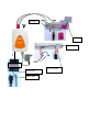
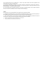
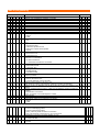
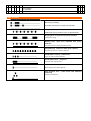
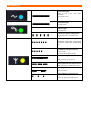
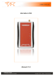
Analog GSM Gateway Link Gate A Premium User manual v1.0 BASIC FEATURES: Link Gate A Premium is dual band GSM Gate based on Telit GL865 GSM module equipped by a lot of adjustable features increased comfort of service. It has been designed for GSM network 850/900/1800/1900 MHz. • Polarity reversal of telephone line allows exact detection of start and end of call. • CLIP support all ordinary protocols and allows send not only incoming call number but also name (when is saved in phonebook). • Call billing allows control exact call duration due tax pulses 12/16 kHz (1. pulse when outgoing call is picked up). • Beep in minute period into the call allows easy identification of GSM call. • Monitoring system allows sending SMS to preprogrammed number when voltage of backup batterie is low, unit is logged to GSM network, no picks up number of ringing called person/connected device doesnt react for ringing) etc. ECHO canceler setting up of local conditions • *Option : • USB cable with PC software allows you easy configuration as same as sending and receiving SMS messages (via SMS mail software)* or data transmission. • Sending of status SMS : 1-30 days (adjustable); Thanks of many Link Gate A Premium features you can satisfy very wide group of customers. By setting of permitted numbers to memory of Link Gate A Premium you can restrict unrequested calls (to public numbers).As same as you can set Link Gate A Premium to provides incoming calls only. INSTALLATION By pressing of yellow button release the SIM card holder. Insert the SIM card and replace the SIM card holder. Before inserting the SIM card we recommend checking at various mobile phone state of the SIM card (logging with or without PIN, PIN, etc.) and set logging without PIN. When you want logging with PIN you have to pre-programmed this PIN and set logging with PIN (via table of programming). Without this setting the Gate wont work. DO NOT FORGET ANTENNA CONNECTION! The available place for installation select up following point of view: 1. Distance from PBX – possibility of GSM interferences to other PBX lines as same as length of line from Gate to PBX (max. 200m) 2. Main 230 V for power supply of Gate 3. Quality of GSM signals at the installation place of GSM Gate. antenna SIM line Analog line USB option Power supply Phone line supply Mini USB Quality of GSM signal The sound quality depends on BTS setting where you are connected by the Gate. To find best place for antenna mounting you can use either mobile phone or feature 29 (table of programming). The suitable signal power is 3 scales of mobile graduation. To check and find best position from GSM signal point of view you can use also GG SET (configuration sw). Connection of antenna MENU SETWhen you connect magnetic antenna keep on mounting at bigger iron subject. This subject makes “against-weight” at its depends the power of radiated signal When you inserted SIM card as same as all cables are connected (do not forget that Link Gate A Premium is connected on external line not on extension) connect device to main 230V. The blue LED of “power supply” is light up within 10 sec. After a while will flash a few times irregularly yellow LED (GSM network registration). Tle CPU then waiting for communication to GSM module (via LED table – communication off). After 30 seconds the yellow LED start flashing up GSM signal strength (via LED table).When pick up connected analogue phone or call to Link Gate A Premium from PBX the LED of analogue line lights up (green LED). In the phone is hearing dial tone of Link Gate A Premium. It is ready to use. The most often problems during Link Gate A Premium compact installation: Ø All LED is not lighting. There is a problem with the power supply. Check connection to main 230V as same as connection of adapter to Link Gate A Premium. Ø The LED “power supply” lights. When you make connection to Gate green LED is ON and in handset you hear busy tone. Yellow LED flashing in period “GSM module doesn’t communicate with CPU“. During work with USB could be programmed fix communication rate for GSM module. Use USB to program rate on “autobauding“. Ø The yellow LED flashing in period “PIN unreadable“. After calling to Link Gate A Premium you get busy tone. The SIM card requires PIN, which is not pre-programmed or is pre-programmed wrongly. Ø The LED „communication to GSM„ is flash shortly one for 2 sec. After calling to Link Gate A Premium you are hearing busy tone. Link Gate A Premium is not log into GSM network – bad signal. Ø The yellow LED “communication to GSM” is flashing up signal strength. After calling to Link Gate A Premium is not light up green LED is not light up and in analogue phone is quiet. It interrupted conduction of analogue line or so much big resistance in current loop (for example: (longer cable between PBX and Link Gate A Premium). Ø The yellow LED „communication to GSM„ is flashing up signal strength“ as same as green LED lights up. The PBX hold “pick up“ line of GSM Gate. By incoming call you can remove this issue. In other cases check PBX manual. Ø The Link Gate A Premium works but call is disturbed by interference. Incorrect position of antenna against telephone line . Change antenna position. Note: Default you make by parameter 99 in programming mode (via programming table at page 11). All LEDs flashing as same as tone types are mentioned in tables at the end of manual. USB You can purchase USB tool for PC configuration of the unit. It is optional. This tool is connected by a 6 wire cable to the units in middle of phone line. (see picture on page 2). You can control the GSM modul direcly by virtual COM port. The Gate you can further uses ordinary GSM modem for data transmission, internet connection or for SMS messages. When unit is working as GSM modem then is busy for voice connection. When you pick up the line you will hear busy tone. The unit is monitoring data transmission by modem. The data transmission can not be permanent therefore the unit stays in data mode 10 seconds after finishing of data transmission. Then is going back to Voice mode (calling) The same is when you are calling over unit. It is busy for data transmission. The optional sw supply to unit for sending and receiving SMS messages is SMS mail. It is working under Outlook, Outlook Express, Opera etc. And you can work with SMS as with normal e mails. ( see manual for SMS mail). It works in batches and allows programs communication interval (1 to 99 minutes) to Link Gate A Premium for sending and receiving SMS. Due this we avoid situation that unit is permanently blocked by data mode for voice communication. Further functionality of USB is monitoring Link Gate A Premium operation. It is possible a record even incoming call includes time and CLIP, signal strength, etc… CONFIGURATION The programming mode is set after acknowledgement dialling to Link Gate A Premium. In the analogue phone is waiting tone. After password inserting is tone changing to programming tone. Then you can programming each features of Link Gate A Premium (via table of programming) Progress of programming: Dial 2 digits number of programming feature. Dial 1 to 4 digits number for feature value programming. Wait for a tone of confirming request (3 shorts tones). Confirm the feature by dialling acknowledgement (#) Wait for confirming tone. Follow programming tone again. Finish programming by hang up a phone. Example: programming of new permitted fix numbers (02) to memory 09: Dial acknowledgement (default is #). In phone you are hearing waiting tone ( password (default 0000). Waiting tone is changing to programming tone ( ). Dial ). Dial 1902. Wait for tone of confirming request (3 shorts tones). Confirm the feature by dialling acknowledgement (#). Wait for confirming tone (one long tone). Finish programming mode by hang up a phone. Warning: After dialling of parameter value you have to wait for 3 short tones and then dial acknowledgement (#). Wait for long tone confirms acceptation of this parameter. Notes to each parameters: 11 – 19 When you program some prefixes the Link Gate A Premium allows outgoing calls starts by those prefixes only. The others will get busy tone. When memories will be empty the calling won’t be restricted (default). Memory of prefixes can content 1 digit only. If you insert 1 digit only the Link Gate A Premium will check first position only. Rewriting of memory – by storing of new fix numbers are old fix-numbers erased. Erasing of memory -‐ Memory you will erase by storing of „nothing“. You dial only number of memory which you want erase and confirm it. 22 Very important features is acknowledge character setting. Default is #. When is # used for PBX features you can change it on *. 24 An analogue phones are not enable send “+” which is very used in GSM. In this case is possible to use combination “00” to send it to mobile phone. 31 This feature identificated connection of Link Gate A Premium to external line at some type of PBX (ex : Siemens Hicom). 29 This feature is used for searching of antenna best position. After feature activation you get tones immediately. You end the feature by hang up. 32, 35 The GSM phones requested command to connection on inserted number. The Link Gate A Premium will send a command immediately after acknowledge character dialling (#). Notes: Programming is only by tone dial DTMF. Don’t forget set even external line at PBX. ! Changes are valid after hang up only (finishing of programming mode). It is very important especially in acknowledge character changes- till hang up you must use previous acknowledgement. ! After numbers dialling you must wait for confirming request, insert acknowledge character and wait for confirming tone. When you insert acknowledge character before wont be accepted. ! Switch to programming mode is possible even in busy tone. ! Some parameters are possible by software only Table of programming Dial Number 0 0 n n 1 1 n n 1 2 n n 1 3 n n 1 4 n n 1 5 n n 1 6 n n 1 7 n n 1 8 n n 1 9 n n 2 1 n 2 2 n 2 3 n 2 5 n 2 6 n n n n n n n n n n n n n n n n n n n n n Password nnnn to programming mode access Memory x for permitted fix number(1 to 4 digits) Reversal polarity n=0 OFF n=1 ON Acknowledge character setting n=0 # n=1 * Type of dial tone n n=0 permanent tone n=1 dial tone up table of tone n=2 dial tone of public lines operator n=3 quiet Signalization to the call – short tone each minute n=0 tone is turn off n=1 tone is turn on Restriction of call duration Default 0 0 0 0 0 0 0 0 n=0 without restriction 2 7 n 2 8 n 2 9 n 3 1 n 3 2 n n 3 3 n n 3 5 n n 3 3 3 7 8 9 n n n x 7 1 x 7 7 2 3 n n 7 4 n n y n y n=1 call duration restricted at 10 minutes PIN n=0 start without PIN n=1 start with PIN Outgoing DTMF Inband/Outband n=0 Inband DTMF n=1 Outband DTMF Indication of signal power. Power is indicate by frequency of short tones. Max. frequency is 5/sec Echo canceller n=0 echo canceller is OFF n=1-3 level (efficient) of echo canceller Waiting for last number nn sec (01 to 15) (after finishing of dial by acknowledge character is sending immediately) Waiting nn sec. for dial after pick up (00 to 99 it is 9.9 sec.)(“0” waiting is not limited) Number of dialled numeral, after it is dial send immediately (length of telephone number) nn=00 function none active nn=01-19 number of numeral telephone number Storing of PIN Amplification of sound in outgoing direction (1 to 4) CLIR feature, switching off outgoing CLIP (#31#) n=0 OFF n=1 ON xx=00 No charging pulses xx=12 12 kHz charging pulses xx=16 16 kHz charging pulses yy=00 1 pulse only at the moment of connection yy=01 to 99 seconds. Pulses each 01 up to 99 seconds Amplification of sound in incoming direction (1 to 4) n=0 CLIP is switch OFF n=1 FSK CLIP Bell Call progress tone n=0 OFF 0 0 0 0 6 0 0 0 0 1 0 0 0 1 1 0 0 7 5 9 9 n n=1 ON Roaming n=0 prohibited n=1 permitted Default setting Table of tones Dial tone (up setting) Link Gate A Premium is ready to accept dial Busy tone – short tone repeated Called part is busy, doesn’t exist, not permitted,etc... Ringing tone- long tone and pause repeated Called part is ringing Waiting tone- short tone repeated with quick cadence. Link Gate A Premium waiting for password insert Programming- short tone with quick cadence Programming mode of Link Gate A Premium Confirmation inquiry- 3 short tones Inquiry to confirm inserted parameter Confirmation tone – long tone Parameter was saved correctly Minute tone – short tone with 1 minute period Minute beep to inform about GSM call Call progress tone - short tones with different frequency Searching of called part LED signalling LED signalling Permanent light (lights up after connection) LED signalling LED signalling signalling LED ¤¤¤¤¤¤¤¤¤¤¤¤¤¤ LED signalling ¤¤¤¤¤¤¤¤¤¤¤¤¤¤ LED signalling ¤¤¤¤¤¤¤¤¤¤¤¤¤¤ ¤¤¤¤¤¤¤¤¤¤¤¤¤¤ ¤¤¤¤¤¤¤¤¤¤¤¤¤¤ ¤¤¤¤¤¤¤¤¤¤¤¤¤¤ ¤¤¤¤¤¤¤¤¤¤¤¤¤¤ ¤¤¤¤¤¤¤¤¤¤¤¤¤¤ ¤¤¤¤¤¤¤¤¤¤¤¤¤¤ ¤¤¤¤¤¤¤¤¤¤¤¤¤¤ ¤¤¤¤¤¤¤¤¤¤¤¤¤¤ ¤¤¤¤¤¤¤¤¤¤¤¤¤¤ ¤¤¤¤¤¤¤¤¤¤¤¤¤¤ ¤¤¤¤ ¤¤¤¤ ¤¤¤¤ ¤¤¤¤¤¤¤¤¤¤¤¤¤¤ ¤¤¤¤ ¤¤¤¤ ¤¤¤¤¤¤¤¤¤¤¤¤¤¤ ¤¤¤¤ ¤¤¤¤ ¤¤¤¤¤¤¤¤¤¤¤¤¤¤ ¤¤¤¤ ¤¤¤¤ ¤¤¤¤ ¤¤¤¤ ¤¤¤¤ ¤¤¤¤ ¤¤¤¤ ¤¤¤¤¤¤¤¤¤¤¤¤¤¤ ¤¤¤¤ ¤¤¤¤ ¤¤¤¤¤¤¤¤¤¤¤¤¤¤ ¤¤¤¤ ¤¤¤¤ ¤¤¤¤ ¤¤¤¤ ¤¤¤¤ ¤¤¤¤ ¤¤¤¤ ¤¤¤¤ ¤¤¤¤ ¤¤¤¤ ¤¤¤¤ 13 13 13 13 13 13 3 sec. After power Power supply of unit Permanent light (lights up after power connection) Power supply of GSM unit Permanent light Permanent light (lights up after power connection) Power supply of GSM unit Line OFF HOOK Permanent Permanent light light line OFFupHOOK Permanent light (lights after power connection) (lights afterofpower connection) Power up supply GSM unit Doesn’t light Permanent light Power supply of GSM unit line OFF HOOK Doesnt light Line ON HOOK Permanent light line ON HOOK Permanent light (lights up after power connection) Permanent light Flashing in rythm of busy tone (lights after connection) Permanent light Power supply ofpower GSM unit line OFFup HOOK Doesnt light Power supply of GSM unit line OFF HOOK Flashing in rhytm of busy or PC connection mode line ON HOOK Programming tone Programming or PClight connection mode Doesnt light Permanent Flashing Flashing in rhytm of busy in rhytm of busy tone. line ON HOOK Doesnt light Permanent light line OFF HOOK Flashing in rhytm of busy tone line ON Initialization mode after power supply OFFHOOK HOOK tone Programming or PC connection mode connection, restart after programming Initialization powerof supply connection, Flashingmode in after rhytm busy Doesnt etc.. Flashing in of tone restart afterlight programming etc.. Flashing in rhytm rhytm of busy busy Doesnt line ON HOOKlight tone Programming or PC with connection mode 4 sec. tone 15 flashes period line ON HOOKmode after power supply connection, Initialization Programming or PC connection mode stand by mode. Flashing in rhytmetc.. of busy restart of after programming Number flashes signal strength Flashing in=rhytm of busy with period 4 sec tone 1-5 flashes Flashing in rhytm of busy 15 flashes with period 4 sec. tone Flashing in light rhytm busy Permanent Initialization mode after powerof supply connection, tone stand by mode.or isPCrunning tone Programming connection mode Stand by mode GSM connection (call) restart after programming etc.. Initialization mode power supply Number of flashes signal strength Programming or PC=after connection mode connection, Short lights offNumber with 2 15 flashes with period sec. restart after programming etc.. Flashing in light rhytm of period busy of4flashes=signal strenght Permanent sec. stand by mode.in rhytm tone Flashing of busy 15 flashes with period 4 sec. GSM connection is running (call) Permanent GSM modul doesnt communicate to CPUconnection,light Number of flashes signal strength Initialization mode =after power supply tone stand by mode. Short lights offpower with period 2 restart after programming etc.. Flashing in period 2sec Initialization mode after supply Permanent light Number of flashes = signal strength connection, sec. restart after programming etc..connection SIM not readed GSM is running (call) GSM 15isconnection flashes with period 4 sec. is running (call) Permanent GSM modul doesnt light communicate to CPU stand5connection byflashes mode. Short flashes inwith period 24sec. lights off period 2 1with period sec. GSM is running (call) Flashing 2sec Number ofmode. flashes =period signal strength sec. Gate notinregistrate to GSM stand byis Short off with period SIM ismodul notoflights readed Short network GSM doesnt=light communicate to lights CPU 2 off with period 2 sec Number flashes signal strength Permanent sec. flashes in period 2 sec. Short GSM connectioninis light running (call)2sec Flashing period Permanent GSM modul doesntregistrate communicate to CPU GSM modul doesn‘t communicate to CPU Gate is readed not GSM SIM isconnection not GSM is running (call) to Short lights off with period 2 network Flashing in period 2sec Flashing in2period 2sec sec. flashes period 2 sec. Short lights offin with period SIM not readed GSMismodul doesntregistrate communicate to to CPU Gate is not GSM sec. Short in period sec. network GSM modulflashes doesnt communicate to CPU2readed Flashing in period SIM is2sec not Gate is readed not registrate to GSM SIM is not Flashing in period 2sec network SIM is notflashes readed Short in period 2 sec. in period 2 sec. Short flashes Gate isflashes not registrate to GSM Short in period 2 sec. network Gate is not registrate to GSM Gate is not registrate to GSM network network Technical parametres: Type Link Gate A Premium Operating position various Operating conditions temperature: +5° C ÷ +40° C, Humidity: 10% ÷ 80% at 30° C Dimensions (mm) 140*97*37 Weight Part of power supply 215g Supply voltage 8-12V (AC/DC) (adapter) Protection thermal fuse in adapter Safety group ČSN EN 60950 group 2 Analogue telephone line Telephone interface 2-wires Telephone connector RJ 11 Impedance 600 Ω ± 20% Dial tone DTMF tt > 30 ms Billing 12/16 kHz Start and end of connection Polarity reversal Supply conduction symmetrical 24V Current loop max 29 mA Resistance of subscribers conduction max. 500 Ω Ringing 55 Vef / 50 Hz Signalization 425 Hz ±20Hz CLIP FSK Bell GSM: Mobile network Provider USB Quad band (850/900/1800/1900Mhz) according SIM card (3V and 1.8 V) version 1.1, virtual COM