1
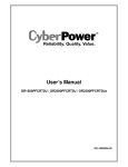
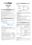
REPLACING THE BATTERY
LIFETI
PR O
SURGE
Y
PROTECTOR
RANT
AR
1. Remove the right side
front panel
2. Remove the one retaining
screw of the cable protection
cover.
CT W
CAUTION! When replacing batteries, replace with the same number of the
following battery size: 12V/7AH for EP-400-UPS-8HTR-1000 and 12V/9AH
for EP-400-UPS-8HTR-2200. There is risk of explosion if the battery is
replaced by an incorrect type. Before replacing batteries, remove conductive
jewelry such as chains, wrist watches, and rings. Do not dispose of batteries
E
DU
M
Read and follow these IMPORTANT SAFETY INSTRUCTIONS before
servicing the battery. Service the battery under the supervision of someone
knowledgeable of batteries and their precautions. Servicing the battery
can only be performed by trained personnel.
3. Remove the cable protection
cover.
EP-400-UPS-8HTR-1000 & 2200 Manual and Instructions
Episode® Rack Mount 8-Outlet, 2U Uninterruptible Power Supply AVR with RJ45 - RG6
released material is harmful to the skin and eyes and may be toxic. To
(or 15 amps, depending on model) maximum branch circuit overcurrent
protection in accordance with the National Electric Code, ANSI/NFPA 70.
Take the following precautions before replacing the battery:
1. Remove all watches, rings or other metal objects.
2. Only use tools with insulated handles and do not lay tools or
metal parts on top of battery or any terminals.
4. Disconnect the black
4. Wear rubber gloves and boots and safety goggles.
and red cable
5. Determine if the battery is inadvertently grounded, and remove source of
ground if necessary. CONTACT WITH A GROUNDED BATTERY CAN
RESULT IN ELECTRICAL SHOCK! The likelihood of such shock will be
reduced if such grounds are removed during installation and maintenance
(applicable to a UPS and a remote battery supply not having a grounded circuit).
Read thoroughly and follow all instructions carefully before attempting to unpack, install, or operate this UPS unit.
BOX CONTENTS
5. Remove the three
retaining screws.
6. Pull out the old battery pack
and replace. Reassemble the
retaining screws, covers, black
and red cable, and front panel
in the reverse sequence of the
above steps. Recharge the unit
for 4-8 hours to ensure maximum
UPS battery runtime.
FCC Notice
This device complies with Part 15 of FCC Rules. Operation is subject to the following two conditions: (1)This device may not cause harmful interference, and (2) this device must accept any
interference received, including interference that may cause undesired operation.
WARNING!! This equipment has been tested and found to comply with the limits for a Class B Digital Device, pursuant to Part 15 of FCC Rules. These limits are designed to provide reasonable
protection against harmful interference in residential installation. This equipment generates, uses and can radiate radio frequency energy and, if not installed and used in accordance with the
instructions, may cause harmful interference to radio communications. However, there is no guarantee that interference will not occur in a particular installation. If this equipment does cause harmful
interference to radio or television reception, which can be determined by turning the equipment off and on, the user is encouraged to try to correct the interference by one or more of the following measures: (1) Reorient or
relocate the receiving antenna. (2) Increase the separation between the equipment and receiver. (3) Connect the equipment into an outlet on a circuit different from that to which the receiver is connected. (4) Consult the
(1) UPS Unit; (1) User’s Manual for UPS; (2) Rack Mount Brackets; (2) Stands;(1) Telephone Cable; (1) Emergency Power Off Cable;
(1) PowerPanel® Business Edition Software CD; (2) Serial Interface Cable (DB-9); (1) USB A+B type cable
IMPORTANT SAFETY INSTRUCTIONS
contaminants.
2. To reduce the risk of electric shock, do not remove the cover except to service the battery. There are no user serviceable parts inside except for battery.
3. Hazardous live parts inside can be energized by the battery even when the AC input power is disconnected.
4. The UPS must be connected to an AC power outlet with fuse or circuit breaker protection. Do not plug into an outlet that is not grounded.
If you need to de-energize this equipment, turn off and unplug the unit.
5. To avoid electric shock, turn off the unit and unplug it from the AC power source before servicing the battery or installing a computer component.
(or 15 amps,depending on model)
in accordance with the National Electric Code, ANSI/NFPA 70.
DO NOT USE FOR MEDICAL OR LIFE SUPPORT EQUIPMENT! Episode does not sell products for life support or medical applications. DO NOT use in any circumstance
that would affect operation, safety of any life support equipment, any medical applications or patient care.
DO NOT USE WITH OR NEAR AQUARIUMS! Condensation from the aquarium can cause
SNAPAV™ SURGE PROTECTOR EQUIPMENT WARRANTY POLICY (LIFETIME/ 2 YEAR)
SnapAV™ Surge Protector Lifetime Product Warranty
SnapAV warrants to the purchaser of any standard SnapAV™ surge protector that the surge protector shall be
free of defects in design, material, or workmanship, and SnapAV will repair or replace any defective unit. For
product replacement, see “NOTIFICATION” below.
Lifetime Replacement Policy
Valid only in the United States and Canada. If your SnapAV™ surge protector becomes damaged while
protecting your connected equipment, you may request an equivalent replacement to the latest technology
of that product category. Keep a copy of the original invoice to verify the product belongs to the original
purchaser.
Warning Notice
WARRANTY LIMITATION FOR INTERNET PURCHASERS: SnapAV™ products purchased outside of SnapAV™
internet website do not carry a valid Connected Equipment Protection Policy unless purchased from an
Authorized SnapAV Dealer.
CAUTION: Audio/Video, computer and/or telephone system installations can be very complex systems,
which consist of many interconnected components. Due to the nature of electricity and surges, a single
protector may not be able to completely protect complex installations. In those cases, a systemic approach
using multiple protectors must be employed. Systemic protection requires professional design. AC power,
satellite cables, CATV cables, or telephone/network lines entering the system that do not pass through this
surge protector will render the SnapAV connected equipment protection policy null and void. For additional
information on how to protect your system, please contact SnapAV before connecting your equipment to the
surge protector.
SnapAV™ Surge Protector Connected Equipment Protection Policy
Valid only in the United States and Canada. It is the policy of SnapAV™ that it will, in its sole discretion, replace,
If connected equipment damage was indicated on your RA request, SnapAV™ will request the make and
model of all connected equipment, a connection diagram of your system, as well as other requests based on
the extent of the request for product placement or payment for connected equipment damage. All requests
are too large for a UPS.
disconnecting your equipment.
4. DETERMINATION OF FAILURE: SnapAV will evaluate the protector for surge damage. The protector must
AUTOMATIC VOLTAGE REGULATOR (AVR)
protection capability. Opening the enclosure, tampering with, or modifying the unit in any way shall be
grounds for an automatic denial of your request for payment. SnapAV™, after evaluating all information
provided, shall, in its sole discretion, determine whether or not your request is eligible for payment.
If the surge protector shows no signs of AC power or signal line surge damage and is working within design
and notifying you of the rejection
of your claim. SnapAV™ reserves the right to inspect the damaged connected equipment, parts, or circuit
boards. SnapAV™ also reserves the right to inspect the customer’s facility. Damaged equipment deemed
The EP-400-UPS-8HTR-1000 and EP-400-UPS-8HTR-2200 can stabilize consistent utility power. The incoming utility power may be damaging to
important data and hardware, but Automatic Voltage Regulation helps protect equipment from experiencing damaging voltage levels. An Automatic Voltage Regulator
automatically regulates low or high voltages to keep equipment working at safe AC power levels without switching to battery. Your equipment can operate
normally even during power problems, such as short brownouts and blackouts. The unit’s sealed lead-acid batteries will provide power only if the incoming voltage
drops below 80V or increases above 150V.
5. REQUEST PAYMENTS: Once SnapAV™ has determined that you are entitled to compensation, SnapAV™ will,
at its election, pay you the present fair market value of the damaged equipment, or pay for the cost of the
repair, or send you replacement equipment, or pay the equivalence of replacement equipment.
What is GEMTech?
6. OTHER INSURANCE/WARRANTIES: This coverage is secondary to any existing manufacturer’s warranty,
implied or expressed, or any insurance and/or service contract that may cover the loss.
7. EXCLUSIONS: THE SNAPAV™ SURGE PROTECTOR EQUIPMENT POLICY DOES NOT APPLY TO: Service charges,
installation costs, reinstallation costs; setup cost; diagnostic charges; periodic checkups; routine maintenance;
loss of use of the product; costs or expenses arising out of reprogramming or loss of programming and/or
Green Energy Management technology
The patented energy-saving design in this product reduces energy consumption by up to 75% compared to conventional designs. Conventional UPS systems pass power
costs and unwanted heat. By contrast, the circuitry in our unit bypasses the transformer when utility power is normal. This bypass mode uses less energy and emits less heat.
When utility power is detected to be abnormal, the unit automatically switches modes to operate like a conventional UPS with an AVR. Since utility power operates normally
abuse or misuse, and products subject to manufacturer’s recall or similar event.
is damaged by an AC power, cable, telephone, or lightning surge while connected to a properly installed
SnapAV™ surge protector. SnapAV must determine that the surge protector shows signs of surge damage or
8. DISPUTE RESOLUTION: Any controversy or claim arising out of or relating to SnapAV™ Surge Protector
Equipment Policy, or the alleged breach thereof, shall be settled by arbitration administered by the American
circumstances failed to protect your connected equipment.
HARDWARE INSTALLATION GUIDE
THIS POLICY IS SUBJECT TO THE CONDITIONS BELOW:
a single arbitrator, and will be limited solely to the dispute or controversy between you and SnapAV™. The
arbitration shall be held in any mutually agreed upon location in person, by telephone, or online. Any decision
1. PROOF OF PURCHASE REQUIRED: SnapAV’s™ connected equipment policy extends to the original purchaser
of the SnapAV™ product only and is non-transferable. Original purchase receipts must accompany any product
return or claim for connected equipment damage.
be entered thereon in a court of competent jurisdiction. The arbitrator shall not award either party special,
exemplary, consequential, punitive, incidental or indirect damages, or attorney’s fees. The parties will share
2. PROPER INSTALLATION: SnapAV™ AC protectors must be directly plugged into a properly grounded 3-wire
AC outlet. Extension cords, non-grounded two prong adapters, or other non-SnapAV™ surge products must
not be used. Building wiring and other connections to protected equipment must conform to applicable
codes (NEC or CEC). No other ground wires or ground connections may be used. All wires (including, e.g.,
AC power lines, telephone lines, signal/data lines, coaxial cable,) leading into the protected equipment must
equipment to be protected must be indoors in a dry location, and in the same building. SnapAV installation
instructions and diagrams must be followed.
3. NOTIFICATION: You must notify SnapAV™ within fourteen days of any event precipitating a request for
product replacement or payment for connected equipment damage. A return authorization (RA) number
the amount of the initial claim.
9. GENERAL: If you have any questions regarding the product warranty or the connected equipment
protection policy, please contact the SnapAV™ Technical Support ay 866.838.5052. This warranty supersedes
all previous warranties. This is the only warranty provided with the protector and any other implied or
Product Warranty
Episode® Power Products have a Lifetime Limited Warranty. This warranty includes parts and labor repairs
on all components found to be defective in material or workmanship under normal conditions of use.
before returning the protector to SnapAV™. At this time, you must notify SnapAV if you believe you have a
claim for damaged connected equipment.
to be repaired under this warranty must be returned to SnapAV or a designated service center with prior
Once you obtain a RA number, please mark the number on the bottom of the unit and pack it in a shipping
carton/box with enough packing material to protect it during transit. The RA number must also be clearly
marked on the outside of the carton. Ship the unit to SnapAV™. Please note that you are responsible for any
and all charges related to shipping the unit to SnapAV™.
Battery Warranty
2 years Limited- Batteries will be free of defects in design, material, or workmanship. SnapAV™ will replace any
defective battery
to ensure that the batteries’ maximum charge capacity. To recharge the batteries, plug the UPS into an AC outlet.
2. When you use the included software, connect either the serial or the USB cable between the computer and the corresponding port on the UPS. Note: If the USB port
is used, the serial port will be disabled. They cannot be used simultaneously. The computer with the PowerPanel® Business Edition S/W connects to the USB port or
the Serial port on the UPS. It can control the operating schedule, battery test, outlet, etc. and get information on the UPS status. However, other computers with
PowerPanel® Business Edition S/W can only get UPS status information via a LAN connection.
3. With the UPS off and unplugged, connect your equipment into the outlets. DO NOT plug a laser printer, copier, space heater, vacuum, paper shredder or other large
The power demands of these devices will overload and possibly damage the unit.
4. To protect a fax, telephone, modem line or network cable, connect the telephone or network cable from the wall jack outlet to the jack marked “IN” of the UPS. Then,
connect a telephone cable or network cable from the jack marked “OUT” on the UPS to the modem, computer, telephone, fax machine, or network device.
5. Plug the UPS into a 2 pole, 3 wire grounded receptacle (wall outlet). Make sure the wall branch outlet is protected by a fuse or circuit breaker and does not service
equipment with large electrical demands (e.g. air conditioner, refrigerator, copier, etc.). Avoid using extension cords.
6. Press the power switch to turn the UPS on. The Power-On indicator light will illuminate. If an overload is detected, an audible alarm will sound and the UPS will emit one
long beep. In order to reset it, turn the unit off and unplug some equipment from outlets. Make sure your equipment carries a load current within the unit’s safe range (see
HARDWARE INSTALLATION GUIDE CONT.
LCD STATUS AND SETUP FUNCTIONS
7. Your UPS is equipped with an auto-charge feature. When the UPS is plugged into an AC outlet, the battery will be automatically charging, even when the unit is switched off.
1. General Mode:
a. Press the “Display” button to check the status of the UPS.
b. Press and hold the Display toggle for 4 seconds:
- If machine is in Battery Mode, it will enter Mute status.
- If machine is in Line Mode, it proceeds Self Test.
c. If the Display toggle remains untouched for over 30 seconds,
the LCD backlight will turn off automatically.
8. In order to maintain an optimal battery charge at all times, leave the UPS plugged into an AC outlet at all times.
9. Before storing the UPS for an extended period of time, turn the unit OFF. Then cover it and store it with the batteries fully charged. Recharge the batteries every three months
to ensure good battery capacity and long battery life. This may also prevent damage to the unit from unlikely battery leakage.
10. The unit provides one Primary Serial Port (I), Secondary Serial Port (II), and one USB port, (paired with the Primary Serial Port), to allow connection and communication between
the unit and any attached computers. The Primary Serial Port (I) as well as its paired USB port allow for bi-directional communication among the UPS and the primary connected
computer running the PowerPanel® Business Edition S/W provided. The UPS can control the computer’s shutdown in case of an emergency, and at the same time, the computer
can monitor the UPS and alter its various programmable parameters. On the other hand, secondary Serial Port II only allows the UPS to initiate the connected computer’s smart
auto-shutdown in case of an emergency.
11. EPO (Emergency Power Off) Port: Use the
provided cable to connect to the special
EPO contact switch. Follow the appropriate
circuit diagram (right) to wire the cable to your
a switch installed in an outside area, connected
to the unit via an ordinary RJ-11 phone line.
In case of an emergency, it can be used to
immediately cut-off power from the UPS.
®
®
BASIC OPERATION
2
PRODUCT FEATURES
2. Power On Indicator: Indicates the power is on.
7
5. Battery Backup Protected Outlets: Provides eight battery powered, surge protected
and AVR outlets for connected equipment and ensures temporary uninterrupted
operation of connected equipment during a power failure.
Critical /Non-critical: When the UPS is overloaded, the circuit breakers will be tripped
to interrupt the power supply to the uncritical outlets while continuing to supply the
critical outlets. As well, as the battery capacity depletes under the threshold value,
the uncritical outlets will be shut down and provide energy for critical outlets. The
threshold can be determined and set by users. Non-critical outlets can also be turned
on/off manually through the software package provided.
10. Protected Communication Ports RJ11/RJ45: Ports protect standard single line
modem, fax, telephone line or network cable.
V
3
NONCRITICAL
LOAD
4
9
12 11
CRITICAL
LOAD
IN
OUT
8
Push To
RESET
WIRING
FAULT
EPO
Push To
BATTERY
RESET
+ SURGE
AC INPUT
C
1000
Push To
5
US
Serial Port I
(PRIMARY)
13
Serial Port II
IN
14
10
6
11. Site Wire Fault Indicator: This LED will illuminate to warn the user that a wiring
problem exists within the AC receptacle, such as a bad ground or reversed
wiring. If illuminated, disconnect all equipment and contact an electrician to
ensure outlet is properly wired.
12. Coax/Cable/DSS Surge Protection: The Coax/Cable/DSS surge protection ports
will protect any cable Modem, CATV converter or DSS receiver.
DEFINITIONS FOR ILLUMINATED LCD INDICATORS:
INPUT voltage meter: Measures the AC voltage that the UPS system is receiving from the utility wall
outlet. The INPUT voltage readout can be used as a diagnostic tool to identify poor-quality input power.
The AVR in this UPS continuously conditions the power to a stable 110/120V output to connected
equipment. In the event of a complete power loss, severe brownout, or over voltage, the UPS relies
on its internal battery back up to supply a consistent 110/120V output.
OUTPUT voltage meter: Measures, in real time, the AC voltage that the UPS system is
providing to the computer, such as normal line mode, AVR mode and battery back up mode.
Note: The OUTPUT voltage readout displays the status of the battery back-up outlets.
BATTERY icon: During a severe brownout or blackout, this icon appears and an alarm sounds (two short beeps
followed by a pause) to indicate the UPS is operating from its Internal batteries. During an extended brownout or
blackout that drains the battery, a continuous alarm will sound (and the BATT. CAPACITY readout will show a single shaded segment, equaling 20% battery
capacity remaining) indicating the UPS batteries are nearly out of power
equipment immediately.
Estimate Run Time
Min
AC Input Plug Type
Nema 5-15P
Load Capacity
%
Cable Length
10 ft
Battery Capacity
%
Operating Temperature
32ºF to 95ºF (0ºC to 40ºC)
Automatic Voltage Regulation
Yes
Centigrade
°C
Fahrenheit
°F
BATT. CAPACITY meter: Displays the approximate charge level (in 20% increments) of the UPS’s internal battery. During a blackout or severe brownout and the
UPS switches to battery back up power, the BATT. CAPACITY icon appears and the charge level decreases.
LOAD CAPACITY: Displays the approximate output load level (in 20% increments) of the UPS’s battery outlets.
Nema 5-20P
Amperage
15
20
AC Outlets & Plug Type
8 x Nema
5-15R
8 x Nema
5-20R
1000
2170
700
1600
b. Battery Pack Numbers: Provides the estimated UPS runtime using various numbers of battery packs.
The default setting is 0.
UPS Topology
Line-Interactive
Operating Humidity
0%~95% non condensing
c. Static Frequency Tolerance: There are 6 settings. The default setting is +/-6%.Functional description: The
setting may be adjusted to the quality of the electricity in use.
Storage Temperature
5ºF to 113ºF (-15ºC to 45ºC)
Number. of RJ11/ RJ45 Connectors
1 pair (1-in, 1-out)
Step 4: To save the value and return to general mode, press and hold
the toggle for 4 seconds.
Item
Unit
Delay Time
Min
Battery Pack Numbers
Static Frequency Tolerance
Slew Rate
Battery Shutdown Voltage
The UPS does not
perform expected
runtime.
The UPS will not
turn on.
PowerPanel®
Personal Edition is
inactive
(all icons are gray).
1
COAXIAL Gold Plated “F” Connectors
Yes
Coax/Cable/DSS Surge Protection Yes
A
Coaxial Breakdown Voltage
300V
%
Coaxial Bidirectional?
Yes
Hz
V
TROUBLE SHOOTING
Outlets do not
provide power
to equipment.
310 V for RJ11, 6.8 V for RJ45
Coaxial No. of Pairs
< 1 dB (rated for DSS) (up to
2.0 GHz)
1. Wait for the backlight to turn off OR 2. Press and hold the “Display” toggle for 10 seconds.
PROBLEM
RJ11/ RJ45 Clamping Level
Coaxial Insertion Loss
Note: If user wants to return to general mode without saving changes, there are two methods:
Input Voltage Range (VAC)
80~150
Output Plug Style
Right Angle
Resettable Circuit Breaker
Yes (2 resettable circuit
breakers)
Number of Total Outlets
8
Number of Surge & Battery
Backup Outlets
8
Battery Voltage (VAC)
120 +/- 7% (pure sine wave)
Line Frequency (Hz)
60 +/- 3
Battery Frequency (Hz)
50/60+/-1%
SOLUTION
Battery Waveform
Sine wave
Circuit breaker has tripped due to an
overload.
Turn the UPS off and unplug at least one piece of
equipment. Wait 10 seconds, reset the circuit breaker
by depressing the button, and then turn the UPS on.
Overload Protection
On Utility: Circuit Breaker
On Battery: Internal Current
Limiting
Transient Response Time (ms)
< 4 millisecond
Batteries are discharged.
Recharge the unit for at least 4 hours.
1874
Unit has been damaged by a surge
or spike.
Contact SnapAV™ about replacement batteries at
866.838.5052.
Single Pulse Energy Dissipation
(Joules)
Peak Impulse Current (Amps)
65000A
Uncritical outlets have turned off
automatically due to an overload.
Push the toggle button to make the uncritical outlets
turn on.
Noise Filtration Range
100KHz ~ 100MHz
Recharge the battery by leaving the UPS plugged in.
Battery Runtime at Half Load
(min)
32
Battery not fully charged.
Battery is worn out.
Contact SnapAV™ about replacement batteries at
866.838.5052.
The on/off switch is designed to
prevent damage by rapidly turning it
off and on.
Turn the UPS off. Wait 10 seconds and then turn the
UPS on.
POSSIBLE CAUSE
The unit is not connected to an AC
outlet.
The unit must be connected to a 110/120v 60Hz
outlet.
The battery is worn out.
Contact SnapAV™ about replacement batteries at
866.838.5052.
Mechanical problem.
Contact SnapAV™ at 866.838.5052
The USB cable is not connected.
Connect the USB cable to the UPS unit and an open
USB port on the back of the computer.
The provided USB cable must be used.
The unit is not providing battery
power.
Shutdown your computer and turn the UPS off. Wait
10 seconds and turn the UPS back on. This should
reset the unit.
The cable is connected to the wrong
port.
Try another port of the computer.
The serial cable is not the cable that
was provided with the unit.
Replace with provided USB cable.
SILENT MODE icon: Appears whenever the UPS is in silent mode. The buzzer does not beep during silent mode until the battery reaches low capacity.
FAULT icon: Icon appears if there is a problem with your UPS.
63 lb.
Output Watts
AVR (Automatic Voltage Regulation) icon: Appears whenever your UPS is automatically correcting low AC input line voltage without using battery power. This
is a normal, automatic operation of your UPS, and no action is required.
OVER LOAD icon: Appears and an alarm sounds to indicate the battery-supplied outlets are overloaded. To clear the overload, unplug some of your equipment
from the battery-supplied outlets until the icon turns off and the alarm stops.
2U
Output VAC
ESTIMATE RUN TIME: Displays the run time estimate of the UPS with the current battery capacity and load.
NORMAL icon: Appears when the UPS is working under normal conditions.
52 lb.
Rack Size
a. Delay Time: Delay between switching from Battery Mode to Line Mode. There are 9 different
settings. The default setting is 0 minutes.
13. Serial Port I: Serial port allows connection and communication between the UPS
and the computer.
14. Serial Port II: Serial Port II relays information to equipment that can utilize a
contact closure UPS.
Weight
Hz
Note: If the machine is left idle for over 30 seconds during setup,
the backlight will turn-off and return to general mode automatically.
OUT
17.25 x 15.75 x 3.5 (LXWXH)
Kw
UNINTERRUPTIBLE
POWER SUPPLY
E187679
6G48
+ SURGE
RESET
R
2200
Product Dimensions
Load
LISTED
BATTERY
SPECIFICATIONS
Output Frequency
The settable items are sorted by unit as in the following table:
Step 3: Press and hold the toggle for 4 seconds. When the icons blink,
the value of each item can be changed by slightly pressing the toggle.
SELECT
displays on the LCD.
9. USB port: USB communication port for management software.
Output Voltage
ON/OFF
4. LCD Display Toggle Button: The button can be used to toggle between different data
8. Input Circuit Breaker: Resettable circuit breakers provide Input outlets optimal
overload protection.
V
e. Battery Shutdown Voltage: This function adjusts the UPS shutdown point according to the battery voltage.
3. LCD Module Display: LCD shows all the UPS information with icons and messages.
7. Output Circuit Breaker: Resettable circuit breakers provide Output outlets protection
from overload.
Unit
Input Voltage
d. Slew rate (Dynamic Frequency Tolerance): There are 5 different settings, and the fault value is 4Hz/ sec.
Functional Description: “Slew Rate” indicates the tolerance of a device in accepting frequency variance.
The lower “Slew Rate” results in less tolerance, but better protection for the connected loads.
1
1. Power Switch: Master on/off switch for equipment connected to the UPS.
6. Input Power Cord: Heavy-duty, extra long power cord.
2. Set-up Mode
Step 1: The machine enters Set-Up Mode after holding the Display
toggle for 10 seconds. Icons 3,4,5,6,7,8 light to indicate Set-Up Mode.
Step 2: By pressing the Display toggle, users can switch between
setup functions.
Item
Battery Runtime at Full Load (min) 11
Battery Typical Recharge Time
(Hours)
16
6
8
Battery Type
Sealed Lead Acid
Battery Size
12V/7AH
User Replaceable Battery
Yes
Replacment Battery
RBP832S
Battery Qty
4
PRODUCT COMPLIANCE (UL,
FCC, RoHS, CE)
UL 1778 (UPS) cUL, 107.1
FCC, Class B, RoHS
UL 498 LISTED
(Attachment plugs and receptacles)
Yes
UL FILE NUMBER and/or CSA
FILE NUMBER
E187679
Cable Type
USB
Software
PowerPanel® Business Edition
12V/9AH
RBP842S