1
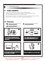
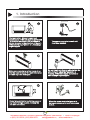
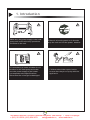
BM FAN COIL UNIT
INSTALLATION AND
USER'S MANUAL
Before operating the unit,
please read the manual carefully.
Keep this manual well for future reference.
Поставка и монтаж тепловых насосов Компания "Реалсолар" г. Санкт-Петербург.
т. (812) 921-5296, (812) 924-3678
[email protected], www.realsolar.ru
Поставка и монтаж тепловых насосов Компания "Реалсолар" г. Санкт-Петербург.
т. (812) 921-5296, (812) 924-3678
[email protected], www.realsolar.ru
Catalogue
1. Introduction
1.1
General Information
1
1.2
Precautions
1
1.3
Features
4
1.4
Operation Temperature Range
4
2. Installation
2.1
Transportation and handling
5
2.2
Handling instructions
5
2.3
Dimension
6
2.4
Part name
9
2.5
Location
10
2.6
Attention for installation
11
2.6.1
Necessary tool for installation
11
2.7
Accessories
11
2.7.1
One accessory box in right side
11
2.7.2
The other accessory box in the left side
12
2.7.3
Check the accessory
13
2.8
Different installatio n
14
2.8.1 Wall mounting
14
2.8.2
16
Floor standing
2.8.3 Horizontal mounting(optional)
16
2.8.4
Water connection
18
2.8.5
Filter
20
2.8.6 Insulation
20
2.8.7 Setting up the condensate drainage system
21
Поставка и монтаж тепловых насосов Компания "Реалсолар" г. Санкт-Петербург.
т. (812) 921-5296, (812) 924-3678
[email protected], www.realsolar.ru
2.9
Test run
21
2.9.1
Air purging
21
2.9.2
Per Start-up
22
2.9.3
Unit Start-up
22
3. Operation Instructions
3.1
Wired controlled
23
3.2
Operation instructions
24
3.3
Protection
28
3.4
Remote controller
29
4. Precautions
4.1
Precautions
30
4.2
Cleaning the air filter
30
4.3
Check and clean the air inside water system occasionally
31
4.4
Drainage
31
4.5
Service to electric parts
31
4.6
Service to fan blade and fan motor
32
5. Appendix
5.1
Exploded view
33
5.2
Wiring diagram
35
5.3
Technical Data
36
Поставка и монтаж тепловых насосов Компания "Реалсолар" г. Санкт-Петербург.
т. (812) 921-5296, (812) 924-3678
[email protected], www.realsolar.ru
1. Introduction
1.1 General Information
Thank you for choosing our product. Please read this manual
carefully before use and follow the instructions to operate the unit in order
to prevent damages on the device or injuries to staff.
Specifications are subject to change with product improvements without prior notice.
Please refer to the sticker on the unit for upgraded specifiactions.
1.2 Precautions
Warning
Prohibition
Caution
Children should be supervised to
ensure that they do not play with the
appliance.
Use a dedicated socket for this unit,
otherwise malfunction may occur.
User
manual
Oil
Gas
Keep the unit away from the combustible
or corrosive environment.
Be sure to read this manual before use.
01
Поставка и монтаж тепловых насосов Компания "Реалсолар" г. Санкт-Петербург.
т. (812) 921-5296, (812) 924-3678
[email protected], www.realsolar.ru
1. Introduction
grovnd line
The installation, dismantlement and
maintenance of the unit must be performed
by qualified personnel. It is forbidden to
do any changes to the structure of the unit.
Otherwise injury of person or unit damage
might happen.
The power supply to the unit unit
must be grounded.
Make sure no water or other liquid drips
into the electric box of the unit Otherwise
the unit might be damaged.
Do not insert any foreign objects into the
all outlet grill when the fan motor is
running. Otherwise injury of person or
unit damage might happen.
Do not clog air inlet or outlet by paper or
any other foreign objects, to keep the
unit well ventilated.
When the power cord gets loose or is
damaged,always get a qualified person
to fix it.
02
Поставка и монтаж тепловых насосов Компания "Реалсолар" г. Санкт-Петербург.
т. (812) 921-5296, (812) 924-3678
[email protected], www.realsolar.ru
1. Introduction
Make sure the power supply to the heat
pump unit is off before any operations
are done on the unit.
If there is a burning smell or in thunder
stop the unit and cut the power, weather.
It is mandatory to use a suitable circuit
breaker for the heat pump and make
sure the power supply to the heater
corresponds to the specifications.
Otherwise the unit might be damaged.
Children should be supervised to
ensure that they do not play with the
appliance.
03
Поставка и монтаж тепловых насосов Компания "Реалсолар" г. Санкт-Петербург.
т. (812) 921-5296, (812) 924-3678
[email protected], www.realsolar.ru
1. Introduction
1.3 Features
1 . 4 Operation Temperature Range
Operation mode
Heating/Cooling
Room temperature
Water inlet temperature
Min
Max
Min
Max
5℃
32℃-60%U.R./R.H.
4℃
80℃
04
Поставка и монтаж тепловых насосов Компания "Реалсолар" г. Санкт-Петербург.
т. (812) 921-5296, (812) 924-3678
[email protected], www.realsolar.ru
2 . Installation
2.1 Transportation and handling
! Danger!
Do not open or tamper
the packaging before installation.
The units should only be moved and
lifted by specialised personnel
trained in these operations.
Check on arrival that the unit has
not been damaged during transport and
that it is complete with all its parts.
To remove the packaging, follow these instructions:
1.Check for visible damage
2.Open the packaging.
3.Check that the packet containing the user's manual is inside.
4.Dispose of the packaging material in accordance with current legislation, at the
appropriate waste reception or recycling site.
2.2
Handling instructions
! Danger!
Movement of the unit should be performed with care, in order to avoid damage to the
external structure and to the internal mechanical and electrical components.
Also make sure that there are on obstacles or people along the route, to avoid the
danger of collisions or crushing and to prevent the lifting or handling device from
turning over.
All the operations listed below must be carried out accordance with current health
and safety regulations, both as regards the equipment used and as regards the
procedure followed. Before commencing moving operations, check that the lifting
apparatus has ths required capacity for the unit in question.
■ Storage conditons
Always check the stickers on the package for the direction of te storage and the
number that can be stacked.
05
Поставка и монтаж тепловых насосов Компания "Реалсолар" г. Санкт-Петербург.
т. (812) 921-5296, (812) 924-3678
[email protected], www.realsolar.ru
2 . Installation
2.3 Dimension
The fan coil unit without motorized water valve
Connect water
pipe on the right side
Model no.
BM150*-NW
BM350*-NW
BM450*-NW
BM550*-NW
A(m m)
694
894
1094
1294
Connector size
Net weight(Kg)
16
22
28
32
G1/2"
G1/2"
G1/2"
G1/2"
06
Поставка и монтаж тепловых насосов Компания "Реалсолар" г. Санкт-Петербург.
т. (812) 921-5296, (812) 924-3678
[email protected], www.realsolar.ru
2 . Installation
2.3 Dimension
The fan coil w ith two-way valve
Connect water
pipe on the right side
Model no.
A(m m)
Connector size
BM150*-2W
BM350*-2W
BM450*-2W
BM550*-2W
694
894
1094
1294
G1/2"
G1/2"
G1/2"
G1/2"
Net weight(Kg)
16
22
28
32
07
Поставка и монтаж тепловых насосов Компания "Реалсолар" г. Санкт-Петербург.
т. (812) 921-5296, (812) 924-3678
[email protected], www.realsolar.ru
2 . Installation
2.3 Dimension
The fan coil with three-way valve
Connect water
pipe on the right side
Model no.
BM150*-3W
BM350*-3W
BM450*-3W
BM550*-3W
A(m m)
694
894
1094
1294
Connector size
Net weight(Kg)
16
22
28
32
G1/2"
G1/2"
G1/2"
G1/2"
08
Поставка и монтаж тепловых насосов Компания "Реалсолар" г. Санкт-Петербург.
т. (812) 921-5296, (812) 924-3678
[email protected], www.realsolar.ru
2 . Installation
2.4
Part name
Air outlet grille
Wired controller
Left panel
Front panel
Right panel
Feet assembly
Air inlet grille
Feet assembly
09
Поставка и монтаж тепловых насосов Компания "Реалсолар" г. Санкт-Петербург.
т. (812) 921-5296, (812) 924-3678
[email protected], www.realsolar.ru
2 . Installation
2.5 Location
In order to obtain optimum efficiency and performance, and to prevent any failures or
hazardous situation, the location must meet the following requirements:
1)For floor standing, the minimum distance between air outlet grille and other objects is
140mm. The distance from side panel to the wall is no less than 20mm to make it easy to
remove the side panels.
2)For wall mounting, the unit should be mounted no less than 80mm higher than floor.
3)For ceiling installation, the unit needs to be at least 2.5m far away from the floor, and
don't allow to blow the cold air to the body directly. The wall should be strong enough to
support the unit.
4)The clearance between air inlet grille and other objects is around 400mm. the unit should
lean a little bit(≤2 degrees) to the area of water discharge for good condensate discharge.
If the wall can't support the weight of 28kg, the unit can't be installed on the wall. It's suggested
to put the unit on the floor, with the feet to support the weight.
Other object
unit:mm
Wall mounting
Ceiling mounting
10
Поставка и монтаж тепловых насосов Компания "Реалсолар" г. Санкт-Петербург.
т. (812) 921-5296, (812) 924-3678
[email protected], www.realsolar.ru
2 . Installation
2.6 Attention for installation
The installation must be performed by qualified and professional installer. Before
any operation on the unit, make sure the power supply to the unit is cut.
2.6.1 Necessary tool for installation
φ6 -φ8 drill bit
measuring reel
" + " type screwdriver
drill bit
Scissors
Spanner
2.7 Accessories
2.7.1 One accessory box in right side
(1)Press " PRESS " on the operation panel, then the operation panel will bounce (fig. 1 and
fig. 2).Screw out 2pcs screws under the operation panel(fig. 3), simply remove the side
corner slight to the right so as to make the reference of the upper profile, and then lift the
right panel upwards and pull it out.
1
2
3
4
b
a
remove 2pcs screws
11
Поставка и монтаж тепловых насосов Компания "Реалсолар" г. Санкт-Петербург.
т. (812) 921-5296, (812) 924-3678
[email protected], www.realsolar.ru
2. Installation
(2)Take out the accessory box in the right side(refer fig. 5).
5
take out the
accessory box
Check the accessory box
2.7.2 The other accessory bag in the left side
1. Use screwdriver to remove 2pcs screws on the left and right side of air outlet grille, and
then take off the air outlet grille(refer fig 1 and 2).
2. Open the baffle plate on the left side, remove 2pcs screws(refer fig. 3), simply remove the
side corner slightly to the right so as to make the reference of the upper profile, and then lift
the left panel upwards and pull it out.
3. Take out the accessory bag from left side(refer fig. 5).
1
2
screw out
the screws
3
4
2
b
screw out
the screws
5
check the
accessory
take out the
accessory box
a
12
Поставка и монтаж тепловых насосов Компания "Реалсолар" г. Санкт-Петербург.
т. (812) 921-5296, (812) 924-3678
[email protected], www.realsolar.ru
2. Installation
2.7.3 Check the accessory
Quantity
Name
Feet
2
Baffle plate for fee
2
Expansion bolts
4
Plastic explosive bolt+Gasket
2
Screws- ST4.1X10
8
Sensor fixture
1
Gasket
1
Spring ring
2
Flat ring
2
Machinary screw(M4X12)+
Flat ring
2
Positioning board
1
Name
Quantity
Remark
Remark
Note: The accessories along with the
unit are different according to
different installation ways. It
depends on different
requirements from customer.
Drain pipe
1
User manual
1
Ribbon
2
Remote controller with
battery inside(only available
for some models)
A :floor standing or wall mounting
installation for A series.
1
Rubber soft pipe
1
1、 φ6 Plastic explosive bolt×2
2、 φ8 Metal expansion bolt×2
3、 Gasket×2
Copper drain pipe
1
Fixture plate for drain
pipe
1
Stainless steel coil
2
user manual
B:Horizontal mounting on the ceiling
1、Expansion bolts×4
2、Copper drain pipe×1
3、Rubber soft pipe ×1
13
Поставка и монтаж тепловых насосов Компания "Реалсолар" г. Санкт-Петербург.
т. (812) 921-5296, (812) 924-3678
[email protected], www.realsolar.ru
2 . Installation
2.8 Different installation
2.8.1 Wall mounting
Take out the positioning board from accessory. Please put the positioning board up
against the wall. According to the anchor point ②.
1. After a suitable place for installation is selected, the unit must be fastened to the wall
in place by two expansion bolts in each side. To fasten the unit to a wooden wall, use
suitable bolts.
2. Mark on the wall where the mounting holes will be drilled. Drill the wall with a power
drill.Put the ∮8 explosive bolts in the holes, mount the gasket on expansion bolt to
avoid the friction between unit and wall.
3. Mount the unit on the explosive bolts(refer fig. 3) and position the unit properly using
a spirit-level, so that it slightly bend to the area of water discharge for good condensate
discharge.
Positioning Board
Unit : mm
≥8 0
1
Model
A
B
BM 1 5 0 * - * W 1 2 94 1147
BM 3 5 0 * - * W 1 0 94 947
8 94
BM 5 5 0 * - * W 6 94
BM 4 5 0 * - * W
747
547
C
964
764
564
364
The positioning board is available for all kinds of installations.
Please choose the corresponding anchor point according to
different installations:
①—Horizontal mounting
②—Wall mounting
③—Floor standing
14
Поставка и монтаж тепловых насосов Компания "Реалсолар" г. Санкт-Петербург.
т. (812) 921-5296, (812) 924-3678
[email protected], www.realsolar.ru
2 . Installation
2
OK!
3
4
Fasten the
expansion bolts
in each side
Mount the unit on the
metal expansion bolts
5
6
Use two plastic
explosive bolts
to fix the unit in
lower side
Fasten the unit
by plastic
explosive bolts
15
Поставка и монтаж тепловых насосов Компания "Реалсолар" г. Санкт-Петербург.
т. (812) 921-5296, (812) 924-3678
[email protected], www.realsolar.ru
2 . Installation
2.8.2 Floor standing
①Fix the feet on the unit by fastening the screws on two sides of feet.After a suitable place
is selected, put the unit against the wall, fasten expansion bolts on left and right side of
back panel to fix the unit on the wall. Mount the gasket on expansion bolt to avoid the
friction between unit and wall.
1
2
② Installation of baffle plate for feet
Please insert the baffle plate into the feet after
water connection is finished(Water connection
according to the chapter 2.8.4).
The depth for inserting the baffle plate into the
feet can be adjusted according to the thickness
of base board, so that the baffle plate can be
close to base board.
2.8.3 Horizontal mounting(optional)
Horizontal mounting is only available for some models which
has special drain pan for installation under ceiling.
1. the unit must be fastened to the ceiling, using expansion
φ8
φ8
φ8
φ8
bolts on each side. To fasten the unit to a wooden ceiling,
use suitable bolts.
2. Take out the positioning board from accessory. According
to the anchor points ① in the chapter 2.8.1, Mark on the
ceiling where the mounting holes will be drilled. Drill 4 holes
in order to insert the expansionbolts. Put the expansion bolts
(∮8) in the holes, mount the gasket on the expansion bolt to
avoid vibration between unit and ceiling.
16
Поставка и монтаж тепловых насосов Компания "Реалсолар" г. Санкт-Петербург.
т. (812) 921-5296, (812) 924-3678
[email protected], www.realsolar.ru
2 . Installation
3. Mount the unit on the expansion bolts and position the unit properly using a spirit-level,
so that it slightly lean(≤2 degrees) to the area of water discharge, for good condensate
discharge(refer fig. 2).
2
lean 2 °
air inlet
air outlet
The unit is horizontal mounting under ceiling
Heat exchanger coil
2°
it slightly bend to the area of water
discharge for good condensate
discharge.
air inlet
air outlet
Drainage
BM
4.Connect the drain hose for condensate(refer fig.3).
Find a rubber
soft pipe in the
accessories
Use a fixture plate
to fix the copper drain
pipe.
Connect the copper
drain pipe to rubber
soft pipe
Connect the other side
of rubber soft pipe to
the water outlet of
drain pan.
17
Поставка и монтаж тепловых насосов Компания "Реалсолар" г. Санкт-Петербург.
т. (812) 921-5296, (812) 924-3678
[email protected], www.realsolar.ru
2 . Installation
2.8.4 Water connection
Note: the water pipe mustn't beyond the range of side panel, otherwise the side panel can't
be installed back.
After the unit is installed in place, connect water inlet and outlet pipes according to the
stickers on the unit. Please refer local safety requirements for safety purpose. After
installation, please check the leakage, clean the unit etc, to meet the local regulations
before usage.(Note: water pipe is suggested to use stainless steel corrugated pipe).
Water pipes passing through the ground
Water pipes passing through the wall
water inlet
water inlet
water outlet
water outlet
连管 安 装 步 骤 如 下 :
Installation steps:
⑴. Take off the sealing cover of water inlet/outlet pipe.
1
2
Take off the
sealing cover
Take off the
sealing cover
⑵. Connect the unit to water system, the inlet/outlet water pipe is suggested to use
stainless steel corrugated pipe, choose the water pipe in proper length to connect
the unit to water system.
18
Поставка и монтаж тепловых насосов Компания "Реалсолар" г. Санкт-Петербург.
т. (812) 921-5296, (812) 924-3678
[email protected], www.realsolar.ru
2 . Installation
Note: The gasket seal must be put on the connector jointing, then fasten the screws
nuts by spanner , to make sure there is no leakage in the joint.
1
2
Note: To connect the water inlet/outlet of the unit to water pipe, it's necessary to use a
spanner to fix the water inlet/outlet, and use another spanner to screw up the
connector of water pipe into the water inlet/outlet. Don't use only one spanner
to do this operation, otherwise the water pipe of the unit would be damaged by
turning round.
3
5
⑶.Connect the smaller end of drainpipe to the outfall of auxiliary drain pan, then fasten
the jointing by ribbon.
1
small
3
2
big
19
Поставка и монтаж тепловых насосов Компания "Реалсолар" г. Санкт-Петербург.
т. (812) 921-5296, (812) 924-3678
[email protected], www.realsolar.ru
2 . Installation
2.8.5 Filter
! It's suggested to install a 60~80 mesh filter on the water inlet of the unit, to keep high
quality of water and collect impurity contained in the water. Make sure keep the water
filter mesh downwards. Check valve is recommended so that the filter can be cleaned
or changed in an easier way.
BM fan coil
Tap water inlet
Check valve
Filter
Drain pipe
Ball valve
BM fan coil
Filter
Water inlet
2.8.6 Insulation
All the water piping must be insulated with insulation no less than 9mm thick.
But all the valve switches need to keep outside for
future use. The insulation must be fastened by tape,
without any gap.
20
Поставка и монтаж тепловых насосов Компания "Реалсолар" г. Санкт-Петербург.
т. (812) 921-5296, (812) 924-3678
[email protected], www.realsolar.ru
2 . Installation
2.8.7 Setting up the condensate drainage system
The condensate drainage system must be set up with
an adequate decline, to ensure the water drain away
properly. Following are directions for setting up a
Connect to the unit condensate
discharge or defrosting tray
proper condensate drainage system:
Notice: To check if water flow is in correct direction,
it's commended to pour some water into the
drain pan very slowly. If the water can't
drain away smoothly, some adjustment
should be made.
Connect to discharge system
2.9
Test run
8mm
2.9.1 Air purging
1.After finishing the installation, proceed
with the following steps to discharge the
air in the unit:
①. Take out the air outlet grille .
②. Open all the valves of water system
and start the water pump.
③. Open air purging valve, and check the
water in a transparent pipe connected
with the valve. If the transparent pipe is
filled with water without any bubbles, the
air is completely purged from the coil.
Air purging valve
Then close the purging valve.
21
Поставка и монтаж тепловых насосов Компания "Реалсолар" г. Санкт-Петербург.
т. (812) 921-5296, (812) 924-3678
[email protected], www.realsolar.ru
2 . Installation
2.9.2 Per Start-up
Before starting up the unit, a certain number of verifications must be preformed on the
installation to ensure that the unit will operate under the best possible conditions.
The check list below is not exhaustive and should only be used as a minimum reference
basis:
①.Make sure fan rotates freely.
②.Inspect all water piping for flow direction.
③.Verify all system piping is correct for operation as per installation requirement.
④.Check voltage of the unit power supply and make certain voltage is within authorized
limitations.
⑤.Make sure the unit is properly grounded.
⑥.Check the presence of protective and breaking devices.
⑦.Check all electric connections for tightness.
⑧.Check all piping for leaks and air is well ventilated.
2.9.3 Unit Start-up
After ensuring all electric connections confirm to the local regulations, follow the
Operation Instructions to start-up the unit.
After start-up the unit, if there is a abnormal sound, please shut off the power supply
immediately to ensure the safety of the unit.
22
Поставка и монтаж тепловых насосов Компания "Реалсолар" г. Санкт-Петербург.
т. (812) 921-5296, (812) 924-3678
[email protected], www.realsolar.ru
3 . Operation Instructions
3.1
Wired controlled
PRESS
ON/OFF
Light, Time, Timer
parameter setting
/SET
Temperature
checking/working
mode
Fan speed, Sleep,
Confirm
increase time, parameter,
temperature, and unlock
Decrease time, parameter,
temperature
Meaning
Symbol
Meaning
Symbol
Heating mode
Temperature or parameter
Cooling mode
Degree Celsius
Auto mode
Water valve
Dehumidify mode
Valve for radiator
Electric heater(reserved function)
Sleep mode
Fan mode
Timer
Lock
Fan speed
23
Поставка и монтаж тепловых насосов Компания "Реалсолар" г. Санкт-Петербург.
т. (812) 921-5296, (812) 924-3678
[email protected], www.realsolar.ru
3 . Operation Instructions
3.2 Operation instructions
1.Standy
In standby status,the unit doesn’t work,but show air inlet
temperature.The following status are in standby:
The unit is standby,when it’s fed with power.
When unit is running,press“ ”once to become standby again.
2.ON/OFF
In standby status,press “ ”for 3seconds to ture on he unit.
Press “ ” for 3 seconds again to turn off the unit.
When the unit is turned on,air inlet temperature,working mode,
fan speed and water valve status show on the display.
3.Unlock
When the unit is turned on,all the buttons will be locked after
no operation for 30 seconds “ ” show on the display,then all
the buttons are invalid.Press “ ”for 3 seconds to unlock all
the buttons.“ ”disappears.
4.Mode selection
When unit is turned on,press “M ”to choose working mode.It
comes in the sequence:
5.Temperature setting
When the unit is turned on,press“ ”or “ ”to enter the target
air temperature setting.Press“ ”once,the target temperature
increases by 1℃.Press“ ”once,the target temperature
decreases by 1℃.
24
Поставка и монтаж тепловых насосов Компания "Реалсолар" г. Санкт-Петербург.
т. (812) 921-5296, (812) 924-3678
[email protected], www.realsolar.ru
3 . Operation Instructions
6.Fan speed selection
By pressing SET button several times,it’s possible to adjust the fan speed
between four available speeds,or to activate the AUTO speed.
The operation speed switches in the following sequence by each press:
Note:Super low speed is only available in heating mode.
7.Temperature checking
When the unit is turned on or in standby,press“M”for 3 seconds
to check the water inlet temperature.Press“ ”once,air outlet
temperature shows in the display.Press“ ”once,water inlet
temperature will show again.If there is no operation for 5
seconds,the checking status will exit to main interface.
8.Background light
Press“ ”for 3 seconds each time,the light of background will be changed in the sequence:
High,medium,low.
9.Sleep function
Press“SET”for 3 seconds,the unit enter into Sleep mode.“
“SET”for 3 seconds again,sleep mode exits.
”shows on the displey.Press
Sleep function can be set in Cooling, Heating and Auto mode. The function keeps on working
for 8 hours, and exit after 8 hours automatically).
If Timer Off and Sleep function are set, the unit will turn off once the set time is up, and sleep
function is cleared.In sleep function, fan speed is automatically set at low speed.
25
Поставка и монтаж тепловых насосов Компания "Реалсолар" г. Санкт-Петербург.
т. (812) 921-5296, (812) 924-3678
[email protected], www.realsolar.ru
3 . Operation Instructions
In cooling mode, One hour after SLEEP mode starts, temp.
will become 1℃ higher than temp. setting. After running for Temp:
Ts= Set temperature
another 1 hour, temp. rises by 1℃ further. Unit will run for 5
hours at this temp. then decrease by 1℃ after running for
another 1 hour, Temp. falls down by 1℃further after 8 hours'
0
working and exit from this mode. The unit automatically
switch to the previous mode before Sleep function.
1
2
7
8
Hour
Sle ep on
Sle ep off
Sleep on
Sleep off
In heating mode, One hour after SLEEP mode starts,
temp. will become 1℃ lower than temp. setting. After
running for another 1 hour, temp. decreases by 1℃
0
1
2
7
8
Hour
further. Unit will run for 5 hours at this temp., then
increases another 1℃. after running for another
1 hour., temp. falls down by 1℃ further after 8 hours'
Temp:
working and exit from this mode. The unit
Ts=Set temperature
automatically switch to the previous mode before
Sleep function.
10.Time setting
In the main interface.Pree“ ”once ,the time in hour shows.
Press“SET”to activate the setting.
Press“ ”or“ ”to increase or decrease one hour.Press “SET”
again to save the setting.Press“ ”to show the time in minute,
press“SET”to activate the value.Press“ ”or“ ”to increase or
decrease one minute.Press“SET”again to save the setting.
11.Timer setting
Timer ON setting
In the main interface.Press“ ”once,the time in hour shows.
Press“ ”twice,Timer ON in hour shows.
Press“SET”to activate the setting.Press“ ”or“ ”to increase
or decrease one hour.press“SET”again to save the setting of
Timer ON in hour.
Press“ ”once again,Timer ON in minute shows.
Press“SET”to activate the setting.Press“ ”or“ ”to increase
or decrease one minute.Press“SET”again to save the setting of
Timer ON in minute.
26
Поставка и монтаж тепловых насосов Компания "Реалсолар" г. Санкт-Петербург.
т. (812) 921-5296, (812) 924-3678
[email protected], www.realsolar.ru
3 . Operation Instructions
Timer OFF setting
In the main interface.Press“ ”once,the time in hour shows.
Press“ ”four times.Timer OFF in hour shows.
Press“SET”to activate the setting.Press“ ”or“ ”to increase or
decrease one hour.
Press“SET ”again to save the setting of Timer OFF in hour.
Press“ ”once again,Timer OFF in minute shows.
Press“SET”to activate the setting.Press“ ”or“ ”to increase or
decrease one minute.Press“SET”again to save the setting of
Timer OFF in minute.
Cancel the setting of Timer ON/OFF
According to the above steps, Timer ON and OFF is set as the same time, then Timer
function will be cancelled. "
" disappears in the display .
12.Parameter setting
When the unit is standby,press “M”,“SET”and“ ”at the same time for 3 seconds to set the
parameter.
Press“ ”or“ ”to select the parameter you want to change.Press“SET”to activate the
parameter setting.The parameter value flickers.Press“ ”or“ ”to increase or decrease the
parameter value.Press“SET”again to save the setting.Without any operation for 3 seconds,
the display will exit to main interface of standby status.
Parameter 1
Parameter 4
Parameter 7
Parameter 2
Parameter 5
Parameter 8
Parameter 3
Parameter 6
Parameter 9
27
Поставка и монтаж тепловых насосов Компания "Реалсолар" г. Санкт-Петербург.
т. (812) 921-5296, (812) 924-3678
[email protected], www.realsolar.ru
3 . Operation Instructions
Meaning
Parameter
1
2
3
4
5
6
7
8
9
Setting Range
Default Value
Fan speed at high speed in cooling
450-2000
1400
Fan speed at medium speed in cooling
450-2000
1200
Fan speed at low speed in cooling
450-2000
1000
Fan speed at high speed in heating
450-2000
1250
Fan speed at medium speed in heating
450-2000
1000
Fan speed at low speed in heating
450-2000
750
Fan speed at super low speed in heating
450-2000
550
0:Without water valve
1:With water valve
0:Without memory function
1:With memory function
Motorized water valve
Memory function
1
1
Due to the limitation of the display,we will use two digits and
symbol of “℃” to show fan speed.
for example,13 stands for 1300rpm,while 13℃ Stands 1350 rpm.
3.3
Protection
Failuer code
Description
Solution
E0
PCB and wired controller can't
communication properly
Check if the cable between PCB
and wired controller gets loose,
if yes, fasten it.If not,change
PCB or wired controller.
E1
inlet water temperature sensor fails,
limitation for water inlet temperature
stops
Check if the sensor cable gets
loose, if so, fasten it. if not,
change the sensor
E2
air inlet temperature sensor fails
Check if the sensor cable gets
loose, if so, fasten it. if not,
change the sensor
E3
air outlet temperature sensor fails
Check if the sensor cable gets
loose, if so, fasten it. if not,
change the sensor
E4
Check if the fan motor cable gets
fan motor fails or fan motor cable not loose, if so, fasten it, if not,
well connecte d
change the motor.
28
Поставка и монтаж тепловых насосов Компания "Реалсолар" г. Санкт-Петербург.
т. (812) 921-5296, (812) 924-3678
[email protected], www.realsolar.ru
3 . Operation Instructions
3.4 Remote controller
Note: There is no change in display when setting the parameters by remote controller.
Increase parameter/
time/temperature
ON/OFF
Timer ON
Decrease parameter/
time/temperature
Mode
Timer OFF
Time in hour
Time in minute
Sleep mode
Auto mode
AM CLOCK
Fan mode
Cooling mode
AM
CLOCK
Auto speed
Heating mode
AM
CLOCK
Low speed
Dehumidity mode
AM
Sleep mode
CLOCK
Medium speed
High speed
AM CLOCK
29
Поставка и монтаж тепловых насосов Компания "Реалсолар" г. Санкт-Петербург.
т. (812) 921-5296, (812) 924-3678
[email protected], www.realsolar.ru
4 . Precautions
4.1 Precautions
● It is forbidden to change the inner structure and wiring of the unit. Otherwise injury of
person or unit damage might happen.
● If the unit fails to work properly, please cut the power supply immediately. The
maintenance work must be performed by qualified people.
● “Failure code”in this manual is helpful to find out and fix the failure of the unit.
● In cold weather, if the unit is no longer needed, do drain out au te water inside the
system.
● Occasionally check the surrounding, stability and airflow of the unit.
● The filter must be cleaned occasionally to ensure the water flow of the water system
4.2
Cleaning the air filter
To ensure the correct air intake, the air filter must be cleaned once a month, or more
frequently if the unit is being used in very dusty environment.
Pull
To extract the filters, pull them towards you.
Filters are cleane d by removing any impurities
from their surface with a vacuum-cleaner; then
wash them with a mild detergent and plenty
of warm water, rinse them thoroughly and dry
before re-assembly. Filters must be re-fitted
by introducing the end of the shorter side into
Filter
the plastic guide positioned under the fan.
Plastic throat
30
Поставка и монтаж тепловых насосов Компания "Реалсолар" г. Санкт-Петербург.
т. (812) 921-5296, (812) 924-3678
[email protected], www.realsolar.ru
4 . Precautions
Push
4.3 Check and clean the air inside water system occasionally
It is suggested to check and clean the air inside water system occasionally, to ensure the
performance of the unit.
Please do air purging work as per 2.11
4.4 Drainage
Please drain out the water in the system, if the unit is determined not working for a long
tine.Occassionally check whether there is air in the water system. lf yes, purge it out as
per instruction in chapter3.
4.5 Service to electric parts
If any service to electric parts is required,please open the right side panel
31
Поставка и монтаж тепловых насосов Компания "Реалсолар" г. Санкт-Петербург.
т. (812) 921-5296, (812) 924-3678
[email protected], www.realsolar.ru
4 . Precautions
4.6
Service to fan blade and fan motor
When fan system is not working properly, please open right side panel according 2.7.1 and then
1.Use a Allen key to unlock the fan blade with fan motor.
2.Disconnect the connector between fan motor and controller.
3.Take off the screw for fan motor fixture.
4.Take out the fan blade or fan motor.
1
3
2
2.3mm
4
5
32
Поставка и монтаж тепловых насосов Компания "Реалсолар" г. Санкт-Петербург.
т. (812) 921-5296, (812) 924-3678
[email protected], www.realsolar.ru
5 . Appendix
5.1 Exploded view
33
Поставка и монтаж тепловых насосов Компания "Реалсолар" г. Санкт-Петербург.
т. (812) 921-5296, (812) 924-3678
[email protected], www.realsolar.ru
5 . Appendix
5.1 Exploded view
34
Поставка и монтаж тепловых насосов Компания "Реалсолар" г. Санкт-Петербург.
т. (812) 921-5296, (812) 924-3678
[email protected], www.realsolar.ru
5 . Appendix
R120800777
5.2 Wiring diagram
INLET WATER TEMP. SENSOR
INDOOR AIR OUTLET TEMP. SENSOR
IWT
GND
AOT
GND
AIT
GND
AC-L
12V
NET
GND
INDOOR AIR INLET TEMP. SENSOR
OUT5
OUT4
OUT3
WIRING DIAGRAM
EV2
EV1
EVAPORATOR
HARDWARE
AC-N
Lout
AC-L
EGND
FAN
35
Поставка и монтаж тепловых насосов Компания "Реалсолар" г. Санкт-Петербург.
т. (812) 921-5296, (812) 924-3678
[email protected], www.realsolar.ru
5 . Appendix
5.3 Technical Data
36
Поставка и монтаж тепловых насосов Компания "Реалсолар" г. Санкт-Петербург.
т. (812) 921-5296, (812) 924-3678
[email protected], www.realsolar.ru
5 . Appendix
5.3 Technical Data
Note:
(a) Cooling: Water inlet/outlet 7/12℃ ; Room temperature DB/WB 27/19℃ .
(b) Heating: Water inlet50℃ , water flow rate as in cooling operation; Room
temperature 20℃ .
(c) Heating: Water inlet 70℃ , outlet60℃ ; Room temperature 20.
(d) Air flow measured with clean filter.
(e) Noise tested as per ISO23741/2 and ISO 7779:2001
( f ) Model description : B M
150
*
-
*W
water valve types:
NW = without valve;
2W = 2-way valve;
3W = 3-way valve;
Serial code: A, B, C
Air flow
Slim fan coil unit
The specification are subject to change without prior notice. For actual specifications
of unit, please refer to the stickers on the unit.
37
Поставка и монтаж тепловых насосов Компания "Реалсолар" г. Санкт-Петербург.
т. (812) 921-5296, (812) 924-3678
[email protected], www.realsolar.ru
R120400312
V1.0
Поставка и монтаж тепловых насосов Компания "Реалсолар" г. Санкт-Петербург.
т. (812) 921-5296, (812) 924-3678
[email protected], www.realsolar.ru