1
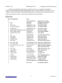
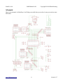
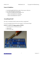
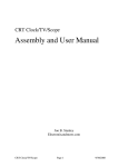
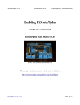
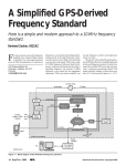
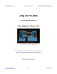
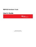
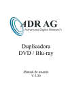
RoboPi v1.00
Build Manual 0.98
Copyright 2014 William Henning
Building RoboPi
Copyright 2014 William Henning
RoboPi build manual v0.98
Photo 1: Fully assembled RoboPi v1.00
The most up to date documentation will always be available at:
http://www.mikronauts.com/raspberry-pi/robopi/
http://Mikronauts.com
1
2014-01-27
RoboPi v1.00
Build Manual 0.98
Copyright 2014 William Henning
Table of Contents
Introduction................................................................................................................................................3
Parts List....................................................................................................................................................4
RoboPi Printed Circuit Board....................................................................................................................5
Schematic...................................................................................................................................................6
General Guidelines.....................................................................................................................................7
Assembling RoboPi....................................................................................................................................7
LM1117-3.3 SOT-23 Voltage regulator (VREG)..................................................................................7
6.250Mhz Crystal (Q1)..........................................................................................................................8
16 pin dip socket (MCP3008)...............................................................................................................9
40 pin dip socket (P8X32A-D40)..........................................................................................................9
8 pin dip socket (24LC256)...................................................................................................................9
Six 100nF ceramic 104 capacitors (C1-C4, C10, C11).........................................................................9
Two 470 ohm resistors (R29, R30).....................................................................................................10
Three 10k ohm resistors (R25, R26, R28)...........................................................................................10
Twenty-five 2.4k ohm resistors (R1 – R24, R27)................................................................................11
The diode (1N4004)............................................................................................................................11
Two 33uF electrolytic capacitors (C8, C9)..........................................................................................12
Two inductors (IND1, IND2)..............................................................................................................12
Two LED's (LED1, LED2)..................................................................................................................13
Two 1x3 male headers (SV3, SV3).....................................................................................................13
One 1x4 Male Prop-I2C header (PROP-I2C)......................................................................................14
One 1x4 Male Pi-I2C header (PI-I2C)................................................................................................14
Four 3x8 pin servo headers (SERVO1 & 9, SENSOR 1, ADC1).......................................................15
Three 1x10 female pin connectors (EXP1, EXP2, EXP3)..................................................................15
Trim 1x10F header pins on the bottom...............................................................................................15
Two screw terminal (X1).....................................................................................................................16
Two 47uF (or 100uF) electrolytic capacitors (C12, C13)...................................................................16
The 2x13 Stacking Pi header (SV1)....................................................................................................17
OPTIONAL: PropPlug header (PROPPLUG) (ONLY for stand-alone operation).............................18
Stand-Alone Operation............................................................................................................................18
Testing......................................................................................................................................................19
Programming RoboPi...............................................................................................................................20
RoboPi I/O pin definitions..................................................................................................................20
P0-P7: SERVO 1 – SERVO 8.........................................................................................................20
P8-P15: SERVO 9 – SERVO 16.....................................................................................................20
P16-P23: SENSOR 1 – SENSOR 9................................................................................................20
P24-P27: SPI port for MCP3008/MCP3208..................................................................................20
ADC1-ADC8: 0-5V Analog inputs................................................................................................20
RoboProp Software Compatibility:.....................................................................................................21
Appendix A: Required Tools....................................................................................................................22
Appendix B: Software..............................................................................................................................22
Appendix C: Data Sheets.........................................................................................................................22
Appendix D: Support...............................................................................................................................22
http://Mikronauts.com
2
2014-01-27
RoboPi v1.00
Build Manual 0.98
Copyright 2014 William Henning
Appendix E: Frequently Asked Questions...............................................................................................23
Introduction
RoboPi is the most advanced robot controller add-on board for the Raspberry Pi available at this time.
RoboPi adds an eight-core 32-bit microcontroller running at 100Mhz to the Raspberry Pi in order to
off-load hard real time I/O and allow more precise timing than Linux running on the Pi allows.
RoboPi stacked on top of a Model A
Raspberry Pi
RoboPi can also be stacked on top of
Model B Raspberry Pi's
RoboPi Features
•
•
•
•
•
•
•
•
•
•
•
•
•
Parallax Propeller P8X32 eight core 32 bit Risc microcontroller running at 100Mhz
Each of the eight cores provides up to 25MIPS as most instructions take only 4 clock cycles
three ten-pin Mikronauts I/O module expansion connectors (P0-P7, P8-P15, P16-P23)
24 servo compatible headers on P0..P23
◦ P0-P7 jumper selectable power from Pi's 5VDC supply or external servo power supply
◦ P8-P15 jumper selectable power from Pi's 5VDC supply or external servo power supply
◦ P16-P23 is powered by 5V from the Pi expansion header for sensors
Screw terminal for providing external power for Servo connectors P0-P15
8 servo compatible headers for an eight channel 0-5V analog to digital converter with choice of
◦ MCP3008 for 10 bit A/D conversion
◦ MCP3208 for 12 bit A/D conversion
Choice of 256Kbit or 512Kbit boot EEPROM for the Propeller
On-board voltage regulation providing 3.3V with power on LED from the 5V on the Pi header
4 pin I2C expansion header for the Raspberry Pi
4 pin I2C expansion header for the Propeller
5 pin HCOM connector for use with PropPlug in stand alone operation (optional)
Mikronauts EZasPi prototyping board can stack below RoboPi
Mikronauts Pi Jumper can stack on top of RoboPi
http://Mikronauts.com
3
2014-01-27
RoboPi v1.00
Build Manual 0.98
Copyright 2014 William Henning
• Mikronauts SchoolBoard ][ and other Propeller products are compatible with RoboPi
RoboPi is based on Mikronauts RoboProp advanced robot controller, and when configured to run at
100Mhz, with MCP3208 and 512Kb of EEPROM RoboPi can run RoboProp software that does not
require the L298 motor driver or microSD card reader present on RoboProp.
Parts List
Qty
1
1
1
2
2
1
4
3
2
1
1
1
1
2
25
3
6
2
2
2
1
2
1
1
1
1
2
2
PCB Marking
Part
MIKPCBROBOPI
SV1
MIKSTKPI
Q1
MIK6250
SV2, SV3
SAM1035-03-ND
PI-I2C, PROP-I2C
SAM1035-04-ND
PROPPLUG
SAM1035-05-ND
SERVO1&9, SENSOR1, ADC1 MIKSERVO8
EXP1, EXP2, EXP3
S7008-ND
install at SV2, SV3
3M9580-ND
X1
609-3936-ND
24LC256
A100204-ND
MCP3008
A100206-ND
P8X32A-D40
3M5471-ND
R29, R30
P470BACT-ND
R1 – R24, R27
CF18JT2K20CT-ND
R25, R26, R28
CF18JT10K0CT-ND
C1, C2, C3, C4, C10, C11
490-3811-ND
C8, C9
P951-ND
C12, C13
P5137-ND
IND1, IND2
811-2018-ND
RL205-TP
RL205-TPTR-ND
LED1, LED2
754-1200-ND
VREG
AZ1117CH-ND
Full Kit Only
24LC512-I/P-ND
Full Kit Only
MCP3208-CI/P-ND
Full Kit Only
P8X32A-D40-ND
M3 screw/spacer/nut
M3 spacer
http://Mikronauts.com
4
printed circuit board
2x13 stacking header
6.250Mhz crystal
1x3 male header
1x4 male header
1x5 male header
3x8 servo header
1x10 female header
2 pin shunt
2 screw terminal block
8 pin dip socket
16 pin dip socket
40 pin dip socket
470 ohm 1/4W resistor
2.4K ohm 1/4W resistor
10K ohm 1/4W resistor
100nF ceramic capacitor
33uF electrolytic cap
100uF electrolytic cap
1UH 3A inductor
2A diode
or equiv LED
3.3V voltage regulator
64KB EEPROM
12 bit 8 Ch ADC
Propeller MCU
mounting hardware
mounting hardware
2014-01-27
RoboPi v1.00
Build Manual 0.98
Copyright 2014 William Henning
RoboPi Printed Circuit Board
Here is a top view of where parts are located on the RoboPi printed circuit board:
You can refer to this image while building your board, as installing the parts will cover some of the silk
screened text indicating where the parts should be mounted.
Please see the RoboPi User Manual for user and programming instructions.
PLEASE NOTE
The “PROPPLUG” connection is for stand-alone RoboPi operation (where RoboPi is NOT stacked on
top of a Raspberry Pi.
Plugging in a PropPlug while RoboPi is stacked on the Raspberry Pi may damage your
Raspberry Pi and/or RoboPi.
http://Mikronauts.com
5
2014-01-27
RoboPi v1.00
Build Manual 0.98
Copyright 2014 William Henning
Schematic
Here is the schematic for RoboProp. It will help you trouble shoot your robot in case you run into some
difficulties.
http://Mikronauts.com
6
2014-01-27
RoboPi v1.00
Build Manual 0.98
Copyright 2014 William Henning
General Guidelines
•
•
•
You should assemble RoboPi in the order of shortest part to tallest part
Use a clean soldering iron with a good tip
after you have assembled the board, make sure that
◦ there is no short between 5V and GND
◦ there is no short between 3.3V and GND
◦ there is no short between 5V and 3.3V
Assembling RoboPi
The order you assemble the board in matters more than you might think!
If you do not assemble the board in the correct sequence, it will take much longer.
LM1117-3.3 SOT-23 Voltage regulator (VREG)
•
•
•
use locking tweezers to hold the part in place
soldter top tab
solder the three legs
http://Mikronauts.com
7
2014-01-27
RoboPi v1.00
Build Manual 0.98
Copyright 2014 William Henning
6.250Mhz Crystal (Q1)
If your 40 pin socket looks like an empty rectangle, mount the crystal on the top as shown above.
If your 40 pin socket has a central bar, you should mount the crystal on the bottom of the board.
Here you can see the two 40 pin socket types, and how to mount the crystal for each type, side by side:
Please mount the IC sockets in the order of shortest to tallest (with respect to the PCB)
http://Mikronauts.com
8
2014-01-27
RoboPi v1.00
Build Manual 0.98
Copyright 2014 William Henning
16 pin dip socket (MCP3008)
•
•
•
mount the 16 pin IC socket, note half-circle orientation indicator on socket and PCB
make sure the socket sits evenly and is flush to the RoboPi board
solder it on the bottom of the board
40 pin dip socket (P8X32A-D40)
•
•
•
mount the 40 pin IC socket, note half-circle orientation indicator on socket and PCB
make sure the socket sits evenly and is flush to the RoboPi board
solder it on the bottom of the board
8 pin dip socket (24LC256)
•
•
•
mount the 8 pin IC socket, note half-circle orientation indicator on socket and PCB
make sure the socket sits evenly and is flush to the RoboPi board
solder it on the bottom of the board
Six 100nF ceramic 104 capacitors (C1-C4, C10, C11)
http://Mikronauts.com
9
2014-01-27
RoboPi v1.00
Build Manual 0.98
Copyright 2014 William Henning
Two 470 ohm resistors (R29, R30)
Three 10k ohm resistors (R25, R26, R28)
http://Mikronauts.com
10
2014-01-27
RoboPi v1.00
Build Manual 0.98
Copyright 2014 William Henning
Twenty-five 2.4k ohm resistors (R1 – R24, R27)
The diode (1N4004)
Please note – the kit now supplies a 2A RL205-TP diode; please note how the silver stripe on the diode
is right above the white stripe on the printed circuit board silk screen – it indicates polarity.
http://Mikronauts.com
11
2014-01-27
RoboPi v1.00
Build Manual 0.98
Copyright 2014 William Henning
Two 33uF electrolytic capacitors (C8, C9)
The electrolytic capacitors are polarized, so make sure you put the longer lead (positive) in the hole
with the “+” sign.
Two inductors (IND1, IND2)
http://Mikronauts.com
12
2014-01-27
RoboPi v1.00
Build Manual 0.98
Copyright 2014 William Henning
Two LED's (LED1, LED2)
Both LED's anodes (longer legs) go into the holes closer to the “RoboPi” text on the top of the board.
Two 1x3 male headers (SV3, SV3)
http://Mikronauts.com
13
2014-01-27
RoboPi v1.00
Build Manual 0.98
Copyright 2014 William Henning
One 1x4 Male Prop-I2C header (PROP-I2C)
One 1x4 Male Pi-I2C header (PI-I2C)
http://Mikronauts.com
14
2014-01-27
RoboPi v1.00
Build Manual 0.98
Copyright 2014 William Henning
Four 3x8 pin servo headers (SERVO1 & 9, SENSOR 1, ADC1)
Three 1x10 female pin connectors (EXP1, EXP2, EXP3)
Trim 1x10F header pins on the bottom
http://Mikronauts.com
15
2014-01-27
RoboPi v1.00
Build Manual 0.98
Copyright 2014 William Henning
Two screw terminal (X1)
Two 47uF (or 100uF) electrolytic capacitors (C12, C13)
See C12 & C13 positions above – note the small “+” sign indicating which lead is positive.
The electrolytic capacitors are polarized, so make sure you put the longer lead (positive) in the hole
with the “+” sign.
http://Mikronauts.com
16
2014-01-27
RoboPi v1.00
Build Manual 0.98
Copyright 2014 William Henning
The 2x13 Stacking Pi header (SV1)
NOTE: The legs of the header MUST be on the top (component) side, the female (socket) part on
the bottom – look at the following two phots carefully!
You can see how to place the Pi 2x13 stacking header in these photos.
http://Mikronauts.com
17
2014-01-27
RoboPi v1.00
Build Manual 0.98
Copyright 2014 William Henning
OPTIONAL: PropPlug header (PROPPLUG) (ONLY for stand-alone operation)
•
Pins 1-4 are identical to the Parallax PropPlug connector
•
Pin 1 is Vss, pin 5 is 3v3
•
DO NOT mount this header if you will only use RoboPi on a Raspberry Pi
•
DO NOT plug in a PropPlug when RoboPi is mounted on a Raspberry Pi
Stand-Alone Operation
Supply 5V to RoboPi via one of:
•
pins 2 & 4 of the 2x13 pin Pi Header
•
“Pi5V” terminal of power selection header SV2 or SV3
Supply GND to RoboPi via one of:
•
pins 9 & 14 of the Pi Header
•
GND terminal of the external motor power screw terminal
If you will never mount your RoboPi on a Raspbery Pi, you could mount a two pin screw terminal on
pins 2 (5V) & 6 (GND) for supplying 5V.
Use a PropPlug to program your stand-alone RoboPi.
http://Mikronauts.com
18
2014-01-27
RoboPi v1.00
Build Manual 0.98
Copyright 2014 William Henning
Testing
•
test for short between 5V and GND on Pi header
•
test for short between 3v3 from vreg and GND
•
test for short between 3v3 from vreg and 5V from Pi
•
test for short between 5V from Pi and Vbat
•
test for short between pins 1&2 of the PropPlug connector
•
test for short between pins 3&4 of the PropPlug connector
If you have a multi-meter, check for shorts between 5V/GND, 3v3/GND, 5v/3v3 on the Pi header don't worry about a high resistance (capacitors) but anything less than say 4k may indicate a problem.
Also check for a short between Pin 1 & Pin 4 of the two I2C connectors, as any short at the voltage
regulation would show up there.
You can find a nice diagram, and listing, of the pins on the Raspberry Pi header at:
http://elinux.org/RPi_Low-level_peripherals
http://Mikronauts.com
19
2014-01-27
RoboPi v1.00
Build Manual 0.98
Copyright 2014 William Henning
Programming RoboPi
RoboPi I/O pin definitions
P0-P7: SERVO 1 – SERVO 8
•
•
•
10 pin EXP1 connector connected directly to processor pins, 3v3 I/O only
connects to signal pin on SERVO1-8 through a 2k4 current limiting resistor, 5V I/O safe
For the servo header, SV2 selects between the Pi's 5V and VBat from the screw terminal
P8-P15: SERVO 9 – SERVO 16
•
•
•
10 pin EXP2 connector connected directly to processor pins, 3v3 I/O only
connects to signal pin on SERVO9-16 through a 2k4 current limiting resistor, 5V I/O safe
For the servo header, SV3 selects between the Pi's 5V and VBat from the screw terminal
P16-P23: SENSOR 1 – SENSOR 9
•
•
•
10 pin EXP3 connector connected directly to processor pins, 3v3 I/O only
connects to signal pin on SENSOR1-8 through a 2k4 current limiting resistor, 5V I/O safe
the Pi's 5V is used for SENSOR1-8 to provide cleaner power to Ping's etc
P24-P27: SPI port for MCP3008/MCP3208
•
•
•
•
P24 is MISO, connected to DO on ADC through a 2k4 current limiting resistor
P25 is MOSI
P26 is CLK
P27 is /CS
ADC1-ADC8: 0-5V Analog inputs
•
•
connects to the signal pin on ADC1-8 servo style header
the Pi's 5V is used for ADC1-8 to provide cleaner power to Ping's etc
http://Mikronauts.com
20
2014-01-27
RoboPi v1.00
Build Manual 0.98
Copyright 2014 William Henning
RoboProp Software Compatibility:
•
•
•
use the supplied 6.250Mhz crystal for 100Mhz operation
use 24LC512 EEPROM
use MCP3208
While there is no motor driver on RoboPi, if you connect a two channel motor controller as follows it
will be RoboProp compatible:
•
•
•
•
•
Tie EN1-2 and EN3-4 high
P8 to IN1
P9 to IN2
P10 to IN3
P11 to IN4
If you want to have a uSD card compatible with RoboProp, attach it as follows:
•
•
•
•
P12 to MISO
P13 to MOSI
P14 to CLK
P15 to /CS
http://Mikronauts.com
21
2014-01-27
RoboPi v1.00
Build Manual 0.98
Copyright 2014 William Henning
Appendix A: Required Tools
•
•
•
•
25W-40W fine tip soldering iron or temperature controlled soldering station
wire snippers
phillips screw driver
pliers
Appendix B: Software
•
•
•
•
•
Raspbian Wheezy or later
SimpleIDE 0.8.4 or later
propeller-load3 or later
RoboPi API v1.0 or later
RoboPiLib v1.0 or later
Appendix C: Data Sheets
http://www.parallax.com/sites/default/files/downloads/P8X32A-Propeller-Datasheet-v1.4.0_0.pdf
http://www.parallax.com/sites/default/files/downloads/P8X32A-Web-PropellerManual-v1.2.pdf
http://ww1.microchip.com/downloads/en/DeviceDoc/21298c.pdf
http://ww1.microchip.com/downloads/en/DeviceDoc/21754M.pdf
You can find the data sheets for the listed Digikey part numbers at Digikey.com by typing in the part
number and clicking on the pdf icon on the resulting page.
Appendix D: Support
For Raspberry Pi support, including Raspbian, please see the Raspberry Pi forums at:
http://www.raspberrypi.org/forum/
For Parallax Propeller support, see the Parallax forum at:
http://forums.parallax.com/forumdisplay.php/65-Propeller-1-Multicore-Microcontroller
For RoboPi support, please visit the RoboPi thread in the Propeller forum at:
http://forums.parallax.com/showthread.php/153275-Propeller-add-on-for-Raspberry-Pi-RoboPi..-the-m
ost-advanced-robot-controller-for-Pi
http://Mikronauts.com
22
2014-01-27
RoboPi v1.00
Build Manual 0.98
Copyright 2014 William Henning
Appendix E: Frequently Asked Questions
Q: Where can we buy RoboPi?
A: Currently you can buy RoboPi:
Directly from us – please email us at [email protected] with desired quantity and postal
address, we will be happy to send you a quote. We accept PayPal from verified buyers.
From our Ebay store – please visit us at out Mikronauts Ebay store!
<add actual URL>
Distributors and dealers are welcome to contact us for quantity discounts – we would love to have you
on-board!
Q: Are quantity and educational discounts available for RoboPi?
A: Yes! We are happy to offer quantity based discounts to our educational users and distributors.
Please contact us for a custom quote.
Q: Can we make our own RoboPi printed circuit boards?
A: I am afraid not. While RoboPi is an open platform in that it is fully documented, with source code
available for its libraries and demo applications, RoboPi is a commercial product, and may not be
copied.
Q: Can we use the less expensive MCP3008 10 bit analog to digical converter instead of the
MCP3208?
A: Yes, you can – but the driver needs to be modified, and the RoboPi libraries and demonstration
programs assume that an MCP3208 is used. We intend to offer a merged MCP3208/MCP3008 driver
soon which will allow a common code base.
Q: Do you have any distributors in <name of country>?
A: We are working hard to set up our distribution network. Please email your favorite web stores and
have them contact us if they are interested in RoboPi.
http://Mikronauts.com
23
2014-01-27