1
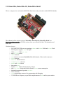
DuinoMite User's Manual
Revision 1.03 December 2011
Copyright 2011, Olimex Ltd (Based on original Maximite by Geoff Graham www.geoffg.net)
Released under Creative Commons Attribution Share Alike 3.0 United States Licensee
1. INTRODUCTION
DuinoMite is a series of compact development boards based on the PIC32 microcontroller from
Microchip Technology Inc.
The DuinoMite is a complete computer, running a BASIC interpreter called MM-Basic (originally
written by Geoff Graham), which when interfaced with a PS2 keyboard and VGA monitor, is
reminiscent of the old retro APPLE][ and TRS-80 personal computers. No need for a PC, no need for
compilers IDEs, programmers, all you need to write embedded applications is DuinoMite.
DuinoMites have ARDUINO shield connectivity, allowing ARDUINO shields to be directly interfaced,
making the DuinoMite the world's first stand alone ARDUINO Single Board Complete BASIC
computer .
DuinoMite is a completely open source platform and the schematic and board files are available for
download from the Olimex (www.olimex.com) web site and released under the Creative Commons
Attribution-Share Alike 3.0 United States License, which generally means that you are free to use these files
to create your own product providing you credit Olimex as the source and release your files with the
same license as well.
The heart of DuinoMite is the PIC32MX795F512 which, amongst others, includes the following
features: On-Chip: 80Mhz clock operation, 512KB Flash memory, 128KB RAM memory, USB with
OTG functionality, UARTs, SPIs, I2C, ADC, CAN, PMP.
Three DuinoMite boards are in production:
DuinoMite-Mega
http://www.olimex.com/dev/DUINO/duinomite-mega.hrml
DuinoMite-Mini
http://www.olimex.com/dev/DUINO/duinomite-mini.hrml
DuinoMite
http://www.olimex.com/dev/DUINO/duinomite.hrml
and two more boards are in design phase at the current date:
DuinoMite-eMega board with Ethernet, Internal Flash and PMP, with possibility for color VGA output.
PIC32-T795 which is a low cost, general purpose, development board for easy bread-boarding using
wire jumpers.
2. BOARDS
2.1. DuinoMite-Mega
This is, to date, the most sophisticated board from DuinoMite range of boards.
The schematic of the current revision of the DuinoMite-Mega can be found online in the DUINO
section at http://www.olimex.com/dev, you will also find the CAD schematics and board files.
DuinoMite-Mega is available for sale as either a pre-assembled board only or alternatively, in a laser
cut, custom made plastic enclosure:
Hardware features:
–
–
–
–
–
–
–
–
–
–
–
–
–
–
–
–
–
–
–
–
–
–
PIC32MX795F512H processor running at 80Mhz with 128KB RAM and 512KB Flash
DC-DC power supply 9-30V DC input
USB Device / USB Host OTG
mini SD card socket
two UEXT connectors, one inside enclosure, one outside
CAN connector
GPIO connector
ARDUINO shield connector
PS2 Keyboard connector
RS232 connector
VGA connector
Audio RCA jack
Composite Video RCA jack
Headphones 3.5 mm jack
RESET and USER buttons
three status LEDs
build-in LiPo Lithium-Polimer battery charger
ultra low power design which allow down to 30uA current consumption
Industrial temperature operation -40+85C
Noise immunity
ICSP programming connector for programming and debugging
32,768 KHz low frequency crystal allow implementation of RTC and low power modes
2.2. DuinoMite-Mini
This is the compact, low cost, entry level board with size of only 65 mm x 50 mm.
The schematic of the current revision of DuinoMite-Mini is at http://www.olimex.com/dev in the
DUINO section, where you can also find the CAD schematic and board files.
Hardware features:
– PIC32MX795F512H processor running at 80Mhz with 128KB RAM and 512KB Flash
– Linear power regulator, require EXACTLY 5V to the DC POWER JACK
– USB Device DuinoMite-Mini can take power from USB also, there is 3 way jumper
which selects which source is used the DC POWER JACK or the USB
– mini SD card socket
– UEXT connector
– GPIO connector
– PS2 Keyboard connector
– VGA connector
– RESET button
– USER buttons
– three status LEDs
– Commercial temperature operation -0+70C
– Noise immunity
– ICSP programming connector for programming and debugging
– 32,768 KHz low frequency crystal allow implementation of RTC and low power modes
2.3. DuinoMite, DuinoMite-IO, DuinoMite-Shield
This is a compact, low cost board in ARDUINO form factor ready to interface with ARDUINO shields.
The schematic of the current revision of DuinoMite, DuinoMite-IO, DuinoMite-Shield is at
http://www.olimex.com/dev in DUINO section, where you will also find the CAD schematics and
board files.
Hardware features:
–
–
–
–
–
–
–
–
–
–
–
–
–
–
–
–
–
PIC32MX795F512H processor running at 80Mhz with 128KB RAM and 512KB Flash
DC-DC power supply 9-30V DC input
USB Device / USB Host OTG
mini SD card socket
UEXT connector
EXT connector to connect DuinoMite-IO with Keyboard, Video, Audio connectors
GPIO connector
ARDUINO shield connector
DUINOMITE-IO connector
RESET and USER buttons
three status LEDs
build-in LiPo Lithium-Polimer battery charger
ultra low power design which allow down to 30uA current consumption
Industrial temperature operation -40+85C
Noise immunity
ICSP programming connector for programming and debugging
32,768 KHz low frequency crystal allow implementation of RTC and low power modes
2.4. DuinoMite-eMega
This is a new Ethernet enabled board, still in development. The features will be similar to the
DuinoMite-Mega, but with some additional features such as Ethernet connector and PHY controller,
which will add a 100Mbit Ethernet interface to DuinoMite, 2MB on board Data Flash which could be
used as disk for data and code storage. PMP external connector with 80Mhz clock which could be used
to interface to TFT displays, fast ADCs, allowing Duinomite to be used as Logic Analyzer, Digital
Storage oscilloscope, capture for fast external signals.
2.3. PIC32-T795 (breadboarding PIC32MX795)
This is a new breadboard based on Ken Segler's design. It is T-shaped and is intended to plug into a
breadboard. It incorporates a UEXT connector and USB with Device and Host (OTG)
PIC32-T795 is the fastest way to make something with a breadboard and Jumper wires without the
need to solder.
PIC32-T795 can be reused many times as no soldering is required.
3. HARDWARE
3.1. POWER Supply
3.1.1. DuinoMite-Mega
DuinoMite-Mega can be powered by four different sources:
- POWER JACK with a 2.1 mm internal pin and 6 mm outer diameter, the inner pin is positive,
the voltage that the DuinoMite-Mega accepts on this connector is in range 9-30V DC, note that there
is a DC / DC power supply implemented, so the power consumption of this board is the same no matter
what the input voltage is, other similar boards we have seen use linear voltage regulators heat up when
a higher voltage is applied and wastes energy. There is a reverse voltage protection diode on this
connector, to protect against reverse polarity.
- USB power supply, when DuinoMite-Mega is connected via a USB cable to a USB host it will
take its 5V power supply from the USB host source to power the board, note that depending on what
frequency the DuinoMite-Mega runs at, it may consume up to 140mA, so the USB port needs to be able
to provide this current, some USB ports are set to 100mA maximum current supply and may be not able
to power the DuinoMite-Mega.
- Lithium-Polimer battery, DuinoMite-Mega hardware is build to be very power efficient. In
Low Power mode DuinoMite-Mega consumes only 30uA (plus current draw from the I/O pins) while
the RTC low frequency clock is running, so this allows handheld and battery powered devices to be
built with the DuinoMite.
- VIN port on the Arduino platform Connector 1. Note that on this connector there is NO reverse
protection diode, so you should make sure 9-30V DC is applied to this port.
DuinoMite-Mega could be powered by more than one power source at the same time, for instance
POWER JACK and USB at same time. The different power sources have different priorities, this
means when two or more power sources are available at the same time only one of them is used.
The priority is the POWER JACK and VIN, if the power supply is applied to any of these two
connectors, the power is sourced from them and not from the USB and/or the battery, second priority is
USB, if there is no power applied to POWER JACK or VIN and USB is active then the power will be
taken from the USB. The battery power supply is with lowest priority and board will take power from it
only if there is no power supply to any of the other sources.
DuinoMite-Mega has a built in LiPo battery charger, so once it senses power on POWER JACK, USB
or VIN it will charge the LiPo battery (If present) until the battery is charged to 100%.
The switching between the different power supplies is done automatically and glitch free with no need
to change jumpers. Board power is not lost during voltage source switching.
The LiPo battery with 3.7V 1400mA capacity and JST connector for DuinoMite-Mega is available
from Olimex. At maximum frequency with a VGA monitor connected the consumption is 125mA which
will allow the DuinoMite-Mega to run about 10 hours on battery.
As the external power supply utilises a DC/DC converter and not a linear voltage regulator the
DuinoMite-Mega power consumption when running at maximum frequency and with a VGA monitor
and keyboard attached is 100mA when the input power supply is 12VDC. (at 30VDC the current will
drop to 40mA and will rise to 130mA at 9VDC).
3.1.2. DuinoMite-Mini
The DuinoMite-Mini power supply is made with a linear voltage regulator to save cost (an LM1117 is
used). The power source could be USB connector or POWER JACK. The source is selected with a 3way jumper. The board has a protection ZENER diode (6.8V) on the input to protect the board from
over-voltage spikes on the power supply.
Note
The external power supply applied to the POWER JACK must be 5V REGULATED. Note that applying
non-regulated or voltage above 5V could DESTROY the DuinoMite-Mini.
Our recommendation is to use USB to power this board or the cheap `under $2' power supply adapters
for iPods, iPads, e-readers etc. which are with specification 5V/1A and are available on eBay.
3.1.3. DuinoMite
The DuinoMite has same sophisticated power supply like DuinoMite-Mega and allows power supply
9-30VDC.
3.2. USB
The PIC32MX795 has a USB controller which can work in two modes:
- USB device, in this mode you can make USB HID devices or USB CDC devices and emulate
such devices like Keyboard, Mouse, Serial port etc., this mode is supported by all DuinoMite boards.
- USB On-The-Go (OTG) host/device mode in which the USB host PIC32 can interface USB
mouse, USB keyboard, USB camera, USB printers, USB Bluetooth, WiFi modules, USB memory stick
etc. Of course all of these devices need proper drivers to be implemented. This mode is not yet
supported by DuinoMite-Mini board.
Special care is taken in the DuinoMite design for USB noise immunity and protection when it works in
host mode.
When working as USB host DuinoMite may provide up to 500mA to the USB devices attached, so this
should be taken into account when you size the power supply input voltage/current.
MM-BASIC uses USB as an HID device during boot-loading when new firmware is updating, then as a
CDC serial port to establish a virtual console from which you can write your MM-BASIC code via a
terminal program with a USB connection, thus there is no need to use a VGA monitor or PS2
Keyboard.
USB-FAULT signal is low when there is no power supplied to either the USB or the POWER JACK. It
is connected to port RG7 and could be used to detect when you are powered only on battery.
3.3. SD-CARD
A micro SD card connector is available on DuinoMite-Mega, DuinoMite-Mini, DuinoMite-eMega and
DuinoMite boards, this connector is with push-push action to insert and remove the card.
The uSD power supply is designed with ferrite bead filtering to minimise noise problems.
As DuinoMite, and DuinoMite-Mega are designed to be low power boards there is provision for the
SD-card power supply to be shut down, this is done with FET2 connected to STB_E on RB13 port of
PIC32.
SD-CARD presence is sensed by the SD_#CS connected to RD5 port, there is low pull down made
with 100K on this port so when there is no card inserted RD5 is read as 0, when SD card is inserted it
have 10K pullup inside which pull RD5 high and it's read as 1.
Note that the SPI used for the SD card is also wired to UEXT and ARDUINO connectors, so
programmer should take care of this when writing their code.
3.4. UEXT
The UEXT connector is a 10 pin connector which have the following signals: 3.3V power supply,
GND, Serial RX, Serial TX, SPI MOSI, SPI MISO, SPI CLK, I2C CLK, I2C DATA.
By having these signals available on a fixed interface allows us to develop different modules which can
be used on any board with a UEXT connector.
All DuinoMite boards have UEXT connectors and can interface Olimex's UEXT modules.
For more information on UEXT see: http://www.olimex.com/dev/OTHER/UEXT.pdf
Please look at the example section of this manual for sample MM-BASIC code for various modules.
The DuinoMite-Mega has two UEXT connectors one internal and one external.
3.5. ARDUINO SHIELDS
ARDUINO is popular platform for development by beginners and people with little knowledge in
electronics. This platform is gaining popularity and there are lot of projects using it. Arduino allows
various hardware modules to be stacked on top of each other. They are called SHIELDS.
DuinoMite and DuinoMite-Mega have this connector to allow ARDUINO SHIELDS to be connected.
This connector is also very useful for jumper wiring to an external breadboard.
The DuinoMite-Mini has no ARDUINO shield connector on board but has the 26pin GPIO connector
which can be connected to an external DuinoMite-Shield board, which adds the ARDUINO SHIELD,
connected via a 26 pin ribbon cable.
The ARDUINO SHIELD has these signals:
D0,D1,D2,D3,D4,D5,D6,D7,D8,D9,D10,D11,D12,D13,
AREF, A0,A1,A2,A3,A4,A5
VIN, GND, 5V, 3.3V, RST, CTS, RTS
D0 – D13 are digital I/Os,
A0-A5 are analog I/Os,
VIN – input power which allows you to power DuinoMite (or Mega) by an external power supply
RST – reset
CTS, RTS – handshake signals from the Mega's RS232 connector, they are TTL levels.
MM-BASIC can access ARDUINIO SHIELDS with the PIN() function.
These ports may be digital inputs, digital outputs and analog inputs, note max voltage to these ports
should not exceed 3.3V as they may be damaged:
ARDUINO.A0
ARDUINO.A1
ARDUINO.A2
ARDUINO.A3
ARDUINO.A4
ARDUINO.A5
→
→
→
→
→
→
PIN(1)
PIN(2)
PIN(3)
PIN(4)
PIN(5)
PIN(6)
These ports may be digital inputs, digital outputs, they are 5V tolerant, so the maximum input voltage
which you should apply to them should not exceed 5V.
ARDUINO.D0
ARDUINO.D1
ARDUINO.D2
ARDUINO.D3
ARDUINO.D4
ARDUINO.D5
ARDUINO.D6
ARDUINO.D7
→
→
→
→
→
→
→
→
PIN(11)
PIN(12)
PIN(13)
PIN(14)
PIN(15)
PIN(16)
PIN(17)
PIN(18)
→
→
→
→
→
→
COM1:RX →
COM1:TX →
COM1:RTS
COM1:CTS
COM2:RX
COM2:TX
COM4:RX from RS232 connector
COM4:TX from RS232 connector
NOTES!
D0 & D1 are wired via protection resistors to the RS232 connector (COM4) on the DuinoMite-Mega
this means that if there are signals on the RS232 connector they will affect D0, if D1 is initialized as
INPUT this signal will merge with the signal on ARDUINO.D0 connector. Also if D1 is initialized as
output it will affect COM4 port transmission. If you want to separate COM4 from D0 and D1 you can
do this by removing R2 and R3.
As COM1: TX, RX are available on same D0 D1 ports anyway, R2 and R3 may be removed unless you
need a fast UART there.
These ports share more than one function together and should be used with care:
ARDUINO.D8
ARDUINO.D9
ARDUINO.D10
ARDUINO.D11
ARDUINO.D12
ARDUINO.D13
→
→
→
→
→
→
PIN(19)
PIN(20)
PIN(7)
PIN(8)
PIN(9)
PIN(10)
→
→
→
→
→
→
UEXT.CS/VIDEO.SELECT
LED2(YELLOW) VGA.SYNC
UEXT/SD.CARD.SS
UEXT/SD.CARD.MOSI
UEXT/SD.CARD.MISO
UEXT/SD.CARD.CLK
NOTES!!
If you use UEXT.SPI or SD-CARD note that the SPI signals also go to ARDUINO.D10-D13.
ARDUINO.D8 is shared with VIDEO.SELECT and UEXT.CS
3.6. CAN
Controller Area Network (CAN or CAN-bus) is a bus standard, generally used in the automotive
industry, designed to allow micro-controllers and devices to communicate with each other within a
vehicle, and without a host computer.
CAN is available only on the DuinoMite-Mega.
CAN is a very useful interface, it’s the de-facto standard for automotive bus applications, so by having
CAN it would be possible to connect to your car and read all of the data sensors for speed,
temperatures, fuel consumption, etc. This video can give you rough idea what you can do with CAN
and DuinoMite-Mega. http://www.youtube.com/watch?v=PbA_bOO2mMw
Being a robust and noise immune protocol, CAN is used not only in automotive but also in industrial
robot applications – For more information see the following links
http://en.wikipedia.org/wiki/DeviceNet
http://en.wikipedia.org/wiki/CANopen
CAN is not supported currently in MM-BASIC, but in a future firmware CAN will be implemented to
be seen as a file, the same as the COM ports, so you will be able to do OPEN “CAN” AS #1 and use
INPUT # , INPUT$ and PRINT # to send and receive CAN messages.
The CAN connector consists of these 3 signals:
CAN-H, CAN-L – these are the CAN physical layer twisted pair
GND - the shielding connection
The CAN end node should have termination resistor and if CAN-T is soldered (shorted) add such
termination resistor to the CAN bus.
3.7. GPIO
The original MaxiMite introduced the 26 pin GPIO connector. With the emergence of the DuinoMite
and support for ARDUINO we expanded the GPIO layout as shown below:
MM-BASIC allows the GPIO ports to be accessed with the PIN() command and function, and different
functions to be set with SETPIN command.
SETPIN configurations:
0
- not defined
1
- analog input AI
2
- digital input DI
3
- frequency input FI
4
5
6
7
8
9
MMBasic
Referrence:
- period input PI
- counter input CI
- interrupt low-to-high IP
- interrupt high-to-low IN
- digital output DO
- digital output open collector OC
Arduino
26pin header
Referrence
Pin No.
PIN(1) →
PIN(2) →
PIN(3) →
PIN(4) →
PIN(5) →
PIN(6) →
PIN(7) →
PIN(8) →
PIN(9) →
PIN(10)→
PIN(11)→
PIN(12)→
PIN(13)→
PIN(14)→
PIN(15)→
PIN(16)→
PIN(17)→
PIN(18)→
PIN(19)→
PIN(20)→
GND→
+5V→
+3.3V →
ARDUINO.A0
ARDUINO.A1
ARDUINO.A2
ARDUINO.A3
ARDUINO.A4
ARDUINO.A5
ARDUINO.D10
ARDUINO.D11
ARDUINO.D12
ARDUINO.D13
ARDUINO.D0
ARDUINO.D1
ARDUINO.D2
ARDUINO.D3
ARDUINO.D4
ARDUINO.D5
ARDUINO.D6
ARDUINO.D7
ARDUINO.D8
ARDUINO.D9
GND (x3)
+5v (1)
+3.3v (1)
Allowable SETPIN
Configurations
21 AI, DI, , , , IP, IN, DO,
19 AI, DI, , , , IP, IN, DO,
17 AI, DI, , , , , , DO,
15 AI, DI, , , , , , DO,
13 AI, DI, FI, PI, CI, IP, IN, DO,
11 AI, DI, FI, PI, CI, IP, IN, DO,
9
AI, DI, FI, PI, CI, IP, IN, DO,
7
, DI, , , , , , DO, OC
5
, DI, , , , , , DO, OC
3
, DI, , , , , , DO, OC
4
, DI, , , , , , DO,
6
, DI, , , , , , DO,
8
, DI, , , , , , DO, OC
10
, DI, , , , , , DO, OC
12
, DI, , , , , , DO, OC
14
, DI, , , , , , DO, OC
16
, DI, , , , , , DO, OC
18
, DI, , , , , , DO, OC
20
AI, DI, , , , , , DO,
22
AI, DI, , , , , , DO,
1,2,25,26
23
24
NOTE!!
The PIN(7), PIN(8), PIN(9), PIN(10) are marked with blue as they are multiplexed with SPI which is
used for UEXT and SD-card, this means that if UEXT or SD-card is accessed these lines will change
their states. Please do not use or use with care if you use also UEXT and SD-card operations in your
code.
PIN(19), PIN(20) are marked with blue as they are multiplexed with VGA.VSYNC and VGA.VIDEODETECT. Please do not use or use with care if you use also VGA monitor.
3.8. PS-2 KEYBOARD
PS2 keyboard CLOCK is connected to RD6 and DATA is connected to RD7.
Note that the Keyboard requires 5V to work correctly, so the keyboard will not work when the
DuinoMite-Mega is powered by 3.7V LiPo battery.
3.9. VGA / Video
The VGA monitor is uses the PIC32 SPI to generate the video signal.
VGA.HSYNC is generated by RD4, VGA.VSYNC is generated by RB12 which is also connected to
LED2 (YELLOW) and ARDUINO.D9.
VGA R/G/B signals are connected together via small SMD jumpers if you selectively cut them you can
make your Video output RED, GREEN, BLUE, AMBER or YELLOW in color.
PIC32 RG8, RG9 generates the Video signal.
Composite video signal is also generated if VGA monitor is not detected. The composite video is
output to the VIDEO RCA connector. PAL, SECAM, NTSC modes are supported, note that in
Composite Video mode the screen resolution is lower than VGA mode.
3.10. AUDIO
The DuinoMite has two connectors, an AUDIO RCA jack connector and a 3.5mm headphone
connector. MM-BASIC can output to these connectors with the SOUND command, with frequencies
up to 1Mhz, and by using the duty cycle parameter, PWM will be available from these connectors.
3.11. LEDS
The DuinoMite has three LEDs:
–RED power supply LED, is ON when the board is powered by external power supply or USB,
and is OFF if the power supply is the LiPo battery.
–YELLOW is the system RUN status, if this LED is ON, VGA video is generated correctly and
the board is ready to work.
–GREEN this is SD card activity LED and is ON when SD-card is accessed. PIN(0) will also drive
this LED on and off.
3.12. BUTTONS
The DuinoMite has two buttons: RESET and USER BUTTON.
RESET button does a hardware reset (hot start) and all code in memory is cleared and board initialized
as if it was just powered up.
The Duinomite has a boot-loader which allows the firmware to be upgraded without need of an
external programmer. To enter the boot-loader the USER button should be pressed at power-up or
RESET. To enter the boot-loader press and hold USER button, then press and release RESET button.
When you release the USER button the YELLOW and GREEN LEDs will blink alternately to show
that the board is in boot-loading mode. To load the new firmware run the Bootloader.exe and select the
new HEX code.
The USER button status can also be read with the PIN(0) function.
3.13. BATTERY
The DuinoMite and DuinoMite-Mega have a built-in LiPo battery charger and the hardware is
designed to allow them to run in low power mode for battery operation.
USB-FAULT is connected to RG7 to allow the firmware to be aware that it is running on battery
instead of an external power supply. If USB-FAULT is read as 0 the board is powered by battery.
The battery charge state can be monitored by measuring the power supply on BAT port RB2.
The Lithium Polimer battery is connected via the R31/R29 voltage divider (0.319727891) to RB2 port
as RB2 can handle a maximum voltage of 3.3V but the battery voltage can go up to 4.2V when
completely charged.
DM firmware adds PIN(21) analog input pin which could be used for Battery voltage monitoring. Note
that voltage is sensed through voltage vivider as PIC32 inputs can't measure more than 3.3V while LiPo battery voltage may go up to 4.2V when completely loaded. This is why the measured values from
PIN(21) should be multiplied by the magic number 3.13 to get the real battery voltage.
3.14. HARDWARE SIGNATURE
The DuinoMite hardware signature allows the firmware to be aware of which board it is running. This
is very useful for the boot-loader to determine which firmware to download to it. The signature is done
by a voltage divider made from R40/R30 read on RB14 initialized as analog input. For the current
revision of the hardware the voltage divider is 1:10 so if 0.33V is read on this port your code runs on
the DuinoMite hardware.
4. SOFTWARE
4.1. DIRECT PROGRAMMING USING MPLAB, C32, PIC-KIT3
By programming in C you will have access to all processor resources.
What you will need is:
–Obtain MPLAB-X and the C32 compiler from Microchip ( http://www.microchip.com) and
download the latest DuinoMite firmware from Olimex ( http://www.olimex.com)
–we assume you already have a PIC32 programmer/debugger, if you do not have you may need
to obtain the PIC-KIT3 and PIC-ICSP, note that you will need the PIC-ICSP even if you have
the Microchip programmer as DuinoMite uses a small 0.05” ICSP connector instead of the
more common 0.10" ICSP connector.
With this setup you have access to a complete development environment which works on Windows,
Linux, MAC OS and you can use all of the hardware features of DuinoMite boards.
4.2. PINGUINO IDE
The Pinguino Project is a complete integrated IDE and C compiler. It works with the boot-loader so
there is no need for programmers etc. when you program using the Pinguino IDE. The project page is at
http://www.pinguino.cc
Pinguino implements the ARDUINO like language which is generally C++ libraries to allow easy
programming of the hardware.
The DuinoMite boards are based on our PIC32-PINGUINO-OTG project hardware and evolved from
there, so they can use the existing Pinguino programming environment, the only difference is that a
different boot-loader should be programmed into the DuinoMite to support Pinguino IDE.
The Pinguino IDE allows you to program the DuinoMite in ARDUINO language or pure C/C++ and
load the code with a single mouse click.
4.3. MM-BASIC
MM-BASIC was developed by Geoff Graham, you can see the original MaxiMite project at
http://www.geoffg.net
What distinguishes the MM-BASIC, and the original MaxiMite design, from all other development
boards and tools is that it is a single chip, complete computer solution with a PS2 keyboard and VGA
monitor support, so all you need for development is one small computer board which is build around
the powerful PIC32MX795 microcontroller.
DuinoMite was started with the ambition to improve the current MaxiMite hardware by adding some
hardware features that we felt were missing in the original design, low power, battery operation, real
UARTs, CAN, Arduino shield connector, UEXT connector, RTC support, Ethernet, etc.
4.3.1. SOFTWARE INSTALLATION AND UPGRADE
DuinoMite can reprogram itself with a new version of its firmware – also known as firmware
upgrading . This is done with the help of small program called bootloader. The same firmware is loaded
on all DuinoMite boards, there is no difference.
To start the bootloader software press and hold the BUT button then press and relese RESET button.
The green and yellow LEDs will start flashing.
4.3.1.1 Bootloader.exe For Windows:
The firmware upgrades can be downloaded from Olimex web site. On your PC run the program called
“BootLoader.exe”, and follow the instructions included in the upgrade package to re program the
DuinoMite with the new version.
4.3.1.2 MPHIDFLASH
For Linux:
Download mphidflash from http://code.google.com/p/mphidflash/
Before you install it, make sure you have installed libhid-dev on your computer:
$ sudo apt-get install libhid-dev
then go to the directory where you downloaded and unpacked mphidflash and do:
$ make
then:
$ sudo make install
now the mphidflash is installed in /usr/local/bin folder and you can access it from anywhere, to load
new firmware put DuinoMite in bootloader mode then type:
$ mphidflash -w firmware.hex -v 15ba -p 0032 -r
For MAC OS:
download the mphidflash binary and use like this:
./mphidflash -w firmware.hex -v 15ba -p 0032 -r
4.3.1.3 PIC32PROG
For Linux:
Download PIC32PROG from http://code.google.com/p/pic32prog/
you can use svn:
$ svn checkout http://pic32prog.googlecode.com/svn/trunk/ pic32prog
4.3.2. GETTING STARTED
DuinoMite could work with PS2 keyboard and VGA monitor, or with terminal via PC. So to get started
you will need either PS2 keyboard and VGA monitor, either USB cable and PC.
STAND ALONE USE:
If you use PS2 Keyboard and VGA just plug them to the board and power it.
You will see on the VGA monitor this message:
MaxiMite BASIC Version x.xx
Copyright 2011, Geoff Graham
Olimex Port By kenseglerdesigns.com
>
the “>” prompt show that DuinoMite is ready to complete your commands.
BASIC is interpreter language which means that the instructions are decoded at execution time. All
Basic interpreters allow instructions to be executed at command prompt too.
First code on every language is to print ”HELLO WORLD” this could be done in BASIC like this:
> PRINT “Hello world!”
the result will be :
Hello world!
>
CONSOLE USE:
If you do not have PS2 keyboard and VGA monitor but have PC you still can develop with Duinomite
by using it's virtual USB console. To do this you need mini USB cable, which you should plug to your
PC and DuinoMite. When you do this the red LED power will turn on along with the yellow LED
which indicates the video sync and PIC32 CPU chip is good. The green LED indicates SD card activity.
LINUX:
If you use Linux the DuinoMite drivers will be automatically recognized and installed.
Open console and install minicom terminal program.
$ sudo apt-get install minicom
Then you should locate which virtual communication port is DuinoMite by running this command:.
$ dmesg | grep tty
You will see cdc_acm driver something like:
[103473.694556] cdc_acm 5-1:1.0: ttyACM0: USB ACM device
Please remember ttyACM0: as you have to setup minicom to use it:
$ minicom -s
Setup the serial port to ttyACM0: and you will see the greet message:
MaxiMite BASIC Version x.xx
Copyright 2011, Geoff Graham
Olimex Port By kenseglerdesigns.com
>
WINDOWS:
If you use Windows it will try to search for drivers and will / should fail, so you have to download files
from the Olimex website under DuinoMite-Mega "software" the "Duinomite drivers for virutal com
port console" Unzipped it and store it in a folder that can be easily remembered. Then under control
panel, system, hardware, device manager go to the named device "Duinomite" and update its driver to
point to the "files" unzipped. After the driver installation is complete the new port number will show up
for the DuinoMite under [Ports - COM & LPT] Please take note of this port number!
Now you can use terminal program like Putty, Terraterm, MMIDE etc.