1
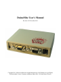
DuinoMite User's Manual
Revision 1.03 December 2011
Copyright 2011, Olimex Ltd (Based on original Maximite by Geoff Graham www.geoffg.net)
Released under Creative Commons Attribution Share Alike 3.0 United States Licensee
1. INTRODUCTION
DuinoMite is a series of compact development boards based on the PIC32 microcontroller from
Microchip Technology Inc.
The DuinoMite is a complete computer, running a BASIC interpreter called MM-Basic (originally
written by Geoff Graham), which when interfaced with a PS2 keyboard and VGA monitor, is
reminiscent of the old retro APPLE][ and TRS-80 personal computers. No need for a PC, no need for
compilers IDEs, programmers, all you need to write embedded applications is DuinoMite.
DuinoMites have ARDUINO shield connectivity, allowing ARDUINO shields to be directly interfaced,
making the DuinoMite the world's first stand alone ARDUINO Single Board Complete BASIC
computer .
DuinoMite is a completely open source platform and the schematic and board files are available for
download from the Olimex (www.olimex.com) web site and released under the Creative Commons
Attribution-Share Alike 3.0 United States License, which generally means that you are free to use these files
to create your own product providing you credit Olimex as the source and release your files with the
same license as well.
The heart of DuinoMite is the PIC32MX795F512 which, amongst others, includes the following
features: On-Chip: 80Mhz clock operation, 512KB Flash memory, 128KB RAM memory, USB with
OTG functionality, UARTs, SPIs, I2C, ADC, CAN, PMP.
Three DuinoMite boards are in production:
DuinoMite-Mega
http://www.olimex.com/dev/DUINO/duinomite-mega.hrml
DuinoMite-Mini
http://www.olimex.com/dev/DUINO/duinomite-mini.hrml
DuinoMite
http://www.olimex.com/dev/DUINO/duinomite.hrml
and two more boards are in design phase at the current date:
DuinoMite-eMega board with Ethernet, Internal Flash and PMP, with possibility for color VGA output.
PIC32-T795 which is a low cost, general purpose, development board for easy bread-boarding using
wire jumpers.
2. BOARDS
2.1. DuinoMite-Mega
This is, to date, the most sophisticated board from DuinoMite range of boards.
The schematic of the current revision of the DuinoMite-Mega can be found online in the DUINO
section at http://www.olimex.com/dev, you will also find the CAD schematics and board files.
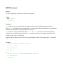
DuinoMite-Mega is available for sale as either a pre-assembled board only or alternatively, in a laser
cut, custom made plastic enclosure:
Hardware features:
–
–
–
–
–
–
–
–
–
–
–
–
–
–
–
–
–
–
–
–
–
–
PIC32MX795F512H processor running at 80Mhz with 128KB RAM and 512KB Flash
DC-DC power supply 9-30V DC input
USB Device / USB Host OTG
mini SD card socket
two UEXT connectors, one inside enclosure, one outside
CAN connector
GPIO connector
ARDUINO shield connector
PS2 Keyboard connector
RS232 connector
VGA connector
Audio RCA jack
Composite Video RCA jack
Headphones 3.5 mm jack
RESET and USER buttons
three status LEDs
build-in LiPo Lithium-Polimer battery charger
ultra low power design which allow down to 30uA current consumption
Industrial temperature operation -40+85C
Noise immunity
ICSP programming connector for programming and debugging
32,768 KHz low frequency crystal allow implementation of RTC and low power modes
2.2. DuinoMite-Mini
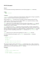
This is the compact, low cost, entry level board with size of only 65 mm x 50 mm.
The schematic of the current revision of DuinoMite-Mini is at http://www.olimex.com/dev in the
DUINO section, where you can also find the CAD schematic and board files.
Hardware features:
– PIC32MX795F512H processor running at 80Mhz with 128KB RAM and 512KB Flash
– Linear power regulator, require EXACTLY 5V to the DC POWER JACK
– USB Device DuinoMite-Mini can take power from USB also, there is 3 way jumper
which selects which source is used the DC POWER JACK or the USB
– mini SD card socket
– UEXT connector
– GPIO connector
– PS2 Keyboard connector
– VGA connector
– RESET button
– USER buttons
– three status LEDs
– Commercial temperature operation -0+70C
– Noise immunity
– ICSP programming connector for programming and debugging
– 32,768 KHz low frequency crystal allow implementation of RTC and low power modes
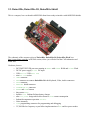
2.3. DuinoMite, DuinoMite-IO, DuinoMite-Shield
This is a compact, low cost board in ARDUINO form factor ready to interface with ARDUINO shields.
The schematic of the current revision of DuinoMite, DuinoMite-IO, DuinoMite-Shield is at
http://www.olimex.com/dev in DUINO section, where you will also find the CAD schematics and
board files.
Hardware features:
–
–
–
–
–
–
–
–
–
–
–
–
–
–
–
–
–
PIC32MX795F512H processor running at 80Mhz with 128KB RAM and 512KB Flash
DC-DC power supply 9-30V DC input
USB Device / USB Host OTG
mini SD card socket
UEXT connector
EXT connector to connect DuinoMite-IO with Keyboard, Video, Audio connectors
GPIO connector
ARDUINO shield connector
DUINOMITE-IO connector
RESET and USER buttons
three status LEDs
build-in LiPo Lithium-Polimer battery charger
ultra low power design which allow down to 30uA current consumption
Industrial temperature operation -40+85C
Noise immunity
ICSP programming connector for programming and debugging
32,768 KHz low frequency crystal allow implementation of RTC and low power modes
2.4. DuinoMite-eMega
This is a new Ethernet enabled board, still in development. The features will be similar to the
DuinoMite-Mega, but with some additional features such as Ethernet connector and PHY controller,
which will add a 100Mbit Ethernet interface to DuinoMite, 2MB on board Data Flash which could be
used as disk for data and code storage. PMP external connector with 80Mhz clock which could be used
to interface to TFT displays, fast ADCs, allowing Duinomite to be used as Logic Analyzer, Digital
Storage oscilloscope, capture for fast external signals.
2.3. PIC32-T795 (breadboarding PIC32MX795)
This is a new breadboard based on Ken Segler's design. It is T-shaped and is intended to plug into a
breadboard. It incorporates a UEXT connector and USB with Device and Host (OTG)
PIC32-T795 is the fastest way to make something with a breadboard and Jumper wires without the
need to solder.
PIC32-T795 can be reused many times as no soldering is required.
3. HARDWARE
3.1. POWER Supply
3.1.1. DuinoMite-Mega
DuinoMite-Mega can be powered by four different sources:
- POWER JACK with a 2.1 mm internal pin and 6 mm outer diameter, the inner pin is positive,
the voltage that the DuinoMite-Mega accepts on this connector is in range 9-30V DC, note that there
is a DC / DC power supply implemented, so the power consumption of this board is the same no matter
what the input voltage is, other similar boards we have seen use linear voltage regulators heat up when
a higher voltage is applied and wastes energy. There is a reverse voltage protection diode on this
connector, to protect against reverse polarity.
- USB power supply, when DuinoMite-Mega is connected via a USB cable to a USB host it will
take its 5V power supply from the USB host source to power the board, note that depending on what
frequency the DuinoMite-Mega runs at, it may consume up to 140mA, so the USB port needs to be able
to provide this current, some USB ports are set to 100mA maximum current supply and may be not able
to power the DuinoMite-Mega.
- Lithium-Polimer battery, DuinoMite-Mega hardware is build to be very power efficient. In
Low Power mode DuinoMite-Mega consumes only 30uA (plus current draw from the I/O pins) while
the RTC low frequency clock is running, so this allows handheld and battery powered devices to be
built with the DuinoMite.
- VIN port on the Arduino platform Connector 1. Note that on this connector there is NO reverse
protection diode, so you should make sure 9-30V DC is applied to this port.
DuinoMite-Mega could be powered by more than one power source at the same time, for instance
POWER JACK and USB at same time. The different power sources have different priorities, this
means when two or more power sources are available at the same time only one of them is used.
The priority is the POWER JACK and VIN, if the power supply is applied to any of these two
connectors, the power is sourced from them and not from the USB and/or the battery, second priority is
USB, if there is no power applied to POWER JACK or VIN and USB is active then the power will be
taken from the USB. The battery power supply is with lowest priority and board will take power from it
only if there is no power supply to any of the other sources.
DuinoMite-Mega has a built in LiPo battery charger, so once it senses power on POWER JACK, USB
or VIN it will charge the LiPo battery (If present) until the battery is charged to 100%.
The switching between the different power supplies is done automatically and glitch free with no need
to change jumpers. Board power is not lost during voltage source switching.
The LiPo battery with 3.7V 1400mA capacity and JST connector for DuinoMite-Mega is available
from Olimex. At maximum frequency with a VGA monitor connected the consumption is 125mA which
will allow the DuinoMite-Mega to run about 10 hours on battery.
As the external power supply utilises a DC/DC converter and not a linear voltage regulator the
DuinoMite-Mega power consumption when running at maximum frequency and with a VGA monitor
and keyboard attached is 100mA when the input power supply is 12VDC. (at 30VDC the current will
drop to 40mA and will rise to 130mA at 9VDC).
3.1.2. DuinoMite-Mini
The DuinoMite-Mini power supply is made with a linear voltage regulator to save cost (an LM1117 is
used). The power source could be USB connector or POWER JACK. The source is selected with a 3way jumper. The board has a protection ZENER diode (6.8V) on the input to protect the board from
over-voltage spikes on the power supply.
Note
The external power supply applied to the POWER JACK must be 5V REGULATED. Note that applying
non-regulated or voltage above 5V could DESTROY the DuinoMite-Mini.
Our recommendation is to use USB to power this board or the cheap `under $2' power supply adapters
for iPods, iPads, e-readers etc. which are with specification 5V/1A and are available on eBay.
3.1.3. DuinoMite
The DuinoMite has same sophisticated power supply like DuinoMite-Mega and allows power supply
9-30VDC.
3.2. USB
The PIC32MX795 has a USB controller which can work in two modes:
- USB device, in this mode you can make USB HID devices or USB CDC devices and emulate
such devices like Keyboard, Mouse, Serial port etc., this mode is supported by all DuinoMite boards.
- USB On-The-Go (OTG) host/device mode in which the USB host PIC32 can interface USB
mouse, USB keyboard, USB camera, USB printers, USB Bluetooth, WiFi modules, USB memory stick
etc. Of course all of these devices need proper drivers to be implemented. This mode is not yet
supported by DuinoMite-Mini board.
Special care is taken in the DuinoMite design for USB noise immunity and protection when it works in
host mode.
When working as USB host DuinoMite may provide up to 500mA to the USB devices attached, so this
should be taken into account when you size the power supply input voltage/current.
MM-BASIC uses USB as an HID device during boot-loading when new firmware is updating, then as a
CDC serial port to establish a virtual console from which you can write your MM-BASIC code via a
terminal program with a USB connection, thus there is no need to use a VGA monitor or PS2
Keyboard.
USB-FAULT signal is low when there is no power supplied to either the USB or the POWER JACK. It
is connected to port RG7 and could be used to detect when you are powered only on battery.
3.3. SD-CARD
A micro SD card connector is available on DuinoMite-Mega, DuinoMite-Mini, DuinoMite-eMega and
DuinoMite boards, this connector is with push-push action to insert and remove the card.
The uSD power supply is designed with ferrite bead filtering to minimise noise problems.
As DuinoMite, and DuinoMite-Mega are designed to be low power boards there is provision for the
SD-card power supply to be shut down, this is done with FET2 connected to STB_E on RB13 port of
PIC32.
SD-CARD presence is sensed by the SD_#CS connected to RD5 port, there is low pull down made
with 100K on this port so when there is no card inserted RD5 is read as 0, when SD card is inserted it
have 10K pullup inside which pull RD5 high and it's read as 1.
Note that the SPI used for the SD card is also wired to UEXT and ARDUINO connectors, so
programmer should take care of this when writing their code.
3.4. UEXT
The UEXT connector is a 10 pin connector which have the following signals: 3.3V power supply,
GND, Serial RX, Serial TX, SPI MOSI, SPI MISO, SPI CLK, I2C CLK, I2C DATA.
By having these signals available on a fixed interface allows us to develop different modules which can
be used on any board with a UEXT connector.
All DuinoMite boards have UEXT connectors and can interface Olimex's UEXT modules.
For more information on UEXT see: http://www.olimex.com/dev/OTHER/UEXT.pdf
Please look at the example section of this manual for sample MM-BASIC code for various modules.
The DuinoMite-Mega has two UEXT connectors one internal and one external.
3.5. ARDUINO SHIELDS
ARDUINO is popular platform for development by beginners and people with little knowledge in
electronics. This platform is gaining popularity and there are lot of projects using it. Arduino allows
various hardware modules to be stacked on top of each other. They are called SHIELDS.
DuinoMite and DuinoMite-Mega have this connector to allow ARDUINO SHIELDS to be connected.
This connector is also very useful for jumper wiring to an external breadboard.
The DuinoMite-Mini has no ARDUINO shield connector on board but has the 26pin GPIO connector
which can be connected to an external DuinoMite-Shield board, which adds the ARDUINO SHIELD,
connected via a 26 pin ribbon cable.
The ARDUINO SHIELD has these signals:
D0,D1,D2,D3,D4,D5,D6,D7,D8,D9,D10,D11,D12,D13,
AREF, A0,A1,A2,A3,A4,A5
VIN, GND, 5V, 3.3V, RST, CTS, RTS
D0 – D13 are digital I/Os,
A0-A5 are analog I/Os,
VIN – input power which allows you to power DuinoMite (or Mega) by an external power supply
RST – reset
CTS, RTS – handshake signals from the Mega's RS232 connector, they are TTL levels.
MM-BASIC can access ARDUINIO SHIELDS with the PIN() function.
These ports may be digital inputs, digital outputs and analog inputs, note max voltage to these ports
should not exceed 3.3V as they may be damaged:
ARDUINO.A0
ARDUINO.A1
ARDUINO.A2
ARDUINO.A3
ARDUINO.A4
ARDUINO.A5
→
→
→
→
→
→
PIN(1)
PIN(2)
PIN(3)
PIN(4)
PIN(5)
PIN(6)
These ports may be digital inputs, digital outputs, they are 5V tolerant, so the maximum input voltage
which you should apply to them should not exceed 5V.
ARDUINO.D0
ARDUINO.D1
ARDUINO.D2
ARDUINO.D3
ARDUINO.D4
ARDUINO.D5
ARDUINO.D6
ARDUINO.D7
→
→
→
→
→
→
→
→
PIN(11)
PIN(12)
PIN(13)
PIN(14)
PIN(15)
PIN(16)
PIN(17)
PIN(18)
→
→
→
→
→
→
COM1:RX →
COM1:TX →
COM1:RTS
COM1:CTS
COM2:RX
COM2:TX
COM4:RX from RS232 connector
COM4:TX from RS232 connector
NOTES!
D0 & D1 are wired via protection resistors to the RS232 connector (COM4) on the DuinoMite-Mega
this means that if there are signals on the RS232 connector they will affect D0, if D1 is initialized as
INPUT this signal will merge with the signal on ARDUINO.D0 connector. Also if D1 is initialized as
output it will affect COM4 port transmission. If you want to separate COM4 from D0 and D1 you can
do this by removing R2 and R3.
As COM1: TX, RX are available on same D0 D1 ports anyway, R2 and R3 may be removed unless you
need a fast UART there.
These ports share more than one function together and should be used with care:
ARDUINO.D8
ARDUINO.D9
ARDUINO.D10
ARDUINO.D11
ARDUINO.D12
ARDUINO.D13
→
→
→
→
→
→
PIN(19)
PIN(20)
PIN(7)
PIN(8)
PIN(9)
PIN(10)
→
→
→
→
→
→
UEXT.CS/VIDEO.SELECT
LED2(YELLOW) VGA.SYNC
UEXT/SD.CARD.SS
UEXT/SD.CARD.MOSI
UEXT/SD.CARD.MISO
UEXT/SD.CARD.CLK
NOTES!!
If you use UEXT.SPI or SD-CARD note that the SPI signals also go to ARDUINO.D10-D13.
ARDUINO.D8 is shared with VIDEO.SELECT and UEXT.CS
3.6. CAN
Controller Area Network (CAN or CAN-bus) is a bus standard, generally used in the automotive
industry, designed to allow micro-controllers and devices to communicate with each other within a
vehicle, and without a host computer.
CAN is available only on the DuinoMite-Mega.
CAN is a very useful interface, it’s the de-facto standard for automotive bus applications, so by having
CAN it would be possible to connect to your car and read all of the data sensors for speed,
temperatures, fuel consumption, etc. This video can give you rough idea what you can do with CAN
and DuinoMite-Mega. http://www.youtube.com/watch?v=PbA_bOO2mMw
Being a robust and noise immune protocol, CAN is used not only in automotive but also in industrial
robot applications – For more information see the following links
http://en.wikipedia.org/wiki/DeviceNet
http://en.wikipedia.org/wiki/CANopen
CAN is not supported currently in MM-BASIC, but in a future firmware CAN will be implemented to
be seen as a file, the same as the COM ports, so you will be able to do OPEN “CAN” AS #1 and use
INPUT # , INPUT$ and PRINT # to send and receive CAN messages.
The CAN connector consists of these 3 signals:
CAN-H, CAN-L – these are the CAN physical layer twisted pair
GND - the shielding connection
The CAN end node should have termination resistor and if CAN-T is soldered (shorted) add such
termination resistor to the CAN bus.
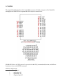
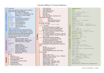
3.7. GPIO
The original MaxiMite introduced the 26 pin GPIO connector. With the emergence of the DuinoMite
and support for ARDUINO we expanded the GPIO layout as shown below:
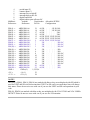
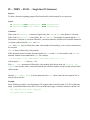
MM-BASIC allows the GPIO ports to be accessed with the PIN() command and function, and different
functions to be set with SETPIN command.
SETPIN configurations:
0
- not defined
1
- analog input AI
2
- digital input DI
3
- frequency input FI
4
5
6
7
8
9
MMBasic
Referrence:
- period input PI
- counter input CI
- interrupt low-to-high IP
- interrupt high-to-low IN
- digital output DO
- digital output open collector OC
Arduino
26pin header
Referrence
Pin No.
PIN(1) →
PIN(2) →
PIN(3) →
PIN(4) →
PIN(5) →
PIN(6) →
PIN(7) →
PIN(8) →
PIN(9) →
PIN(10)→
PIN(11)→
PIN(12)→
PIN(13)→
PIN(14)→
PIN(15)→
PIN(16)→
PIN(17)→
PIN(18)→
PIN(19)→
PIN(20)→
GND→
+5V→
+3.3V →
ARDUINO.A0
ARDUINO.A1
ARDUINO.A2
ARDUINO.A3
ARDUINO.A4
ARDUINO.A5
ARDUINO.D10
ARDUINO.D11
ARDUINO.D12
ARDUINO.D13
ARDUINO.D0
ARDUINO.D1
ARDUINO.D2
ARDUINO.D3
ARDUINO.D4
ARDUINO.D5
ARDUINO.D6
ARDUINO.D7
ARDUINO.D8
ARDUINO.D9
GND (x3)
+5v (1)
+3.3v (1)
Allowable SETPIN
Configurations
21 AI, DI, , , , IP, IN, DO,
19 AI, DI, , , , IP, IN, DO,
17 AI, DI, , , , , , DO,
15 AI, DI, , , , , , DO,
13 AI, DI, FI, PI, CI, IP, IN, DO,
11 AI, DI, FI, PI, CI, IP, IN, DO,
9
AI, DI, FI, PI, CI, IP, IN, DO,
7
, DI, , , , , , DO, OC
5
, DI, , , , , , DO, OC
3
, DI, , , , , , DO, OC
4
, DI, , , , , , DO,
6
, DI, , , , , , DO,
8
, DI, , , , , , DO, OC
10
, DI, , , , , , DO, OC
12
, DI, , , , , , DO, OC
14
, DI, , , , , , DO, OC
16
, DI, , , , , , DO, OC
18
, DI, , , , , , DO, OC
20
AI, DI, , , , , , DO,
22
AI, DI, , , , , , DO,
1,2,25,26
23
24
NOTE!!
The PIN(7), PIN(8), PIN(9), PIN(10) are marked with blue as they are multiplexed with SPI which is
used for UEXT and SD-card, this means that if UEXT or SD-card is accessed these lines will change
their states. Please do not use or use with care if you use also UEXT and SD-card operations in your
code.
PIN(19), PIN(20) are marked with blue as they are multiplexed with VGA.VSYNC and VGA.VIDEODETECT. Please do not use or use with care if you use also VGA monitor.
3.8. PS-2 KEYBOARD
PS2 keyboard CLOCK is connected to RD6 and DATA is connected to RD7.
Note that the Keyboard requires 5V to work correctly, so the keyboard will not work when the
DuinoMite-Mega is powered by 3.7V LiPo battery.
3.9. VGA / Video
The VGA monitor is uses the PIC32 SPI to generate the video signal.
VGA.HSYNC is generated by RD4, VGA.VSYNC is generated by RB12 which is also connected to
LED2 (YELLOW) and ARDUINO.D9.
VGA R/G/B signals are connected together via small SMD jumpers if you selectively cut them you can
make your Video output RED, GREEN, BLUE, AMBER or YELLOW in color.
PIC32 RG8, RG9 generates the Video signal.
Composite video signal is also generated if VGA monitor is not detected. The composite video is
output to the VIDEO RCA connector. PAL, SECAM, NTSC modes are supported, note that in
Composite Video mode the screen resolution is lower than VGA mode.
3.10. AUDIO
The DuinoMite has two connectors, an AUDIO RCA jack connector and a 3.5mm headphone
connector. MM-BASIC can output to these connectors with the SOUND command, with frequencies
up to 1Mhz, and by using the duty cycle parameter, PWM will be available from these connectors.
3.11. LEDS
The DuinoMite has three LEDs:
–RED power supply LED, is ON when the board is powered by external power supply or USB,
and is OFF if the power supply is the LiPo battery.
–YELLOW is the system RUN status, if this LED is ON, VGA video is generated correctly and
the board is ready to work.
–GREEN this is SD card activity LED and is ON when SD-card is accessed. PIN(0) will also drive
this LED on and off.
3.12. BUTTONS
The DuinoMite has two buttons: RESET and USER BUTTON.
RESET button does a hardware reset (hot start) and all code in memory is cleared and board initialized
as if it was just powered up.
The Duinomite has a boot-loader which allows the firmware to be upgraded without need of an
external programmer. To enter the boot-loader the USER button should be pressed at power-up or
RESET. To enter the boot-loader press and hold USER button, then press and release RESET button.
When you release the USER button the YELLOW and GREEN LEDs will blink alternately to show
that the board is in boot-loading mode. To load the new firmware run the Bootloader.exe and select the
new HEX code.
The USER button status can also be read with the PIN(0) function.
3.13. BATTERY
The DuinoMite and DuinoMite-Mega have a built-in LiPo battery charger and the hardware is
designed to allow them to run in low power mode for battery operation.
USB-FAULT is connected to RG7 to allow the firmware to be aware that it is running on battery
instead of an external power supply. If USB-FAULT is read as 0 the board is powered by battery.
The battery charge state can be monitored by measuring the power supply on BAT port RB2.
The Lithium Polimer battery is connected via the R31/R29 voltage divider (0.319727891) to RB2 port
as RB2 can handle a maximum voltage of 3.3V but the battery voltage can go up to 4.2V when
completely charged.
DM firmware adds PIN(21) analog input pin which could be used for Battery voltage monitoring. Note
that voltage is sensed through voltage vivider as PIC32 inputs can't measure more than 3.3V while LiPo battery voltage may go up to 4.2V when completely loaded. This is why the measured values from
PIN(21) should be multiplied by the magic number 3.13 to get the real battery voltage.
3.14. HARDWARE SIGNATURE
The DuinoMite hardware signature allows the firmware to be aware of which board it is running. This
is very useful for the boot-loader to determine which firmware to download to it. The signature is done
by a voltage divider made from R40/R30 read on RB14 initialized as analog input. For the current
revision of the hardware the voltage divider is 1:10 so if 0.33V is read on this port your code runs on
the DuinoMite hardware.
4. SOFTWARE
4.1. DIRECT PROGRAMMING USING MPLAB, C32, PIC-KIT3
By programming in C you will have access to all processor resources.
What you will need is:
–Obtain MPLAB-X and the C32 compiler from Microchip ( http://www.microchip.com) and
download the latest DuinoMite firmware from Olimex ( http://www.olimex.com)
–we assume you already have a PIC32 programmer/debugger, if you do not have you may need
to obtain the PIC-KIT3 and PIC-ICSP, note that you will need the PIC-ICSP even if you have
the Microchip programmer as DuinoMite uses a small 0.05” ICSP connector instead of the
more common 0.10" ICSP connector.
With this setup you have access to a complete development environment which works on Windows,
Linux, MAC OS and you can use all of the hardware features of DuinoMite boards.
4.2. PINGUINO IDE
The Pinguino Project is a complete integrated IDE and C compiler. It works with the boot-loader so
there is no need for programmers etc. when you program using the Pinguino IDE. The project page is at
http://www.pinguino.cc
Pinguino implements the ARDUINO like language which is generally C++ libraries to allow easy
programming of the hardware.
The DuinoMite boards are based on our PIC32-PINGUINO-OTG project hardware and evolved from
there, so they can use the existing Pinguino programming environment, the only difference is that a
different boot-loader should be programmed into the DuinoMite to support Pinguino IDE.
The Pinguino IDE allows you to program the DuinoMite in ARDUINO language or pure C/C++ and
load the code with a single mouse click.
4.3. MM-BASIC
MM-BASIC was developed by Geoff Graham, you can see the original MaxiMite project at
http://www.geoffg.net
What distinguishes the MM-BASIC, and the original MaxiMite design, from all other development
boards and tools is that it is a single chip, complete computer solution with a PS2 keyboard and VGA
monitor support, so all you need for development is one small computer board which is build around
the powerful PIC32MX795 microcontroller.
DuinoMite was started with the ambition to improve the current MaxiMite hardware by adding some
hardware features that we felt were missing in the original design, low power, battery operation, real
UARTs, CAN, Arduino shield connector, UEXT connector, RTC support, Ethernet, etc.
4.3.1. SOFTWARE INSTALLATION AND UPGRADE
DuinoMite can reprogram itself with a new version of its firmware – also known as firmware
upgrading . This is done with the help of small program called bootloader. The same firmware is loaded
on all DuinoMite boards, there is no difference.
To start the bootloader software press and hold the BUT button then press and relese RESET button.
The green and yellow LEDs will start flashing.
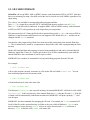
4.3.1.1 Bootloader.exe For Windows:
The firmware upgrades can be downloaded from Olimex web site. On your PC run the program called
“BootLoader.exe”, and follow the instructions included in the upgrade package to re program the
DuinoMite with the new version.
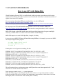
4.3.1.2 MPHIDFLASH
For Linux:
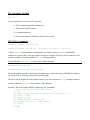
Download mphidflash from http://code.google.com/p/mphidflash/
Before you install it, make sure you have installed libhid-dev on your computer:
$ sudo apt-get install libhid-dev
then go to the directory where you downloaded and unpacked mphidflash and do:
$ make
then:
$ sudo make install
now the mphidflash is installed in /usr/local/bin folder and you can access it from anywhere, to load
new firmware put DuinoMite in bootloader mode then type:
$ mphidflash -w firmware.hex -v 15ba -p 0032 -r
For MAC OS:
download the mphidflash binary and use like this:
./mphidflash -w firmware.hex -v 15ba -p 0032 -r
4.3.1.3 PIC32PROG
For Linux:
Download PIC32PROG from http://code.google.com/p/pic32prog/
you can use svn:
$ svn checkout http://pic32prog.googlecode.com/svn/trunk/ pic32prog
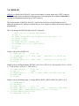
4.3.2. GETTING STARTED
DuinoMite could work with PS2 keyboard and VGA monitor, or with terminal via PC. So to get started
you will need either PS2 keyboard and VGA monitor, either USB cable and PC.
STAND ALONE USE:
If you use PS2 Keyboard and VGA just plug them to the board and power it.
You will see on the VGA monitor this message:
MaxiMite BASIC Version x.xx
Copyright 2011, Geoff Graham
Olimex Port By kenseglerdesigns.com
>
the “>” prompt show that DuinoMite is ready to complete your commands.
BASIC is interpreter language which means that the instructions are decoded at execution time. All
Basic interpreters allow instructions to be executed at command prompt too.
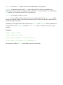
First code on every language is to print ”HELLO WORLD” this could be done in BASIC like this:
> PRINT “Hello world!”
the result will be :
Hello world!
>
CONSOLE USE:
If you do not have PS2 keyboard and VGA monitor but have PC you still can develop with Duinomite
by using it's virtual USB console. To do this you need mini USB cable, which you should plug to your
PC and DuinoMite. When you do this the red LED power will turn on along with the yellow LED
which indicates the video sync and PIC32 CPU chip is good. The green LED indicates SD card activity.
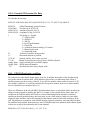
LINUX:
If you use Linux the DuinoMite drivers will be automatically recognized and installed.
Open console and install minicom terminal program.
$ sudo apt-get install minicom
Then you should locate which virtual communication port is DuinoMite by running this command:.
$ dmesg | grep tty
You will see cdc_acm driver something like:
[103473.694556] cdc_acm 5-1:1.0: ttyACM0: USB ACM device
Please remember ttyACM0: as you have to setup minicom to use it:
$ minicom -s
Setup the serial port to ttyACM0: and you will see the greet message:
MaxiMite BASIC Version x.xx
Copyright 2011, Geoff Graham
Olimex Port By kenseglerdesigns.com
>
WINDOWS:
If you use Windows it will try to search for drivers and will / should fail, so you have to download files
from the Olimex website under DuinoMite-Mega "software" the "Duinomite drivers for virutal com
port console" Unzipped it and store it in a folder that can be easily remembered. Then under control
panel, system, hardware, device manager go to the named device "Duinomite" and update its driver to
point to the "files" unzipped. After the driver installation is complete the new port number will show up
for the DuinoMite under [Ports - COM & LPT] Please take note of this port number!
Now you can use terminal program like Putty, Terraterm, MMIDE etc.
5. MM-BASIC LANGUAGE
5.1. MM-BASIC INTRODUCTION
BASIC is an interpreted language, this means as you type the commands on the command prompt they
execute immediately, if you type a line number before the command it is stored in memory, then by
using the RUN command you can execute the stored commands in the order defined by the line
numbers.
For instance, if you type:
> PRINT 22/7
3.14286
i.e. the command is executed immediately
But if you type
20 PRINT 22/7
The code will be not executed until the command RUN is typed.
If you want to clear the screen first you can add:
10 CLS
Now if you want to see what code is in memory, you can do this with the LIST command:
> LIST
10 CLS
20 PRINT 22/7
>
To replace a line you simply enter the new line with the same line number as the one you are replacing,
to delete a line you enter the line number on its own (without any following text).
BASIC automatically keeps the lines sorted in ascending order so when you run or list a program it will
start with the smallest line number first.
Pressing CTRL+C during a running program run will break the execution and return to the “>” prompt.
A program line held in memory can be changed using the EDIT command or by entering a new line
with the same number thereby overwriting it. A line can be deleted by entering its number on its own.
All program lines may be cleared from working memory with the NEW command.
Multiple commands separated by a colon can be entered on the one line (as in INPUT A : PRINT B).
5.2. KEYBOARD / DISPLAY
Input can come from either a keyboard or from a computer using a terminal emulator via the USB or
serial interfaces. Both the keyboard and the USB interface can be used simultaneously and can be
detached or attached at any time without affecting a running program.
Output will be simultaneously sent to the USB interface and the video display (VGA or composite).
Either can be attached or removed at any time.
Keyboard
A standard IBM compatible PS2 keyboard with a mini-DIN connector or a compatible USB keyboard
and a USB/mini-DIN adapter.
Non ASCII keys (such as the function keys) are mapped to ASCII characters. Use a command like
PRINT HEX$(ASC(INKEY$)) to check the actual mapping.
VGA
Standard monochrome VGA (31.5KHz horizontal scanning with 60Hz vertical refresh). 480x432
pixel graphic screen. 80 characters per line and 36 lines per screen
Composite
Standard monochrome PAL (15.625KHz horizontal scanning with 50Hz vertical refresh non
interlaced). 304x216 pixel graphic screen. 50 characters per line and 18 lines per screen. SECAM
and NTSC output is also available and possible to be configured with the SETUP command.
Video Output selector
The DuinoMite hardware will auto detect when a VGA monitor is attached, so if the VGA monitor is
attached MM-BASIC will generate a VGA signal, if no VGA monitor is attached it automatically will
output Composite VIDEO. No need to open/close jumpers.
5.3. SD CARD STORAGE
DuinoMite will accept MMC, uSD or uSDHC memory cards formatted as FAT16 or FAT32. Note that
there is no advantage in using a fast uSD card as the card is clocked at a fixed 20MHz, regardless of its
speed rating.
Two “drives” are available for storing and loading programs and data:
Drive “A:” is a virtual drive using the PIC32’s internal flash memory and has a size of 256KB.
Drive “B:” is the SD card (if connected). It supports MMC, uSD or uSDHC memory cards formatted
as FAT16 or FAT32 with capacities up to the largest that you can purchase.
File names must be in 8.3 format prefixed with an optional drive prefix A: or B: (the same as DOS or
Windows). Long file names and directories are not supported. The default drive is B: and this can be
changed with the DRIVE command.
Note that the video output will go blank for a short time while writing data to the internal flash drive
A:. This is normal and is caused by a requirement to shut off the video while reprogramming the flash
memory.
On the uSD card both data and programs are stored using standard text and can be read and edited in
Windows, Apple Mac, Linux, etc. A uSD card can have up to 10 files simultaneously open while the
internal flash drive has a maximum of one file open at a time.
MM-BASIC has a number of commands for saving and loading programs from the SD card.
For example:
> SAVE “MYPROG.BAS”
will save the program currently in memory to a file on the SD card called MYPROG.BAS. You can
later load that program back into memory with:
> LOAD “MYPROG.BAS”
or both load and run it at the same time with:
> RUN “MYPROG.BAS”
The filename AUTORUN.BAS has a special meaning. On startup MM-BASIC will look for a file called
“AUTORUN.BAS” in the root directory of the internal flash drive (A:) then the SD card (B:). If the file
is found it will be automatically loaded and run otherwise MM-BASIC will print a prompt (“>”) and
wait for input.
MM-BASIC also has commands for managing the SD card. For example, the FILES command will
list all of the files in the current directory (or folder as they are called in Windows). CHDIR can be
used to change to a new directory, MKDIR will create a new directory and RMDIR will delete a
directory. KILL will delete a file, NAME will rename file.
Whenever specified, a file name can be a string constant (i.e. enclosed in double quotes) or a string
variable. This means you must use double quotes if you are directly specifying a file name. Eg,:
> RUN “TEST.BAS”
If the extension is omitted the .BAS extension will be added automatically i.e.
> RUN “TEST”
Inside a running program you can save and read data to and from the SD card. First a file must be
opened using the OPEN command and then you can use the PRINT, WRITE, INPUT, LINE INPUT,
INPUT$ commands to write and read from the card.
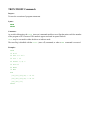
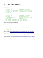
For example, the following code example will save the values of three variables into a file:
200
210
220
230
240
OPEN “MYDAT.DAT” FOR OUTPUT AS #1
PRINT #1, VAR1
PRINT #1, VAR2
PRINT #1, VAR3
CLOSE #1
Files can be opened for input, output and append and you can have up to 10 files open simultaneously.
The XMODEM command can be used to copy files to and from the internal flash drive or SD card. This
is particularly valuable when there is no SD card present and the internal flash drive is being used for
storage.
5.5. GRAPHICS
Graphics commands operate on the video output only. Coordinates are measured in pixels with x being
the horizontal coordinate and y the vertical coordinate.
The top left of the screen is at location X=0 and Y=0 and the bottom right of the screen defined by the
read only variables X = MM.HRES and Y = MM.VRES which change depending on the video mode
selected (VGA or composite).
Increasing positive numbers represent movement down the screen and to the right.
MM-BASIC has commands for clearing the screen (CLS), turning a pixel on or off (PIXEL), drawing
lines and boxes (LINE), drawing a circle (CIRCLE) and saving the video screen as a BMP file
(SAVEBMP).
You can also position text anywhere on the screen by using the LOCATE command.
For example, the following code example will draw a box and print the word STOP in the middle.
200 LINE(50,75)-(150,125),1,B
210 LOCATE 80,95
220 PRINT “STOP”
5.6. EXTERNAL IO
You can configure an external I/O pin using the SETPIN command, set its output using the PIN()=
command and read the current input value using the PIN() function. Digital I/O uses the number zero
to represent a low voltage and any non zero number for a high voltage. An analogue input will report
the measured voltage as a floating point number.
Four serial ports are supported, COM1 and COM2 with speeds up to 19200 baud with configurable
buffer sizes and optional hardware flow control. COM3 and COM4 with speeds up to 115200 baud.
The serial ports are opened using the OPEN command and any command or function that uses a file
number can be used to send and receive data.
Communications to slave or master devices on an I2C bus is supported with eight commands. MMBASIC fully supports bus master and slave mode, 10 bit addressing, address masking and general call,
as well as bus arbitration (i.e. bus collisions in a multi master environment).
The Serial Peripheral Interface (SPI) communications protocol is supported with the SPI command.
A high performance Pulse Width Modulation (PWM) output is also available by utilising the sound
connector and specifying an optional duty cycle parameter to the SOUND command.
5.7. TIMING
You can get the current date/time using the DATE$ and TIME$ functions and you can set them by
assigning the new date and time to them. If not set the calendar will start from midnight 1st Jan 2000
on power up.
You can freeze program execution for a number of milliseconds using PAUSE.
MM-BASIC also maintains an internal stopwatch function (the TIMER function) which counts up in
milliseconds. You can reset the timer to zero or any other number by assigning a value to the TIMER.
Using SETTICK you can setup a “tick” which will generate a regular interrupt with a period from one
millisecond to over a month.
5.8. INTERRUPTS
Any external GPIO I/O pin can be configured to generate an interrupt using the SETPIN command
with up to 21 interrupts (including the tick interrupt) active at any one time.
Interrupts can be set up to occur on a rising or falling digital input signal and will cause an immediate
branch to a specified line number (similar to a GOSUB). The target line number can be the same or
different for each interrupt. Return from an interrupt is via the IRETURN statement. All statements
(including GOSUB/RETURN) can be used within an interrupt.
If two or more interrupts occur at the same time they will be processed in order of pin numbers (ie, an
interrupt on pin 1 will have the highest priority). During processing of an interrupt all other interrupts
are disabled until the interrupt routine returns with an IRETURN. During an interrupt (and at all times)
the value of the interrupt pin can be accessed using the PIN() function.
A periodic interrupt (or regular “tick”) with a period specified in milliseconds can be setup using the
SETTICK statement. This interrupt has the lowest priority.
Interrupts can occur at any time but they are disabled during INPUT statements. If you need to get
input from the keyboard while still accepting interrupts you should use the INKEY$ function.
When using interrupts the main program is completely unaffected by the interrupt activity unless a
variable used by the main program is changed during the interrupt.
For most programs MM-BASIC will respond to an interrupt in under 100uS. To prevent slowing the
main program by too much an interrupt should be short and execute the IRETURN statement as soon
as possible. Also remember to disable an interrupt if you have finished needing it – background
interrupts can cause strange and non intuitive bugs.
5.9. SOUND
The SOUND command will generate a simple square wave between 20Hz and 1MHz lasting for a
specified duration.
This command can also be used to generate a Pulse Width Modulation (PWM) signal.
5.10. VARIABLES
In MM-BASIC all numbers are floating point which means that they can contain a decimal point and
are safe to use in any type of calculation.
Variables names can be up to 32 characters long and can contain alpha numeric letters, the full stop
and underscore characters. This means that you can use meaningful variable names in your program.
For example: BatteryVoltage or test_load2.
MM-BASIC will also work with strings which are a collection of characters. A constant string must be
surrounded by double quotes and string variables are designated with a $ character at the end of the
variable name.
For example:
> FileName$ = “INFIX” + “.DAT”
> PRINT FileName$
INFIX.DAT
>
When used with strings the plus (+) operator will join strings so the above example will join the
constant strings INFIX and .DAT and save the result in a string variable. There are many functions in
MM-BASIC like this that can be used to pull apart and manipulate strings and this capability is one of
the strengths of MM-BASIC.
Another type of variable is the array. MM-BASIC allows arrays of numbers or strings and they can
have up to eight dimensions.
For example, the following sequence of commands will create a three dimensional array with 10
elements in each dimension (a total of 1000 individual numbers) and save a number into the array:
> DIM AData(10,10,10)
> AData(3,5,8) = 1234.5
> PRINT AData(3,5,8)
1234.5
>
5.11. OPERATORS
The following operators, in order of precedence, are recognized.
Operators that are on the same level (for example + and -) are processed with a left to right precedence
as they occur on the program line.
Arithmetic operators:
^
Exponentiation
* / \ MOD
Multiplication, division, integer division and modulus (remainder)
+ Addition and subtraction
examples:
7 ^ 2 =
7 * 2 =
7 / 2 =
7 MOD 2
7 \ 2 =
7 + 2 =
7 – 2 =
49
14
3.5
= 1
3
9
5
Logical operators:
NOT
logical inverse of the value on the right
<> < > <= =< >= => Not equal, less than, greater than, less than or equal to, less than or equal
to (alternative version), greater than or equal to, greater than or equal to
=
(alternative version)
AND OR XOR
Logical AND, Logical OR, Logical Exclusive OR
The operators AND, OR and XOR are bitwise operators.
For example:
> PRINT 3 AND 6 will output 2.
The other logical operations result in the number 0 (zero) for false and 1 for true. For example the
statement PRINT 4 >= 5 will print the number zero on the output and the expression A= 3 > 2
will store +1 in A.
The NOT operator is highest in precedence so it will bind tightly to the next value. For normal use the
expression to be negated should be placed in brackets.
For example: IF NOT (A=3 OR A=8) THEN
String operators:
+
Join two strings
<> < > <= =< >= => Not equal, less than, greater than, less than or equal to, less than or equal
to, greater than or equal to, greater than or equal to
=
Example:
“hello “ + “world” = “hello world”
5.12. EXPRESSIONS
In most cases where a number or string is required you can also use an expression.
For example:
FILENAME$ = “TEST”: RUN FILENAME$ + “.BAS”
Or, as an extreme (and not recommended) example:
NBR = 100: GOTO NBR*3+20
5.13. NAMING CONVERSION
Command names, function names, variable names, file names, etc are not case sensitive, so that "Run"
and "RUN" are equivalent and "dOO" and "Doo" refer to the same variable.
There are two types of variable; numeric which stores a floating point number (eg, 45.386) and string
which stores a string of characters (eg, “Tom”). String variable names are terminated with a $ symbol
(eg, name$) while numeric variables are not.
Variable names can start with an alphabetic character or underscore and can contain any alphabetic or
numeric character, the period (.) and the underscore (_). They may be up to 32 characters long. A
variable name must not be the same as a function or one of the following keywords: THEN, ELSE,
GOTO, GOSUB, TO, STEP, FOR, WHILE, UNTIL, LOAD, MOD, NOT, AND, OR, XOR.
Example:
STEP = 5
is illegal as STEP is a keyword.
5.14. CONSTANTS
Numerical constants may begin with a numeric digit (0-9) for a decimal constant, &H for a
hexadecimal constant, &O for an octal constant or &B for a binary constant.
For example:
&B1000 is the same as the decimal constant 8.
Decimal constants may be preceded with a minus (-) or plus (+) and may terminated with 'E' followed
by an exponent number to denote exponential notation.
For example:
1.6E+4 is the same as 16000.
String constants are surrounded by double quote (“) marks. e.g. “Hello”.
5.15. PRE-DEFINED CONSTANTS
MM.HRES
The horizontal resolution of the current video display screen in pixels.
MM.VRES
The vertical resolution of the current video display screen in pixels.
MM.VER
MM.DRIVE$
The version number of the firmware in the form aa.bbcc where aa is the major version
number, bb is the minor version number and cc is the revision number (normally zero but
A = 01, B = 02, etc).
The current default drive returned as a string containing either “A:” or “B:”.
MM.FNAME$ The name of the file that will be used as the default for the SAVE command. This is set
by LOAD, RUN and SAVE.
MM.ERRNO
Is set to the error number if a statement involving the SD card fails or zero if the
operation succeeds. This is dependent on the setting of OPTION ERROR. The possible
values for MM.ERRNO are:
0 = No error
1 = No SD card found
2 = SD card is write protected
3 = Not enough space
4 = All root directory entries are taken
5 = Invalid filename
6 = Cannot find file
7 = Cannot find directory
8 = File is read only
9 = Cannot open file
10 = Error reading from file
11 = Error writing to file
12 = Not a file
13 = Not a directory
15 = Directory not empty
15 = Hardware error accessing the storage media
5.16. LIMITS
Maximum length of a command line is 255 characters.
Maximum length of a variable name is 32 characters.
Maximum number of dimensions to an array is 8.
Maximum number of arguments to commands that accept a variable number of arguments is 50.
Numbers are stored and manipulated as single precision floating point numbers. The maximum
number that can be represented is 3.40282347e+38 and the minimum is 1.17549435e-38
The range of integers (whole numbers) than can be manipulated without loss of accuracy is
±16777100.
Maximum string length is 255 characters.
Maximum line number is 65000.
Maximum number of files simultaneously open is 10 on the SD card and one on the internal flash
drive (A:).
Maximum SD card size is 2GB formatted with FAT16 or 2TB formatted with FAT32.
Size of the internal flash drive (A:) is 256KB.
Maximum size of a loadable video font is 64 pixels high x 255 pixels wide and 256 characters.
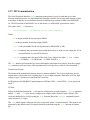
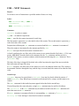
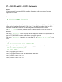
5.17. SPI Communication
The Serial Peripheral Interface (SPI) communications protocol is used to send and receive data
between integrated circuits. As implemented this function is suitable for moving small amounts of data
to and from a chip like an accelerometer but not for shifting large amounts of data from EEPROMS,
etc. The SPI function in MM-BASIC acts as the master (i.e. MM-BASIC generates the clock).
The syntax of the SPI function is:
received_data = SPI(Rx,Tx,Clock[,data[,speed]])
Where:
Rx is the pin number for the data input (MISO)
Tx is the pin number for the data output (MOSI)
clock is the pin number for the clock generated by MM-BASIC (CLK)
data is optional and is an integer representing the data byte to send over the output pin. If it is
not specified the ‘tx’ pin will be held low.
speed is optional and is the speed of the clock. It is a single letter either H, M or L where
H is 500KHz, M is 50KHz and L is 5KHz. Default is H.
The SPI function will return the byte received during the transaction as an integer. Note that a single
SPI transaction will send a byte while simultaneously receiving a byte (which is often discarded).
Transmission Format:
The format of the transmission matches the most common standard. The clock is high when inactive
and the data is valid on the clock’s trailing edge (ie, low to high transition). Data bytes are 8 bits, high
voltage is logic 1 and the most significant bit is sent first.
In SPI parlance the MM-BASIC implementation of SPI has CPOL = 1 and CPHA = 1 or it operates in
mode 3.
I/O Pins:
Before invoking this function the Rx pin must be configured as an input using the SETPIN command
and the Tx and clock pins must be configured as outputs (either normal or open collector). The
clock pin should also be set high (using the PIN function) before the SETPIN command so that it
starts as inactive (i.e. high).
The SPI enable signal is often used to select a slave and “prime” it for data transfer. This signal is not
generated by this function and (if required) should be generated using the PIN function on another
pin.
The SPI function does not “take control” of the I/O pins like the serial and I2C protocols and the
PIN command will continue to operate as normal on them. Also, because the I/O pins can be changed
between function calls it is possible to communicate with many different SPI slaves on different I/O
pins.
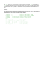
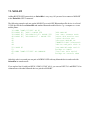
Example:
The following example will send the command &H80 and receive two bytes from the slave SPI device.
Because the speed is not specified it defaults to high (500KHz):
10 SETPIN 1,2
'PIN(1) as Rx digital input
20 SETPIN 2,8
'PIN(2) as Tx digital output
30 PIN(3) = 1: SETPIN 3,8 'PIN(3) clock as output
40 PIN(4) = 1: SETPIN 4,8 'PIN(4) as slave select
50 '
100 PIN(4) = 0
'slave select
110 junk = SPI(1,2,3,&H80) 'send &H80
120 BYTE1 = SPI(1,2,3)
'read first byte
130 BYTE2 = SPI(1,2,3)
'read second byte
140 PIN(4) = 1
'slave de-select
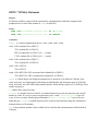
5.18. I2C Communication
The Inter-Integrated-Circuit (I2C) bus was developed by the electronics giant Philips for the transfer of
data between integrated circuits. It has been adopted by many manufacturers and can be used to
communicate with many devices including memories, clocks, displays, speech modules, etc.
This implementation was developed by Gerard Sexton and fully supports master and slave operation,
10 bit addressing, address masking and general call, as well as bus arbitration (i.e. bus collisions in a
multi master environment).
In the master mode, there is a choice of 2 modes - interrupt and normal. In normal mode, the I2C send
and receive commands will not return until the command completes or a timeout occurs (if the timeout
option has been specified). In interrupt mode, the send and receive commands return immediately
allowing other MM-BASIC commands to be executed while the send and receive are in progress.
When the send/receive transactions have completed, an MM-BASIC interrupt will be executed. This
allows you to set a flag or perform some other processing when this occurs.
When enabled the I2C function will use UEXT pins 5 and 6, UEXT.5 becomes the I2C clock line
(SCL) and UEXT.6 becomes the I2C data line (SDA). Both of these pins have pullup resistors (4.7k).
I2C is also connected via R4 and R26 to PIN(5) and PIN(6) → ARDUINO.A4 (SDA) and
ARDUINO.A5 (SCL) .
Be aware that when running the I2C bus at above 150KHz the cabling between the devices becomes
important. Ideally the cables should be as short as possible (to reduce capacitance) and also the data
and clock lines should not run next to each other but have a ground wire between them (to reduce
crosstalk). If the data line is not stable when the clock is high, or the clock line is jittery, the I2C
peripherals can get "confused" and end up locking the bus (normally by holding the clock line low). If
you do not need the higher speeds then operating at 100kHz is the safest choice.
There are four commands for master mode: I2CEN, I2CDIS, I2CSEND and I2RCV.
For slave mode the commands are: I2CSEN, I2SDIS, I2CSSEND and I2CSRCV. The master and
slave modes can be enabled simultaneously however, once a master command is in progress, the slave
function will be "idle" until the master releases the bus. Similarly, if a slave command is in progress,
the master commands will be unavailable until the slave transaction completes.
Both the master and slave modes use an MM-BASIC interrupt to signal a change in status. These
interrupt routines operate the same as a general interrupt on an external I/O pin and must be terminated
with an IRETURN command to return control to the main program when completed. The automatic
variable MM.I2C will hold the result of a command or action.
I2C Master Mode Commands
I2CEN speed, timeout [,interrupt-line]
Enables the I2C module in master mode.
speed is a value between 10 and 400 (for bus speeds 10kHz to 400kHz).
timeout is a value in milliseconds after which the master send and receive commands will be
interrupted if they have not completed. The minimum value is 100. A value of zero will disable the
timeout (though this is not recommended).
interrupt-line is optional. It specifies the line number of an interrupt routine to be run when the
send or receive command completes. If this is not supplied, the send and receive command will only
return when they have completed or timed out. If it is supplied then the send and receive will complete
immediately and the command will execute in the background.
I2CDIS
Disables the slave I2C module. It will also send a stop if the bus is still held.
I2CSEND address, option, snd-len, snd-data [,snd-data]
Send data to the I2C slave device.
address
is the slave I2C address.
cption is a number between 0 and 3 , 1 = keep control of the bus after the command (a stop condition
will not be sent at the completion of the command); 2 = treat the address as a 10 bit address ; 3 =
combine 1 and 2 (hold the bus and use 10 bit addresses).
snd-len is the number of bytes to send.
snd-data is the data to be sent - this can be specified in various ways (all values sent will be between
0 and 255):
The data can be supplied in the command as individual bytes. Example:
I2CSEND &H6F,1,3,&H23,&H43,&H25
The data can be in a one dimensional array (the subscript does not have to be zero and will be
honoured, also bounds checking is performed). Example:
I2CSEND &H6F,1,3,ARRAY(0)
The data can be a string variable (not a constant). Example:
I2CSEND &H6F,1,3,STRING$
The automatic variable MM.I2C will hold the result of the transaction.
I2CRCV address, bus-hold, rcv-len, rcv-buf [, snd-len, snd-data]
Receive data from the I2C slave device with the optional ability to send some data first.
address is the slave I2C address (note that 10 bit addressing is not supported).
option is a number between 0 and 3 ; 1 = keep control of the bus after the command (a stop
condition will not be sent at the completion of the command) ; 2 = treat the address as a 10 bit address;
3 = combine 1 and 2 (hold the bus and use 10 bit addresses).
rcv-len is the number of bytes to receive.
rcv-buf is the variable to receive the data - this is a one dimensional array or if rcv-len is 1 then
this may be a normal variable. The array subscript does not have to be zero and will be honoured, also
bounds checking is performed.
Optionally you can specify data to be sent first using snd-len and snd-data. These parameters are
used the same as in the I2CSEND command (ie, snd-data can be a constant, an array or a string
variable).
Examples:
I2CRCV &H6F,1,1,BYTE
I2CRCV &H6F,1,5, ARR(0)
I2CRCV &H6F,1,4,ARR(2),3,&H12,&H34,&H56
I2CRCV &H6F,1,3,RCVARRAY(0),4,SNDARRAY(0)
The automatic variable MM.I2C will hold the result of the transaction.
I2C Slave Mode Commands
I2CSEN address, mask, option, send-int-line, rcv-int-line
Enables the I2C module in slave mode. address is the slave I2C address
mask is the address mask (bits set as 1 will always match)
option is a number between 0 and 3 ; 1 = allows MM-BASIC to respond to the general call address.
When this occurs the value of MM.I2C will be set to 4; 2 = treat the address as a 10 bit address ; 3 =
combine 1 and 2 (respond to the general call address and use 10 bit addresses).
send-int-line is the line number of a send interrupt routine to be invoked when the module has
detected that the master is expecting data
rcv-int-line is the line number of a receive interrupt routine to be invoked when the module has
received data from the master.
I2CSDIS
Disables the slave I2C module.
I2CSSEND snd-len, snd-data [,snd-data]
Send the data to the I2C master. This command should be used in the send interrupt (ie in the
snd_int-line when the master has requested data). Alternatively a flag can be set in the send
interrupt routine and the command invoked from the main program loop when the flag is set.
snd-len is the number of bytes to send.
snd-data is the data to be sent. This can be specified in various ways, see the I2CSEND commands
for details.
I2CSRCV rcv-len, rcv-buf, rcv-d
Receive data from the I2C master device. This command should be used in the receive interrupt (ie in
the rcv-int-line when the master has sent some data). Alternatively a flag can be set in the
receive interrupt routine and the command invoked from the main program loop when the flag is set.
rcv-len is the maximum number of bytes to receive.
rcv-buf is the variable to receive the data - this is a one dimensional array or if rcv-len is 1 then
this may be a normal variable. The array subscript does not have to be zero and will be honoured, also
bounds checking is performed.
rcv-d will contain actual number of bytes received by the command.
I2C Automatic Variable
MM.I2C
Is set to indicate the result of an I2C operation.
0 = The command completed without error.
1 = Received a NACK response
2 = Command timed out
4 = Received a general call address (when in slave mode)
I2C Utility Command
NUM2BYTE number, array(x) or
NUM2BYTE number, variable1, variable2, variable3, variable4
Convert number to four numbers containing the four separate bytes of number (MM-BASIC
numbers are stored as the C float type and are four bytes in length). The bytes can be returned as four
separate variables, or as four elements of array starting at index x.
See the function BYTE2NUM() for the reverse of this command.
BYTE2NUM(array(x)) or
BYTE2NUM(byte1,byte2,byte3,byte4)
Return the number created by storing the four arguments as consecutive bytes (MM-BASIC numbers
are stored as the C float type and are four bytes in length).
The bytes can be supplied as four separate numbers or as four elements of array starting at index x.
See the command NUM2BYTE for the reverse of this function.
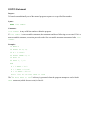
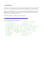
Example: This code changes MOD-IO address by I2C commands:
5 'edit line 40 to change new address
10 CLS
20 INPUT "Press Hold But on MOD-IO then hit enter ";a
30 CurI2c = &h58
40 NewI2c = &h5a
50 I2CEN 100,100 ' Enable I2C
60 I2CSEND CurI2c,1,2, &hf0, NewI2c
70 I2CDIS
80 END
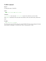
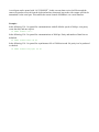
5.19. SERIAL Communication
Four serial ports are available for asynchronous serial communications. They are labeled COM1:,
COM2:, COM3: and COM4: and are opened in a manner similar to opening a file on the SD card.
After they have been opened they will have an associated file number (like an opened disk file) and
you can use any commands that operate with a file number to read and write to/from the serial port.
Finally the serial port can be closed using the CLOSE command.
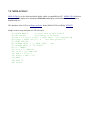
The following is an example:
10
20
30
40
20
OPEN “COM1:9600” AS #3
PRINT #3, “HELLO”
DATA$ = INPUT$(20,#3)
CLOSE #3
SETPIN 2,8
'open serial port
'send hello
'read up to 20 characters
'PIN(2) as Tx digital output
Pin assignments:
COM1:
RX is Arduino.D2 or GPIO.13;
TX is Arduino.D3 or GPIO.14;
RTS is Arduino.D4 or GPIO.15 (if FC is used);
CTS is Arduino.D5 or GPIO.16 (if FC is used);
COM2:
RX is Arduino.D6 or GPIO.17;
TX is Arduino.D7 or GPIO.18;
COM3:
RX is UEXT.4;
TX is UEXT.3;
COM4:
RX is RS232.Rx if R2 is mounted also Arduino.D0 or GPIO.11;
TX is RS232.Tx if R3 is mounted also Arduino.D1 or GPIO.12;
When a serial port is opened the pins used by the port are automatically set to input or output as
required and the SETPIN and PIN commands are disabled for the pins. When the port is closed
(using the CLOSE command) all pins used by the serial port will be set to a `not configured’ state and
the SETPIN command can then be used to reconfigure them.
COM1: and COM2: are implemented with bit-bang by MM-BASIC and maximum speed is 19200 bps,
COM3: and COM4: are real UARTs and maximum speed is 8,000,000 bps (speed over 115200 bps is
not reliable in practice).
A serial port can be opened with “AS CONSOLE”. In this case any data received will be treated the
same as keystrokes received from the keyboard and any characters sent to the video output will also be
transmitted via the serial port. This enables the remote control of MM-BASIC via a serial interface.
The signal polarity is standard for devices running at TTL voltages (not RS232). Idle is voltage high,
the start bit is voltage low, data uses a high voltage for logic 1 and the stop bit is a high voltage. The
flow control pins (RTS and CTS) use a low voltage to signal stop sending data and high as OK to
send. The RS232 connector has a MAX3232 driver which translates the TTL levels to RS232 levels
±12V.
Reading and Writing
Once a serial port has been opened, you can use any commands or functions that use a file number to
write and read from the port. Generally the PRINT command is the best method for transmitting data
and the INPUT$() function is the most convenient way of getting data that has been received.
When using the INPUT$() function the number of characters specified will be the maximum
number of characters returned but it could be less if there are less characters in the receive buffer. In
fact the INPUT$() function will immediately return an empty string if there are no characters
available in the receive buffer.
The LOC() function is also handy, it will return the number of characters waiting in the receive
buffer (ie, the number characters that can be retrieved by the INPUT$() function). The EOF()
function will return true if there are no characters waiting. The LOF() function will return the space
(in characters) remaining in the transmit buffer.
When outputting to a serial port (ie, using PRINT #) the command will pause if the output buffer is
full and wait until there is sufficient space to place the new data in the buffer before returning. If the
receive buffer overflows with incoming data the serial port will automatically discard the oldest data
to make room for the new data.
Serial ports can be closed with the CLOSE command. This will discard any characters waiting in the
buffers, return the buffer memory to the memory pool and set all pins used by the port to the `not
configured’ state. A serial port is also automatically closed when commands such as RUN and NEW
are issued.
Interrupts
The interrupt routine (if specified) will operate the same as a general interrupt on an external I/O pin
(see page 7 for a description) and must be terminated with an IRETURN command to return control
to the main program when completed.
When using interrupts you need to be aware that it will take some time for MM-BASIC to respond to
the interrupt and more characters could have arrived in the meantime, especially at high baud rates.
So, for example, if you have specified the interrupt level as 200 characters and a buffer of 256
characters then quite easily the buffer will have overflowed by the time the interrupt routine can read
the data. In this case the buffer should be increased to 512 characters or more.
Note that the RENUMBER command does not renumber the interrupt line number in “COMx:...”
Opening a Serial Port as the Console
A serial port can be opened as the console for MM-BASIC. The command is: OPEN “COMx:...”
AS CONSOLE.
In this case any characters received from the serial port will be treated the same as keystrokes
received from the keyboard and any characters sent to the video output will also be transmitted via the
serial port. This enables a user with a terminal at the end of the serial link to exercise remote control
of MM-BASIC. For example, via a modem.
Note that only one serial port can be opened “AS CONSOLE” at a time and it will remain open until
explicitly closed using the CLOSE CONSOLE command. It will not be closed by commands such as
NEW and RUN.
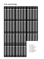
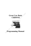
5.20. ASCII Table
Dec
Oct
Hex
Chr
Dec
Oct
Hex
Chr
Dec
Oct
Hex
0
0
1
1
2
3
Chr
0
NUL
48
60
30
0
96
140
60
`
1
S OH
49
61
31
1
97
141
61
a
2
2
S TX
50
62
32
2
98
142
62
b
3
3
ETX
51
63
33
3
99
143
63
c
4
4
4
EOT
52
64
34
4
100
144
64
d
5
5
5
EN Q
53
65
35
5
101
145
65
e
6
6
6
AC K
54
66
36
6
102
146
66
f
7
7
7
B EL
55
67
37
7
103
147
67
g
8
10
8
BS
56
70
38
8
104
150
68
h
i
9
11
9
HT
57
71
39
9
105
151
69
10
12
0A
LF
58
72
3A
:
106
152
6A
j
11
13
0B
VT
59
73
3B
;
107
153
6B
k
12
14
0C
FF
60
74
3C
<
108
154
6C
l
13
15
0D
CR
61
75
3D
=
109
155
6D
m
14
16
0E
SO
62
76
3E
>
110
156
6E
n
15
17
0F
SI
63
77
3F
?
111
157
6F
o
16
20
10
DLE
64
100
40
@
112
160
70
p
17
21
11
DC1
65
101
41
A
113
161
71
q
18
22
12
DC2
66
102
42
B
114
162
72
r
19
23
13
DC3
67
103
43
C
115
163
73
s
20
24
14
DC4
68
104
44
D
116
164
74
t
21
25
15
N AK
69
105
45
E
117
165
75
u
22
26
16
S YN
70
106
46
F
118
166
76
v
23
27
17
ETB
71
107
47
G
119
167
77
w
24
30
18
CAN
72
110
48
H
120
170
78
x
25
31
19
EM
73
111
49
I
121
171
79
y
26
32
1A
S UB
74
112
4A
J
122
172
7A
z
27
33
1B
ES C
75
113
4B
K
123
173
7B
{
28
34
1C
FS
76
114
4C
L
124
174
7C
|
29
35
1D
GS
77
115
4D
M
125
175
7D
}
30
36
1E
RS
78
116
4E
N
126
176
7E
~
31
37
1F
US
79
117
4F
O
127
177
7F
DEL
32
40
20
SP
80
120
50
P
33
41
21
!
81
121
51
Q
34
42
22
"
82
122
52
R
35
43
23
#
83
123
53
S
36
44
24
$
84
124
54
T
Dec = Decimal
37
45
25
%
85
125
55
U
Oct = Octal
38
46
26
&
86
126
56
V
Hex = Hexadecimal
39
47
27
'
87
127
57
W
Chr = Character
40
50
28
(
88
130
58
X
LF = Line Feed
41
51
29
)
89
131
59
Y
FF = Form Feed
42
52
2A
*
90
132
5A
Z
CR = Carriage R eturn
43
53
2B
+
91
133
5B
[
DEL = R ubout
44
54
2C
,
92
134
5C
\
45
55
2D
-
93
135
5D
]
46
56
2E
.
94
136
5E
^
47
57
2F
/
95
137
5F
-
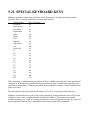
5.21. SPECIAL KEYBOARD KEYS
MMBasic generates a single unique character for the function keys and other special keys on the
keyboard. These are shown in the table as hexadecimal numbers:
Keyboard Key
Key Code (Hex)
Up Arrow
80
Down Arrow
81
Left Arrow
82
Right Arrow
83
Insert
84
Home
86
End
87
Page Up
88
Page Down
89
Alt
8B
Num Lock
8C
F1
91
F2
92
F3
93
F4
94
F5
95
F6
96
F7
97
F8
98
F9
99
F10
9A
F11
9B
F12
9C
If the control key is simultaneously pressed then 20 (hex) is added to the code (this is the equivalent of
setting bit 5). If the shift key is simultaneously pressed then 40 (hex) is added to the code (this is the
equivalent of setting bit 6). If both are pressed 60 (hex) is added. For example Control-PageDown will
generate A9 (hex).
The shift modifier only works with the function keys F1 to F12, it is ignored for the other keys.
MMBasic will translate most vt100 escape codes generated by terminal emulators such as Terra Term
and Putty to these codes (excluding the shift and control modifiers). This means that a terminal
emulator operating over a USB or a serial port opened as console will generate the same key codes as a
directly attached keyboard. This is particularly useful when using the EDIT command.
COMMANDS LISTING
ABS Function
Purpose:
To return the absolute value of the expression n.
Syntax:
ABS(n)
Comments:
n must be a numeric expression.
Examples:
PRINT ABS(7*(-5))
35
Prints 35 as the result of the action.
ASC Function
Purpose:
To return a numeric value that is the ASCII code for the first character of the string x$.
Syntax:
ASC(x$)
Comments:
If x$ is null, 0 is returned.
If x$ begins with an uppercase letter, the value returned will be within the range of 65 to 90.
If x$ begins with a lowercase letter, the range is 97 to 122.
Numbers 0 to 9 return 48 to 57, sequentially.
See the CHR$ function for ASCII-to-string conversion.
See ASCII codes appendix for ASCII codes.
Examples:
10 X$="TEN"
20 PRINT ASC(X$)
RUN
84
84 is the ASCII code for the letter T.
ATN Function
Purpose:
To return the arctangent of x, when x is expressed in radians.
Syntax:
ATN(x)
Comments:
The result is within the range of -π/2 to π/2.
The expression x may be any numeric type.
To convert from degrees to radians, multiply by π/180.
Examples:
10 INPUT X
20 PRINT ATN(X)
RUN
? 3
1.24905
Prints the arctangent of 3 radians (1.24905).
AUTO Command
Purpose:
To generate and increment line numbers automatically each time you press the ENTER key.
Syntax:
AUTO [line number][,[increment]]
Comments:
AUTO is useful for program entry because it makes typing line numbers unnecessary.
AUTO begins numbering at line number and increments each subsequent line number by
increment. The default for both values is 10.
If line number is not followed by a comma, and increment is not specified, the last increment
specified in an AUTO command is assumed.
If AUTO generates a line number that is already being used, an asterisk appears after the number to
warn that any input will replace the existing line. However, pressing ENTER immediately after the
asterisk saves the line and generates the next line number.
AUTO is terminated by entering CTRL-BREAK or CTRL-C.
Note
The line in which CTRL-BREAK or CTRL-C is entered is not saved. To be sure that you save all desired text,
use CTRL-BREAK and CTRL-C only on lines by themselves.
Examples:
AUTO 100, 50
Generates line numbers 100, 150, 200, and so on.
AUTO
Generates line numbers 10, 20, 30, 40, and so on.
CHDIR Statement
Purpose:
To change from one working directory to another.
Syntax:
CHDIR pathname$
Comments:
Pathname$ is a string expression of up to 63 characters.
To make games the working directory, type the following command:
CHDIR "GAMES"
The special entry “..” represents the parent of the current directory and “.” represents the current directory.
CIRCLE Statement
Purpose:
To draw a circle on the screen.
Syntax:
CIRCLE(xcenter, ycenter), radius[,[color][,[F]]]
Comments:
Xcenter and ycenter are the x- and y- coordinates of the center of the circle, and radius is the
radius (measured along the major axis) of the circle. The quantities xcenter and ycenter can be
expressions.
Color specifies the color of the circle. 0 draws with black color, anything different than 0 draw with
white color.
The F is fill parameter and fills the circle with the color specified in color . If the circle goes outside
the drawing area it's truncated and no error is generated.
Example 1:
10 CIRCLE(100,100), 50
Draws a circle of radius 50, centered at 100x and 100y coordinates.
20 CIRCLE(100,100), 50, 0
Erases the circle drawn with the previous command.
Example 2:
10 CLS ' This will draw 16 circles
20 FOR R=160 TO 0 STEP-10
30 CIRCLE (160,160),R,1
40 NEXT
REM Statement
Purpose:
To allow explanatory remarks to be inserted in a program.
Syntax:
REM[comment]
'[comment]
Comments:
REM statements are not executed, but are output exactly as entered when the program is listed.
Once a REM or its abbreviation, an apostrophe ('), is encountered, the program ignores everything else
until the next line number or program end is encountered.
REM statements may be branched into from a GOTO or GOSUB statement, and execution continues
with the first executable statement after the REM statement. However, the program runs faster if the
branch is made to the first statement.
Remarks may be added to the end of a line by preceding the remark with an apostrophe (') instead of
REM.
Examples:
120 REM CALCULATE AVERAGE VELOCITY
130 FOR I=1 TO 20
440 SUM=SUM+V(I)
450 NEXT I
or
129 FOR I=1 TO 20 'CALCULATED AVERAGE VELOCITY
130 SUM=SUM+V(I)
140 NEXT I
CLEAR Command
Purpose:
To set all numeric variables to zero, all string variables to null. See ERASE for deleting specific array
variables.
Syntax:
CLEAR
Comments:
The CLEAR command:
• Clears all user variables
• Resets the strings
Examples:
CLEAR
Zeroes variables and nulls all strings.
CLOSE Statement
Purpose:
To terminate input/output to a disk file or a device.
Syntax:
CLOSE #filenumber[,[#]filenumber]...]
CLOSE CONSOLE
Comments:
Filenumber is the number under which the file was opened. The association between a particular file
or device and file number terminates upon execution of a CLOSE statement. The file or device may
then be reopened using the same or a different file number. A CLOSE statement with no file number
specified will lead to error.
A CLOSE statement sent to a file or device opened for sequential output writes the final buffer of
output to that file or device.
A CLOSE CONSOLE will close the serial port which is opened for console.
Examples:
250 CLOSE #1
This closes file #1.
300 CLOSE #2, #3
Closes all files and devices associated with file numbers 2, and 3.
CLS Statement
Purpose:
To clear the screen.
Syntax:
CLS
Comments:
CLS returns the cursor to the upper-left corner of the screen
Examples:
10 CLS
This clears the screen.
CONTINUE Command
Purpose:
To continue program execution after a break.
Syntax:
CONTINE
Comments:
Resumes program execution after CTRL-BREAK, or CTRL-C . Execution continues at the point where the
break happened. If the break took place during an INPUT statement, execution continues after
reprinting the prompt.
CONTINUE is useful in debugging, in that it lets you break code, modify variables using direct
statements, continue program execution, or use GOTO to resume execution at a particular line number.
If a program line is modified, CONTINUE will be invalid.
COPYRIGHT Command
Purpose:
To print copyright message.
Syntax:
COPYRIGHT
Comments:
Print copyright message.
DATA Statement
Purpose:
To store the numeric and string constants that are accessed by the program READ statement(s).
Syntax:
DATA constants
Comments:
Constants are numeric constants in any format (fixed point, floating-point, or integer), separated by
commas. Numerical constants can also be expressions such as 5 * 60.
String constants in DATA statements must be surrounded by double quotation marks only if they
contain commas, colons, a keyword (such as THEN, WHILE, etc) or significant leading or trailing
spaces. Otherwise, quotation marks are not needed.
DATA statements are not executable and may be placed anywhere in the program. A DATA statement
can contain as many constants that will fit on a line (separated by commas), and any number of DATA
statements may be used in a program.
READ statements access the DATA statements in order (by line number). The data contained therein
may be thought of as one continuous list of items, regardless of how many items are on a line or where
the lines are placed in the program. The variable type (numeric or string) given in the READ statement
must agree with the corresponding constant in the DATA statement, or a "Type Mismatch" error
occurs.
DATA statements may be reread from the beginning by use of the RESTORE statement.
For further information and examples, see the RESTORE statement and the READ statement.
Example 1:
80 FOR I=1 TO 10
90 READ A(I)
100 NEXT I
110 DATA 3.08,5.19,3.12,3.98,4.24
120 DATA 5.08,5.55,4.00,3.16,3.37
This program segment reads the values from the DATA statements into array A. After execution, the
value of A(1) is 3.08, and so on. The DATA statements (lines 110-120) may be placed anywhere in the
program; they may even be placed ahead of the READ statement.
Example 2:
5 PRINT
10 PRINT "CITY","STATE","ZIP"
20 READ C$,S$,Z
30 DATA "DENVER,","COLORADO",80211
40 PRINT C$,S$,Z
RUN
CITY STATE ZIP
DENVER, COLORADO 80211
This program reads string and numeric data from the DATA statement in line 30.
DATE$ Statement and Variable
Purpose:
To set or retrieve the current date.
Syntax:
As a statement:
DATE$=v$
As a variable:
v$=DATE$
Comments:
The date is set to “01-01-2000” at power up. If MOD-RTC (Real-Time-Clock Module) is connected to
UEXT the current date will be set form the read content from MOD-RTC.
V$ is a valid string literal or variable.
V$ can be any of the following formats when assigning the date:
dd-mm-yy
dd/mm/yy
dd-mm-yyyy
dd/mm/yyyy
If v$ is not a valid string, a "Type Mismatch" error results. Previous values are retained.
If any of the values are out of range or missing, an "Invalid date" error is issued. Any previous date
is retained.
The current date (as assigned when the operating system was initialized) is fetched and assigned to the
string variable if DATE$ is the expression in a LET or PRINT statement.
The current date is stored if DATE$ is the target of a string assignment.
With v$=DATE$, DATE$ returns a 10-character string in the form dd-mm-yyyy. dd is the day (01 to
31), mm is the month (01 to 12) and yyyy is the year (2000 to 9999).
Examples:
V$=DATE$
PRINT V$
01-01-2000
DELETE Command
Purpose:
To delete program lines or line ranges.
Syntax:
DELETE [line number1][-line number2]
DELETE line number1Comments:
line number1 is the first line to be deleted.
line number2 is the last line to be deleted.
MM-BASIC always returns to command level after a DELETE command is executed. Unless at least
one line number is given, an "Invalid syntax" error occurs.
If the line number do not exist "Invalid line number" error occurs.
Examples:
DELETE 40
Deletes line 40.
DELETE 40-100
Deletes lines 40 through 100, inclusively.
DELETE -40
Deletes all lines up to and including line 40.
DELETE 40-
Deletes all lines from line 40 to the end of the program.
DIM Statement
Purpose:
To specify the maximum values for array variable subscripts and allocate storage accordingly.
Syntax:
DIM variable(subscripts)[,variable(subscripts)]...
Comments:
If an array variable name is used without a DIM statement, a "Array must be dimensioned
first" error occurs.
The maximum number of dimensions for an array is 8.
The minimum value for a subscript is always 0, unless otherwise specified with the OPTION BASE
statement.
An array, once dimensioned, cannot be re-dimensioned within the program without first executing a
CLEAR or ERASE statement.
The DIM statement sets all the elements of the specified arrays to an initial value of zero.
Examples:
10 DIM A(20)
20 FOR I=0 TO 20
30 READ A(I)
40 NEXT I
This example reads 21 DATA statements elsewhere in the program and assigns their values to A(0)
through A(20), sequentially and inclusively.
DO … LOOP Statement
Purpose:
To create endless loop.
Syntax:
DO
[ loop statements ]
LOOP
Comments:
This structure will loop forever; the EXIT command can be used to terminate the loop or control must
be explicitly transferred outside of the loop by commands like GOTO or RETURN (if in a subroutine).
Example:
10 DO
20 PRINT “HELLO”
30 IF INKEY$ = “q” THEN EXIT
40 LOOP
50 PRINT “DONE”
This example will print “HELLO” until “q” key is pressed.
DO WHILE ... LOOP Statement
Purpose:
To execute a series of statements in a loop, as long as a given condition is True. This is equivalent to
the old WHILE-WEND statement which is also implemented in MM-BASIC for compatibility.
Syntax:
DO WHILE expression
[loop statements]
LOOP
Comments:
If expression is nonzero (true), loop statements are executed until the LOOP statement is
encountered. MM-BASIC then returns to the DO WHILE statement and checks expression. If it is still
true, the process is repeated.
If it is not true, execution resumes with the statement following the LOOP statement.
DO WHILE and LOOP loops may be nested up to 20 times. Each LOOP matches the most recent DO
WHILE.
An unmatched LOOP statement causes a "LOOP without matching DO" error.
Example 1:
10 DO WHILE INKEY$ <> “q”
20 PRINT “HELLO”
30 LOOP
40 PRINT “DONE.”
Example 2:
90 'BUBBLE SORT ARRAY A$
100 FLIPS=1
110 DO WHILE FLIPS
115 FLIPS=0
120 FOR N=1 TO J-1
130 IF A$(N)>A$(N+1) THEN SWAP A$(N), A$(N+1): FLIPS=1
140 NEXT N
150 LOOP
DO ... LOOP UNTIL Statement
Purpose:
To execute a series of statements in a loop until a given condition is true.
Syntax:
DO
[loop statements]
LOOP UNTIL expression
Comments:
The loop statements between DO and LOOP are executed then if expression is zero (false) the
process is repeated. If it is nonzero (true), execution resumes with the statement following the LOOP
statement.
DO and LOOP UNTIL loops may be nested up to 20 times. Each LOOP matches the most recent DO.
An unmatched LOOP statement causes a "LOOP without matching DO" error.
Example:
10 DO
20 PRINT “HELLO”
30 LOOP UNTIL INKEY$ = “q”
40 PRINT “DONE.”
EDIT Command
Purpose:
Edit the line ‘line-number’.
Syntax:
EDIT line_number
EDIT
Comments:
Line_number is the number of a line existing in the program. If no line number is used this command
will edit the previous entry typed at the command prompt. If a running program has just terminated
with an error this will automatically edit the line that caused the error.
On entering the edit mode the line will be displayed, the cursor placed at the end of the line and the
editing mode set to over-type.
The editing keys are:
LEFT/RIGHT ARROWS
Moves the cursor within the line
HOME/END
Moves the cursor to the start or end of the line
DELETE
Delete the character over the cursor
BACKSPACE
Delete the character before the cursor
INSERT
Will switch between insert and overtype mode.
Use `ENTER’ to finish editing (even in insert mode). The line is added to the program just as if it had
been typed at the command prompt. If the line number had been changed a new (edited) copy of the
line will be added to memory, if it is unchanged the line will replace ‘line-number’.
When editing a program line the UP-ARROW will switch to the previous line and DOWN-ARROW to the
next line number. When doing this any changes will be automatically saved (the same as using ENTER)
before moving to the next line.
MM-BASIC is always in edit mode when entering data at the command prompt or for the INPUT and
LINE INPUT commands. In these cases the ARROW KEYS can be used to move within the line to correct
errors. If the UP-ARROW key is pressed at the command prompt it will act the same as EDIT with no line
number (edit the last error line or entered command). Subsequent UP/DOWN-ARROW presses will move
through the list of recent entries.
All the editing keys work with Terra Term and Putty (in VT100 mode) so editing can also be
accomplished over a USB or serial link using these terminal emulators or any other VT100 compatible
terminal emulator.
The maximum line length that can be edited is 79 chars in VGA mode and 49 chars in composite mode.
If more than this number of characters are entered in over-type mode MM-BASIC will automatically
enter normal text entry mode without the editing functions. If in insert mode any extra characters will
be rejected.
The current line is always the last line referenced by an EDIT statement, LIST command, or error
message.
If line number refers to a line which does not exist in the program, an "Invalid Line Number"
error occurs.
Examples:
EDIT 150
Displays program line number 150 for editing.
END Statement
Purpose:
To terminate program execution, close all files, and return to command level.
Syntax:
END
Comments:
END statements may be placed anywhere in the program to terminate execution.
An END statement at the end of a program is optional. MM-BASIC always returns to command level
after an END is executed.
END closes all files.
Example:
520 IF K>1000 THEN END ELSE GOTO 20
Ends the program and returns to command level whenever the value of K exceeds 1000.
ERASE Statement
Purpose:
To eliminate arrays from a program.
Syntax:
ERASE list of array variables
Comments:
Arrays may be re-dimensioned after they are erased, or the memory space previously allocated to the
array may be used for other purposes.
If an attempt is made to re-dimension an array without first erasing it, an error occurs.
Examples:
200 DIM B (250)
.
450 ERASE A, B
460 DIM B(3, 4)
Arrays A and B are eliminated from the program. The B array is re-dimensioned to a 3-column by 4row array (12 elements), all of which are set to a zero value.
ERROR Statement
Purpose:
To simulate the occurrence of an error, or to allow the user to define it.
Syntax:
ERROR error$
Comments:
The program execution stops and error$ is displayed as error.
Example:
The following example simulate error 15 (the code for "String too long"):
10 INPUT “Number”;a
20 INPUT “div “;b
30 IF B = 0 THEN ERROR “DIVISION BY ZERO”
40 ELSE PRINT a/b
EXIT Statement
Purpose:
Exit from DO...LOOP or FOR...NEXT statement.
Syntax:
EXIT
EXIT FOR
Comments:
The program execution will continue after the LOOP or NEXT statement.
Examples:
This example will print “HELLO” until “q” key is pressed.
10 DO
20 PRINT “HELLO”
30 IF INKEY$ = “q” THEN EXIT
40 LOOP
50 PRINT “DONE”
This example will print the numbers from 1 to 5 instead to 10
10 FOR I = 1 TO 10
20 PRINT I; “ “;
30 IF I = 5 THEN EXIT FOR
40 NEXT
FILES Command
Purpose:
List files in the current directory on the SD card.
Syntax:
FILES [search-pattern$]
Comments:
The SD card (drive B:) may use an optional search-pattern$. Question marks (?) will match any
character and an asterisk (*) as the first character of the filename or extension will match any file or
any extension. If omitted, all files will be listed.
Example:
FILES “*.BAS”
Will list all files on the SD card with .BAS extension.
FONT Statement
Purpose:
Select a font for the video output.
Syntax:
FONT [#number, [scale, [reverse]
Comments:
#number is the font number in the range of 1 to 10, the # symbol is optional.
scale is the multiply factor in the range of 1 to 8 (e.g. a scale of 2 will double the size of a pixel in
both the vertical and horizontal). Default is 1.
If reverse is a number other than zero the font will be displayed in reverse video. Default is no
reverse.
There are three fonts built into MM-BASIC:
#1
is the standard font of 10 x 5 pixels containing the full ASCII set.
#2
is a larger font of 16 x 11 pixels also with the full ASCII set.
#3
is a jumbo font of 30 x 22 pixels consisting of the numbers zero to nine and the characters
plus, minus, comma and full stop.
Other fonts can be loaded into memory, see the FONT LOAD command.
Font #1 with a scale of one and no reverse is the default on power up and will be reinstated
whenever control returns to the input prompt. So if you execute FONT statement at command
prompt there will be no font change.
Examples:
10 FONT #3,2,1
'doubles scale and reverse video of font #3
10 FONT 3,2,1
'same as above
FONT LOAD Statement
Purpose:
Will load the font contained in file and install it as font number which can be any number between 3
and 10.
Syntax:
FONT LOAD filename$ AS #fontnumber
Comments:
filename$ is file name where the font is contained..
#number is the font number in the range of 3 to 10, the # symbol is optional.
The font is loaded into the memory area used by arrays and strings, use the MEMORY command to
check the usage of this area.
A font file is just a text file containing ordinary characters which are loaded line by line to build the
bitmap of each character in the font. Each character can be up to 64 pixels high and 255 pixels wide.
Up to 255 characters can be defined.
The first non comment line in the file must be the specifications for the font as follows: height,
width, start, end
Where height and width are the size of each character in pixels, start is the number in the
ASCII chart where the first character sits and end is the last character. Each number is separated by
a comma. So, for example, 16, 11, 48, 57 means that the font is 16 pixels high and 11 wide. The
first character is decimal 48 (the zero character) and the last is 57 (number nine character).
The remainder of the lines specify the bitmap for each character.
Each line represents a horizontal row of pixels. A space means the pixel is not illuminated and any
other character will turn the pixel on. If the font is 11 pixels wide there must be 11 characters in the
line. The first line is the top row of pixels in the character, the next is the second and so on. If the
character is 16 pixels high there must be 16 lines to define the character. This repeats until each
character is drawn. Using the above example of a font 16x11 with 10 characters there must be a
total of 160 lines with each line 11 characters wide. This is in addition to the specification line at
the top.
A comment line has an apostrophe (') as the first character and can occur anywhere. A comment line
is completely ignored, all other lines are significant.
Example:
The following example creates two arrow icons, up and down arrow. Each is 11x11 pixels with the
first (up arrow) in the position of the zero character (0) and the down arrow in the position of
number one (1). To display a up arrow your program would contain this:
10 FONT LOAD “ARROWS.FNT” AS #9 'load the font
20 FONT #9
30 PRINT “0”
'EXAMPLE OF FONT FILE
'ARROWS.FNT
11,11,48,49
x
xxxxx
xxxxxxxxx
x x
x x
x x
x x
x x
xxxxx
xxxxx
x x
x x
x x
x x
x x
xxxxxxxxx
xxxxx
x
'END OF FONT
FONT UNLOAD Statement
Purpose:
Will remove font #fontnumber and free the memory used, the # symbol is optional. You cannot
unload the built in fonts.
Syntax:
FONT UNLOAD #fontnumber
Comments:
#number is the font number in the range of 3 to 10, the # symbol is optional.
IF ... THEN ... ELSE … Single line IF Statement
Purpose:
To make a decision regarding program flow based on the result returned by an expression.
Syntax:
IF expression THEN statement(s) [ELSE statement(s)]
IF expression GOTO line number
[ELSE statement(s)]
Comments:
If the result of expression is nonzero (logical true), the THEN or GOTO line number is executed.
If the result of expression is zero (false), the THEN or GOTO line number is ignored and the ELSE
line number, if present, is executed. Otherwise, execution continues with the next executable statement.
A comma is allowed before THEN and ELSE.
THEN and ELSE may be followed by either a line number for branching, or one or more statements to
be executed.
GOTO is always followed by a line number.
If the statement does not contain the same number of ELSE's and THEN's line number, each ELSE is
matched with the closest unmatched THEN. For example:
IF A=B THEN IF B=C THEN PRINT "A=C" ELSE PRINT "A < > C"
will not print "A < > C" when A < > B.
If an IF...THEN statement is followed by a line number in the direct mode, an "Invalid line
number" error results, unless a statement with the specified line number was previously entered in the
indirect mode.
Because IF ..THEN...ELSE is all one statement, the ELSE clause cannot be on a separate line. It
must be all on one line.
Example:
In the following example, a test determines if N is greater than 10 and less than 20. If N is within this
range, execution branches to line 200. If N is not within this range, execution continues with line 110.
100 IF(N<20) and (N>10) THEN 200
110 PRINT "OUT OF RANGE"
FOR ... NEXT Statements
Purpose:
To execute a series of instructions a specified number of times in a loop.
Syntax:
FOR variable=x TO y [STEP z]
[statements]
NEXT [variable][,variable...]
Comments:
Variable is used as a counter.
x,y, and z are numeric expressions.
STEP z specifies the counter increment for each loop.
The first numeric expression (x) is the initial value of the counter. The second numeric expression (y)
is the final value of the counter.
Program lines following the FOR statement are executed until the NEXT statement is encountered.
Then, the counter is incremented by the amount specified by STEP.
If STEP is not specified, the increment is assumed to be 1.
A check is performed to see if the value of the counter is now greater than the final value (y). If it is not
greater, MM-BASIC branches back to the statement after the FOR statement, and the process is
repeated. If it is greater, execution continues with the statement following the NEXT statement. This is
a FOR-NEXT loop.
The body of the loop is skipped if the initial value of the loop times the sign of the step exceeds the
final value times the sign of the step.
If STEP is negative, the final value of the counter is set to be less than the initial value. The counter is
decremented each time through the loop, and the loop is executed until the counter is less than the final
value.
Nested Loops:
FOR-NEXT loops may be nested; that is, a FOR-NEXT loop may be placed within the context of
another FOR-NEXT loop. When loops are nested, each loop must have a unique variable name as its
counter.
The NEXT statement for the inside loop must appear before that for the outside loop.
If nested loops have the same end point, a single NEXT statement may be used for all of them.
The variable(s) in the NEXT statement may be omitted, in which case the NEXT statement will
match the most recent FOR statement.
If a NEXT statement is encountered before its corresponding FOR statement, a "Cannot find a
matching FOR" error message is issued and execution is terminated.
If a NEXT variable statement is encountered before its corresponding FOR variable statement, a
"FOR without matching NEXT" error message is issued and execution is terminated.
Examples:
The following example prints integer values 1 to 10.
20 FOR I =1 TO 10 STEP 1
30 PRINT I;
40 NEXT I
RUN
1 2 3 4 5 6 7 8 9 10
In the following example, the loop does not execute because the initial value of the loop exceeds the
final value. Nothing is printed by this example.
10 R=0
20 FOR S=1 TO R
30 PRINT S
40 NEXT S
In the next example, the loop executes 10 times. The final value for the loop variable is always set
before the initial value is set.
10 S=5
20 FOR S=1 TO S+5
30 PRINT S;
40 NEXT S
RUN
1 2 3 4 5 6 7 8 9 10
In the next example, the NEXT variable is wrong and error occurs.
10 FOR I=1 TO 5
20 PRINT I;
30 NEXT S
RUN
1
Error line 30: Cannot find variable
>
GOSUB ... RETURN Statement
Purpose:
To branch to, and return from, a subroutine.
Syntax:
GOSUB line number
RETURN
Comments:
line number is the first line number of the subroutine.
A subroutine may be called any number of times in a program, and a subroutine may be called from
within another subroutine.
A RETURN statement in a subroutine causes MM-BASIC to return to the statement following the most
recent GOSUB statement. A subroutine can contain more than one RETURN statement, should logic
dictate a RETURN at different points in the subroutine.
Subroutines can appear anywhere in the program, but must be readily distinguishable from the main
program.
To prevent inadvertent entry, precede the subroutine by an END, or GOTO statement to direct program
control around the subroutine.
Examples:
10 GOSUB 40
20 PRINT "BACK FROM SUBROUTINE"
30 END
40 PRINT "SUBROUTINE";
50 PRINT " IN";
60 PRINT " PROGRESS"
70 RETURN
RUN
SUBROUTINE IN PROGRESS
BACK FROM SUBROUTINE
The END statement in line 30 prevents re-execution of the subroutine.
GOTO Statement
Purpose:
To branch unconditionally out of the normal program sequence to a specified line number.
Syntax:
GOTO line number
Comments:
line number is any valid line number within the program.
If line number is an executable statement, that statement and those following are executed. If it is a
non-executable statement, execution proceeds at the first executable statement encountered after line
number.
Examples:
10 READ R
20 PRINT "R ="; R;
30 A = 3.14*R^2
40 PRINT "AREA ="; A
50 GOTO 10
60 DATA 5, 7, 12
RUN
R = 5 AREA = 78.5
R = 7 AREA = 153.86
R = 12 AREA = 452.16
Error line 10: No more DATA to read
The "No more DATA to read" advisory is generated when the program attempts to read a fourth
DATA statement (which does not exist) in line 60.
MKDIR Command
Purpose:
To create a subdirectory.
Syntax:
MKDIR pathname$
Comments:
pathname$ is a string expression, identifying the subdirectory to be created.
Examples:
MKDIR "SALES\JOHN"
Creates the subdirectory JOHN within the directory of SALES.
NAME Command
Purpose:
To change the name of a disk file.
Syntax:
NAME oldfilename$ AS newfilename$
Comments:
oldfilename$ must exist and newfilename$ must not exist; otherwise, an error results.
After a NAME command, the file exists on the same diskette, in the same disk location, with the new
name.
Examples:
NAME "ACCTS" AS "LEDGER"
The file formerly named ACCTS will now be named LEDGER. The file content and physical location
on the diskette is unchanged. If LEDGER exist “Error: Cannot open file“ results.
NEW Command
Purpose:
To delete the program currently in memory and clear all variables.
Syntax:
NEW
Comments:
NEW is entered at command level to clear memory before entering a new program. MM-BASIC always
returns to command level after a NEW is executed.
Examples:
NEW
or
980 PRINT "Do You Wish To Quit (Y/N)
990 ANS$=INKEY$: IF ANS$=""THEN 990
1000 IF ANS$="Y" THEN NEW
1010 IF ANS$="N" THEN 980
1020 GOTO 990
ON ... GOSUB and ON ... GOTO Statements
Purpose:
To branch to one of several specified line numbers, depending on the value returned when an
expression is evaluated.
Syntax:
ON expression GOTO linenumbers
ON expression GOSUB linenumbers
Comments:
In the ON ... GOTO statement, the value of expression determines which line number in the list
will be used for branching. For example, if the value is 3, the third line number in the list will be
destination of the branch. If the value is a non-integer, the fractional portion is rounded.
In the ON ... GOSUB statement, each line number in the list must be the first line number of a
subroutine.
If the value of expression is zero or greater than the number of items in the list (but less than or
equal to 255), MM-BASIC continues with the next executable statement.
If the value of expression is negative, or greater than 255, an "Number out of range" error
occurs.
Examples:
100 IF R<1 or R>4 then print "ERROR":END
If the integer value of R is less than 1, or greater than 4, program execution ends.
200 ON R GOTO 150,300,320,390
210 PRINT “NEXT”
If R=1, the program goes to line 150.
If R=2, the program branches to line 300 and continues from there.
If R=3, the branch will be to line 320.
If R=4, the branch will be to line 390.
OPEN Statement
Purpose:
To establish input/output (I/O) to a file.
Syntax:
OPEN filename$ [FOR mode] AS [#]filenumber
Comments:
filename$ is the name of the file 8 characters max with extension .XXX max 3 characters.
mode is a string expression: OUTPUT Sequential output mode, will overwrite existing file with same
name. INPUT Sequential input mode. APPEND Sequential output mode, but from position at end of
file. If there is no existing file the APPEND option will act the same as the OUTPUT mode (i.e. the file
is created then opened for writing).
filenumber is a number between 1 and 10. The number associates an I/O buffer with a disk file or
device. This association exists until a CLOSE or CLOSE file number statement is executed.
The INPUT, LINE INPUT, PRINT, WRITE and CLOSE commands as well as the EOF() and INPUT$()
functions all use filenumber to identify the file being operated on. See also OPTION ERROR and
MM.ERRNO for error handling.
More than one file can be opened for input at one time with different file numbers. For example, the
following statements are allowed:
OPEN "TEMP.TXT" FOR INPUT AS #1
OPEN "TEMP.TXT" FOR INPUT AS #2
However, a file may be opened only once for output or appending. For example, the following
statements are illegal:
OPEN "TEMP.TXT" FOR OUTPUT AS #1
OPEN "TEMP.TXT" FOR OUTPUT AS #2
Note
Be sure to close all files before removing SD card (see CLOSE).
When a disk file is opened for APPEND, the position is initially at the end of the file. PRINT then
extends the file.
If the file is opened as INPUT, attempts to write to the file result in "Cannot find file" errors.
If the file is opened as OUTPUT, attempts to read the file result in "Cannot read from file" errors.
Opening a file for OUTPUT or APPEND fails, if the file is already open in any mode.
OPEN "COM(n) Statement
Purpose:
To allocate a buffer to support Serial asynchronous communications with other computers and
peripheral devices in the same manner as OPEN for disk files.
Syntax:
OPEN "COM[n]:[speed][,buf,FC][,OC]" AS [#]filenum
OPEN "COM[n]:[speed][,buf,FC][,OC]" AS CONSOLE
Comments:
COM[n] is a valid communications device: com1: com2: com3: com4:
com1: RX is Arduino.D2 or GPIO.13;
TX is Arduino.D3 or GPIO.14;
RTS is Arduino.D4 or GPIO.15 (if FC is used);
CTS is Arduino.D5 or GPIO.16 (if FC is used);
com2: RX is Arduino.D6 or GPIO.17;
TX is Arduino.D7 or GPIO.18;
com3: RX is UEXT.4;
TX is UEXT.3;
com4: RX is RS232.Rx if R2 is mounted also Arduino.D0 or GPIO.11;
TX is RS232.Tx if R3 is mounted also Arduino.D1 or GPIO.12;
speed is a literal integer specifying the transmit/receive baud rate. The default is 1200 bps. Note
com1: and com2: are implemented with bit-bang by MM-BASIC and maximum speed is 19200 bps,
com3: and com4: are real UARTs and maximum speed is 8 000 000 bps (speed over 115200 bps is not
reliable in practice).
FC enables flow control on com1:
filenum is a number between 1 and 10. A communications device may be opened to only one file
number at a time. If you try to open com other than com1:- com4: "Invalid syntax" error will
occur, if you try to open already opened filenumber "COMx is already open" error will occur.
When the port filenum is opened the port can be written to and read from using any commands or
functions that use a file number.
buf is the maximum number of bytes which can be read from the communications buffer default of
128 bytes.
A serial port can be opened with “AS CONSOLE”. In this case any data received will be treated the
same as keystrokes received from the keyboard and any characters sent to the video output will also be
transmitted via the serial port. This enables the remote control of MMBasic via a serial interface.
Examples:
In the following, File 1 is opened for communications with all defaults: speed at 300 bps, even parity,
seven data bits, and one stop bit.
10 OPEN "COM1:" AS 1
In the following, File 2 is opened for communications at 2400 bps. Parity and number of data bits are
defaulted.
20 OPEN "COM1:2400" AS #2
In the following, File 1 is opened for asynchronous I/O at 1200 bits/second. No parity is to be produced
or checked.
10 OPEN "COM1:1200,N,8" AS #1
OPTION BASE Statement
Purpose:
To declare the minimum value for array subscripts.
Syntax:
OPTION BASE n
Comments:
n is 1 or 0. The default base is 0.
If the statement OPTION BASE 1 is executed, the lowest value an array subscript can have is 1.
An array subscript may never have a negative value.
OPTION BASE gives an error only if you change the base value. This allows chained programs to have
OPTION BASE statements as long as the value is not changed from the initial setting.
Note
You must code the OPTION BASE statement before you can define or use any arrays. If an attempt is
made to change the option base value after any arrays are in use, an error results.
OPTION ERROR Statement
Purpose:
Sets the treatment for errors in file input/output.
Syntax:
OPTION ERROR CONTINUE
OPTION ERROR ABORT
Comments:
The option CONTINUE will cause MM-BASIC to ignore file related errors. The program must check the
variable MM.ERRNO to determine if and what error has occurred.
The option ABORT sets the normal behavior (ie, stop the program and print an error message). The
default is ABORT.
Note that this option only relates to errors reading or writing from the SD card, it does not affect the
handling of syntax and other program errors.
Examples:
In the following example if “123.TXT” exist on the SD card 0 will be printed. If “123.TXT” do not
exist will be printed 6 - “Cannot find file”
10 OPTION ERROR CONTINUE
20 OPEN "123.TXT" FOR INPUT AS #1
30 PRINT MM.ERRNO
OPTION PROMPT Statement
Purpose:
Sets the command prompt to the contents of prompt$.
Syntax:
OPTION PROMPT prompt$
Comments:
prompt$ can be an expression which will be evaluated when the prompt is printed.
Maximum length of the prompt string is 48 characters. The prompt is reset to the default (“> “) on
power up but you can automatically set it by saving the following example program as
“AUTORUN.BAS” on the internal flash drive A:.
10 OPTION PROMPT “MY PROMPT: “
20 NEW
Examples:
Next example changes the prompt as in APPLE ][:
OPTION PROMPT “]”
This is also valid prompt:
OPTION PROMPT TIME$+“ : ”
or
OPTION PROMPT CWD$+“ : ”
OPTION Fnn Statement
Purpose:
Sets the programmable function key Fnn to the contents of string$.
Syntax:
OPTION Fnn string$
Comments:
Fnn is the function key F1 to F12. Maximum string length is 12 characters.
string$ can also be an expression which will be evaluated at the time of running the OPTION
command. This is most often used to append the ENTER key (chr$(13)), or double quotes (chr$(34)).
Normally these commands should be included in an “AUTORUN.BAS” file (see OPTION PROMPT for
an example).
Examples:
OPTION F1 “RUN” + CHR$(13)
OPTION F2 “SAVE ” +CHR$(34)
PAUSE Statement
Purpose:
Will halt execution of the running program for number milliseconds.
Syntax:
PAUSE number
Comments:
The maximum value of number is 4294967295 (about 49 days).
Examples:
Next code blink LED which anode (+) is connected to Arduino.A0 and cathode (-) is connected to
GND.
10 SETPIN 1,8
20 DO
'set A0 as Digital ooutput
'do loop
30 PIN(1) = 1
'switch ON the LED
30 PAUSE 500
'wait ½ second
40 PIN(1) = 0
'switch OFF the LED
50 PAUSE 500
'wait ½ second
60 LOOP
'loop forever
PIN(nn) = Statement
Purpose:
Will halt execution of the running program for number milliseconds.
Syntax:
PIN(n) = value
Comments:
For a PIN() configured as digital output this will set the output to low if value is zero or high if
value is non zero. You can set an output high or low before it is configured as an output and that
setting will be the default output when the SETPIN command takes effect.
See the function PIN() for reading from a pin and the command SETPIN for configuring it.
Examples:
Next code blink LED which anode (+) is connected to Arduino.A0 and cathode (-) is connected to
GND.
10 SETPIN 1,8
20 DO
'set A0 as Digital ooutput
'do loop
30 PIN(1) = 1
'switch ON the LED
30 PAUSE 500
'wait ½ second
40 PIN(1) = 0
'switch OFF the LED
50 PAUSE 500
'wait ½ second
60 LOOP
'loop forever
PIXEL Statements
Purpose:
To display a point at a specified place on the screen.
Syntax:
PIXEL (x,y) = value
Comments:
(x,y) represents the coordinates of the point.
value if zero the point is with black color otherwise with white.
The function PIXEL(x,y) returns the value of a pixel with coordinates (x,y).
Coordinate values can be beyond the edge of the screen.
(0,0) is always the upper-left corner and (MM.HRES, MM.VRES) is the lower-right corner.
Example 1:
The following draws a diagonal line from (0,0) to (100,100).
10 CLS
20 FOR I=0 TO 100
30 PIXEL(I,I)=1
40 NEXT
Example 2:
The following clears out the line by setting each pixel to 0.
50 FOR I=100 TO 0 STEP -1
60 PIXEL(I,I) = 0
70 NEXT I
POKE Statement
Purpose:
To write (poke) a byte of data into a memory location.
Syntax:
POKE hiword,loword,byte
Comments:
hiword is the upper 16 bit of the memory address.
loword is the low 16 bit of the memory address.
Byte must be within the range of 0 to 255.
The PIC32 maps all control registers, flash (program) memory and volatile (RAM) memory into a
single address space. The PIC32MX7XX Family Data Sheet lists the details of this address space while
the source code will provide the symbolic names used in the firmware and the .map file (produced after
a successful compile) will list the addresses of these symbols. These addresses will change with each
version of the firmware so programs should use the predefined variable MM.VER to determine the
currently running version.
Note
This command is for expert users only.
If you use this facility to access an invalid memory address the MIPS CPU will throw an exception
which causes the processor to reset and clear all memory. To see this effect try POKE 0,0,0.
The complementary function to POKE is PEEK. The argument to PEEK is an address from which a byte
is to be read.
POKE and PEEK are useful for efficient data storage, loading assembly language subroutines, and for
passing arguments and results to and from assembly language subroutines.
PRINT Statement
Purpose:
To output a text to the screen.
Syntax:
PRINT [list of expressions][;,]
? [list of expressions][;,]
Comments:
If list of expressions is omitted, a blank line is displayed.
If list of expressions is included, the values of the expressions are displayed. Expressions in the
list may be numeric and/or string expressions, separated by commas, spaces, or semicolons. String
constants in the list must be enclosed in double quotation marks. A semicolon (;) at the end of the
expression list will suppress the automatic output of a carriage return/ newline at the end of a print
statement.
A question mark (?) may be used in place of the word PRINT.
When numbers are printed on the screen, the numbers are always followed by a space. Positive
numbers are preceded by a space. Negative numbers are preceded by a minus (-) sign. Single-precision
numbers are represented with seven or fewer digits in a fixed-point or integer format.
Integers (whole numbers) are printed without a decimal point while fractions are printed with the
decimal point and the significant decimal digits. Large numbers (greater than six digits) are printed in
scientific format.
The function FORMAT$() can be used to format numbers. The function TAB() can be used to space to
a certain column and the string functions can be used to justify or otherwise format strings.
Examples:
10 X$= “---”
20 PRINT X$"MONTHLY REPORT" X$
RUN
---MONTHLY REPORT---
The ',' will space up to 10 characters.
10 PRINT 1,2,3,4,5,6,7,8,9,10
RUN
1
10
2
3
4
5
6
7
8
9
PRINT # Statements
Purpose:
To write data to a SD card file.
Syntax:
PRINT #filenumber, list of expressions [,;]
Comments:
filenumber is the number used when the file was opened for OUTPUT or APPEND.
List of expressions consists of the numeric and/or string expressions to be written to the file.
Double quotation marks are used as delimiters for numeric and/or string expressions. The first double
quotation mark opens the line for input; the second double quotation mark closes it.
If numeric or string expressions are to be printed as they are input, they must be surrounded by double
quotation marks. If the double quotation marks are omitted, the value assigned to the numeric or string
expression is printed. If no value has been assigned, 0 is assumed. The double quotation marks do not
appear on the screen. For example:
10 PRINT #1, A
0
10 A=26
20 PRINT#1, A
26
10 A=26
20 PRINT#1, "A"
A
If double quotation marks are required within a string, use CHR$(34)(the ASCII character for double
quotation marks). For example:
100 PRINT #1,"He said,"Hello", I think"
He said, 0, I think
because the machine assigns the value 0 the variable "Hello."
100 PRINT #1, "He said, "CHR$(34) "Hello,"CHR$(34) " I think."
He said, "Hello," I think
In listofexpressions, numeric expressions must be delimited by semicolons. For example:
PRINT#1, A; B; C; X; Y; Z
If commas are used as delimiters, the extra blanks inserted between print fields will also be written to
the diskette. Commas have no effect, however, if used with the exponential format.
String expressions must be separated by semicolons in the list. To format the string expressions
correctly on the file, use explicit delimiters in listofexpressions. For example, the following:
10 A$="12345": B$="67890"
20 PRINT#1, A$, B$
gives a file image of:
12345 67890
30 PRINT#1, A$; B$
gives a file image of:
1234567890
RANDOMIZE Statement
Purpose:
To reseed the random number generator.
Syntax:
RANDOMIZE [expression]
RANDOMIZE TIMER
Comments:
If expression is omitted, MM-BASIC will generate error “Invalid syntax”
If the random number generator is not reseeded, the RND() function returns the same sequence of
random numbers each time the program is run.
To change the sequence of random numbers every time the program is run, place a RANDOMIZE
statement at the beginning of the program, and change the argument with each run. One good way to do
this is use the TIMER function.
RANDOMIZE TIMER
Examples:
10 RANDOMIZE TIMER
20 FOR I=1 to 5
30 PRINT RND(1)*100;
40 NEXT I
READ Statement
Purpose:
To read values from a DATA statement and assign them to variables.
Syntax:
READ list of variables
Comments:
A READ statement must always be used with a DATA statement.
READ statements assign variables to DATA statement values on a one-to-one basis.
READ statement variables may be numeric or string. If DATA value is string but you attempt to read
number "Expected a number" error results. The opposite is acceptable i.e. DATA value to be
number but to read it in string variable.
A single READ statement may access one or more DATA statements. They are accessed in order.
Several READ statements may access the same DATA statement.
If the number of variables in list of variables exceeds the number of elements in the DATA
statement(s), an "No more DATA to read" error occurs.
If the number of variables specified is fewer than the number of elements in the DATA statement(s),
subsequent READ statements begin reading data at the first unread element. If there are no subsequent
READ statements, the extra data is ignored.
To reread DATA statements from the start, use the RESTORE statement.
Examples:
10 DATA 1, 2, 3, “A”, ”B”, ”C”
20 READ V1, V2, V3, S1$, S2$, S3$
30 PRINT V1, V2, V3
40 PRINT S1$, S2$, S3$
RUN
1
A
2
B
3
C
10 DATA 11, 22, 33
20 READ A$, B$, C$
30 PRINT A$; B$; C$
RUN
112233
'strings are read with numbers as DATA
RENUMBER Command
Purpose:
To renumber program lines currently held in memory including all references to line numbers in
commands such as ELSE, GOTO, GOSUB, THEN, ON...GOTO, ON...GOSUB.
Syntax:
RENUMBER [first],[increment][,start]]
Comments:
first is the first line number to be used in the new sequence. The default is 10.
increment is the increment for each line. The default is 10.
start is the line number in the old program where renumbering should commence from. The default
is the first line of the program.
This command will first check for errors that may disrupt the renumbering process and it will only
change the program in memory if no errors are found. However, it is prudent to save the program
before running this command in case there are some errors that are not caught.
If a nonexistent line number appears after one of these statements ELSE, GOTO, GOSUB, THEN,
ON...GOTO, ON...GOSUB, the error message "Line number does not exist. Cancelling
RENUMBER" appears.
RENUMBER cannot be used to change the order of program lines or to create line numbers greater than
65000.
Examples:
RENUMBER
Renumbers the entire program. The first new line number will be 10. Lines increment by 10.
RENUMBER 1000,10
Renumbers the entire program. The first new line number will be 1000. Lines increment by 10.
RENUM 1000,10,200
Renumbers the lines from 200 up so they start with line number 1000 and are incremented by 10.
RESTORE Statement
Purpose:
To allow DATA statements to be reread from the start.
Syntax:
RESTORE
Comments:
After RESTORE the next READ statement accesses the first item in the first DATA statement.
Example:
10 READ A, B, C,
20 RESTORE
30 READ D, E, F
40 DATA 57, 68, 79
Assigns the value 57 to both A and D variables, 68 to B and E, and so on.
RMDIR Command
Purpose:
To delete a subdirectory.
Syntax:
RMDIR pathname$
Comments:
pathname$ is a string expression, identifying the subdirectory to be removed from its parent.
The subdirectory to be deleted must be empty of all files except "." and ".." or a "Directory not
empty" error occurs.
Example:
RMDIR "SALES"
RUN Command
Purpose:
To execute the program currently in memory, or to load a file from the SD card into memory and run it.
Syntax:
RUN [linenumber]
RUN filename$
Comments:
RUN or RUN linenumber runs the program currently in memory.
If linenumber is specified, execution begins on that line. Otherwise, execution begins at the lower
line number.
If there is no program in memory when RUN will do nothing.
RUN filename$ closes all open files and deletes the current memory contents before loading the
specified file from SD card into memory and executing it. If an extension is not specified “.BAS” will
be added to the file name.
Examples:
RUN "HELLO"
Runs HELLO.BAS .
SAVE Command
Purpose:
To save a program file the SD card.
Syntax:
SAVE filename$
Comments:
filename$ is a quoted string that follows the normal MS-DOS naming conventions i.e. 8 characters
name and 3 characters extension. If filename$ already exists, the file will be written over. If the
extension is omitted, .bas will be used.
Examples:
The following command saves the file TEST.BAS :
SAVE "TEST"
SAVEBMP Command
Purpose:
To save the current VGA or composite screen as a BMP file in the current working directory on the SD
card.
Syntax:
SAVEBMP filename$
Comments:
filename$ is a quoted string that follows the normal MS-DOS naming conventions i.e. 8 characters
name and 3 characters extension. If filename$ already exists, the file will be written over. If the
extension is omitted, .BMP will be added.
Note
Note that Windows 7 Paint has trouble displaying the image. This appears to be a bug in Paint as all
other software tested (including Windows XP Paint) can display the image without fault. To save a
program file the SD card.
Examples:
The following command saves the file IMAGE.BMP :
SAVEBMP "IMAGE"
SETPIN Statement
Purpose:
To configure external IO port .
Syntax:
SETPIN pin-number, config
SETPIN pin-number, config, line-number
Comments:
pin-number is the number of the GPIO port. It's in range 1..20 for DuinoMite-Mega, DuinoMite-
Mini and DuinoMite.
config defines how the port is configured for use.
0
Not configured or inactive
1
Analog input (reads input voltage 0-3.3V, accuracy better than ±1%)
2
Digital input (read 0 if input voltage is 0..0.65V, 1 if voltage is 2.5..3.3V/5.5V)
(5V tolerant ports are: ….)
(All digital inputs are Schmitt Trigger buffered.)
3
Frequency input
(measure frequency up to 200KHz)
4
Period input
(measure period pulse width 10nS or more)
5
Counting input
(counts pulses up to 200KHz pulse width 10nS or more)
6
Interrupt on low to high input change
(configure as digital input and interrupt is
generator on level change low to high)
7
Interrupt on high to low input change
(configure as digital input and interrupt is
generator on level change high to low)
8
Digital output (output 3.3V when 1 and 0V when 0)
(Typical current draw or sink ability on any I/O pin: 10mA)
(Maximum current draw or sink on any I/O pin: 25mA)
(Maximum current draw or sink for all I/O pins combined: 150mA)
9
Open collector digital output to 5V (0V when 0, Vcc when 1)
(Maximum open collector voltage (I/O pins 11 to 20): 5.5V )
line-number could be add only if config is 6 or 7 and configure the GPIO port to generate
interrupt on level change. line-number is the start of the interrupt routine. This mode also
configures the GPIO port as a digital input so the value of the port can always be retrieved using the
function PIN().
See also IRETURN to return from the interrupt.
See the function PIN() for reading inputs and the statement PIN()= for outputs.
Examples:
10 SETPIN 1,8
'make GPIO.1 / ARDUINO.A0 as OUTPUT
20 PIN(1) = 1
'output 3.3V to the port
30 PIN(1) = 0
'output 0V to the port
SETTICK Statement
Purpose:
To setup periodic interrupt and forward the execution to interrupt routing.
Syntax:
SETTICK period, line-number
Comments:
period is the time in milliseconds between interrupts. The period can range from 1 to 4294967295
mSec (about 49 days).
line-number is the line number of the interrupt routine. See also IRETURN to return from the
interrupt. This interrupt can be disabled by setting line-number to zero (i.e., SETTICK 0,0).
Examples:
In the following example, LED connected to GPIO.1 (ARDUINO.A0) will start blinking when “1” is
pressed and will stop when “2“ is pressed.
10 SETPIN 1,8
20 DO
'ARDUINO.A0 is output
'loop forever
30 C$=INKEY$: IF C$=”” THEN 30
'wait key pressed
40 IF C$=”1” THEN SETTICK 100,100
'set interrupt every 0.1 sec
50 IF C$=”2” THEN SETTICK 0,0: PIN(1)=0
'clear the interrupts
60 LOOP
100 IF I=0 THEN I=1: PIN(1)=1: IRETURN
110 IF I=1 THEN I=0: PIN(1)=0: IRETURN
'toggle LED
SOUND Statement
Purpose:
To generate single tone sound.
Syntax:
SOUND freq, duration, duty
Comments:
freq is the tone frequency in Hertz (cycles per second). freq is a numeric expression within the
range of 20 and 1,000,000, which corresponds to frequencies from 20Hz to 1Mhz for duration of
milliseconds. The sound is played in the background and does not stop program execution.
If duration is zero, any active SOUND statement is turned off. If no SOUND statement is running, a
duration of zero has no effect.
duty is the optional duty cycle of the waveform in percent. If it is close to zero the output will be a
narrow positive pulse, if 50 a square wave will be generated and if close to 100 it will be a very wide
positive pulse. If it is not specified the duty cycle will default to 50%.
Setting the duty cycle allows the sound output to be used as a Pulse Width Modulation (PWM) output
for driving analogue circuits. The signal will be available at the sound connector and the voltage
divider on this output should be removed so that the full signal level is available. The frequency of the
output is locked to the PIC32 crystal and is very accurate and for frequencies below 100KHz the duty
cycle will be accurate to 0.1%.
Examples:
The following example creates random sounds of short duration:
10 SOUND RND(1)*1000+100, 10
20 GOTO 10
TIME$ Statement and Variable
Purpose:
To set or retrieve the current time.
Syntax:
As a statement:
TIME$ = string exp
As a variable:
string exp=TIME$
Comments:
string exp is a valid string literal or variable that lets you set hours (hh), hours and minutes
(hh:mm), or hours, minutes, and seconds (hh:mm:ss).
hh sets the hour (0-23). Minutes and seconds default to 00.
hh:mm sets the hour and minutes (0-59). Seconds default to 00.
hh:mm:ss sets the hour, minutes, and seconds (0-59).
If string exp is not a valid string “Invalid Syntax” error will occur.
As you enter any of the above values, you may omit the leading zero, if any. You must, however, enter
at least one digit. If you wanted to set the time as a half hour after midnight, you could enter TIME$=
"0:30", but not TIME$= ":30".
If any of the values are out of range, an "Invalid time" error is issued. The previous time is
retained.
The current time is stored if TIME$ is the target of a string assignment.
The current time is fetched and assigned to the string variable if TIME$ is the expression in a LET or
PRINT statement.
If string exp = TIME$, TIME$ returns an 8-character string in the form hh:mm:ss.
The time is set to “00:00:00” at power up.
Examples:
The following example sets the time at 8:00 o'clock :
TIME$ = "08:00"
PRINT TIME$
08:00:05
TIMER= Statement and TIMER Function
Purpose:
To set the timer to a number of milliseconds.
To read TIMER value.
Syntax:
TIMER = value
var = TIMER
Comments:
TIMER = sets the TIMER to number of milliseconds. Normally this is used to reset the timer to zero,
but you can set it to any positive integer value.
TIMER function returns the elapsed time in milliseconds (e.g. 1/1000 of a second) since reset. If not
specifically reset this count will wrap around to zero after 49 days.
The timer is reset to zero on power up and you can also reset it by using TIMER = command.
TRON/TROFF Commands
Purpose:
To trace the execution of program statements.
Syntax:
TRON
TROFF
Comments:
As an aid in debugging, the TRON (trace on) command enables a trace flag that prints each line number
of the program as it is executed. The numbers appear enclosed in square brackets.
TRON may be executed in either the direct or indirect mode.
The trace flag is disabled with the TROFF (trace off) command, or when a NEW command is executed.
Examples:
TRON
10 K=10
20 FOR J=1 TO 2
30 L=K + 10
40 PRINT J; K; L
50 K=K+10
60 NEXT
70 END
RUN
[10][20][30][40] 1 10 20
[50][60][30][40] 2 20 30
[50][60][70]
TROFF
XMODEM Commands
Purpose:
To transfer a file to or from a remote computer using the XModem protocol.
Syntax:
XMODEM SEND file$
XMODEM RECEIVE file$
Comments:
Transfers a file to or from a remote computer using the XModem protocol. The transfer is done over
the USB connection or, if a serial port is opened as console, over that serial port.
file$ is the file (on the SD card or internal flash) to be sent or received.
The XModem protocol requires a cooperating software program running on the remote computer and
connected to its serial port. It has been tested on Terra Term running on Windows and it is
recommended that this be used. After running the XMODEM command in MM-BASIC select:
File -> Transfer -> XMODEM -> Receive/Send from the Terra Term menu to start the transfer.
The transfer can take up to 15 seconds to start and if the XMODEM command fails to establish
communications it will return to the MMBasic prompt after 30 seconds.
Download Terra Term from http://ttssh2.sourceforge.jp/
For Linux we recommend to use MINICOM.
Examples:
XMODEM RECEIVE “FILE.TXT”
XMODEM SEND “DATA.BAS”
CHR$ Function
Purpose:
To convert an ASCII code to its equivalent character.
Syntax:
CHR$(n)
Comments:
n is a value from 0 to 255.
CHR$ is commonly used to send a special character to the terminal or printer. For example, you could
add CHR$(13) or CHR$(34) in string.
See the ASC() function for ASCII-to-numeric conversion.
ASCII Codes are listed in page xxx.
Examples:
PRINT CHR$(66);
B
This prints the ASCII character code 66, which is the uppercase letter B.
PRINT CHR$(13);
This command prints a carriage return.
CINT Function
Purpose:
To round numbers with fractional portions to the next whole number or integer.
Syntax:
CINT(x)
Comments:
x should integer number range. See also INT() and FIX() both of which return integers.
Examples:
PRINT CINT(45.67)
46
45.67 is rounded up to 46.
PRINT CINT(-35.54)
-36
-35.54 is rounded up to -36.
COS Function
Purpose:
To return the cosine of the argument x in radians.
Syntax:
COS(x)
Comments:
x must be in radians. COS is the trigonometric cosine function. To convert from degrees to radians,
multiply by π/180.
Example 1:
10 X=2*COS(.4)
20 PRINT X
RUN
1.84212
Example 2:
10 PI=3.14159
20 PRINT COS(PI)
30 DEGREES=180
40 RADIANS=DEGREES*PI/180
50 PRINT COS(RADIANS)
RUN
-1
-1
CWD$ Function
Purpose:
To return the current working directory on the SD card as a string.
Syntax:
CWD$
Comments:
Can be used in string expression.
Example 1:
PRINT “CURRENT WORKING DIRECTORY IS: “;CWD$
CURRENT WORKING DIRECTORY IS: \
DATE$ Statement and Variable
Purpose:
To set or retrieve the current date.
Syntax:
As a statement:
DATE$=v$
As a variable:
v$=DATE$
Comments:
The internal clock/calendar will keep track of the time and date including leap years. The date is set to
“1-1-2000” on power up. To set the date use the command DATE$ =v$.
v$ is a valid string literal or variable.
v$ can be any of the following formats when assigning the date:
dd-mm-yy
dd/mm/yy
dd-mm-yyyy
dd/mm/yyyy
If v$ is not a valid string, a "Invalid syntax" error results. Previous values are retained.
DATE$ returns the current date based on MM-BASIC internal clock as a string in the form "DD-MM-
YYYY". For example, “26-06-2011”.
With v$=DATE$, DATE$ returns a 10-character string in the form dd-mm-yyyy.
dd is the day (01 to 31), mm is the month (01 to 12) and yyyy is the year (2000 to 9999).
Examples:
v$=DATE$
PRINT V$
01-12-2011
EOF Function
Purpose:
To return true if the end of file has been reached, or to return 0 if end of file (EOF) has not been found.
Syntax:
v=EOF([#]file-number)
Comments:
Will return true if the file previously opened for INPUT with the file-number is positioned at the
end of the file.
If used on a file-number opened as a serial port this function will return true if there are no
characters waiting in the receive buffer.
The # is optional. Also see the OPEN, INPUT and LINE INPUT commands and the INPUT$ function.
Examples:
10 OPEN "COM1:19200" AS #5
20 IF NOT EOF(#5) THEN PRINT INPUT$(1,#5);
30 GOTO 20
Open the COM1 serial port and if character is received in the buffer print it on the screen.
EXP Function
Purpose:
To return e (the base of natural logarithms) to the power of x.
Syntax:
EXP(x)
Comments:
X must not cause overflow.
Examples:
10 X = 5
20 PRINT EXP(X-1)
RUN
54.5981
Prints the value of e to the 4th power.
FIX Function
Purpose:
To truncate x to a whole number.
Syntax:
FIX(x)
Comments:
FIX does not round off numbers, it simply eliminates the decimal point and all characters to the right
of the decimal point.
FIX(x) is equivalent to SGN(x)*INT(ABS(x)). The major difference between FIX and INT is that
FIX does not return the next lower number for negative x. This behavior is for Microsoft
compatibility.
FIX is useful in modulus arithmetic.
See also CINT() .
Examples:
PRINT FIX(9.89)
9
PRINT FIX(-2.11)
-2
FORMAT$ Function
Purpose:
To return a string representing number formatted according to the specifications in the string
format$.
Syntax:
FORMAT$(number, format$)
Comments:
The format$ specification starts with a % character and ends with a letter. Anything outside of this
construct is copied to the output as is.
The structure of a format specification is:
% [flags] [width] [.precision] type
Where flags can be:
-
Left justify the value within a given field width
0
Use 0 for the pad character instead of space
+
Forces the + sign to be shown for positive numbers
space Causes a positive value to display a space for the sign. Negative values still show
the – sign
width is the minimum number of characters to output, less than this the number will be padded, more
than this the width will be expanded.
precision specifies the number of fraction digits to generate with an e, or f type or the maximum
number of significant digits to generate with a g type. If specified the precision must be preceded by a
dot (.).
type can be one of:
g
Automatically format the number for the best presentation.
f
Format the number with the decimal point and following digits
e
Format the number in exponential format
If uppercase G or F is used the exponential output will use an uppercase E. If the format specification is
not specified “%g” is assumed.
Examples:
format$(45) will return 45
format$(45,”%g”) will return 45
format$(24.1,”%g”) will return 24.1
format$(24.1,”%f”) will return 24.100000
format$(24.1,”%e”) will return 2.410000e+01
format$(24.1,”%09.3f”) will return 00024.100
format$(24.1,”%+.3f”) will return +24.100
format$(24.1,”**%-9.3f**”) will return **24.100
**
HEX$ Function
Purpose:
To return a string which represents the hexadecimal value of the numeric argument.
Syntax:
v$=HEX$(x)
Comments:
HEX$ converts decimal values within the range of ±1677100 string expression within the range of 0 to
FFFFFFFF.
Hexadecimal numbers are numbers to the base 16, rather than base 10 (decimal numbers).
x is rounded to an integer before HEX$(x) is evaluated.
If x is negative, 2's (binary) complement form is used i.e. -1 is FFFFFFFF
Example:
10 CLS: INPUT "INPUT DECIMAL NUMBER";X
20 A$=HEX$(X)
30 PRINT X "DECIMAL IS "A$" HEXADECIMAL"
RUN
INPUT DECIMAL NUMBER? 32
32 DECIMAL IS 20 HEXADECIMAL
INKEY$ Variable
Purpose:
To return one character read from the keyboard.
Syntax:
v$=INKEY$
Comments:
If no character is pending in the keyboard buffer, a null string (length zero) is returned.
If several characters are pending, only the first is returned.
No characters are displayed on the screen, and all characters except the following are passed to the
program:
CTRL-BREAK
CTRL-NUM LOCK
CTRL-ALT-DEL
CTRL-PRTSCR
PRTSCR
Example:
10 CLS
'game moves rectangle on the screen 1,2,3 keys are used
20 X = 0 : D = 1
30 LINE (X*20,100)-(X*20+20,105),1,BF
40 PAUSE 100
50 LINE (X*20,100)-(X*20+20,105),0,BF
60 C$ = INKEY$
70 IF C$ = “1” THEN D = -1 'move right to left
80 IF C$ = “2” THEN D = 1
'move left to right
90 IF C$ = “3” THEN END
'quit
100 X = X + D
110 IF X > 23 THEN X = 0
120 IF X < 0 THEN X = 23
130 GOTO 30
INPUT$() Function
Purpose:
To read and return characters from file.
Syntax:
v$=INPUT$(number, [#]file-number)
Comments:
Will return a string composed of number characters read from a file previously opened for INPUT
with the file number file-number. This function will read all characters including carriage return and
new line without translation.
When reading from a serial communications port this will return as many characters as are waiting in
the receive buffer up to number. If there are no characters waiting it will immediately return with an
empty string.
The # is optional. Also see the OPEN command.
Examples:
In the following example, MOD-GPS is connected to DuinoMite-Mega UEXT and the GPS message in
NMEA format is read and will display it on the screen.
10 OPEN “COM3:19200” AS #3
20 PRINT INPUT$(1,#3);
30 GOTO 20
INSTR Function
Purpose:
To search for the first occurrence of string y$ in x$, starting from position n and return the position at
which the string is found.
Syntax:
INSTR([n,]x$,y$)
Comments:
Optional offset n sets the position for starting the search. The default value for n is 1. If n equals
zero, the error message "Number out of bounds" is returned. n must be within the range of 1 to
255. If n is out of this range, an "Number out of bounds" error is returned.
INSTR returns 0 if:
• n > LEN(x$)
• x$ is null
• y$ cannot be found
If y$ is “”, INSTR returns n.
x$ and y$ may be string variables, string expressions, or string literals.
Examples:
10 X$="ABCDEBXYZ"
20 Y$="B"
30 PRINT INSTR(X$, Y$); INSTR(4, X$, Y$)
RUN
2 6
The interpreter searches the string "ABCDFBXYZ" and finds the first occurrence of the character B at
position 2 in the string. It then starts another search at position 4 (D) and finds the second match at
position 6 (B). The last three characters are ignored, since all conditions set out in line 30 were
satisfied.
INT Function
Purpose:
To truncate an expression to a whole number.
Syntax:
INT(n)
Comments:
Negative numbers return the next lowest number. This behaviour is for Microsoft compatibility, the
FIX() function provides a true integer function.
The FIX and CINT functions also return integer values.
Examples:
PRINT INT(98.89)
98
PRINT INT(-12.11)
-13
LEFT$ Function
Purpose:
To return a string that comprises the left-most n characters of x$.
Syntax:
LEFT$(x$,n)
Comments:
n must be within the range of 0 to 255. If n is greater than LEN(x$), the entire string (x$) will be
returned. If n equals zero, the null string (length zero) is returned (see the MID$() and RIGHT$()
substring functions).
Example:
10 A$="BASIC"
20 B$=LEFT$(A$, 3)
30 PRINT B$
RUN
BAS
The left-most three letters of the string "BASIC" are printed on the screen.
LEN FUNCTION
Purpose:
To return the number of characters in x$.
Syntax:
LEN(x$)
Comments:
x$ is any string expression. Non-printing characters and blanks are counted.
Example:
10 X$="PORTLAND, OREGON"
20 PRINT LEN(X$)
RUN
16
Note that the comma and space are included in the character count of 16.
LOC Function
Purpose:
To return the number of bytes waiting in the receive buffer of a serial port (ie, COM1:, COM2:, COM3:
or COM4:).
Syntax:
LOC([#]file-number)
Comments:
file-number is the file number used when the Serial port was opened. The # is optional.
When transmitting or receiving a file through a communication port, LOC returns the number of
characters in the input buffer waiting to be read. The default size for the input buffer is 127 characters.
If there are more than 127 characters received only the last 127 remain in the buffer, LOC returns 127.
If fewer than 127 characters remain in the buffer, then LOC returns the actual count.
Examples:
200 IF LOC(#1)>5 THEN 300
'process the input message when 5 are read
The program jumps to line 300 after 5 characters are read.
LOF Function
Purpose:
To return the free space in the transmit buffer.
Syntax:
LOF([#]file-number)
Comments:
file-number is the number of the file that the file was opened under.
With communications files, LOF returns the amount of free space in the input buffers.
Examples:
The following example reads message only when the buffer is half filled:
10 OPEN "COM1:9600" AS #1
20 IF LOF(#1) > 64 THEN MSG$=INPUT$(64,#1)
LOG Function
Purpose:
To return the natural logarithm of x.
Syntax:
LOG(x)
Comments:
x must be a number greater than zero.
Examples:
PRINT LOG(2)
.693147
PRINT LOG(1)
0
PRINT LOG(0.0001)
-9.21034
LCASE$ Function
Purpose:
To return x$ converted to lowercase characters.
Syntax:
LCASE$(x$)
Comments:
x$ may be empty string.
Example:
PRINT LCASE$(“qWeRTyUIop”)
qwertyuiop
MID$ Function
Purpose:
To return a string of m characters from x$ beginning with the nth character.
Syntax:
MID$(x$,n[,m])
Comments:
n must be within the range of 1 to 255.
m must be within the range of 0 to 255.
If m is omitted, or if there are fewer than m characters to the right of n, all rightmost characters
beginning with n are returned.
If n > LEN(x$), MID$ function returns a null string.
If m equals 0, the MID$ function returns a null string.
If either n or m is out of range, an "Number out of bounds" is returned.
Example:
10 A$="GOOD"
20 B$="MORNING EVENING AFTERNOON"
30 PRINT A$; MID$(B$, 8, 8)
RUN
GOOD EVENING
Line 30 concatenates (joins) the A$ string to another string with a length of eight characters, beginning
at position 8 within the B$ string.
OCT$ Function
Purpose:
To convert a decimal value to an octal value.
Syntax:
OCT$(x)
Comments:
x is rounded to an integer before OCT$(x) is evaluated.
OCT$ converts decimal values within the range of ±1677100 to an octal string expression.
Octal numbers are numbers to the base 8 rather than base 10 (decimal numbers).
See the HEX$ function for hexadecimal conversion.
Examples:
10 PRINT OCT$(18)
RUN
22
Decimal 18 equates to Octal 22.
PEEK Function
Purpose:
To read from a specified memory location.
Syntax:
PEEK(hiword,loword)
Comments:
Returns the byte (decimal integer within the range of 0 to 255) read from the specified memory
location. hiword is the top 16 bits of the address while loword is the bottom 16 bits.
See the POKE command for notes and warnings related to memory access.
PEEK is the complementary function to the POKE statement.
PIN() Function
Purpose:
To read from a specified external GPIO port.
Syntax:
PIN(n)
Comments:
If the GPIO ports is initialized as Digital Input with the SETPIN command, zero means digital low,
read 1 means digital high.
For GPIO ports initialized with SETPIN command as analogue inputs, it will return the measured
voltage as a floating point number between 0 and 3.3 which corresponds to 0V to 3.3V.
For GPIO ports initialized with SETPIN command as Frequency inputs, will return the frequency in Hz
(maximum 200KHz).
For GPIO ports initialized with SETPIN command as Period inputs, will return the period in
milliseconds.
For GPIO ports initialized with SETPIN command as Count input, will return the count since reset
(counting is done on the positive rising edge). The count input can be reset to zero by resetting the pin
to counting input (even if it is already so configured).
PIN(0) is a special case which will always return the state of the user push button on the PC board
(non zero means that the button is down).
Also see the SETPIN and PIN()= commands.
Example:
In the following example, a LED connected to ARDUINO.A0 and GND will light ON when User
button is pressed.
10 SETPIN 1,8
20 PIN(1) = PIN(0)
30 GOTO 20
POS Function
Purpose:
To return the current cursor position.
Syntax:
POS
Comments:
The leftmost position is 1.
Example:
10 CLS
20 A$ = INKEY$ :IF A$ = "" THEN GOTO 30 ELSE PRINT A$;
40 IF POS > 10 THEN PRINT CHR$(13);CHR$(10);
50 GOTO 30
Causes a carriage return and line feed after the 10th character is printed on each line of the screen.
PIXEL Function
Purpose:
To return the current value of a pixel on the VGA or composite screen.
Syntax:
PIXEL(x,y)
Comments:
Zero is off, 1 is on. Most upper-left coordinate is 0,0 the most right-down coordinates are
MM.HRES,MM.VRES.
See the statement PIXEL(x,y)= for setting the value of a pixel.
Example:
CLS
PRINT PIXEL(100,100)
0
RIGHT$ Function
Purpose:
To return the rightmost n characters of string x$.
Syntax:
RIGHT$(x$,n)
Comments:
If n is equal to or greater than LEN(x$), RIGHT$ returns x$. If n equals zero, the null string (length
zero) is returned (see the MID$ and LEFT$ functions).
Example:
10 A$="DISK BASIC"
20 PRINT RIGHT$(A$, 5)
RUN
BASIC
Prints the rightmost five characters in the A$ string.
RND Function
Purpose:
To return a random number between 0 and 0.99999.
Syntax:
RND[(x)]
Comments:
The same sequence of random numbers is generated each time the program is run unless the random
number generator is reseeded (see RANDOMIZE statement).
x value is ignored if supplied.
To get a random number within the range of zero through n, use the following formula:
INT(RND*(n+1))
Examples:
PRINT RND
0.513871
PRINT RND (1)
'prints two numbers due to the space between RND and (
0.175726 1
PRINT RND(-1)
0.94763
PRINT INT(RND*101)
53
'prints random number 0 – 100
SGN Function
Purpose:
To return the sign of x.
Syntax:
SGN(x)
Comments:
x is any numeric expression.
If x is positive, SGN(x) returns 1.
If x is 0, SGN(x) returns 0.
If x is negative, SGN(x) returns -1.
Examples:
10 INPUT "Enter value", x
20 ON SGN(X)+2 GOTO 100, 200, 300
MM-BASIC branches to 100 if X is negative, 200 if X is 0, and 300 if X is positive.
SIN Function
Purpose:
To calculate the trigonometric sine of x, in radians.
Syntax:
SIN(x)
Comments:
To obtain SIN(x) when x is in degrees, use SIN(x*π/180).
Examples:
PRINT SIN(1.5)
0.997495
The sine of 1.5 radians is 0.997495.
SPACE$ Function
Purpose:
To return a string of x spaces.
Syntax:
SPACE$(x)
Comments:
x is rounded to an integer and must be within the range of 0 to 255. If the number is outside this range
error “Number out of bounds“ results.
Example:
10 FOR N=1 TO 5
20 X$=SPACE$(N)
30 PRINT X$; N
40 NEXT N
RUN
1
2
3
4
5
Line 20 adds one space for each loop execution.
SPC Function
Purpose:
To skip a specified number of spaces in a PRINT.
Syntax:
SPC(n)
Comments:
n must be within the range of 0 to 255.
If n is greater than the defined width of the printer or the screen, the value used will be n MOD width.
This function is similar to the SPACE$() function and is only included for Microsoft compatibility.
Examples:
PRINT "OVER" SPC(15) "THERE"
OVER
THERE
SPI Command
Purpose:
To send and receive a byte using SPI protocol.
Syntax:
SPI(rx, tx, clock, data, speed)
Comments:
MM-BASIC is the master (i.e. it generates the clock).
rx is the GPIO port number for the data input (aka MISO master-input slave-output)
tx is the GPIO port number for the data output (aka MOSI master-output slave-input)
clock is the GPIO port number for the clock generated by MM-MASIC (aka CLK)
data is optional and is an integer representing the data byte to send over the data output pin. If it is not
specified the tx pin will be held low as if the data is 0.
speed is optional and is the speed of the clock. It is a single letter either H, M or L where H is 500KHz,
M is 50KHz and L is 5KHz. Default is H.
Examples:
10 SETPIN 1,2
'define Rx as input
20 SETPIN 2,8
'define Tx as output
30 SETPIN 3,8
'define clock as output
40 PRINT SPI(1,2,3,255,H)
RUN
255
'send FF and receive one byte
SQR Function
Purpose:
Returns the square root of x.
Syntax:
SQR(x)
Comments:
x must be greater than or equal to 0.
Example:
10 FOR X=10 TO 25 STEP 5
20 PRINT X; SQR(X)
30 NEXT
RUN
10 3.16228
15 3.87298
20 4.47214
25 5
STR$ Function
Purpose:
To return a string representation of the decimal (base 10) value of x.
Syntax:
STR$(x)
Comments:
STR$(x) is the complementary function to VAL(x$).
Examples:
10 INPUT "TYPE A NUMBER: ", N
20 PRINT “THIS IS A”;LEN(STR$(N));” DIGIT NUMBER”
> RUN
TYPE A NUMBER: 123
THIS IS A 3 DIGIT NUMBER
STRING$ Function
Purpose:
To return
• a string of length n whose characters all have ASCII code j, or
• the first character of x$
Syntax:
STRING$(n,j)
STRING$(n,x$)
Comments:
STRING$ is also useful for printing top and bottom borders on the screen.
n and j are integer expressions in the range 0 to 255.
Example:
10 X$ = STRING$(10, 45)
20 PRINT X$ "MONTHLY REPORT" X$
RUN
----------MONTHLY REPORT----------
45 is the decimal equivalent of the ASCII symbol for the minus (-) sign.
TAB Function
Purpose:
Spaces to position n on the screen.
Syntax:
TAB(n)
Comments:
If the current print position is already beyond space n, TAB goes to that position on the next line.
Space 1 is the leftmost position. The rightmost position is the screen width.
n must be within the range of 1 to 255.
It is as though the TAB function has an implied semicolon after it.
TAB may be used only PRINT or PRINT # statements.
Examples:
10 PRINT "HELLO" TAB(3) "WORLD"
RUN
HELLO
WORLD
10 PRINT “HELLO” TAB(10) “WORLD”
RUN
HELLO
WORLD
TAN Function
Purpose:
To calculate the trigonometric tangent of x, in radians.
Syntax:
TAN(x)
Comments:
To obtain TAN(x) when x is in degrees, use TAN(x*pi/180).
Examples:
10 Y = TAN(X)
When executed, Y will contain the value of the tangent of X radians.
UCASE$ Function
Purpose:
To return x$ converted to uppercase characters.
Syntax:
UCASE$(x$)
Comments:
x$ may be empty string.
Examples:
PRINT UCASE$(“qWeRTyUIop”)
QWERTYUIOP
VAL Function
Purpose:
Returns the numerical value of string x$.
Syntax:
VAL(x$)
Comments:
The VAL function also strips leading blanks, tabs, and line feeds from the argument string. For example,
the following line returns -3:
VAL(" -3")
The STR$ function (for numeric to string conversion) is the complement to the VAL(x$) function.
If the first character of x$ is not numeric, the VAL(x$) will return zero.
This function will recognize the &H prefix for a hexadecimal number, &O for octal and &B for binary.
Example:
10 INPUT “ENTER ZIP:”; ZIP$
20 IF VAL(ZIP$)<1000 OR VAL(ZIP$)>9000 THEN PRINT "INVALID ZIP"
30 IF VAL(ZIP$) = 4000 THEN PRINT “THIS IS THE ZIP POST CODE FOR THE CITY
OF PLOVDIV WHERE DUINOMITE WAS BORN :)”
IF ... THEN ... ELSE/ELSEIF...ENDIF Multi line IF Statement
Purpose:
To make a decision regarding program flow based on the result returned by an expression.
Syntax:
IF expression THEN
statement(s)
[ELSE
statement(s)]
[ENDIF]
IF expression THEN
statement(s)
[ELSEIF expression THEN
statement(s)]
[ENDIF]
Comments:
If the result of expression is nonzero (logical true), the statements after THEN are executed,
otherwise the statements after ELSE are executed.
THEN and ELSE may be followed by either a line number for branching, or one or more statements to
be executed.
Example:
In the following example, a test determines if N is greater than 10 and less than 20. If N is within this
range, execution branches to line 200. If N is not within this range, execution continues with line 110.
100 FOR A = 3 TO 7
110 PRINT A
120 IF A < 5 THEN
130 PRINT "A < 5"
140 ELSEIF A = 5 THEN
150 PRINT "A = 5"
160 ELSE
170 PRINT "A > 5"
180 ENDIF
190 NEXT
LINE INPUT Statement
Purpose:
To input an entire line (up to 255 characters) from the keyboard into a string variable, ignoring
delimiters.
Syntax:
LINE INPUT [prompt$] [;] [,] string-variable
Comments:
prompt$ is a string literal, displayed on the screen, that allows user input during program execution.
A question mark is not printed no matter if the delimiter is [;] or [,] unless it is part of prompt$.
String-variable accepts all input from the end of the prompt to the carriage return. Trailing blanks
are not ignored.
LINE INPUT is almost the same as the INPUT statement, except that it accepts special characters
(such as commas) in operator input during program execution.
If a line-feed/carriage return sequence (this order only) is encountered, both characters are input and
echoed. Data input continues.
A LINE INPUT may be escaped by typing CTRL-BREAK. MM-BASIC returns to command level and
displays '>'.
Typing CONT resumes execution after the LINE INPUT line.
Example:
100 LINE INPUT A$
Program execution pauses at line 100, and all keyboard characters typed thereafter are input to string
A$ until ENTER, CTRL-M, CTRL-C, or CTRL-BREAK is entered.
LINE INPUT # Statement
Purpose:
To read an entire line (up to 255 characters), without delimiters, from a sequential disk file to a string
variable.
Syntax:
LINE INPUT #filenumber, string-variable
Comments:
Filenumber is the number under which the file was opened.
string-variable is the variable name to which the line will be assigned.
LINE INPUT # reads all characters in the sequential file up to a carriage return. If a line feed/carriage
return sequence (this order only) is encountered, it is input.
LINE INPUT # is especially useful if each line of a data file has been broken into fields, or if a
BASIC program saved in ASCII mode is being read as data by another program.
Example:
10 OPEN "INFO.TXT" AS OUTPUT #1
20 LINE INPUT "CUSTOMER INFORMATION?"; C$
30 PRINT #1, C$
40 CLOSE #1
50 OPEN "INFO.TXT" AS INPUT #1
60 LINE INPUT #1, C$
70 PRINT C$
80 CLOSE #1
RUN
CUSTOMER INFORMATION?
If the operator enters
LINDA JONES 234, 4 MEMPHIS
then the program continues with the following:
LINDA JONES 234, 4 MEMPHIS
LIST Command
Purpose:
To list all or part of a program to the screen, line printer, or file.
Syntax:
LIST [linenumber][-linenumber]
LIST [linenumber-]
Comments:
linenumber is a valid line number within the range of 0 to 65000.
Use the hyphen to specify a line range. If the line range is omitted, the entire program is listed.
linenumber- lists that line and all higher numbered lines. -linenumber lists lines from the
beginning of the program through the specified line.
Any listing may be interrupted by pressing CTRL-BREAK. If the lines are more than size of the screen the
list will display first lines then “PRESS ANY KEY ...” message will be displaying and listing will
continue after key is pressed for the next screen of lines.
Examples:
LIST
Lists all lines in the program.
LIST -20
Lists lines 1 through 20.
LIST 10-20
Lists lines 10 through 20.
LIST 20-
Lists lines 20 through the end of the program.
LOAD Command
Purpose:
To load a file from diskette into memory.
Syntax:
LOAD filename$
Comments:
filename$ is the filename used when the file was saved. If the extension was omitted, .BAS will be
used.
LOAD closes all open files and deletes all variables and program lines currently residing in memory
before it loads the designated program. Second " could be omited.
Examples:
LOAD "DEMO
Loads the file DEMO.BAS .
LOCATE Statement
Purpose:
To move the cursor to the specified X,Y pixel position on the screen. Subsequent PRINT command will
place its output at this location
Syntax:
LOCATE X,Y
Comments:
X is the horizontal pixel position with value from 0 to MM.HRES.
Y is the vertical pixel position with value from 0 to MM.VRES.
If X value is over MM.HRES X will be assigned to 0.
If Y value is over MM.VRES Y will be assigned to MM.VRES.
Example:
10 LOCATE 100,100
20 PRINT “HI” ' print HI on position 100,100
MEMORY Command
Purpose:
List the amount of memory currently in use.
Syntax:
MEMORY
Comments:
Program memory is cleared by the NEW command. Variable, array and string memory spaces are cleared
by many commands (eg, NEW, RUN, LOAD, etc) as well as the specific commands CLEAR and ERASE.
Example:
>MEMORY
5kB
(17%) Program memory used
3kB
(16%) Variable memory used
12kB (30%) Array and string memory used
>
MERGE Command
Purpose:
Adds program lines from filename$ to the program in memory. Unlike LOAD, it does not clear the
program currently in memory.
Syntax:
MERGE filename$
Comments:
filename$ is a valid string expression containing the filename. If no extension is specified, then
MM-BASIC assumes an extension of .BAS.
The SD card is searched for the named file. If found, the program lines on the SD card are merged with
the lines in memory. After the MERGE command, the merged program resides in memory, and MMBASIC returns to the direct mode.
If any line numbers in the file have the same number as lines in the program in memory, the lines from
the file replace the corresponding lines in memory.
Examples:
MERGE "CODE.BAS"
Merges the file code.bas with the program currently in memory, provided code.bas was previously
saved.
INPUT Statement
Purpose:
To prepare the program for input from the terminal during program execution.
Syntax:
INPUT [prompt string;] list of variables
INPUT [prompt string,] list of variables
Comments:
prompt string is a request for data to be supplied during program execution.
list of variables contains the variable(s) that stores the data in the prompt string.
Each data item in the prompt string must be surrounded by double quotation marks, followed by a
semicolon or comma and the name of the variable to which it will be assigned. If more than one
variable is given, data items must be separated by commas.
The data entered is assigned to the variable list. The number of data items supplied must be the same as
the number of variables in the list.
The variable names in the list may be numeric or string variable names (including subscripted
variables). The type of each data item input must agree with the type specified by the variable name.
If more than the list of variables is entered only the first are used and the extra inputs are ignored.
INPUT A,B,C
? 1,2,3,4,5
will assign A=1 B=2 C=3 and the 4 and 5 entries will be ignored
If the variable is number but string is entered then 0 will be assigned to the variable
INPUT A,B,C
? 1,hi
will assign A=1 B=0 C=0
A comma may be used instead of a semicolon after prompt string to suppress the question mark. For
example, the following line prints the prompt with no question mark:
INPUT "ENTER BIRTHDATE",B$
When an INPUT statement is encountered during program execution, the program halts, the prompt
string is displayed, and the operator types in the requested data. When the operator presses the ENTER
key, program execution continues.
Example 1:
To find the square of a number:
10 INPUT X
20 PRINT X "SQUARED IS" X^2
30 END
RUN
?
The operator types a number (5) in response to the question mark.
5 SQUARED IS 25
Example 2:
To find the area of a circle when the radius is known:
10 PI=3.14
20 INPUT "WHAT IS THE RADIUS"; R
30 A=PI*R^2
40 PRINT "THE AREA OF THE CIRCLE IS"; A
50 PRINT
60 GOTO 20
RUN
WHAT IS THE RADIUS? 7.4
THE AREA OF THE CIRCLE IS 171.9464
INPUT #filenumber Statement
Purpose:
To read data items from a sequential file and assign them to program variables.
Syntax:
INPUT #filenumber, variable list
Comments:
file number is the number used when the file was opened for input.
variable list contains the variable names to be assigned to the items in the file.
The data items in the file appear just as they would if data were being typed on the keyboard in
response to an INPUT statement.
The variable type must match the type specified by the variable name.
With INPUT #, no question mark is printed, as it is with INPUT.
Numeric Values
For numeric values, leading spaces and line feeds are ignored. The first character encountered (not a
space or line feed) is assumed to be the start of a number. The number terminates on a space, carriage
return, line feed, or comma.
Strings
If MM-BASIC is scanning the sequential data file for a string, leading spaces and line feeds are
ignored.
If the first character is a double quotation mark ("), the string will consist of all characters read
between the first double quotation mark and the second. A quoted string may not contain a double
quotation mark as a character. The second double quotation mark always terminates the string.
If the first character of the string is not a double quotation mark, the string terminates on a comma,
carriage return, line feed, or after 255 characters have been read.
If end of the file is reached when a numeric or string item is being INPUT, the item is terminated.
IRETURN Statement
Purpose:
To return from a interrupt.
Syntax:
IRETURN
Comments:
The IRETURN statement causes MM-BASIC to branch back to the statement where interrupt occurs. A
subroutine may contain more than one IRETURN statement to return from different points in the
subroutine. Subroutines may appear anywhere in the program.
KILL Command
Purpose:
To delete a file from a disk.
Syntax:
KILL filename$
Comments:
filename$ can be a program file or data file.
KILL is used for all types of disk files.
Note
You must specify the filename's extension when using the KILL command. Remember that files saved
in MM-BASIC are given the default extension .BAS.
If a KILL command is given for a file that is currently open, no error will occurs.
Examples:
The following command deletes the MM-BASIC file DATA1, and makes the space available for
reallocation to another file:
200 KILL "DATA1.BAS"
The following command deletes the MM-BASIC file RAINING from the subdirectory dogs:
KILL "CATS\DOGS\RAINING.BAS"
LET Statement
Purpose:
To assign the value of an expression to a variable.
Syntax:
[LET] variable=expression
Comments:
The word LET is optional; that is, the equal sign is sufficient when assigning an expression to a
variable name.
The LET statement is seldom used. It is included here to ensure compatibility with previous versions of
BASIC that require it.
When using LET, remember that the type of the variable and the type of the expression must match. If
they don't, an error occurs.
A = “Hello”
Error: Expected a number
Example 1:
The following example lets you have downward compatibility with an older system. If this downward
compatibility is not required, use the second example, as it requires less memory.
110 LET D=12
120 LET E=12^2
130 LET F=12^4
140 LET SUM=D+E+F
Example 2:
110 D=12
120 E=12^2
130 F=12^4
140 SUM=D+E+F
LINE Statement
Purpose:
To draw lines and boxes on the screen.
Syntax:
LINE [(x1,y1)]-(x2,y2) [,[color][,B[F]]
Comments:
x1,y1 and x2,y2 specify the end points of a line.
color draw with white if nonzero
B (box) draws a box with the points (x1,y1) and (x2,y2) at opposite corners.
BF (filled box) draws a box (as ,B) and fills in the interior with points.
Note
If x1,y1 is not specified last x,y coordinates are used.
LINE (100,100)-(200,200),1,BF
'draw box 100,100,200,200
LINE -(300,100),1,BF
'draw box 200,200,300,100
Examples:
LINE (MM.HRES \2,0)-(MM.HRES \2,MM.VRES)
Draws a vertical line which divides the screen in half from top to bottom.
LINE (0,MM.VRES \2)-(MM.HRES,MM.VRES \2)
Draws a horizontal line which divides the screen in half from left to right.
LINE (0,0)-(MM.HRES,MM.VRES)
Draws a diagonal line from the top left to lower right corner of the screen.
LINE (10,10)-(20,20),1
Draws a line from 10,10 to 20,20 with white color.
LINE (10,10)-(20,20),0
Draws a line from 10,10 to 20,20 with black color (erases the line drawn above).
10 CLS
20 LINE -(RND(1)*MM.HRES,RND(1)*MM.VRES)
30 PAUSE RND(1)*100
40 GOTO 20
Draw random lines with random speed.
10 CLS
20 FOR I = 1 TO MM.HRES STEP 5
30 LINE (0,0)-(I,MM.VRES)
40 LINE (MM.HRES,0)-(I,MM.VRES)
50 NEXT
60 DO : LOOP UNTIL INKEY$ = “ “
Draws pattern and waits until SPACE is pressed.
DEPRECIATED COMMANDS
These commands are only included to assist in converting programs written for Microsoft BASIC. For
new programs the corresponding commands in MM-BASIC should be used.
PSET PRESET Statements
Purpose:
To display a point at a specified place on the screen. Please for new code do use PIXEL(x,y).
Syntax:
PSET(x,y)
PRESET(x,y)
Comments:
(x,y) represents the coordinates of the point.
PSET display pixel with white, PRESET display pixel with black color.
Coordinate values can be beyond the edge of the screen.
(0,0) is always the upper-left corner and (MM.HRES, MM.VRES) is the lower-right corner.
Example 1:
The following draws a diagonal line from (0,0) to (100,100).
10 CLS
20 FOR I=0 TO 100
30 PSET(I,I)
40 NEXT
Example 2:
The following clears out the line by setting each pixel to 0.
50 FOR I=100 TO 0 STEP -1
60 PRESET(I,I)
70 NEXT I
WHILE ... WEND Statement
Purpose:
To execute a series of statements in a loop as long as a given condition is true. Please for new code use
DO … LOOP statements.
Syntax:
WHILE expression
[loop statements]
WEND
Comments:
If expression is non-zero (true), loop statements are executed until the WEND statement is
encountered. MM-BASIC then returns to the WHILE statement and checks expression. If it is still true,
the process is repeated.
If it is not true, execution resumes with the statement following the WEND statement.
WHILE and WEND loops may be nested to any level. Each WEND matches the most recent WHILE.
An unmatched WHILE statement causes a "WHILE without matching WEND" error. An unmatched
WEND statement causes a "LOOP without matching DO" error.
Examples:
10 SETPIN 1,8
20 WHILE PIN(0)=0
'blink LED on ARDUINO.A0 until USER button is press
30 PIN(1) = 1: PAUSE 100: PIN(1) = 0: PAUSE 100
40 WEND
WRITE Statement
Purpose:
To write data to a sequential file. Please use PRINT for new code.
Syntax:
WRITE [#filenum,] list-of-expressions
Comments:
Outputs the value of each expression separated by commas (,).
filenum is the number under which the file was opened for output or append, if missing writes to
screen.
List-of-expressions is a list of string and/or numeric expressions separated by commas or
semicolons.
The WRITE and PRINT statements differ in that WRITE inserts commas between the items as they are
written and delimits strings with quotation marks, making explicit delimiters in the list unnecessary.
Another difference is that WRITE does not put a blank in front of a positive number. After the last item
in the list is written, a carriage return/line feed sequence is inserted.
If the expression is a number it is outputted without preceding or trailing spaces. If it is a string it is
surrounded by double quotes (“). The list is terminated with a new line.
Examples:
WRITE 1, 2, 3, 4, 5, “HELLO”
1,2,3,4,5,”HELLO”
As you can see WRITE removes the spaces, add commas between the expressions and keeps the “”
Let A$ = "CAMERA" and B$ = "93604-1". The following statement:
WRITE #1, A$, B$
writes the following image to disk:
"CAMERA", "93604-1"
A subsequent INPUT$ statement, such as the following, would input "CAMERA" to A$ and "93604-1"
to B$:
INPUT #1, A$, B$
6. CODE EXAMPLES
BLINK LED:
10
20
30
40
SETPIN 1,8
PIN(1) = 1: PAUSE 500
PIN(0) = 0: PAUSE 500
GOTO 20
'ARDUINO.A0 as output
'set high and wait ½ second
'set low and wait ½ second
BLINK LED WITH INTERRUPTS:
10 SETPIN 1,8
'ARDUINO.A0 as output
20 LED=0
'LED state variable
30 SETTICK 500,100
'set high and wait ½ second
40 DO: LOOP
'endless loop
100 IF LED=0 THEN PIN(1)=1: LED=1: IRETURN
110 IF LED=1 THEN PIN(1)=0: LED=0: IRETURN
BLINK LED WITH POTENTIOMETER
10
20
30
40
50
60
70
SETPIN 1,8
SETPIN 2,1
PIN(1) = 1
PAUSE (PIN(2)*100)
PIN(1) = 0
PAUSE (PIN(2)*100)
GOTO 30
'ARDUINO.A0 as output
'read potentiometer on ARDUINO.A1
'set high ARDUINO.A0
'wait depend on potentiometer reading
'set low ARDUINO.A0
'wait depend on potentiometer reading
BRICK GAME http://www.thebackshed.com/forum/forum_posts.asp?TID=4365&PN=1
3D GRAPHICS http://www.thebackshed.com/forum/forum_posts.asp?TID=4353&PN=1
MOON LANDER: http://www.thebackshed.com/forum/forum_posts.asp?TID=4377&PN=1
7. UEXT HARDWARE DEMO CODE
7.1. PLAYING WITH MOD-GPS
How to use GPS with DuinoMite
Global Positioning System (GPS) is a satellite based global navigation system that provides location
and time information in all weather, anywhere on (or near) Earth, where there is an unobstructed line of
sight to four or more GPS satellites.
You can read more about how GPS was created and how it works in Wikipedia
http://en.wikipedia.org/wiki/Global_Positioning_System
Also some theory is available in this web site: http://lea.hamradio.si/~s53mv/navsats/theory.html.
It's very easy to use GPS with DuinoMite using Olimex’s UEXT GPS module ‘MOD-GPS’
(http://www.olimex.com/dev/mod-gps.html) which interfaces using DuinoMite's UEXT connector.
MOD-GPS is based on the SiRF StarIII chipset which provides high precision, low power and high
sensitivity, so MOD-GPS is even able to lock onto satellites inside buildings.
MOD-GPS output is via serial 19200 bps 8bits,1 stop bit, No Parity.
It is easy to access MOD-GPS data with DuinoMite using MMBasic, for example, you can view MODGPS output using this small program:
10 OPEN "COM3:19200" AS #5
20 PRINT INPUT$(1,#5);
30 GOTO 20
Running this code will generate something like this:
$GPRMC,192157.110,A,4208.3427,N,02445.0243,E,0.13,92.58,211111,,,A*5E
$GPGGA,192158.110,4208.3427,N,02445.0243,E,1,03,2.2,134.8,M,37.1,M,,0000*5C
$GPGSA,A,2,07,23,20,,,,,,,,,,2.5,2.2,1.0*31
$GPRMC,192158.110,A,4208.3427,N,02445.0243,E,0.11,83.24,211111,,,A*58
$GPGGA,192159.110,4208.3428,N,02445.0242,E,1,03,2.2,134.8,M,37.1,M,,0000*53
$GPGSA,A,2,07,23,20,,,,,,,,,,2.5,2.2,1.0*31
$GPGSV,3,1,12,23,63,042,38,20,38,124,35,07,38,197,39,13,72,313,24*70
$GPGSV,3,2,12,04,43,277,22,10,35,306,25,16,20,087,,02,16,316,24*72
$GPGSV,3,3,12,32,14,118,20,30,14,047,,08,10,203,24,01,01,169,*71
$GPRMC,192159.110,A,4208.3428,N,02445.0242,E,0.10,84.84,211111,,,A*5B
This will continue forever, each message starts with $Gpxxx then some data separated with “,” and
ends with *xx which is the checksum in Hex.
Some messages contain several ,,, i.e. empty parameters.
When the GPS receiver is started for the very first time or after it was moved any distance without
being powered the GPS receiver will have lost connection to some satellites, it takes time to lock onto
them again (called `cold start time’ and is usually about 1 minute).
If you are inside a building or the signal is weak due to other obstacles the GPS receiver may not lock
to some satellites at all, MOD-GPS can lock onto 12 satellites, but even 4 are enough to calculate it's
correct location.
There are 4 types of messages which MOD-GPS sends:
$GPGGA,192839.000,4208.3343,N,02445.0342,E,1,07,1.5,171.8,M,37.1,M,,0000*56
$GPGSA,A,3,07,23,20,10,13,08,04,,,,,,3.1,1.5,2.7*3A
$GPGSV,3,1,11,13,72,323,37,23,61,046,34,04,43,273,20,07,41,198,37*78
$GPGSV,3,2,11,10,38,307,30,20,35,126,24,16,21,084,25,02,18,314,22*70
$GPGSV,3,3,11,30,13,044,18,08,12,203,36,32,12,119,19*4D
$GPRMC,192840.000,A,4208.3343,N,02445.0342,E,0.00,37.14,211111,,,A*51
These messages are in NMEA0183 format and the prefix $GP means that the message is ordinated
from the GPS receiver.
http://www.gpsinformation.org/dale/nmea.htm has an explanation of the different NMEA messages.
RMC - Recommended Minimum Essential GPS Data.
$GPRMC,192840.000,A,4208.3343,N,02445.0342,E,0.00,37.14,211111,,,A*51
let's decode our message:
$GPRMC
- message ID
192840.000 - 19:28:40 UTC time stamp
A
- Status A=active or V=Void
4208.3343,N - Plovdiv Latitude 42 deg 08.3343' N
02445.0342,E - Longitude 24 deg 45.0342' E
0.00
- Speed over the ground in knots
37.14
- Track angle in degrees True
211111
- Date – 11th of November 2011
(empty field) - Magnetic Variation
(empty field) - Magnetic Variation direction
*51
- The checksum data, always begins with *
With this message we get information about time, date, our location and our speed, the speed is
calculated very precisely and you can even calibrate your car or motorcycle speedometer with the value
read by the GPS, as the car's mechanical speedometers usually have about +-5% error.
This immediately leads me to an interesting project: Car performance logger. Having the change of
speed of your car and the time, you can calculate the acceleration, and if you know the weight of your
car you can also calculate the moment power as P=A*m i.e. you can monitor and log exactly how much
horsepower or kw are used when your car accelerates.
GGA - Essential 3D Location Fix Data.
Let's decode our message:
$GPGGA,192839.000,4208.3343,N,02445.0342,E,1,07,1.5,171.8,M,37.1,M,,0000*56
$GPGGA
- Global Positioning System Fix Data
192839.000 - Fix taken at 19:28:39 UTC
4208.3343,N - Latitude 42 deg 08.3343' N
02445.0342,E - Longitude 24 deg 45.0342' E
1
- Fix quality: 0 = invalid
1 = GPS fix (SPS)
2 = DGPS fix
3 = PPS fix
4 = Real Time Kinematic
5 = Float RTK
6 = estimated (dead reckoning) (2.3 feature)
7 = Manual input mode
8 = Simulation mode
07
- Number of satellites being tracked
1.5
- Horizontal dilution of position
171.8,M
- Altitude, Meters, above mean sea level
37.1,M
-Height of geoid (mean sea level) above WGS84 ellipsoid
(empty field) - time in seconds since last DGPS update
(empty field) - DGPS station ID number
*56
- the checksum data, always begins with *
GSA - GPS DOP and active satellites.
This sentence provides details on the nature of the fix. It includes the number of the satellites being
used in the current fix and the DOP. DOP (dilution of precision) is an indication of the effect of
satellite geometry on the accuracy of the fix. It is a unit-less number where smaller is better. For 3D
fixes using 4 satellites a 1.0 would be considered to be a perfect number, however for multi-satellite
fixes it is possible to see numbers below 1.0.
There are differences in the way the PRN's (Pseudorandom Noise) are presented which can affect the
ability of some programs to display this data. For example, in the example shown below there are 5
satellites in the solution and the null fields are scattered indicating that the almanac would show
satellites in the null positions that are not being used as part of this solution. Other receivers might
output all of the satellites used at the beginning of the sentence with the null fields stacked up at the
end. This difference accounts for some satellite display programs sometimes, not being able to display
the satellites being tracked. Some units may show all satellites that have ephemeris data without regard
to their use as part of the solution but this is non-standard.
$GPGSA,A,3,07,23,20,10,13,08,04,,,,,,3.1,1.5,2.7*3A
let's decode our message :
$GPGSA
- Satellite status message
A
- Auto selection of 2D or 3D fix (M = manual)
3
- 3D fix - values include: 1 = no fix
2 = 2D fix
3 = 3D fix
07,23,20,10,13,08,04 - PRNs of satellites used for fix (space for 12)
3.1
- PDOP (dilution of precision)
1.5
- Horizontal dilution of precision (HDOP)
2.7
- Vertical dilution of precision (VDOP)
*3A
- the checksum data, always begins with *
GSV - Satellites in View
Shows data about the satellites that the unit might be able to find based on its viewing mask and
almanac data. It also shows current ability to track this data. Note that one GSV sentence only can
provide data for up to 4 satellites and thus there may need to be 3 sentences for the full information. It
is reasonable for the GSV sentence to contain more satellites than GGA might indicate since GSV may
include satellites that are not used as part of the solution. It is not a requirement that the GSV sentences
appear in sequence. To avoid overloading the data bandwidth some receivers may place the various
sentences in different samples since each sentence identifies which one it is.
The field called SNR (Signal to Noise Ratio) in the NMEA standard is often referred to as signal
strength. SNR is an indirect but more useful value than raw signal strength. It can range from 0 to 99
and has units of dB according to the NMEA standard, but the various manufacturers send different
ranges of numbers with different starting numbers so the values themselves cannot necessarily be used
to evaluate different units. The range of working values in a given GPS will usually show a difference
of about 25 to 35 between the lowest and highest values, however 0 is a special case and may be shown
on satellites that are in view but not being tracked.
$GPGSV,3,1,11,13,72,323,37,23,61,046,34,04,43,273,20,07,41,198,37*78
$GPGSV,3,2,11,10,38,307,30,20,35,126,24,16,21,084,25,02,18,314,22*70
$GPGSV,3,3,11,30,13,044,18,08,12,203,36,32,12,119,19*4D
$GPGSV
3
1
11
- Satellites in view
- Number of sentences for full data
- sentence 1 of 3
- Number of satellites in view
13,72,323,37
13
- Satellite PRN number
72
- Elevation, degrees
323
- Azimuth, degrees
37
- SNR - higher is better
(for up to 4 satellites per sentence)
*78
- the checksum data, always begins with *
The three messages contain the info for all 12 satellites.
Example:
The following code reads RMC message and extract the time, date, latitude, longitude
10 CLS
20 PRINT "GPS DEMO CODE"
30 OPEN "COM3:19200" AS #5
'open UEXT UART at COM3
40 IF NOT EOF(#5) THEN 60
'if something is received
50 GOTO 40
60 C$=INPUT$(1,#5)
'get character
70 IF C$ = CHR$(10) THEN 100
'until LF is received
80 MSG$=MSG$+C$
'store in MSG$
90 GOTO 40
100 'LOCATE 0,100: ? MSG$
'used for debug
110 IF LEFT$(MSG$,6) = "$GPRMC" THEN 140 'wait for RMC message
120 MSG$=""
130 GOTO 40
140 LOCATE 0,100: PRINT MSG$
'RMC message received
150 LOCATE 0,20: PRINT "UTC TIME: ";
160 A$ = MID$(MSG$,INSTR(MSG$,",")+1)
170 PRINT MID$(A$,1,2);":";MID$(A$,3,2);".";MID$(A$,5,2)
180 GOSUB 500
190 GOSUB 500
200 LATITUDE$ = LEFT$(A$,INSTR(A$,",")-1)
210 LOCATE 0,50: PRINT "LATITUDE :";LATITUDE$;" ";
220 GOSUB 500
230 NS$ = LEFT$(A$,1)
240 PRINT NS$
250 GOSUB 500
260 LONGITUDE$ = LEFT$(A$,INSTR(A$,",")-1)
270 LOCATE 0,60: PRINT "LONGITUDE :";LONGITUDE$;" ";
280 GOSUB 500
290 EW$ = LEFT$(A$,1)
300 PRINT EW$
310 GOSUB 500
320 SP$ = LEFT$(A$,INSTR(A$,”,”)-1)
330 LOCATE 0,70: PRINT “SPEED KNTS:”;VAL(SP$)
340 GOSUB 500
330 GOSUB 500
340 LOCATE 0,30: PRINT "UTC DATE: ";
350 PRINT MID$(A$,1,2);"-";MID$(A$,3,2);"-20";MID$(A$,5,2)
360 GOTO 120
500 A$ = MID$(A$,INSTR(A$,",")+1) 'skip to next ','
510 RETURN
7.2. MOD-BT
Adding BLUETOOTH connectivity to DuinoMite is very easy. All you need is to connect a MOD-BT
to the DuinoMite UEXT connector.
The following example code sets up the MOD-BT as a serial SPP Bluetooth profile device via a Serial
115200 bps link between DuinoMite and another Bluetooth enabled device e.g. a computer or even a
mobile phone.
10
20
30
40
41
42
43
44
50
51
60
65
OPEN “COM3:115200” AS #1
PRINT #1, “ATZ”: PAUSE 250
PRINT #1, “AT+BTAUT=1,0”: PAUSE 250
PRINT #1, “AT+BTSRV=1” : PAUSE 250
CLOSE #1
OPEN “COM3:115200” AS CONSOLE
'ATZ MOD-BT
'set auto connect mode
'start SPP service now
'other devices can
'discover MOD-BT as
'“BGB203-1SPP” bluetooth
'device and pair with it
'now MOD-BT make serial
'bridge to COM3:
'lets use this serial
'bridge as console then
After this code is executed you can pair to BGB203-1SPP with any bluetooth device and work with
DuinoMite in console mode.
If you replace line 60 with just OPEN “COM3:115200” AS #1 you can use INPUT #1 and PRINT #1 to
communicate with other bluetooth devices paired to MOD-BT.
7.3. MOD-GSM
Adding GSM connectivity to DuinoMite is as easy as it is to add Bluetooth connectivity as we saw in
the previous example. All you need is to connect a MOD-GSM to the DuinoMite UEXT connector.
7.4. MOD-MAG
MAG3110 is a 3-axis magnetometer with high sensitivity. MOD-MAG is a MAG3110 on a small board
with a UEXT connector and ribbon cable to connect directly to Duinomite and read magnetic fields.
What you can do with this board? As it's so sensitive that it can detect the Earth's magnetic field you
can build an electronic compass, or scan for deviations in the magnetic field (usually caused by buried
metals) you can use it to search for treasure :-)
The MAG3110 datasheet is available on the Freescale web site:
http://cache.freescale.com/files/sensors/doc/data_sheet/MAG3110.pdf
It's I2C device and the code to setup and read it is:
10 OPTION BASE 0
'to make sure we have base 0
20 ID = 0: DIM AXES(6)
'ID variable and AXES array
30 I2CEN 100,100
'enable I2C
40 I2CRCV &H0E, 0, 1, ID, 1, 7 'read MAG3110 ID (C4)
50 PRINT “ID = “;HEX$(ID) 'should print C4 if MOD-MAG is attached
60 I2CSEND &H0E, 1, 2, &H11, &H80
'ctrl reg2, auto resets enbl
70 I2CSEND &H0E, 0, 2, &H10, &H01
'ctrl reg1, active mode
80 I2CRCV &H0E, 6, AXES(0), 1, 1
'read 6 bytes from addr 1
90 PRINT “X =”; HEX$(AXES(0)*256+AXES(1)); TAB(10) 'X axe
100 PRINT “Y =”; HEX$(AXES(2)*256+AXES(3)); TAB(20) 'Y axe
110 PRINT “Z =”; HEX$(AXES(4)*256+AXES(5))
'Z axe
120 IF INKEY$ <> “” THEN 200
'end if key is pressed
130 PAUSE 300
'wait a little
140 GOTO 80
'read and print again
200 I2CDIS
'disable I2C
7.5. MOD-LCD1x9
MOD-LCD1x9 is a nice black and white display which is controllable by I2C. MOD-LCD1x9 allows a
low power, LCD display to be attached to Duinomite and display useful information when used in a
hand-held device.
The datasheet of the LCD is at Olimex web site. Inside MOD-LCD1x9 is Philips' PCF8576.
Sample code to setup and write to LCD1x9 is here:
10 OPTION BASE 0
'to make sure we have base 0
20 DIM LCD(22)
'LCD memory is 20 bytes
30 FOR I = 2 TO 21: LCD(I) = &hFF: NEXT 'all segments ON
40 LCD(0) = &hE0: LCD(1) = 0
'set data pointer 0
50 I2CEN 100,100
60 I2CSEND &H38, 1, 2, &HC8, &HF0
'set
70 I2CSEND &H38, 0, 22, LCD(0)
80 C$ = INKEY$
90 IF C$ = “” THEN 80
100 IF C$ = ”Q” THEN 200
110 FOR I = 2 TO 21
120 LCD(I) = RND * 255
130 NEXT
140 GOTO 70
200 I2CDIS
7.6. MOD-IO
MOD-IO is a board with 4 RELAYS, 4 opto-isolated inputs, 4 analog inputs and a UEXT connector.
MOD-IO boards can be cascaded thus allowing many relays and inputs to be added to DuinoMite or
any other development board that has a UEXT connector.
The latest firmware of MOD-IO allow I2C control of the board, the cascaded boards need to be
addressed at different I2C addresses. Initially they are set to respond to address 0x58 but this address is
programmable.
This code changes the MOD-IO address by I2C commands:
5 'edit line 40 to change new address
10 CLS
20 INPUT "Press Hold But on MOD-IO then hit enter ";a
30 CurI2c = &h58
40 NewI2c = &h5a
50 I2CEN 100,100 ' Enable I2C
60 I2CSEND CurI2c,1,2, &hf0, NewI2c
70 I2CDIS
80 END
Sample code to drive the RELAYs:
10
20
30
40
50
I2CEN 100,100
'init I2C
I2CSEND &H58, 0, 2, &H10, &H0F
PAUSE 1000
I2CSEND &H58, 0, 2, &H10, &H0F
I2CDIS
'cmd 0x10 all relays ON
'cmd 0x10 all relays OFF
Sample code to read Digital Inputs, INP bit 0 is IN1, bit 1 is IN2, bit 2 is IN3 and bit4 is IN4. i.e. if IN1
is “1” INP will be 1, if IN4 is “1” INP will be 8:
10
20
30
40
50
I2CEN 100,100
'init I2C
INP = 0
'input
I2CRCV &H58, 0, 1, INP, 1, &H20, &H0F 'cmd 0x20 read INP
PRINT INP
I2CDIS
Sample code to read Analog input 1, (change &H30 to &H31, &H32 or &H33 for AIN2, 3 or 4)
10 OPTION BASE 0
20 DIM ADC(2)
30 I2CEN 100,100
'init I2C
40 I2CRCV &H58, 0, 2, ADC(0), 1, &H30
'&H30-&H33 AIN1-AIN4
50 PRINT “ADC: “;HEX$(ADC(0)+ADC(1)*256); “ voltage: ”;
(3.3/1024)*(ADC(0)+ADC(1)*256)
60 PAUSE 500: GOTO 40
7.7 MOD-TC
MOD-TC board is UEXT module with MAX6675 IC which allow type K thermocouple to be attached
and to read temperature in 0-1023.75 C range with 0.25C resolution.
10 PIN(1) = 0: PIN(2) = 1
20 SETPIN 1,8 'SCK
30 SETPIN 2,8 'CS
40 SETPIN 3,2 'MISO
50 SETPIN 4,8 'MOSI we do not use this
60 PIN(2) = 0 'enable MOD-TC
70 PAUSE 1
'wait MAX6675 to settle
80 TEMP = SPI(3,4,1) 'read first 8 bit
90 TEMP2 = SPI(3,4,1) 'read next 8 bit
100 TEMP = TEMP *256 + TEMP2
110 TEMP = TEMP \ 8
'remove last 3 bits
120 PRINT “Temperature = “;TEMP*0.25 '12 bit 0-1023.75C
130 PIN(2) = 1 'disable MAX6675
140 PAUSE 300
150 GOTO 60
'read again
7.8 MOD-IRDA
The MOD-IRDA board sends and receives IR remote control codes.
7.9 MOD-LCD3310
The MOD-LCD3310 board is a Black and White 84x48 pixel graphical display.
7.7 MOD-LCD6610
The MOD-LCD6610 board is a color TFT 128x128 pixel 4096 color LCD.
7.8 MOD-MP3-X
The MOD-MP3-X board adds MP3 music and voice to your embedded projects.
7.9 MOD-RFID125-BOX
The MOD-RFID125-BOX board reads RFID tags at 125 KHz
7.10 MOD-RFID1356-BOX
The MOD-RFID1356-BOX board reads RFID tags at 13.56MHz.
7.11 MOD-EKG
The MOD-EKG board can monitor your heart activity.
7.12 MOD-RS485
The MOD-RS485 board can provide DMX control and interface to equipment using industrial
protocols.
7.13 MOD-SMB380
The MOD-SMB380 board is a 3-axis digital accelerometer.
7.14 PIC-WEB
The PIC-WEB board adds internet connectivity to DuinoMite.
7.15 MOD-AD
The PIC-AD board has Serial DAC and ADC.
7.16 MOD-HRH
The PIC-HRH board measures humidity.
7.17 MOD-HDPMT
The PIC-HDTP board has a 2-axes digital compass as well as temperature and pressure measurement.
MATERIALS USED TO COMPLETE THIS USER MANUAL:
1. Maximite User Manual 2.7
http://www.geoffg.net/Downloads/Maximite/Maximite%20User%20Manual%20V2.7.pdf
2. GW-BASIC User's Manual
http://hwiegman.home.xs4all.nl/gw-man/
USEFUL RESOURCES:
Please do remember the DuinoMite project is a work in progress, here are a few places where you can
check for the latest information:
1. For the latest hardware, manuals, examples and news your main source is the Olimex DuinoMite
web pages at http://www.olimex.com/dev where you can always find the latest firmware and CAD
files.
2. Don McKenzie hosts various documents for both the MaxiMite and the DuinoMite at
http://www.themaximitecomputer.com/
3. Ken Segler is hosting the DuinoMite MM-BASIC firmware forum where you can report bugs, post
example code etc. http://www.kenseglerdesigns.com/cms/forums/index.php
4. The Pinguino IDE and forum are located at http://www.pinguino.cc
5. A MaxiMite / DuinoMite MM-BASIC forum is located at
http://www.thebackshed.com/forum/forum_topics.asp?FID=16
REVISION HISTORY:
1.00 - create 27.11.2011-04.12.2011
1.01 - add UEXT modules examples 04.12.2011-08.12.2011
1.02 - add mphidflash bootloader for Linux and MAC OS
1.03 - Mick's edition and translation from bulEnglish to British English 14.12.2011