1
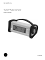
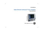
GE Healthcare
TruSat™ Pulse Oximeter
User’s Guide
GE Healthcare
TruSat™ Pulse Oximeter
User’s Guide
6050-0006-815
March 2005
Important
Rx Only (USA)
Attention! Consult the accompanying instructions, including all safety
precautions, before using this device.
Responsibility of the manufacturer
The safety, reliability, and performance of this device can be assured by the
manufacturer only under the following conditions:
• Assembly, extensions, readjustments, modifications, and repairs are carried out by
authorized personnel.
• The electrical installation complies with relevant standards and regulations.
• The device is used in accordance with this manual and is serviced and maintained in
accordance with the TruSat Technical Reference Manual.
Service and repair
Service and repair procedures must be performed by authorized service personnel.
Repair this device or its parts only in accordance with instructions provided by the
manufacturer. To order replacement parts or for assistance, contact an authorized
service office. When shipping the monitor for repair, clean the monitor, allow it to dry
completely, and pack it for shipment in the original shipping container, if possible.
Trademarks
Datex®, Ohmeda®, TruSat™ and other trademarks (ComWheel™, OxyTip®, PIr®,
TruSignal™, TruTrak®) are the property of GE Healthcare Finland Oy. All other product
and company names are the property of their respective owners.
0537
GE Healthcare Finland Oy
Helsinki, Finland
+358 10 394 11
www.gehealthcare.com
© 2005 General Electric Company. All rights reserved.
Contents
1. Overview
Monitor description...................................................................................................1–1
Trend Download option.......................................................................................................................1–1
Intended use .............................................................................................................................................1–1
TruSat pulse oximetry .............................................................................................1–2
TruSignal Enhanced SpO2 ..................................................................................................................1–2
PIr pulsatile value ...................................................................................................................................1–2
Measurement characteristics ..........................................................................................................1–2
Interfering substances................................................................................................................1–3
Calibration ........................................................................................................................................1–3
Safety precautions ....................................................................................................1–4
Warnings.....................................................................................................................................................1–4
Cautions ......................................................................................................................................................1–4
Electromagnetic compatibility (EMC)............................................................................................1–4
Disposal.......................................................................................................................................................1–4
2. Features and Use
Monitor features.........................................................................................................2–1
Connectors.................................................................................................................................................2–2
Information label and symbols .......................................................................................................2–2
Buttons and indicators ........................................................................................................................2–3
Power button and power LED.................................................................................................2–3
Alarm Silence button and indicator .....................................................................................2–3
Alarm LED..........................................................................................................................................2–3
Battery indicator............................................................................................................................2–4
On-screen controls ................................................................................................................................2–4
Using the monitor ......................................................................................................2–5
Monitor checkout....................................................................................................................................2–5
Choosing the sensor .............................................................................................................................2–6
Connecting the sensor.........................................................................................................................2–6
Monitoring the patient .........................................................................................................................2–7
Plethysmographic pulse bar (pleth bar).............................................................................2–7
Changing monitor settings ...................................................................................2–8
Using the ComWheel ............................................................................................................................2–8
Setting alarm limits................................................................................................................................2–8
Adjusting pulse beep and alarm volume....................................................................................2–9
Switching the backlight ON/OFF.....................................................................................................2–9
Locking/unlocking monitor settings..............................................................................................2–9
Displaying the perfusion index (PIr)............................................................................................ 2–10
Changing the line power filter....................................................................................................... 2–10
i
Contents
3. Alarms, Troubleshooting, & Maintenance
Alarms ..............................................................................................................................3–1
Alarm priorities.........................................................................................................................................3–1
Alarm activation ......................................................................................................................................3–1
Alarm signals.............................................................................................................................................3–2
Signals for multiple alarms .......................................................................................................3–2
Signals for silenced alarms.......................................................................................................3–2
Troubleshooting..........................................................................................................3–3
Maintenance .................................................................................................................3–5
Battery..........................................................................................................................................................3–5
Cleaning.......................................................................................................................................................3–5
Monitor................................................................................................................................................3–5
Sensors ...............................................................................................................................................3–5
Supplies and accessories....................................................................................................................3–6
Sensors ...............................................................................................................................................3–6
TruSat pulse oximeters ...............................................................................................................3–6
Miscellaneous..................................................................................................................................3–6
Trend Download option..............................................................................................................3–7
TruSat manuals ..............................................................................................................................3–7
4. Compliance and Specifications
Compliance....................................................................................................................4–1
Specifications ...............................................................................................................4–2
Measurement............................................................................................................................................4–2
General................................................................................................................................................4–2
SpO2 .....................................................................................................................................................4–2
Pulse rate...........................................................................................................................................4–2
PIr pulsatile value...........................................................................................................................4–2
Monitor .........................................................................................................................................................4–3
General................................................................................................................................................4–3
Display ................................................................................................................................................4–3
Alarms .................................................................................................................................................4–3
Audio ....................................................................................................................................................4–3
External power................................................................................................................................4–4
Internal battery power................................................................................................................4–4
Trend Download option..............................................................................................................4–4
Environmental conditions..........................................................................................................4–4
Dimensions and weight..............................................................................................................4–4
ii
Contents
A. Trend Download Option
Trend data collection .............................................................................................. A–1
Patient identification number...........................................................................................................A–1
Alarm annunciation capability .......................................................................... A–2
Setting the clock ........................................................................................................ A–2
Printing to the portable printer ......................................................................... A–3
Connecting the printer.........................................................................................................................A–3
Printing summary statistics for one or more patients.........................................................A–4
Sample printout: Summary statistics ................................................................................A–4
Printing real-time data.........................................................................................................................A–5
Sample printout: Real-time data..........................................................................................A–5
Trend Download PC software ............................................................................. A–6
PC requirements......................................................................................................................................A–6
Software installation.............................................................................................................................A–6
Setup.............................................................................................................................................................A–7
Starting the Trend Download program .......................................................................................A–7
Trend Download program options .......................................................................................A–7
B. Warranty
Warranty ........................................................................................................................B-1
iii
1. OVERVIEW
This chapter contains:
• A preview of the pulse oximetry features and measurement.
• General safety precautions to consider when using the monitor.
• A brief description of the monitor.
Monitor description
The TruSat™ pulse oximeter is a durable, reliable, and portable monitor. It features
TruSignal™ Enhanced SpO2 and PIr®, a relative perfusion index. The monitor is powered
by an internal battery, which is charged through an external power supply.
Important: When using the monitor for the first time or after removing it from
extended storage, charge the battery for three hours BEFORE you power ON.
The monitor contains an easy-to-read display with a backlight for low-light conditions.
Information that appears on the display includes the following:
• SpO2, pulse rate, and PIr measurements.
• All alarm limit settings.
• Indicators for plethysmographic pulse, battery capacity, and silenced alarms.
The monitor also contains on-screen controls for changing monitor settings, such as
alarm limits, volume, and the backlight. A lock function, when activated, protects against
unintended changes to settings.
The alarm system generates audible and visual signals that vary according to the
priority of the alarm.
Trend Download option
The Trend Download option allows you to set the monitor clock, print, and download
trends to a computer. Monitors can be factory-configured with this option. An upgrade
kit is also available.
NOTE: If your monitor is configured with the Trend Download option, be sure to set the
monitor clock before monitoring patients.
Intended use
The TruSat pulse oximeter is indicated for spot-checking and continuous monitoring of
functional oxygen saturation and pulse rate, including monitoring during conditions of
clinical patient motion1 or low perfusion. This device is intended for use with adult,
pediatric, and neonatal patients in both hospital and non-hospital environments.
Important: Only OxyTip®+ sensors can be used with this monitor.
1
Anesthesia & Analgesia. 2002;94,1S, S54-S60
1–1
TruSat User’s Guide
TruSat pulse oximetry
TruSignal Enhanced SpO2
TruSignal Enhanced SpO2 offers improved performance, especially during challenging
conditions of clinical motion and low perfusion. With ultra-low-noise technology,
TruSignal selects the appropriate clinically-developed algorithm to compensate for
weak or motion-induced signals and generate reliable saturation readings.
PIr pulsatile value
The perfusion index measurement—the PIr pulsatile value—is a quick and easy-to-use
clinical tool that provides a dynamic numeric reflection of perfusion at the sensor site.
PIr is a relative value that varies from patient to patient.
The PIr pulsatile value indicates the strength of the pulse signal at the sensor site—the
higher the PIr value, the stronger the pulse signal. A strong pulse signal increases the
validity of SpO2 and pulse rate data. Clinicians can use the PIr value to compare the
strength of the pulse signal at different sites on a patient in order to locate the best site
for the sensor—the site with the strongest pulse signal.
Measurement characteristics
The pulse oximetry measurement uses a two-wavelength pulsatile system—red and
infrared light—to distinguish between oxyhemoglobin (O2Hb) and reduced hemoglobin
(HHb). The light is emitted from the oximeter sensor, which contains the light source and
a photodetector.
• The light source consists of red and infrared light-emitting diodes (LEDs).
• The photodetector is an electronic device that produces an electrical current
proportional to incident light intensity.
The two light wavelengths generated by the LEDs are transmitted through the tissue at
the sensor site and are modulated by arterial blood pulsation. Since other fluids and
tissues present generally don’t pulsate, they don’t modulate the light. The pulsatile
portion of the incoming signal is used to detect and isolate the attenuation of light
energy due to arterial blood flow.
Variable absorption
(due to arterial pulse)
Arterial blood absorption
Venous blood absorption
Absorption
Other tissue absorption
Time
Figure 1-1. Comparative light absorption
1–2
Overview
The photodetector in the sensor converts the light intensity information into an
electronic signal. Since O2Hb and HHb absorb different amounts of the light that is
emitted from the oximeter sensor, different amounts of light reach the photodetector at
the selected wavelengths. The electronic signal varies according to which light source is
“on” (red or infrared) and the oxygenation of the arterial hemoglobin. This information is
used to calculate the relative percentage of O2Hb and HHb. The monitor processes the
electronic signal it receives from the photodetector. The SpO2 and pulse rate
measurements are continuously calculated as a 12-second “moving” average.
Interfering substances
Increased patient carboxyhemoglobin may falsely increase SpO2 readings in all brands
of pulse oximeters. Therefore, saturation readings may be higher for smokers, victims of
smoke inhalation, and patients with carbon monoxide (CO) intoxication. The level of
increase is approximately equal to the amount of carboxyhemoglobin present.
Methemoglobin from certain therapies, dyes that change arterial pigmentation, and
substances at the sensor site that contain dyes ( fingernail polish, for example) may also
cause erroneous readings.
Calibration
The TruSat pulse oximeter uses the functional calibration method. Functional saturation
is represented mathematically as the percentage of hemoglobin capable of carrying
oxygen that is carrying oxygen.
Functional SpO2 =
O2Hb
O2Hb
x 100 = O Hb + HHb
HbTOTAL – COHb – MetHb
2
(
)
(
) x 100
The calculation of SpO2 assumes 1.6% carboxyhemoglobin (COHb), 0.4%
methemoglobin (MetHb), and no interfering dyes. These values are based on the DatexOhmeda Pulse Oximeter Empirical Calibration Study. Appreciable variation from these
values will influence SpO2 accuracy.
NOTE: A hospital-grade CO-oximeter, which requires a sample of arterial blood and
typically uses four or more wavelengths of light, calculates carboxyhemoglobin (COHb)
and methemoglobin (MetHb) as well as O2Hb and HHb. CO-oximeter readings and pulse
oximeter readings will differ when COHb or MetHb is present.
1–3
TruSat User’s Guide
Safety precautions
Precautions associated with following safe practices while using the monitor appear
throughout this manual. General precautions are listed below. Carefully read all
precautions in this manual before using the monitor.
NOTE: For complete information about the safe and appropriate use of a sensor,
consult the instructions for that sensor.
Warnings
WARNINGS indicate potentially harmful situations that may cause injury to
a patient or operator.
• It is possible for any device to malfunction. Always verify unusual data by
performing a formal patient assessment.
• Do not use the monitor in the presence of any flammable anesthetic mixture.
• Use only hospital-grade, grounded power outlets.
• Use only sensors and cables specified for use with this monitor. Failure to do so may
cause interference with the measurement or result in increased emissions,
decreased immunity, or damage to the equipment or system.
• This monitor does not measure respiration and should never be used as a substitute
for an apnea monitor.
• This monitor is not intended for use in a magnetic resonance imaging (MRI)
environment.
Cautions
CAUTIONS indicate conditions that may lead to equipment damage or
malfunction.
• Do not store or use the monitor outside the temperature and humidity ranges stated
in the Specifications section of this manual.
Electromagnetic compatibility (EMC)
Electromagnetic interference, including interference from portable and mobile radio
frequency (RF) communications equipment, can affect this monitor.
When using this monitor, take precautions to ensure electromagnetic compatibility. For
more information, refer to the Technical Reference Manual.
Disposal
Recycle or dispose of this medical device, its components, and its packing materials in
accordance with local environmental and waste disposal regulations.
1–4
2. FEATURES AND USE
This chapter contains:
• Descriptions of the monitor’s features and controls.
• Instructions for using the monitor.
• Instructions for changing monitor settings.
Monitor features
NOTE: The monitor is shown without the handle.
Figure 2-1. Monitor features
1
Oxygen saturation (SpO2) measurement value
2
SpO2 high and low alarm limit settings, adjustable
3
Pulse rate measurement value
4
Pulse rate high and low alarm limit settings, adjustable
5
Plethysmographic pulse bar (pleth bar)
6
Alarm LED
7
Alarm Silence button
8
ComWheel navigation and selection knob for changing monitor settings
9
Display area for on-screen control symbols
10 Battery indicator
11 Power button and external power LED
2–1
TruSat User’s Guide
Connectors
WARNING: When you connect equipment to the monitor, you are configuring
a medical system and are responsible for ensuring that the system complies
with IEC 60601–1–1 and with local requirements. Connect only external
devices specified for use with this monitor.
WARNING: Use only sensors and cables specified for use with this monitor.
Failure to do so may cause interference with the measurement or result in
increased emissions, decreased immunity, or damage to the equipment or
system.
Sensor connector
Connect an OxyTip+
sensor or cable only.
Trend Download connector (RS-232)
Connect the TruSat printer or PC cable. See
Trend Download option later in this manual.
Power connector
Plug the power supply cable into this connector. Then, plug the
power cord into the power supply and into the AC power outlet.
Figure 2-2. Monitor connectors
Information label and symbols
A label on the underside of the monitor contains the model number, serial number, date
of manufacture, and other information about the monitor. The following symbols also
appear on this label and/or on the packaging for the monitor:
Sensor connector; defibrillation-proof
type BF applied part
DC current
RS-232 connector (Trend Download
option)
Manufacturer
Power supply connector; external
power in
Other symbols on the monitor or the screen are described in the appropriate sections of
this manual.
2–2
Features and Use
Buttons and indicators
Power button and power LED
Press the power button to power ON the monitor.
Press the button again to power OFF.
A green LED beside the power button is ON only while the monitor is connected to
external power. It does not indicate whether the monitor is powered ON or OFF.
NOTE: When you power OFF, all alarm limits and other monitor settings are saved.
When you power ON, all settings are restored with one exception: an SpO2 low alarm
limit setting below 85% is reset to 85%.
Alarm Silence button and indicator
WARNING: When alarms are silenced, observe the patient frequently.
A tone sounds each time you press the Alarm Silence button. The alarm LED is lit yellow
while alarms are silenced.
Press the Alarm Silence button once to silence all alarms for two
minutes.
Press it three times (rapidly) to silence all alarms indefinitely.
The alarm silence indicator is displayed at the upper right of the
screen while alarms are silenced. When alarms are silenced
indefinitely, it flashes ON/OFF.
To cancel the alarm silence, press the Alarm Silence button once again.
Alarm LED
The alarm LED beside the Alarm Silence button indicates the presence of an alarm and
the alarm priority:
LED Status
Priority
Meaning
Red ON or
Red flashing ON/OFF
High
Serious situation requiring an immediate
response.
Yellow flashing ON/OFF
Medium
Situation requiring a prompt response.
NOTE: The alarm LED is lit yellow while alarms are silenced.
For details about the TruSat alarm system, including all visual and audible alarm
indicators, see Alarms in chapter 3.
2–3
TruSat User’s Guide
Battery indicator
The battery indicator is displayed at all times, including when the monitor is powered
OFF and/or disconnected from AC power.
If external power is disconnected or lost during monitoring, the monitor switches to
battery power automatically.
Indicates the battery is fully charged. The number of shaded
segments decreases as the charge decreases.
NOTE: The number of shaded segments may temporarily decrease
when the monitor is connected to AC power and starts to recharge
the battery.
Indicates a low battery alarm condition; flashes ON/OFF. Monitor
can be powered by the battery only 10 to 60 minutes longer.
Connect the monitor to AC power to continue monitoring.
Important: When the battery is completely depleted, monitoring stops. A continuous
alarm tone sounds and the monitor powers OFF automatically. Connect the monitor to
external power immediately.
On-screen controls
You use the ComWheel to change alarm limit settings. You also use it to access the onscreen controls represented by the symbols described below.
Pulse beep volume
Alarm volume
Backlight, ON/OFF
PIr pulsatile value display, ON/OFF
Start/stop printing to a connected printer. For details, see Trend
Download option later in this manual.
Instructions for using the ComWheel to change and lock monitor settings are located
later in this chapter.
2–4
Features and Use
Using the monitor
Monitor checkout
Always check the operation of the monitor before using it to monitor a patient.
WARNING: Do not use the monitor if the startup tones do not sound, the
validity of data is questionable, or if the monitor fails to function as
described. Refer to the appropriate sections of this manual to identify and
correct the malfunction.
1.
Plug the power supply cable into the power connector on the monitor. Then, connect
the power supply to the power outlet.
Important: When using the monitor for the first time or after removing it from
extended storage, charge the battery for three hours BEFORE you power ON.
2.
Press the power button to power ON. Verify the following during startup:
• The power-on tones sound.
• All display elements, including on-screen symbols, illuminate briefly.
• The alarm LED is lit red, then yellow.
• The backlight is ON until dashes are displayed for the SpO2 and pulse rate. The
backlight remains ON if it is set to ON.
• (Trend Download option only) A patient number (P01, P02, etc.) is displayed.
3.
Power OFF and check the line power filter setting shown in the high pulse rate alarm
area: 50 (Hz) or 60 (Hz). If the setting matches your local line power frequency, go to
the next step. If it is different, go to Changing the line power filter later in this chapter.
4.
Choose a sensor designed for use on a finger, place it on your finger, and connect it
to the monitor. Power ON the monitor.
NOTE: All pleth bar segments pulsate until the measured values are displayed.
5.
When the SpO2 and pulse rate values are displayed, verify that the lowest pleth bar
segment remains visible while one or more of the other segments pulsate.
6.
Remove the sensor from your finger. Verify that the alarm LED flashes red, an alarm
tone sounds, and dashes replace the SpO2 and pulse rate values.
7.
Place the sensor on your finger again. After the SpO2 and pulse rate values are
displayed, unplug the sensor from the monitor. Verify that the alarm LED flashes red,
an alarm tone sounds, and dashes replace the values.
8.
Check the battery indicator. If the battery is low, recharge the battery before using
the monitor.
Important: If the startup tones do not sound or if the monitor fails to function as
described, DO NOT use the monitor until the malfunction has been corrected. Refer to
Troubleshooting later in this manual.
2–5
TruSat User’s Guide
Choosing the sensor
WARNING: Discard a damaged sensor or cable immediately. Never repair a
damaged sensor or cable; never use a sensor or cable repaired by others.
Choose a sensor that is appropriate for the patient and the situation. Use clean, dry, and
undamaged sensors and cables.
Important: Only OxyTip®+ sensors can be used with this monitor.
Reusable Sensors
Finger sensor. Widely-used. Quick application is
possible; may be used on toe.
Ear sensor. Similar in appearance to finger sensor,
but smaller.
Wrap sensor. Flexible sensor that is positioned
inside a soft wrap or tape and wraps around the
site (usually fingers, toes, or the fleshy part of a
hand or foot). Useful for small children.
Adhesive Sensors
Adhesive sensor that wraps around a finger or toe.
Used to minimize the effects of motion at the
sensor site.
Adhesive sensor with integrated cable. The sensor
is positioned inside tape that is wrapped around the
site to secure the sensor. Used on fingers, toes, and
the fleshy part of a hand or foot.
Connecting the sensor
To ensure the correct application and use of a sensor, refer to the instructions that were
provided with the sensor.
WARNING: To prevent erroneous readings, do not use a blood pressure cuff
or arterial blood pressure measurement device on the same limb as the
sensor.
2–6
1.
Apply the sensor to a clean, well-perfused site that is appropriate for the type of
sensor and for the patient. Use an adhesive sensor if the patient is exhibiting
significant motion that may interfere with the measurement.
2.
To minimize movement of the sensor, tape the sensor cable to the limb. Use a clip to
attach an ear sensor cable to bed clothes.
3.
Plug the sensor cable into the SpO2 connector on the monitor.
Features and Use
Monitoring the patient
If your monitor is configured with the Trend Download option, be sure to set the clock
before you begin monitoring. For instructions, see Trend Download option later in this
manual.
WARNING: Conditions that may cause inaccurate readings and impact
alarms include interfering substances, excessive ambient light, electrical
interference, excessive motion, low perfusion, low signal strength, incorrect
sensor placement, poor sensor fit, and movement of the sensor on the
patient.
WARNING: Patient conditions (such as reddening, blistering, skin
discoloration, ischemic skin necrosis, and skin erosion) may warrant
changing the sensor site frequently or using a different style of sensor.
WARNING: The power supply may reach a temperature that can cause
patient discomfort. Position the power supply so that it will not come into
contact with the patient.
Each time you monitor a patient:
• Verify that the signal strength is adequate and that the displayed values agree with
your clinical evaluation of the patient.
• Routinely check skin integrity and circulatory status at the sensor site.
• Adjust alarm limits according to the clinical condition of the patient.
Plethysmographic pulse bar (pleth bar)
The pleth bar—a column of up to ten pulsating segments—represents the
plethysmographic waveform. The pleth bar is displayed when a sensor is
correctly applied to the patient and connected to the monitor.
During monitoring, the lowest segment is always displayed; the other segments pulsate
(flash ON/OFF) in proportion to the pulse volume.
• The rate at which the segments pulsate represents the pulse rate.
• The highest pulsating segment indicates the strength of the pulse—the number of
pulsating segments increases as pulse strength increases.
The number of pulsating segments also indicates perfusion at the sensor site. For
example, a peak of ten segments indicates relatively high perfusion.
2–7
TruSat User’s Guide
Changing monitor settings
Using the ComWheel
You use the ComWheel to change monitor settings.
Press the ComWheel to display the pointer (
or
).
The backlight temporarily switches ON (if OFF). The on-screen control
symbols are displayed for several seconds.
Turn the ComWheel to move the pointer.
As you turn the ComWheel, the pointer appears beside each alarm limit
value or above each on-screen control symbol.
Press the ComWheel. New settings are effective immediately.
NOTE: When you press the ComWheel to change an alarm limit or
volume setting, the pointer flashes. Turn the ComWheel to display the
desired alarm limit or volume. The new setting is effective immediately,
however, if you want to continue changing settings, press the
ComWheel. Then turn the ComWheel to move the pointer to the next
setting.
Setting alarm limits
WARNING: To avoid rendering the alarm system useless, always set
reasonable alarm limits based on the clinical condition of the patient.
Alarm limit settings are saved and remain in effect each time you power ON the monitor
with one exception: a low SpO2 setting below 85% will be reset to 85%. The current high
and low alarm limit settings for SpO2 and pulse rate are displayed beside the SpO2 and
pulse rate values.
NOTE: Audible and visual alarm signals are not generated for any alarm limit that is set
to OFF.
1.
Press the ComWheel to display the pointer. Turn the ComWheel to move the pointer
to the limit you want to change (high SpO2, low SpO2, high pulse rate, or low pulse
rate).
2.
Press the ComWheel and, when the pointer flashes, turn the ComWheel until the
desired alarm limit or OFF (– – –) is displayed.
NOTE: Press the ComWheel to select the new setting if you plan to change more
monitor settings.
2–8
Features and Use
Adjusting pulse beep and alarm volume
1.
Use the ComWheel to move the pointer to the pulse beep volume symbol or the
alarm volume symbol.
The number of shaded bars indicates the current volume level.
Pulse beep volume
0, 1, 2, 3, or 4 shaded bars (0 = OFF)
Alarm volume
1, 2, 3, or 4 shaded bars (1 = low)
2.
Press the ComWheel and, when the pointer flashes, turn the ComWheel to change
the volume.
NOTE: Press the ComWheel to select the new setting if you plan to change more
monitor settings.
Switching the backlight ON/OFF
When the monitor is powered ON, the backlight setting is the same as when the monitor
was last powered OFF.
To change the backlight setting, use the ComWheel to move the pointer to
the backlight symbol, then press the ComWheel. When you switch the
backlight ON, the backlight symbol remains visible for several seconds.
Locking/unlocking monitor settings
You can lock the monitor to protect against unwanted changes to settings. You can set,
then lock alarm limit settings, volume settings, and the backlight. You can also silence
alarms indefinitely with the Alarm Silence button, then lock the monitor with the alarms
silenced indefinitely.
Important: When you silence alarms indefinitely and lock the monitor, only visual
alarm signals are activated when alarms occur. Audible alarm signals are silenced.
To lock or unlock monitor settings, press the ComWheel five times, holding it in for five
seconds on the fifth press. A tone sounds each time you lock or unlock the monitor.
The lock indicator is displayed at the lower right of the screen while monitor
settings are locked.
If alarms are silenced indefinitely before the monitor is locked, only the power button is
functional. The ComWheel can be used only to unlock the monitor as described above.
2–9
TruSat User’s Guide
Displaying the perfusion index (PIr)
To display the PIr value, use the ComWheel to select the PIr symbol. The
pointer continues to flash as long as the PIr value is displayed. To cancel the
display, press the ComWheel.
Figure 2-3. Perfusion index (PIr) display
NOTE: If a pulse rate alarm occurs while the PIr value is displayed, the alarm LED flashes
yellow. An alarm tone sounds unless alarms are silenced. Press the ComWheel to view
the pulse rate display.
Changing the line power filter
For the best low perfusion performance, set the line power filter to match the line power
frequency of your local AC power source. The software line power filter will then
eliminate potential interference when you use AC power or when you use battery power
near an AC power source.
When you power OFF the monitor, the line power filter setting (50 or 60) is displayed in
the high pulse rate alarm area.
1.
To change the line power filter setting, power ON the monitor. Press the ComWheel
seven times, holding it in on the seventh press until the new setting is displayed: 50
H(z) or 60 H(z).
Figure 2-4. Changing the line power filter
2.
2–10
To check the setting, power OFF and verify that the new setting is displayed in the
high pulse rate alarm area.
3. ALARMS, TROUBLESHOOTING, & MAINTENANCE
This chapter contains:
• Information about the alarm system.
• A chart for troubleshooting situations that may occur while using the monitor.
• Maintenance information, including a list of supplies and accessories that are
approved for use with the monitor.
Alarms
Alarms are visual or audible signals that alert you to a physiological or technical alarm
condition.
• Physiological alarm conditions occur when an SpO2 or pulse rate measurement
matches or exceeds the alarm limit setting.
• Technical alarm conditions occur when the monitor detects an equipment-related
condition, such as a depleted battery, a faulty sensor, or an internal malfunction.
Alarm priorities
Alarms are prioritized according to the severity and urgency of the alarm condition. This
allows you to identify and respond immediately to the highest priority alarms. The alarm
priorities are high and medium.
• High priority alarms indicate a serious situation that requires an immediate response.
• Medium priority alarms indicate a situation requiring a prompt response.
Alarm activation
Visual alarm signals are activated when a measured value matches or exceeds its alarm
limit. The audible alarm signal is activated within ten seconds. However, the alarm tone
sounds immediately when the SpO2 value is more than two digits beyond its alarm limit
setting, or when the pulse rate value is more than five digits beyond its alarm limit
setting.
3–1
TruSat User’s Guide
Alarm signals
An alarm condition generates audible and visual signals according to the alarm priority.
When an alarm condition occurs, the backlight switches ON (if OFF) until the alarm
condition ends. All audible and visual alarm signals are cleared when the alarm condition
ends.
Priority
Alarm LED
Audible signal
Alarm description
High
Red ON or
flashing ON/OFF
Continuous tone or five
beeps (beep-beep-beep,
beep-beep with falling
tone) twice every
10 seconds.
The sensor is off, not attached, or the
monitor is unable to measure the signal.
Dashes are displayed.
SpO2 value flashes; measurement
matched or exceeded an alarm limit.
System error or sensor error. Message
and error number are displayed.
The battery is completely depleted.
Medium
Yellow flashing
ON/OFF
Three beeps (beep-beepbeep with falling tone)
every 20 seconds.
Pulse rate value flashes; measurement
matched or exceeded an alarm limit.
Battery is low. Battery indicator flashes
ON/OFF.
Signals for multiple alarms
During multiple alarm conditions, the visual and audible alarm signals always indicate
the highest priority alarm. For example, if a medium priority alarm is present when a
high priority alarm occurs, the high priority alarm signals replace the medium priority
alarm signals.
Signals for silenced alarms
When you press the Alarm Silence button to silence one or more alarms, the alarm LED
indicates the highest priority alarm condition. All other visual alarm indicators (flashing
value, dashed display, etc.) are displayed until the alarm condition ends.
If no alarms are present when you press the Alarm Silence button, the alarm LED is lit
yellow to indicate upcoming alarms will be silenced. If an alarm condition occurs while
alarms are silenced, the alarm LED indicates the priority of the alarm. All other visual
alarm indictors are displayed until the alarm condition ends.
3–2
Alarms, Troubleshooting, & Maintenance
Troubleshooting
Always check the condition of the patient first. If a problem persists, contact authorized
service personnel.
Situation
Flashes ON/OFF.
Dashes are displayed for
measurement.
and/or
Cause
Recommendation
Low battery. Monitor can be
powered by battery only 10 to 60
minutes longer.
Connect the monitor to external power to
recharge the battery.
NOTE: Pressing the Alarm Silence
button once will cancel the alarm.
Poor signal quality due to a
disconnected sensor, poor sensor
placement, low perfusion, or
interference, for example.
The pulse strength is considered low
when only the lower four pleth bar
segments pulsate.
NOTE: When this condition is
caused by disconnection of the
sensor from the monitor or patient,
pressing the Alarm Silence button
once will cancel the alarm.
Four or fewer pleth bar
segments pulsate.
NOTE: When the battery is completely
depleted, all display and measurement
functions are switched OFF and a
continuous alarm tone sounds.
Connect the sensor to the monitor.
Apply the sensor as directed in the
instructions for the sensor.
• Make sure the sensor detector is
completely covered by the patient’s skin
and is directly opposite the light source.
• Remove debris from the sensor detector
and light source.
• If the site is thick, select a site where
there is less distance between the light
source and the detector.
•
(Ear) Gently massage the sensor site to
increase perfusion.
•
(Finger or Toe) Remove polish and
artificial fingernails; clip long nails.
Remove sources of interference, such as an
electrosurgical device or excessive ambient
light.
Change the sensor site or use a different
style of sensor.
Dashes are displayed for
measurement.
Signal interference due to incorrect
line power filter setting, poor
grounding at the AC power source,
or adjacent sensors (two or more
SpO2 sensors on the same hand or
foot, for example).
• Change the line power filter setting. See
Changing the line power filter in
chapter 2.
• Use battery power or use a grounded
AC power source for the monitor,
printer, and/or PC.
• Apply only one sensor to the hand, foot,
or other site.
Continuous, severe motion.
Calm the patient, change the sensor site, or
use a different style of sensor.
Faulty or incompatible sensor.
Replace the sensor. Use only OxyTip+
sensors. If the message reappears, note the
error number and contact authorized
service personnel.
NOTE: An error number appears in
the high SpO2 alarm limit area.
Internal malfunction.
NOTE: An error number appears in
the high SpO2 alarm limit area.
Power OFF, then ON again. If the message
reappears, note the error number and
contact authorized service personnel.
3–3
TruSat User’s Guide
Situation
Cause
Recommendation
Pulse rate and/or pleth bar
vary significantly from the
palpated pulse rate.
Incorrect sensor placement, motion
at the sensor site, low signal
strength, or electrical interference. A
cough or other hemodynamic
pressure disturbance can also
disrupt the signal.
• Apply the sensor as directed in the
instructions for the sensor.
Displayed values and/or
pleth bar do not correlate
to the physiological
condition of the patient.
Electromagnetic interference.
Remove the source of electromagnetic
interference. Use the monitor within its
intended electromagnetic environment.
Tones did not sound during
startup.
Alarm system failure or internal
malfunction.
Power OFF, then ON again. If the tones do
not sound, DO NOT use the monitor.
Contact authorized service personnel.
Display is blank.
Continuous tone may
sound.
Internal malfunction.
Power OFF, then ON again. If the problem
persists, contact authorized service
personnel.
Monitor will not power ON.
Battery is completely depleted or
has failed.
Connect the monitor to external power and
charge the battery for up to 30 minutes
before attempting to power ON.
• Restrict motion at the sensor site,
choose a site where motion is less likely,
or use an adhesive sensor.
• Remove sources of electrical
interference, such as electrosurgical and
electronic devices.
NOTE: After recharging a battery that was
completely depleted, it may be necessary
to cycle power ON/OFF several times.
If the problem persists, contact authorized
service personnel.
Power button or Alarm
Silence button is not
working.
Button is stuck due to debris (lint, for
example), button is damaged, or a
circuit board is faulty.
Contact authorized service personnel.
Power supply cable
disconnects easily from the
power jack.
Worn or damaged power jack
assembly.
Contact authorized service personnel.
3–4
Alarms, Troubleshooting, & Maintenance
Maintenance
Battery
To extend the life of the battery:
• Fully charge the battery once a month.
NOTE: After all four battery segments are shaded, wait at least 20 minutes before
you disconnect the monitor from the external power source so the monitor can
refresh the battery.
• Fully discharge the battery once every six months.
To discharge the battery, use battery power for monitoring a patient until only one
segment of the battery indicator is shaded. Then, connect the monitor to external power
and fully recharge the battery.
NOTE: The battery can be recharged only when the internal temperature of the monitor
is between 0 °C and 40 °C (32 °F and 104 °F).
Cleaning
Monitor
CAUTION: Do not autoclave, pressure sterilize, or gas sterilize the monitor. Do
not immerse the monitor in liquid or allow liquid to enter the interior.
CAUTION: Abrasive materials or harsh chemicals may damage the surface of
the monitor. Do not use petroleum-based solutions or solutions containing
acetone, freon, or harsh solvents.
1.
Power OFF the monitor.
2.
Disconnect all cables from the monitor: power supply, sensor, and any cable
connected to the RS-232 port.
3.
Wipe the display lens with a cotton swab moistened with one of the following
cleaning agents:
4.
Mild detergent solution
0.5% sodium hypochlorite (bleach)
70% isopropyl alcohol
Quarternary germicides (Virex®)
1.6% phenol (Sporicidin®)
3.4% glutaraldehyde (Cidex® Plus)
Wipe the case with a soft cloth dampened with a cleaning agent. Do not allow
excess liquid to enter through a connector.
Sensors
To clean a reusable sensor, refer to the instructions that are provided with the sensor.
NOTE: Disposable sensors are intended for single-patient use only. Discard them after
use.
3–5
TruSat User’s Guide
Supplies and accessories
All monitor configurations include a power supply and a power cord. Monitors
configured with the Trend Download option also include the Trend Download
software CD and the TruSat/PC RS-232 cable.
Service kits and replacement parts are also available. They are listed in the TruSat
Technical Reference Manual.
Sensors
Refer to the sensor chart that accompanies this manual for a list of the sensors
and sensor-related accessories approved for use with this monitor. Only OxyTip+
sensors can be used with this monitor.
TruSat pulse oximeters
TruSat, yellow ........................................................................................................6051-0000-190
TruSat, white ..........................................................................................................6051-0000-192
TruSat with Trend Download option, yellow..........................................6051-0000-191
TruSat with Trend Download option, white ............................................6051-0000-193
Miscellaneous
Pole mount..............................................................................................................6050-0007-197
Carrying case, nylon..........................................................................................6050-0006-585
Battery pack...........................................................................................................6050-0006-578
For installation by authorized service personnel only.
Power supply (AC to DC converter).............................................................6050-0006-579
Power supply (optional)
for use with 12 VDC vehicle cigarette lighter ...............................6021-0000-042
Power cords
Socket Type:
Commonly Used In:
Australia, China
6030-0000-001
Canada, Japan, Latin America, USA
0208-0943-300
Continental Europe
6030-0000-006
Italy
6030-0000-002
United Kingdom
6050-0002-259
NOTE: The National Electrical Manufacturers Association (NEMA) ratings for
power cords used in North America are: NEMA 5-15P (120 VAC) and NEMA 6-15P
(240 VAC).
3–6
Alarms, Troubleshooting, & Maintenance
Trend Download option
Trend Download option, upgrade kit......................................................... 6050-0007-164
For installation by authorized service personnel only.
Includes Trend Download software CD, TruSat/PC RS-232 cable,
circuit board with RS-232 connector, and installation hardware
Trend Download software CD....................................................................... 6050-0006-586
Cable, TruSat/PC RS-232 ................................................................................. 6050-0006-924
Cable, TruSat/serial printer............................................................................. 6050-0006-925
Printer assembly
US....................................................................................................................... 6050-0007-165
Europe ............................................................................................................. 6050-0007-167
Japan ............................................................................................................... 6050-0007-166
NOTE: Each printer assembly includes:
Serial printer and instructions
Cable, TruSat/serial printer
Printer paper, 1 roll
Printer battery pack
Printer power supply (US, Europe, or Japan)
Printer paper, 5 rolls........................................................................................... 6002-0000-200
Printer battery pack........................................................................................... 6002-0000-203
Printer power supply
US....................................................................................................................... 6002-0000-199
Europe ............................................................................................................. 6002-0000-201
Japan ............................................................................................................... 6002-0000-202
TruSat manuals
Technical Reference Manual, English......................................................... 6050-0006-813
User’s Guide
Czech................................................................................................................ 6050-0007-242
Danish.............................................................................................................. 6050-0006-817
Dutch................................................................................................................ 6050-0006-819
English ............................................................................................................. 6050-0006-815
Finnish ............................................................................................................. 6050-0006-821
French.............................................................................................................. 6050-0006-823
German........................................................................................................... 6050-0006-825
Hungarian...................................................................................................... 6050-0007-244
Italian ............................................................................................................... 6050-0006-827
Japanese........................................................................................................ 6050-0006-829
Norwegian..................................................................................................... 6050-0007-332
Polish................................................................................................................ 6050-0006-831
Portuguese.................................................................................................... 6050-0006-833
Russian............................................................................................................ 6050-0007-246
Spanish ........................................................................................................... 6050-0006-835
Swedish........................................................................................................... 6050-0006-837
3–7
4. COMPLIANCE AND SPECIFICATIONS
This chapter contains:
• Medical electrical equipment standards and compliance information for the monitor.
• Specifications.
Compliance
European Union Medical Device Directive 93/42/EEC: Class IIb
EN 60601-1 Medical electrical equipment – Part 1: General requirements for safety
(including Amendments 1 and 2)
• Type of protection against electric shock: Class I equipment/Internal electrical power
source
• Degree of protection against electric shock: Defibrillation-proof type BF applied part
• Degree of protection against ingress of water (EN 60529): IPX2
• Not suitable for use in the presence of flammable anesthetic mixtures
• Mode of operation: Continuous
EN 60601-1-2 (2nd Edition) Electromagnetic compatibility – Requirements and tests
CISPR 11/EN 55011 (Protection against emissions): Group I, Class B
IEC 60601-1-8 Alarm systems – General requirements, tests and guidance for alarm
systems in medical electrical equipment and systems
Medical electrical equipment classified in the US and Canada with respect to
electric shock, fire, and mechanical hazards only, in accordance with the
Canadian Standards Association CAN/CSA C22.2 No. 601.1 and Underwriters
Laboratories Inc. UL 2601–1.
4–1
TruSat User’s Guide
Specifications
Specifications are nominal and are subject to change without notice.
Measurement
General
Pulse oximetry sensors: OxyTip+ sensors only
Method: red and infrared light absorption
Red LED wavelength range: 650 to 670 nm
Infrared (IR) LED wavelength range: 930 to 950 nm
Average power: ≤ 1 mW
SpO2
Calibrated for functional oxygen saturation
Calibration range: 70 to 100%
Measurement and display range: 1 to 100%
Display resolution: 1%
First reading, full accuracy: ≤ 10 seconds
Accuracy, Arms (root mean square of paired values; previously represented by
± 1 standard deviation)
70 to 100% ± 2 digits (without motion)
70 to 100% ± 3 digits (during clinical motion) 2
70 to 100% ± 2 digits (during clinical low perfusion)
Below 70% unspecified
SpO2 measurement accuracy is based on deep hypoxia studies using OxyTip+ sensors
on volunteer subjects. Arterial blood samples were analyzed simultaneously on multiple
CO-oximeters.
NOTE: Accuracy may vary for some sensors; always check the instructions for the
sensor.
Pulse rate
Measurement and display range: 30 to 250 beats per minute (bpm)
Display resolution: 1 bpm
First reading, full accuracy: ≤ 15 seconds
Accuracy
30 to 250 bpm: ± 2 digits or ± 2%, whichever is greater, (without motion)
30 to 250 bpm: ± 5 digits (during motion)
30 to 250 bpm: ± 3 digits (during low perfusion)
PIr pulsatile value
Measurement and display range: 0.01 to 9.99
Display resolution: 0.01 PIr
2
Applicability: OxyTip+ Adult/Pediatric and AllFit sensors.
4–2
Compliance and Specifications
Monitor
General
Lock function: locks/unlocks alarm limits and other settings
Factory calibrated; power-on self-test with calibration check
Recovery time after exposure to defibrillation voltage: ≤ 30 seconds
Display
Liquid crystal display (LCD)
Backlight LED: ON or OFF
Plethysmographic pulse bar (pleth bar): ten-segment column; pulsates to indicate pulse
rate and signal strength
Display update time
SpO2, pulse rate, and PIr values: 1 second ± 0.25 second
Plethysmographic pulse bar: 20 Hz minimum (.05 second)
Alarms
Visual and audible indicators for physiological alarms (SpO2 and pulse rate limit alarms)
and technical alarms (sensor condition, battery condition, internal malfunction)
Visual alarm indicator, red/yellow LED
High priority alarm: red ON or red flashing ON/OFF
Medium priority alarm: yellow flashing ON/OFF
Visibility (operator positioned in front of monitor): 4 m (13 ft.) at 30° angle in any
direction
NOTE: When an SpO2 or pulse rate alarm limit is violated, the related measurement
flashes ON/OFF.
Audible alarm indicator: pattern varies according to alarm type and priority
Alarm Silence button: silences alarms for 2 minutes (press once; alarm silence indicator
is displayed) or indefinitely (press 3 times; indicator flashes ON/OFF)
NOTE: If an alarm condition is not present, the alarm LED is lit yellow to indicate
future alarms will be silenced.
Alarm
Range
Factory setting
High SpO2
51 to 100% or OFF (— —)
OFF
Low SpO2
50 to 99% or OFF (— —)
85
High pulse rate
30 to 235 bpm or OFF (— — —)
130
Low pulse rate
30 to 235 bpm or OFF (— — —)
40
Audio
Pulse rate beep: tone rises as oxygen saturation increases and falls as it decreases
Adjustable volume: 4-segment on-screen control
Pulse beep volume: 0 (OFF), 1, 2, 3, or 4 shaded segments
Alarm volume: 1 (low), 2, 3, or 4 shaded segments
Volume intensity at distance of 1 m (3.28 ft.): 45 dB minimum to 85 dB maximum
4–3
TruSat User’s Guide
External power
Power supply (AC to DC converter)
AC power input: 100–240 V, 0.5 A, 50–60 Hz
Power supply (DC to DC)
DC power input from vehicle cigaretter lighter: 12 V
Power supply output to monitor: 12 VDC, 1.25 A, 15 watt
Power indicator (green LED): ON while monitor is connected to AC power
Line power filter (monitor setting): 50 Hz or 60 Hz
Internal battery power
Type: Internal, rechargeable, nickel metal hydride (NiMH), 3 AH, 12 VDC, 150 mA
Self-discharge when stored at room temperature (typical for all NiMH batteries):
at least 30% of a full charge remains after 3 months of storage
Capacity, fully charged, operating at room temperature:
Without Trend Download option: 35 hours
With Trend Download option: 24 hours
NOTE: Continuous use of the backlight reduces the time approximately 50%.
Charging time (full capacity): 3.5 hours typical
Battery indicator: 4-segment symbol; shaded segments represent battery charge
(0 shaded = low or depleted; 4 shaded = fully charged)
Automatic power OFF to conserve battery: 20 minutes after monitoring stops
Trend Download option
Trend data storage: 48 hours with a data storage resolution of 1 data point every
4 seconds
RS-232 serial port: DIN 6 circular connector
19.2K baud, 8 data bits, 1 start bit, 1 stop bit
Handshaking (RTS, CTS), full duplex, no parity
Environmental conditions
NOTE: To maximize battery life, store the monitor at room temperature.
Operating
Transport and Storage
Temperature
10 to 40 ºC
(50 to 104 ºF)
–40 to 70 ºC
(–40 to 158 ºF)
Relative humidity,
noncondensing
20 to 95%
5 to 95%
Atmospheric pressure
1060 to 697 hPa
1060 to 188 hPa
Approximate elevation
–378 to 3048 m
(–1240 to 10,000 ft.)
–378 m to 12.2 km
(–1240 to 40,000 ft.)
Dimensions and weight
Width/Depth/Height including handle = 21.8 x 11.5 x 10.3 cm (8.5 x 4.5 x 4 inches)
Weight
1.25 kg (2.76 pounds)
1.47 kg (3.26 pounds) with Trend Download option
4–4
A. TREND DOWNLOAD OPTION
Monitors configured with the Trend Download option are equipped with an RS-232
port for connecting a portable printer or a computer. The Trend Download option
expands the capabilities of the monitor to include the following:
• Collecting and storing patient monitoring data, or trends.
• Alarm annunciation.
• Setting the monitor clock.
• Printing trends or real-time data to an attached printer.
• Downloading trends to an attached computer.
Trend data collection
Trends are collected continuously and stored indefinitely, unless battery power is
lost. The monitor stores the patient number, time, date, measurement values (SpO 2,
pulse rate, and PI r ), SpO 2 limit violations, sensor OFF status, and alarm audio status.
The monitor can store a total of 48 hours of trends for up to 99 patients, depending on
how long each patient is monitored. A data point is stored every 4 seconds.
Patient identification number
When you power ON the monitor, a patient number (P01, P02 … P99) is displayed for
one second. The patient number is stored with the trend data collected during
monitoring and appears on printouts and reports to identify the data for that
patient. The patient number increments by one each time you power OFF the
monitor, connect a new patient, and power ON. It also increments when you power
OFF, then ON while monitoring the same patient.
Important: Each time you begin monitoring a new patient, power the monitor OFF,
then ON. Otherwise, trends for more than one patient will be stored under a single
patient number.
When the patient number exceeds P99, the numbering restarts at P01 and trends
currently stored in memory for P01 are erased. When memory is full, approximately
25% (12 hours) of the oldest trends are erased to make memory available for new
data.
NOTE: Patient numbering also restarts at P01 when all trends are erased from
memory, using the Trend Download PC software.
A–1
TruSat User’s Guide
Alarm annunciation capability
The Trend Download option lets you connect the TruSat to your local “nurse call”
system for automatic transmission of signals when alarms occur. To enable this
feature, authorized service personnel must do the following:
• Customize a cable for connecting your system to the TruSat.
• Change the position of a switch on the Trend Download board.
Instructions are located in the TruSat Technical Reference Manual.
WARNING: Alarm annunciation is not functional while alarms are silenced
and should never be used as the main notification of an alarm condition. An
alarm condition can be determined only by evaluating the clinical condition
of the patient together with audible and visual alarm signals.
Setting the clock
The date and time are included on printouts and with data downloaded to a PC.
Clock settings are stored indefinitely unless battery power is lost.
Important: Set the clock before you begin monitoring to ensure that all patient
records contain the correct time and date.
NOTE: You can also use the Trend Download PC software to set the clock.
1.
Unplug the sensor from the monitor and power ON.
2.
Press the ComWheel three times, holding it in for five seconds on the third press.
Each clock option (year, month, etc.) is displayed sequentially in the pulse rate
field. The setting (3, 12, etc.) is displayed in the SpO2 field. The time is based on a
24-hour clock.
When you see …
A–2
You can choose …
When you see …
You can choose …
year (0–99)
hour (0–23)
month (1–12)
minute (0–59)
day (1–31)
exit
3.
Turn, then press the ComWheel to select a clock option. The selected option
flashes ON/OFF. Turn, then press the ComWheel to select the setting for that
option. Repeat to set each clock option.
4.
When you are finished, use the ComWheel to select exit.
Trend Download Option
Printing to the portable printer
The portable printer is optional. See Supplies and accessories for ordering
information. Refer to the instructions that came with the printer for details regarding
changing the paper, clearing paper jams, DIP switch settings, etc.
NOTE: If you are unable to print, check the printer DIP switch settings in the
instructions for the printer.
Connecting the printer
The TruSat/serial printer cable, a roll of paper, a battery pack, and a power supply for
the printer are included with the printer.
WARNING: When you connect equipment to the monitor, you are
configuring a medical system and are responsible for ensuring that the
system complies with IEC 60601–1–1 and with local requirements. Connect
only external devices specified for use with this monitor.
Paper cover
Paper cover window
Power switch
Power lamp
1.
Connect the TruSat/serial printer cable to the monitor and to the printer.
2.
Connect the printer power supply to the printer and to the AC power outlet.
3.
Power ON the printer.
Important: Make sure a sufficient amount of paper is installed in the printer before
you begin printing. After printing, photocopy the printout for your records.
Exposure to heat or light can destroy thermal paper printouts.
A–3
TruSat User’s Guide
Printing summary statistics for one or more patients
You can print a statistical summary of each record stored in the monitor. Trends for
the most recent patient are printed first.
1.
After monitoring one or more patients, unplug the sensor from the monitor.
NOTE: Press the Alarm Silence button to silence alarms.
2.
Connect the printer.
3.
To start printing, use the ComWheel to move the pointer to the print
symbol, then press the ComWheel. Repeat to stop printing.
The print symbol is displayed during printing.
Important: The monitor calculates the data before printing begins. When printing
a long record for a single patient, printing will be delayed approximately
1 minute for every 24 hours of data. The monitor may appear to be inactive,
however, printing will begin when the calculation is completed.
Sample printout: Summary statistics
Trends, most recent patient
General information:
• Patient number and lines for
adding information.
• Start time, start date, and duration,
based on monitor clock settings.
• Total time readings were valid.
• Total time readings were not
collected because, for example, the
sensor was off the patient.
Statistical summary:
• Lowest and average SpO2 readings
and their standard deviation.
• Percentage of time SpO2 readings
were within specific ranges.
• Maximum number of minutes SpO 2
was continuously below 90%.
• Maximum number of minutes SpO 2
was continuously at or below 85%.
NOTE: Printing continues until all trends stored in memory for previous patients are
printed or until printing is stopped.
A–4
Trend Download Option
Printing real-time data
Real-time printouts are intended for archival or record-keeping purposes only. The
patient record is also stored in trend memory.
1.
2.
Connect the printer and begin to monitor the patient.
To start printing, use the ComWheel to move the pointer to the print
symbol, then press the ComWheel. Repeat to stop printing.
The print symbol is displayed during printing.
Sample printout: Real-time data
Current patient data
General information:
• Patient number and lines for
adding information.
• Legend for symbols in the STATUS
column.
• The time and date printing started,
based on monitor clock settings.
Data at 4-second intervals:
• Lowest SpO2 reading and the
accompanying pulse rate (PR), PI r ,
and alarm status.
• Status of SpO 2 limit violations,
sensor error, and alarm silence. For
example, ?X means the sensor was
off the patient or disconnected (?)
AND alarms were silenced (X).
A–5
TruSat User’s Guide
Trend Download PC software
The Trend Download (TD) software lets you access data stored on the
monitor and download that data to a connected personal computer.
You can create detailed, easy-to-read reports containing trends for
individual patients.
The Trend Download option includes the following equipment for connecting a PC to
the TruSat and downloading trends:
• Compact disc (CD) containing the Trend Download PC software and instructions
(pdf).
• TruSat/PC RS-232 cable.
NOTE: The Trend Download PC program interface (menus, messages, etc.) is in
English.
PC requirements
• Microsoft® Windows® 2000 and XP
• Intel® Pentium® 90 MHz processor (minimum)
• 32 MB RAM and at least 4 MB available on the hard drive
• CD-ROM drive
Software installation
1.
Power ON the PC and insert the Trend Download CD into the CD drive.
A start-up screen is displayed. If the start-up screen is not displayed, select the
CD drive and open the CD. Then, double-click Setup.exe to display the screen.
2.
Follow the prompts to install the software:
C:\Program Files\Datex-Ohmeda\Trend Download
You may select a different location, if desired.
A–6
Trend Download Option
Setup
WARNING: When you connect equipment to the monitor, you are
configuring a medical system and are responsible for ensuring that the
system complies with IEC 60601–1–1 and with local requirements. Connect
only external devices specified for use with this monitor.
Connect the TruSat/PC RS-232 cable to the RS-232 port on the PC and to the Trend
Download RS-232 port on the side panel of the monitor.
Starting the Trend Download program
1.
If you plan to download trends or change monitor settings, power OFF the
monitor and unplug the sensor.
NOTE: You cannot download trends when a sensor is connected to the monitor.
2.
Connect the monitor to the computer and power ON the computer and monitor.
3.
To launch the program on the PC, select the Trend Download program or screen
icon.
4.
After using the Trend Download program to download data or change monitor
settings, power OFF the monitor.
Trend Download program options
When you launch the program, the main screen is displayed. It contains menus and
buttons with the functions noted below:
Menus
• File—open a downloaded data file, save the file, and exit the program.
• Help—access information about the program.
Buttons
• Download Trend Data—download data from the TruSat to the PC.
• Oximeter Settings—set the clock; clear all trend data from oximeter memory.
• Create Trend Download (TD) Report—view, adjust times, and generate a report.
• Trend Download (TD) Report Options—add your logo; enter information for the
report header (patient name; location name, address, and phone number).
Refer to the instructions located on the Trend Download CD for details.
A–7
B. WARRANTY
The TruSat pulse oximeter (the Product) is sold by GE Healthcare (the Company) only under
the warranties set forth in the following paragraphs. Such warranties are extended only
with respect to the purchase of the Product directly from the Company’s Authorized Dealers
as new merchandise and are extended to the first buyer thereof, other than for resale. The
Company warrants that the Product meets the published specifications at the time of
shipment from the factory.
Products not under warranty
The following items are not covered under this warranty: disposable items, accessories,
service kits, and replacement parts. These items may be covered under a separate warranty.
Consult the Company for details.
Duration
The Product is warranted against defects in materials and workmanship for a period of
three (3) years from the date of delivery to the user (in no event for a period of more than four
[4] years from the date of original delivery by the Company to an Authorized Dealer). The
internal battery is warranted against defects in materials and workmanship for a period of
one (1) year from the date of delivery to the user.
If any part of the Product proves defective under proper and normal use within the warranty
period, as the purchaser's exclusive remedy, the Company will repair or replace, at its sole
discretion, the Product or any defective part provided it is returned to an authorized Service
Center within 30 days of the failure.
Limitation
The Company may at any time discharge its warranty obligation by repairing and
returning the Product to original factory performance. This may be accomplished by
installing new or remanufactured assemblies or by other repairs deemed appropriate by the
Company. The choice of repair or replacement by the Company shall be the sole remedy of
the buyer or user.
This warranty is valid only when qualified personnel have performed installation and
service on the Product and when all recommended planned maintenance procedures have
been completed during the warranty period. Damage caused by the abuse or misuse of the
Product is not covered by this warranty. The Company shall not be liable for damage
resulting from the improper installation or the misuse of the Product.
Exclusion of warranties
Oral statements about the Product do not constitute warranties, shall not be relied on by
the buyer or user, and are not part of any warranty extended by the Company.
Except as set forth in this limited warranty, the Company makes no warranties, expressed or
implied, including the implied warranty of merchantability and the implied warranty of
fitness for a particular purpose. Except for the obligations under this limited warranty, the
Company shall not have any obligation or liability for any incidental or consequential
damages (including those from commercial loss) or other loss, damage, or injury resulting
directly or indirectly from the Product.
B–1