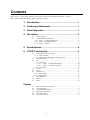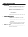
1
USER MANUAL NL120 Ethernet Module Issued: 8.4.14 Copyright © 2006-2014 Campbell Scientific, Inc. Printed under licence by Campbell Scientific Ltd. CSL 812 Guarantee This equipment is guaranteed against defects in materials and workmanship. This guarantee applies for twelve months from date of delivery. We will repair or replace products which prove to be defective during the guarantee period provided they are returned to us prepaid. The guarantee will not apply to: • Equipment which has been modified or altered in any way without the written permission of Campbell Scientific • Batteries • Any product which has been subjected to misuse, neglect, acts of God or damage in transit. Campbell Scientific will return guaranteed equipment by surface carrier prepaid. Campbell Scientific will not reimburse the claimant for costs incurred in removing and/or reinstalling equipment. This guarantee and the Company’s obligation thereunder is in lieu of all other guarantees, expressed or implied, including those of suitability and fitness for a particular purpose. Campbell Scientific is not liable for consequential damage. Please inform us before returning equipment and obtain a Repair Reference Number whether the repair is under guarantee or not. Please state the faults as clearly as possible, and if the product is out of the guarantee period it should be accompanied by a purchase order. Quotations for repairs can be given on request. It is the policy of Campbell Scientific to protect the health of its employees and provide a safe working environment, in support of this policy a “Declaration of Hazardous Material and Decontamination” form will be issued for completion. When returning equipment, the Repair Reference Number must be clearly marked on the outside of the package. Complete the “Declaration of Hazardous Material and Decontamination” form and ensure a completed copy is returned with your goods. Please note your Repair may not be processed if you do not include a copy of this form and Campbell Scientific Ltd reserves the right to return goods at the customers’ expense. Note that goods sent air freight are subject to Customs clearance fees which Campbell Scientific will charge to customers. In many cases, these charges are greater than the cost of the repair. Campbell Scientific Ltd, Campbell Park, 80 Hathern Road, Shepshed, Loughborough, LE12 9GX, UK Tel: +44 (0) 1509 601141 Fax: +44 (0) 1509 601091 Email: [email protected] www.campbellsci.co.uk PLEASE READ FIRST About this manual Please note that this manual was originally produced by Campbell Scientific Inc. primarily for the North American market. Some spellings, weights and measures may reflect this origin. Some useful conversion factors: Area: 1 in2 (square inch) = 645 mm2 Length: 1 in. (inch) = 25.4 mm 1 ft (foot) = 304.8 mm 1 yard = 0.914 m 1 mile = 1.609 km Mass: 1 oz. (ounce) = 28.35 g 1 lb (pound weight) = 0.454 kg Pressure: 1 psi (lb/in2) = 68.95 mb Volume: 1 UK pint = 568.3 ml 1 UK gallon = 4.546 litres 1 US gallon = 3.785 litres In addition, while most of the information in the manual is correct for all countries, certain information is specific to the North American market and so may not be applicable to European users. Differences include the U.S standard external power supply details where some information (for example the AC transformer input voltage) will not be applicable for British/European use. Please note, however, that when a power supply adapter is ordered it will be suitable for use in your country. Reference to some radio transmitters, digital cell phones and aerials may also not be applicable according to your locality. Some brackets, shields and enclosure options, including wiring, are not sold as standard items in the European market; in some cases alternatives are offered. Details of the alternatives will be covered in separate manuals. Part numbers prefixed with a “#” symbol are special order parts for use with non-EU variants or for special installations. Please quote the full part number with the # when ordering. Recycling information At the end of this product’s life it should not be put in commercial or domestic refuse but sent for recycling. Any batteries contained within the product or used during the products life should be removed from the product and also be sent to an appropriate recycling facility. Campbell Scientific Ltd can advise on the recycling of the equipment and in some cases arrange collection and the correct disposal of it, although charges may apply for some items or territories. For further advice or support, please contact Campbell Scientific Ltd, or your local agent. Campbell Scientific Ltd, Campbell Park, 80 Hathern Road, Shepshed, Loughborough, LE12 9GX, UK Tel: +44 (0) 1509 601141 Fax: +44 (0) 1509 601091 Email: [email protected] www.campbellsci.co.uk Contents PDF viewers: These page numbers refer to the printed version of this document. Use the PDF reader bookmarks tab for links to specific sections. 1. Introduction ................................................................ 1 2. Cautionary Statements .............................................. 1 3. Initial Inspection ........................................................ 1 4. Quickstart ................................................................... 2 4.1 4.2 Physical Setup ...................................................................................... 2 Communicating via Ethernet ................................................................ 2 4.2.1 Step 1 – Configure Datalogger ...................................................... 2 4.2.2 Step 2 – LoggerNet Setup ............................................................. 3 4.2.3 Step 3 – Connect ........................................................................... 4 5. Specifications ............................................................ 4 6. TCP/IP Functionality .................................................. 5 6.1 6.2 6.3 6.4 6.5 6.6 6.7 6.8 6.9 Communicating over TCP/IP ............................................................... 5 6.1.1 Data Call back ............................................................................... 6 6.1.2 Datalogger-to-Datalogger Communication ................................... 6 HTTP Web Server ................................................................................ 7 FTP ....................................................................................................... 8 6.3.1 FTP Server .................................................................................... 8 6.3.1.1 Step 1 – Configure Datalogger ......................................... 10 6.3.1.2 Step 2 – Access File System............................................. 10 6.3.2 FTP Client ................................................................................... 10 Telnet ................................................................................................. 11 Ping .................................................................................................... 11 Serial Server ....................................................................................... 11 6.6.1 Serial Input .................................................................................. 11 6.6.2 Serial Output ............................................................................... 11 TCP ModBus...................................................................................... 12 DHCP ................................................................................................. 12 DNS.................................................................................................... 12 Figures 4-1. 4-2. 5-1. 6-1. 6-2. 6-3. NL120 attached to a CR1000 ............................................................... 2 LoggerNet setup ................................................................................... 4 NL120 Ethernet Module....................................................................... 5 Datalogger home page .......................................................................... 8 FTP root directory ................................................................................ 9 FTP USR directory ............................................................................... 9 i NL120 Ethernet Module 1. Introduction Campbell Scientific’s NL120 Ethernet Module enables 10Base-T Ethernet communications. It allows the datalogger to communicate over a local network or a dedicated Internet connection via TCP/IP. This small, rugged communication device connects to the 40-pin peripheral port on a CR1000 or CR3000 datalogger. This manual describes how to use LoggerNet to connect to your datalogger with an NL120 attached. You can also use other software packages such as PC400, RTDAQ, or LoggerLink Mobile Apps for iOS and Android. Before using the NL120, please study: Section 2, Cautionary Statements Section 3, Initial Inspection Section 4, Quickstart The Quickstart section explains how to quickly begin using an NL120 for straightforward Ethernet communications. Section 6 describes in detail the TCP/IP functionality of the NL120. 2. 3. Cautionary Statements The NL120 is rugged, but it should be handled as a precision scientific instrument. The #28033 Surge Suppressor and/or a shielded, 10Base-T Ethernet cable should be used for locations susceptible to power surges and for cable length longer than 2.74 m (9 ft). Always power down the datalogger before installing or removing the NL120 to or from the datalogger. The first time an NL120 is attached to a datalogger, the datalogger’s memory has to be reorganized to allow room in memory for the IP stack. To avoid the loss of data, collect your data before attaching the NL120 to a datalogger. Initial Inspection Upon receipt of the NL120, inspect the packaging and contents for damage. File damage claims with the shipping company. 1 NL120 Ethernet Module 4. Quickstart This section describes the basics of communicating via Ethernet with the NL120. 4.1 Physical Setup CAUTION Always power down the datalogger before installing or removing the NL120 to or from the datalogger. After powering down the datalogger, plug the NL120 into the datalogger peripheral port (see Figure 4-1). Attach Ethernet cable to the 10Base-T port. If using the #28033 Surge Protector, connect the other end of the Ethernet cable to the #28033 and connect another Ethernet cable to the other end of the #28033. Restore power to the datalogger. Figure 4-1. NL120 attached to a CR1000 4.2 Communicating via Ethernet 4.2.1 Step 1 – Configure Datalogger 2 a. Connect serial cable from PC COM port to datalogger RS-232 port. b. Open Campbell Scientific’s Device Configuration Utility. Select the device type of the datalogger (CR1000 or CR3000), the appropriate Serial Port, and baud rate. Connect to the datalogger. c. Under the TCP/IP tab, input the IP Address, Subnet Mask, and IP gateway. These values should be provided by your network administrator. User Manual d. Press the Apply button to save the changes and then close the Device Configuration Utility. NOTE A temporary IP address may be obtained from a DHCP server. For more information, see Section 6.8, DHCP. NOTE The NL120 must be connected to the datalogger before configuring the datalogger with the Device Configuration Utility. If it is not connected, the TCP/IP settings will not be displayed. 4.2.2 Step 2 – LoggerNet Setup The next step is to run LoggerNet and configure it to connect to the datalogger via the Ethernet port. a. In LoggerNet’s Setup Screen, press Add Root and choose IPPort. Input the datalogger’s IP address and port number. The IP address and port number are input on the same line and separated by a colon. (The datalogger’s default port number is 6785. It can be changed using Device Configuration Utility or by modifying its value in the Status Table.) b. Add a PakBus port and set the desired baud rate. c. Add the datalogger (CR1000 or CR3000). Input the PakBus address of the datalogger. 3 NL120 Ethernet Module Figure 4-2. LoggerNet setup 4.2.3 Step 3 – Connect You are now ready to connect to your datalogger using the LoggerNet Connect screen. Datalogger program transfer, table-data display, and data collection are now possible. 5. Specifications Datalogger Compatibility: CR1000, CR3000 Power Requirements: 12 V supplied through datalogger’s peripheral port Typical Current Drain: 20 mA (Note: To save power, the IPNetPower() instruction can be used to turn off power to the NL120. See the CRBasic help for an example of using the IPNetPower instruction.) Operating Temp. Range: –25 to +50C Standard –40 to +85C Extended EMI and ESD Protection: Meets requirements for a class-A device under European Standards Application of Council Directive(s): 89/336/EEC as amended by 89/336/EEC and 93/68/EEC Standards to which conformity is declared: EN55022-1: 1995 and EN50082-1: 1992 Cable Requirements: 4 Use a straight-through Ethernet cable when the cable is run from the hub to the NL120. Use a crossover Ethernet cable when the cable is run directly from the computer to the NL120. Use a shielded Ethernet cable and/or the #28033 surge User Manual suppressor when the cable length is greater than 2.74 m (9 ft). Software Requirements: LoggerNet 3.2 or later PC400 1.3 or later Dimensions: 10.2 x 6.4 x 2.8 cm (4.0 x 2.5 x 1.1 in) Weight: 66.6 g (2.35 oz) Figure 5-1. NL120 Ethernet Module 6. TCP/IP Functionality This section describes the main TCP/IP functionality of a datalogger with an NL120 attached. Additional functionality may be added in the future. For more information, refer to the Information Services section of the datalogger manual and CRBasic Editor Help. 6.1 Communicating over TCP/IP Once the datalogger, the NL120, and LoggerNet have been set up as described in Sections 4.1, Physical Set-up, and 4.2, Communicating via Ethernet, communication is possible over TCP/IP. This includes program send and data collection. These are straightforward operations and are accomplished through LoggerNet’s Connect screen. For more information, see the LoggerNet manual. 5 NL120 Ethernet Module Data call back and datalogger-to-datalogger communications are also possible over TCP/IP, as well as the creation of simple HTML pages to view datalogger variables using a web browser. 6.1.1 Data Call back The following program is an example of doing data call back over TCP/IP. It first checks to see if a port to the LoggerNet Server already exists. (The LoggerNet Server is assumed to be at the default PakBus Address, 4094.) If not, a socket to LoggerNet is opened using the TCPOpen() instruction. The SendVariables() instruction is then used to send data. PROGRAM 'CR1000 'IP_Callback.cr1 'LoggerNet server Pak Bus Address assumed = 4094 'PC IP address assumed = 192.168.7.231 'LoggerNet IPPort "IP Port Used for Call-Back" = 6785 'LoggerNet IPPort "Call-Back Enabled" is checked 'LoggerNet CR1000 "Call-Back Enabled" is checked 'LoggerNet PakBusPort "PakBus Port Always Open" is checked 'IP Call-back using auto-discover (-1) neighbour in SetVariables Public PanelTemperature, BatteryVoltage, Result1, dummy1 Dim Socket as LONG DataTable (CLBK1,1,1000) DataInterval (0,0,Sec,10) Sample (1,PanelTemperature,FP2) Sample (1,BatteryVoltage,FP2) EndTable BeginProg Scan (5,Sec,6,0) PanelTemp (PanelTemperature,250) Battery (BatteryVoltage) If not Route(4094) then Socket = TCPOpen ("192.168.7.231",6785,0) SendVariables (Result1,Socket,-1,4094,0000,100,"Public","Callback",dummy1,1) CallTable CLBK1 NextScan EndProg 6.1.2 Datalogger-to-Datalogger Communication Communication between dataloggers is possible over TCP/IP. In order to do this, a socket must be opened between the two dataloggers. This is done using the TCPOpen() instruction. The socket opened by this instruction is then used by the instructions performing datalogger-to-datalogger communication. The example program below gets the battery voltage from a remote datalogger and sends its panel temperature to the remote datalogger. The remote datalogger is at IP address 192.168.7.125 and port 6785 is used for communication between the dataloggers. The remote datalogger must have its battery voltage stored in a public variable, BattVolt. It must also have a Public variable declared, PTemp_Base. This will be used to store the panel temperature of the base datalogger. 6 User Manual PROGRAM 'CR1000 'DL-to-Dl_Comms_1.cr1 'Send this program to CR1000 #1 'Remote CR1000 #2 has PBA = 2, IP addr = 192.168.7.125, and port 6785 Public BattVolt,, BattVolt_Remote Public PTemp Public Result1, Result2 Dim Socket as LONG DataTable (Test,1,-1) DataInterval (0,12,Sec,10) Minimum (1,BattVolt,FP2,0,False) EndTable BeginProg Scan(2,Sec,0,0) Socket = TCPOpen(“192.168.7.125”,6785,0) BatteryVoltage(BattVolt) PanelTemp(PTemp,250) GetVariables (Result1,Socket,-1,2,0000,50,"Public","BattVolt",BattVolt_Remote,1) SendVariables (Result2,Socket,-1,2,0000,50,"Public","PTemp",PTemp_Base,1) CallTable(Test) NextScan EndProg 6.2 HTTP Web Server Typing the datalogger’s IP address into a web browser will bring up its home page as shown in Figure 6-1. This default home page provides links to the current record in all tables, including data tables, the Status table and the Public table. Clicking on a Newest Record link will bring up the latest record for that table. It will be automatically refreshed every 10 seconds. Links are also provided to the last 24 records in each data table. Clicking on a Last 24 Records link will bring up the last 24 records for that table. The Last 24 Records Display must be manually refreshed. In addition, links are provided to all HTML files, all XML files, and all JPEG files in the datalogger. 7 NL120 Ethernet Module Figure 6-1. Datalogger home page If there is a default.html file on the datalogger, this will automatically become the user-configurable home page. The WebPageBegin/WebPageEnd declarations and the HTTPOut instruction can be used in a datalogger program to create HTML or XML files that can be viewed by the browser. For more information on using these instructions, see the datalogger manual or CRBasic Editor Help. NOTE 6.3 FileOpen() and FileWrite() can be used to create HTML pages, but this requires first writing the file to the datalogger’s USR drive. It is less convenient, and the page will be only as current as it is written to the file. FTP 6.3.1 FTP Server With an NL120 attached, the datalogger will automatically run an FTP server. This allows Windows Explorer to access the datalogger’s file system via FTP. In the FTP world, the “drives” on the datalogger are mapped into directories (or folders). The “root directory” on the datalogger will include CPU and possibly USR. The files will be contained in one of these directories. Files can be pasted and copied to/from the datalogger “drives” as if they were drives on the PC. Files on the datalogger drives can also be deleted through FTP. 8 User Manual Figure 6-2. FTP root directory Figure 6-3. FTP USR directory In order to use FTP, the datalogger’s FTP User Name and FTP Password must be set. This is done using Device Configuration Utility. 9 NL120 Ethernet Module 6.3.1.1 Step 1 – Configure Datalogger NOTE a. Connect serial cable from PC COM port to datalogger RS-232 port. b. Open Campbell Scientific’s Device Configuration Utility. Select the device type of the datalogger (CR1000 or CR3000), the appropriate Serial Port, and baud rate. Connect to the datalogger. c. Under the Net Services tab, verify that FTP Enabled is checked. Input the FTP User Name and FTP Password. d. Press the Apply button to save the changes and then close the Device Configuration Utility. Using “anonymous” as the user name with no password allows FTP access without inputting a user name or password. 6.3.1.2 Step 2 – Access File System NOTE a. Datalogger must be set up for Ethernet communications as explained in Sections 4.1, Physical Set-up, and 4.2, Communicating via Ethernet (Step 1 only). b. Open a Windows Explorer window. Enter ftp://username:[email protected] where nnn.nnn.nnn.nnn is the IP address of the datalogger. If the user name is “anonymous” with no password, enter ftp://nnn.nnn.nnn.nnn where nnn.nnn.nnn.nnn is the IP address of the datalogger. 6.3.2 FTP Client The datalogger can also act as an FTP Client to send a file to or get a file from an FTP Server (for example, another datalogger or web camera). This is done using the FTPClient() instruction. The following program is an example of using FTPClient() to send a file to another datalogger and get a file from that datalogger. The first parameter in the instruction is the FTP Server’s IP address. The second parameter is the FTP username. The third parameter is the FTP password. The fourth parameter is the local filename. The fifth parameter is the remote file name. The final parameter is the put/get option: 0 for put and 1 for get. The instruction returns –1 if the instruction was successful and 0 if it was not. 10 User Manual PROGRAM 'CR1000 'FTPClient.cr1 Public Result1, Result2 BeginProg Scan (20,Sec,1,1) Result1 = FTPClient("192.168.7.85","user","password","USR:pic.jpg","USR:pic.jpg",0) Result2 = FTPClient("192.168.7.85","user","password","USR:file.html”,"USR:file.html",1) NextScan EndProg 6.4 Telnet Telnetting to the datalogger’s IP address allows access to the same commands as the Terminal Emulator in LoggerNet Connect screen’s Datalogger menu. 6.5 Ping Pinging the datalogger’s IP address may be used to verify communication. 6.6 Serial Server With an NL120 attached, the datalogger can be configured to act as a serial server over the 10Base-T port. (A serial server is a device that allows serial communication over a TCP/IP port.) This function may be useful when communicating with a serial sensor over an Ethernet. 6.6.1 Serial Input The TCPOpen() instruction must be used first to open up a TCP socket. An example of this instruction is shown below. The first parameter in TCPOpen() is the IP address to open a socket to. “” means to listen on this port rather than connect. The second parameter is the port number to be used. The third parameter is buffer size. For a SerialIn() instruction that will use this connection, it gives a buffer size. The TCPOpen() instruction returns the socket number of the open connection or ‘0’ if it cannot open a connection. socket = TCPOpen(“”,6784,100) Once a socket has been opened with the TCPOpen() instruction, serial data may be received with a SerialIn() Instruction. An example of this instruction is shown below. The first parameter is the string variable into which the incoming serial data will be stored. The second parameter is the socket returned by the TCPOpen() instruction. The third parameter is the timeout. The fourth parameter is the termination character. The last parameter is the maximum number of characters to expect per input. For more information on this instruction, see the CRBasic Editor Help. SerialIn(Received,socket,0,13,100) 6.6.2 Serial Output The TCPOpen() instruction must be used first to open up a TCP socket. An example of this instruction is shown below. The first parameter in TCPOpen() is the IP address to open a socket to. The second parameter is the port number to be 11 NL120 Ethernet Module used. The third parameter is buffer size. The TCPOpen() instruction returns the socket number of the open connection or ‘0’ if it cannot open a connection. socket = TCPOpen(“192.168.7.85”,6784,100) Once a socket has been opened with the TCPOpen() instruction, serial data may be sent out with a SerialOut() instruction. An example of this instruction is shown below. The first parameter is the socket returned by the TCPOpen() instruction. The second parameter is the variable to be sent out. The third parameter is the wait string. The last parameter is the total number of times the datalogger should attempt to send the variable. For more information on this instruction, see the CRBasic Editor Help. result = SerialOut(socket,sent,"",0,100) 6.7 TCP ModBus With an NL120 attached, the datalogger can be set up as a TCP ModBus Master or Slave device. For information on configuring the datalogger as a TCP ModBus Master or Slave, see the ModBus section of the datalogger manual. 6.8 DHCP The IP address of the datalogger may be obtained through DHCP, if a DHCP server is available. The DHCP address will be automatically assigned if there is a DHCP server available and no static IP address has been entered. The IP address should be available a few minutes after the datalogger has been powered up with the NL120 attached and Ethernet cable plugged in. The IP address can be found with Device Configuration Utility’s Settings tab under TCP/IP info. It can also be found using a CR1000KD attached to the datalogger. Go to Configure, Settings | Settings, scroll down to IP Status and press the right arrow. An IP address obtained through DHCP is not static but is leased for a period of time set by the network administrator. The address may change, if the datalogger is powered down. 6.9 DNS The datalogger provides a DNS client that can query a DNS server to resolve a fully qualified domain name. When a DNS server is available, domain names can be used in place of the IP address in the datalogger instructions. 12 CAMPBELL SCIENTIFIC COMPANIES Campbell Scientific, Inc. (CSI) 815 West 1800 North Logan, Utah 84321 UNITED STATES www.campbellsci.com [email protected] Campbell Scientific Africa Pty. Ltd. (CSAf) PO Box 2450 Somerset West 7129 SOUTH AFRICA www.csafrica.co.za [email protected] Campbell Scientific Australia Pty. Ltd. (CSA) PO Box 8108 Garbutt Post Shop QLD 4814 AUSTRALIA www.campbellsci.com.au [email protected] Campbell Scientific do Brazil Ltda. (CSB) Rua Apinagés, nbr. 2018 - Perdizes CEP: 01258-00 São Paulo SP BRAZIL www.campbellsci.com.br [email protected] Campbell Scientific Canada Corp. (CSC) 14532 – 131 Avenue NW Edmonton, Alberta T5L 4X4 CANADA www.campbellsci.ca [email protected] Campbell Scientific Centro Caribe S.A. (CSCC) 300N Cementerio, Edificio Breller Santo Domingo, Heredia 40305 COSTA RICA www.campbellsci.cc [email protected] Campbell Scientific Ltd. (CSL) Campbell Park 80 Hathern Road, Shepshed, Loughborough LE12 9GX UNITED KINGDOM www.campbellsci.co.uk [email protected] Campbell Scientific Ltd. (France) 3 Avenue de la Division Leclerc 92160 ANTONY FRANCE www.campbellsci.fr [email protected] Campbell Scientific Spain, S. L. Avda. Pompeu Fabra 7-9 Local 1 - 08024 BARCELONA SPAIN www.campbellsci.es [email protected] Campbell Scientific Ltd. (Germany) Fahrenheitstrasse13, D-28359 Bremen GERMANY www.campbellsci.de [email protected] Campbell Scientific (Beijing) Co., Ltd. 8B16, Floor 8 Tower B, Hanwei Plaza 7 Guanghua Road, Chaoyang, Beijing 100004 P.R. CHINA www.campbellsci.com [email protected] Please visit www.campbellsci.com to obtain contact information for your local US or International representative.