1
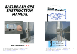
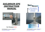
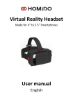
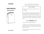
Remote Power
SDT Series
(SDT-SF1024
SDT-SF1524)
Solar Charge Controller
USER MANUAL
Beijing Remote Power Renewable Energy Technology Company
Add:3/F,Huayuan Road
Haidian District
Beijing,China
www.remotepowersolar.com
Contents
1.0 Features…………………………………………........1
2.0 Installation & Operation……………………………2
2.1 Controller Size
2.2 Cable Information
2.3 Battery Cable Connection
2.4 PV Cable Connection
2.5 Load Cable Connection
2.6 Real Picture of PCB Board
3.0 Work Mode Setting………………………………….4
3.1 Mode Setup
3.2 Time Setting Table
4.0 LED Indicator………………………………..............7
4.1 PV Indicator
4.2 Battery Indicator
4.3 Load Indicator
5.0 Specification……………………………………........8
6.0 Problem and Trouble Shooting………………......9
1.0 Features
Control: Micro Controller Unit utilizing dedicated software and SCM for
precise control.
Charging mode: Maximum Power Point Tracking charging allows for high
efficiency boost, recovery and float charging. Temperature compensation
ensures that these parameters are adjusted for maximum battery condition
and hence, prolonged battery life.
Circuit Protection: protection against overload, short circuit and reverse
connection, Built in Transient Voltage Suppression protects against lightning.
Reverse current leakage through PV panel is blocked. Batteries are prevented
from over-charging or discharging.
Full waterproof design: the protection grade IP67.Ensure that the products
can be used under rugged environment.
LED indication: Indicating LED’s, monitor battery charging levels as well as
battery state. LED monitoring of load conditions such as over load and short
circuit as well as load on/off, are also provided.
Infrared Remote Control: Use the infrared programmer can change many
work parameters like the load light control, time control and the charging
voltage etc. it make the product has more extensive applicability
Battery: can apply to lead-acid battery and gel battery, and it also can be set
by user through the custom option
High efficiency: MPPT charge function can accurately track the maximum
power point more than 99%.
1
2.0 Installation & Operation
Attention: Connect battery first,be care of Positive(+) and Negative(-)
2.1 Controller Size
Mount the controller in a suitable place.
Controller Dimensions: 109×114×23.2mm
Installation size:54×105mm
2.2 Cable Information
There are 6 cables(3 red and 3 black) on the controller, 3 red cables are
Positive(PV,Battery and Load), and the black cables are Negative.
2
2.3 Battery Cable Connection
Connect battery Positive and Negative to the controller first to power on
the controller.Make sure correct polarity of terminals.
The controller has protection of reverse polarity,so even not connect
correctly for positive and negative,the controller will not be burned.
2.4 PV Cable Connection
Connect the solar panel to the controller terminals,be careful of Positive and
Negative.when the sun is available in the daytime,the PV indicator will be
green color,otherwise NOT,then you need to check the connection is correctly
or NOT.
2.5 Load Cable Connection
After connected with battery and PV,then connected the Load cable,also be
careful of Positive and Negative,if not connect correctly,it is easily to burn down
the electrical appliances.
2.6 Real picture of PCB Board
3
3.0 Work Mode Setting
The controller is programmed by infrared remote control (RC-DER)
3.1 Key Description
Power ON/OFF: Turn on and off the Remote Control, will turn off
automatically after a period of time no operation .
Controller Switch: Controller manual mode, switch controller load on and off.
When overload or short circuit, troubleshooting first, then press the "controller
switch",controller will return to normal state.
Enter key: go to the next menu level, save with exit.
Return key: to return to the previous menu without saving exit.
Send key: put the written program to the controller. (Only valid in the root
directory)
Receive key: The parameters in the controller were readout and displayed
on the LCD screen.
"
"
∧"
key: page up
:∨"
page
keydown
3.2 Operating procedures brief introduction
4
Set controller models, select the desired parameter setting model.
Depending on the system, adjust the parameters. When finished, press the
Enter key to save.
Press the "send" button to send the setting parameters of remote to the
controller. three lights flash, indicating that the controller programming is
successfully set.
Press the "receive" button to confirm whether the program is set correctly.
3.3 The working mode of the Load
1.Pure light control mode: When there is no sunlight, the light intensity drops to
the start point, the controller confirmation the start signal, 10 minutes after, the
controllers turn on the load and the load began to work;
When there is sunshine, the start point of the light intensity rises above .10
minutes after , the controller output signal to recognition shut off the output ,
thus the load will stop working.
2. Testing Mode: for system debugging using . same pattern with the pure light
control, only cancel the judgment optical signal control output 10-minute delay,
retaining all other functions. Close the load side when there is light signal .
connected the load side when there no light signal . Which is much easier to
check the correctness of the system while installation and commissioning .
3.Manual mode: manually open and close the output load terminals, press the
"controller key" and the load terminals performing
5
4. Automatic mode: When there is no sunlight, the light intensity drops start
point, the controller light control 10 minutes delay start the load, then, the load
start to work. When the load work to the set time load will be off automatically.
the model has dual time function at this time. the first period after dark . the
load start to work till to the set time. Continue for some time , when the
controller comes into the second period . the load will work till reaches the
second set time period, or the light off when the battery voltage is high load.
5.
Setting
Chose the controller mode
Name
First period
Second period
Default
parameter
9
0
Battery type
Parameter Setting
Adjustable
Step
Range
00:00-09:00
00:10
00:00-09:00
00:10
Unit
Note
h
h
Manual/Auto/light
control/Test
Working mode
Optical delay
Light
control
voltage
SDT-SF
SDTL-SF
10
1-60
1
min
5
3.5-10
0.1
V
Lead acid
Gel/lead
acid/custom
You can set any voltage point below when you choose battery type “custom”
Over voltage
protection
17
15-18
1
V
Over discharge
voltage point
11.1
10.5-13
0.1
V
Over discharge
return voltage
point
12.6
11-14
0.1
V
Float charging
voltage
13.6
13-15
0.1
V
Boost charging
voltage
14.6
13-15
0.1
V
6
4.0 Display and LED Indicator
-
Sending port
Receiving Port
Infrared data transmission
Infrared data receiver
Load indicator (yellow) *On - Load On
*Slow flash-Overload
*Off - Load Off
*Flash - Short
\
Battery indicator (yellow orange green)
Red: Over discharge protection
Orange: battery under voltage
Green: battery voltage is normal
·
Slow flash - reaches the charge limit voltage
Battery indicator light (green)
Bright - light battery voltage
Dark - the battery voltage is low light
4.1 PV Indicator
Color
Indication
Working State
Green
On Solid
PV is charging Battery
Green
Flash Fast
Battery Over Voltage,refer to Trouble shooting.
4.2 Battery Indicator
Color
Indication
Working State
Green
On Solid
Battery is Normal
Green
Flash
Battery is full
Yellow
On Solid
Battery is under voltage
Red
On Solid
Battery is over discharge and turn off Load
4.3 Load Indicator
Color
Indication
Working State
Yellow
On Solid
Load is ON
Red
Flash slow
Over Load
7
5.0 Specification
Model
SDT1024SF
SDT1524SF
Rated charging current
10A
15A
Rated load current
10A
15A
System voltage
24V/12V automatically;
Max input voltage of PV
100V
130W@12V
260W@24V
Max input power of PV
Energy
conversion MAX 98%
efficiency
1.25 rated load current 60sec, 1.5 rated loads current 5sec,
Overload,Short current over load protection action. ≥3 Rated load current short
protection
circuit protection action.
≤30 mA
No load current
Charging circuit voltage ≤0.26V
drop
Load circuit voltage drop ≤0.15V
17V,×2/24V;
Over voltage protection
Working temperature
Industry grade:-35 ℃
~+55
℃
Boost charge voltage
(default)14.6V;×2/24V;
(Only discharge condition occur)
Direct charge voltage
(default)14.4V; ×2/24V;
Float charge voltage
(default)13.6V; ×2/24V;
charge return voltage
13.2v; ×2/24V;
Temperature
-5mv/
Lower voltage
12.0V; ×2/24V;
℃
(default)11.1V- real-time modified voltage by the discharge
rat(no load voltage);
return 12.6V;x2/24v
Over discharge voltage
Over discharge
voltage
Charging mode
(MPPT) Maximum Power Point Tracking
8
6.0 Problem and Trouble Shooting
Problem
Trouble shooting
Sunlight on solar panel
but PV charge Indicator
is not on.
Check solar panel output
and cable connections
are correct and connected steady
The PV charge LED
Indicator flashes fast.
System over voltage protection is working.
Open circuit in the battery.
Check battery cable connections.
Charging circuit damaged.
Load LED indicator is on Load open circuit. Check cables and connections
but no output.
and any other load switches.
Load state LED is on
and flashing fast. No
output.
Check output for short circuit or over-load. Remove
the load and switch output ON, Controller will
resume after 30 seconds.
Load state LED is on
and flashing slowly. No
output.
Overload has occurred. Remove sufficient load and
switch output On. Controller will resume in 30
seconds.
System state LED
flashing RED with No
output.
Battery is over discharged and load disconnected.
The load will be reconnected when battery
charged again.
www.remotepowersolar.com
Email:[email protected]
Add:3/F,HuaYuan Road,HaiDian District,Beijing,10088,China
Tel:+86-10-82670382
Fax:+86-10-82257376
9