1
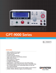
FEATURES
1
1
I
I
I
I
I
I
I
o
1
o
I
I
I
I
I
Operating ‘Joltage {DC} : 'I.5‘U'-~'I 50?
Operating Mode : C.CfC.VfC.RfC.PfC.C+C.VfC.R+C.VfC.P+C.\F
Parallel Connection oflnputs for Higher Capacity [Man 9,-='-ISUW}
Support ofHigh Slew Rate : Max Ifihfps
Run Program Function {Go;'Ho Go Test]
Sequence Function for High Eflicient Lead Simulations
Commands are Compatible With I{ikusui PLZ-4W Model [=*}
Dynamic [Switching] Function : U.D'IE6Hz-2[IkHz
Soft Start Function : Dffffin {'I -—2IJflms, Res : 'Ims}
Adjustable DCPIOKIPIDPPIUKIP Setting
Short Circuit Function
Timer Function: Elapsed Time of Load on
Cut Crfl'Time [Auto Load C’4ffTimer]| : "Is to 999h 59min 59s or Off
External Channel ControlfMonitoring ‘Ilia Analog Control Connector
Set LIP M EI'I"lCl'I'IE5
' I "IOU 5 ets
3.5 Inch TIT LCD Display
Multi Interface: USE 2.0 De\rice]Host, RS-232, GPIB [Dptional]
* The sequence and program commands are different from that of kikusui PLE-4W model-
u
Gt
Reliable
Flexible Power Combinations, High-Speed and Versatile Load Simulations
The PEL-3000 Series, a single-channel, programmable D.C. electronic load with 0.01mA current resolution and 16A/it s current Slew Rate,
is very ideal for testing server power supply and SPS (Switching Power Supply) for commercial and industrial computers. For a heavy-duty
device like cloud ecosystem running 24-hour nonstop operations, a stable and high-power power supply, ranging from 350W to T500\X/, is
required to maintain the normal operation of server, Hub, and the equipment ofdata storage and internet communications. Owing to the
increasing demand of data transmission and large scale data storage of telecommunications systems, the infrastructure of internet
communications is in the pace of rapid expansion. This has greatly boosted the market demand of telecommunications equipment
powered by power supply of 2000\X/ and above. The flexible power combination of PEL-3000 meets the test requirements of present highpower power supply. With respect to battery testing applications such as rechargeable battery for electrical tools, battery module and
automobile battery, PEL-3000 has three stand-alone models to offer including 175W, 350W, 1050\X/ and 1050\X/. By connecting Booster
ZTOOW units with master units, the maximum load capacity of the whole system can reach 9,450W. Hence, the PEL-3000 Series fulfills
various power testing requirements including medium to low power or high-power power supply.
The PEL-3000 Series has seven operating modes and three operating functions. Among the seven operating modes, four ofthem are basic
operating modes, including constant current, constant voltage, constant resistance, and constant power, and the other three are advanced
operating modes including constant current + constant voltage, constant resistance + constant voltage, and constant power + constant
voltage. Users must first select operating mode and then operating function based upon the test requirements. Static, Dynamic and
Sequence operating functions can be applied to different testing conditions including a fixed load level, switching between two levels or
switching among more than two levels. Sequence function is divided into Fast Sequence and Normal Sequence according to the test time
of each step. Both Dynamic and Sequence are to assist users to simulate the genuine load change. For instance, PEL-3000 can simulate
HEV current consumption to make sure that automobile battery can supply HEV with sufficient power need on the road. By so doing,
manufacturers can elevate product quality and reliability.
The adjustable high speed Slew Rate of 16A/it s simulates rise and fall speed of different load current so as to test the adequacy of the
Response time of power supply. The Soft Start function of the PEL-3000 Series can set current rise time for the moment PEL-3000 is
turned on to reduce the abnormal situation ofthe voltage drop of power supply under test. The adjustable Under Voltage Protection (UVP),
GO/NO GO voltage input monitoring function, current monitoring function and Timer Function to control load activation time can be
jointly applied to the characteristic tests of battery bleeding to avoid battery damage during bleeding operation.
Based upon the
functionalities described above, the PEL-3000 Series can test a vast variety of power supply ranging from the fundamental static sink
current to complex dynamic load simulations so as to enhance product quality and reliability.
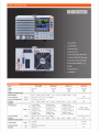
The PEL-3000 Series D.C Electronic Load
The PEL-3000 Series is a high speed, single channel and programmable D.C. electronic load and its power, functionality, parallel
combination and size are listed on the following chart:
Power
175W
350W
1,050W
2,1 00W Booster
Fu|1¢1;i°n
Full-function Single Unit
Full-function Single Unit
Full-function Single Unit
No control panel, can not
be operated alone
Parallel
Parallel Wltl'l-SHITIE
Parallel with-Same
_
_
Combination
model, 5 units the
maximum
model, 5 units the
maximum
Size
Half Rack
Parallel with same model,
Half Rack
5 units the maximum
Parauej
Parallel with the maximum
offour PEL-32115
Full Rack
Full Rack
‘"“'i;1é§fl§§iEfl
-‘._|
I
|
.
-I’
) K‘-;.____;
,--.1
‘\d
“xi
I
1-as-1
I
-
-i_-.
'~.__
~-.
m‘J
-
filgfigiiiiil
Q _
.$;.!_¢-L
<_.--_j____:g_:_.____.
In .__,.- _. i
.-
_
.___;-;.5_11
¢.--_\jf-'.5:-._____!
In _____.__ J I
t_J
._.
-
=
|
5 five
l
'
A
p‘¢aEEe§§i?
.i%e3%e€3§?boieefifinb H
~
Y-— tii-it
P E L- 3 02 1
_
~._‘-_.___.
__ .._§;:_IL
O.-"I?
In L__
I .- ‘
n
.
P E L-3 2 1 1
J.
|
Ll
,
Slave
"—'- ‘
|
‘=8 :3? '- 1 '-
'- -. '-
hfasaefigx
4-._. ___ _. 4.,
k~e§oefi;!
._,.g...__ ____,. 4.,
h-ae£§{}%
._,{._._ ___ _. 4"
~ -'*l'r.-fir.
-3;? - '-. '-
,__
.-.:_-gt;-._.
__>
I.-.'-.W!=:s-ii -l .-lj.-'.,1 I.-.'. wali.ai1i -1tlj.--J l l-w\¥l:féli"‘1£i-li-l l
'
‘@- NEEQHI
I
I
l.._.J
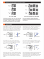
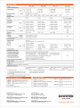
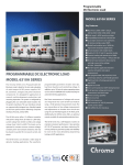
Three PEL-3021 in Parallel
l._.l
One PEL-3'I'I'I connects with two PEL-32'I'I in Parallel
PEL-3000 Series connects with loads via MIL 20-pin interface and
allows users to flexibly select and apply different power
connecting cables to designate a master to control other slave
arrangement which enhances equipment utilization efficiency
units in parallel. One PEL-31 ll and four PEL-321 l s in parallel
to save R&D cost.
provide the maximum power of9,450\X/. Parallel arrangement
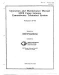
The PEL-3000 series provides four fundamental operating modes
voltage range has two levels - high and low. The load current
and three add-on modes of CC, CR and CP separately combining
with CV. Users can set different load condition under different
operating range has three levels - high, medium and low
current levels which possess different resolution to meet test
operating modes such as setting operating range for load level,
requirements ofdifferent power product specifications.
Current Slew Rate, input voltage and load current. The input
C""’°"t
Current
i’ ' """"" "
V
Source
Voltag (D
-
E-- -
'Z Q I _ Q It
Variable
‘
Variable
0
<
Sou me
Voltag (D
E--._ -
c:
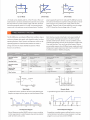
CC Mode
Q
0_
C.R Mode
Under constant current mode, electronic load will sink the
Under constant resistance mode, electronic load will sink load
amount of current users has set. Different current settings via
current, which is linearly direct proportion to input voltage. This
CC mode allow users to test the voltage changes of DC power
supply which is called load regulation rate test.
mode can be utilized in testing voltage or the activation and
current limit of power supply.
current
Variable
current
Q
<
Source
_______ --
QI
Voltagel
Source
0
Voltag
|
C.V Mode
Variable
<
—
Q.
0
I
C.P Mode
Under constant voltage mode, electronic load will sink sufficient
Under constant power mode, electronic load will sink load current,
current to regulate the voltage source to the set value. This mode
which is indirect proportion to input voltage to reach preset
allows users not only to test current limit function of power
constant power requirement. Hence, the changes ofinput voltage
supply, but also to simulate battery operation in testing battery
will have indirect proportion effect on current sinking so as to
chargers.
reach constant power control.
I‘
i
I
Variable
Varia
'%)l e
V
0
F Q
yvariable
V
I
0
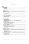
CC+CV Mode
varlabl‘-’\"l
I
V
I
0
CR+CV Mode
I
CP+CV Mode
+CV mode can be selected under CC, CR or CP mode. When +CV
mode function is turned on and electronic load sinks more current
than the maximum current of power supply under test, electronic
load will automatically switch to CV mode. It is because that the
current sunk is the maximum current of power device. Therefore,
power supply will switch to CC mode and PEL-3000 will switch to
CV mode to limit electronic load from sinking the total current of
power supply so as to prevent power supply under test from
damaging. Electronic load will cease operation once the voltage
of DUT is lower than the set voltage under +CV mode.
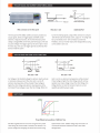
The PEL-3000 series, according to different test conditions, step or
Static function provides a fixed load to test output stability of
power supply. Switching load value A to B will be manually
operated. Under Dynamic function, two test conditions can be
switched automatically and every set of parameter includes Level,
Timer and Slew Rate. Timer can be set to the fastest of 25|Js to
accommodate response time ofdifferent power supply and assist
testing power supply output status when load is unstable in order
to enhance products‘ reliability and quality.
continuous changes, test speeds, and selectable modes, has three
operating functions: Static, Dynamic and Sequence, which can be
separately applied on a fixed load test; between two loads; or
among more than two loads. Detailed descriptions ofthese
functions are as follows:
Operating Condition
Selection
Single fixed
condition
Selection between two
conditions
Selection among more than
two conditions
Selection from more than
two conditions
Operating Modes
All modes
I_ Two
conditions
using same mode
CR’ CCCP
modes
I Each condition must use same mode
I Support CC or CR mode
I Each condition using different mode
I All modes
Adjustable Condition
Setting
I A/B Value
I Slew Rate
I Level l/Level 2
I Timer 1/Timer 2
I Slew Rate l/Slew Rate 2
I Level
I Timer
I Slew Rate
I Others...
I Level
I Timer
I Slew Rate
I Others...
Sequence Step
Combination
N/A
|\|/A
I l Sequence
I 1,000 steps
I 25j.|s/step
I I0 Sequence
I 1,000 steps
I lms/step
Other Functions
N/A
N/A
I Trigger Out function
I Trigger Out function
I Ramp function
Level
Level
Avalue
Sl ew Rt
ae(rise)
'
SI ew Rt
ae(a)
fll
Level 2
B Value
Level 1
:
<iE
mer1 iTimer2 iTimer1 :
Time
Timer2
Timer1
|
D-.
|
| >Time
Dynamic Mode
Static Mode
In Sequence function, waveforms ofload current edited by Fast
Sequence are steps and every step can reach the fastest of Z5|.lS
to provide the high slew rate for electronic loads.
12A —
CCICR
MODE
9A
—
6A
-
3A
I
.
Taro; P
I
|
I-00?!
I
|
LOOPZ
I
|
LOOP3
SET :
TIME:
LOAD :
RAMP:
ax
IIIS
on
on
TRIO:
OFF
|_
_
.
I
LIST Load
Fast Sequence Diagram
Normal Sequence provides RAMP function to users, according
to their requirements, to select between slope and step method
under set time to sink current.
5
I
I05
ax
ss
on
oar
OFF
i
l
-
4.
i 2A
I08
on
on
IA
ss
on
ow
|] ON
OFF
I
ZIIS
I
_
i
I
3A
9A
SS
ON
OFF
ON
|] ON
30$
10$
OFF
OFF
I
I
IIIIS
Normal Sequence Diagram
By applying a complete sequence editing function, users can
control electronic load without using a computer or writing a
program so as to save cost and time of R&D.
Current
Amplitude
I
.._ii
Rated
._
Current
4
in
i i
2 . 15 I
Li
_i _
.
T‘ _ I
i
.
I-I
I
|
E, 5; ,2;
BNC connectors on the front panel
L
-|-R|G OUT
Monitor Output Range
TRIG OUT = ON
The front panel of PEL-3000, via BNC connectors provides two
|M()N QUTPUT
Current monitoring signals, using a BNC connector to compare
output signals, which are Trigger Signal and IMON. Under
with the full scale of real load current, output O ~ lV at high and
Dynamic or Sequence function, the moment the load current
low current levels and 0 ~ 0.lV at medium current level.
setting is changed BNC on the front panel will output a 4.5V and
Therefore, users can monitor load current change without using
2us pulse voltage. This trigger signal can be set to open or close
current probe to save cost.
for every step. Users can use trigger signal to synchronize other
devices inside the system.
V
Voni
V
V out
/
“H;
f/
—
V out
Von
mm
I
> Time
"EL"‘°°°
,
Load otf
j
I
PEL-3000
>Tl'“°
I
>Time
d
Von Latch = OFF
Von Latch = ON
Von Voltage is the threshold voltage for electronic load to activate
Latch is set to on, electronic load operation will be activated
or terminate sinking current. \X/hen Von Latch is set to off,
ifinput voltage is higher than Von Voltage and will continue
electronic load operation will be activated ifinput voltage is
operation even input voltage is lower than Von Voltage. Von
higher than Von Voltage and electronic load operation will be
Voltage function can test the transient maximum current
terminated ifinput voltage is lower than Von Voltage. \X/hen Von
capability provided by power supply.
Load A
Current
wslslz
S3
>
Three different load waveforms of Soft Start Time
Soft Start regulates the time ofcurrent rising from O to preset
speed ofload current. Sudden voltage drop will result in an
value during the moment load is activated. This function is to
unsuccessful activation ofelectronic load or DUT and a
prevent voltage from dropping due to the fast transient rising
damaged DUT.
Adjustable Thresholds
,/
,/
,/
Fixed
./
Load Off
J
J
J
N/A
J
Limit Function
J
N/A
J
N/A
N/A
The PEL-3000 Series provides many protective functions including
function can also be utilized to maintain electronic load in
over current protection (OCP), over voltage protection (OVP),
operation at a preset value. The related settings and selections
over power protection (OPP), over temperature protection (OTP)
are as follows: Take UVP as an example. In battery bleeding
and under voltage protection (UVP). Except for OTP, all thresholds
tests, electronic load will cease operation if battery voltage is
of protective functions are adjustable. When protective function
lower than the set protective threshold value in order to prevent
is activated, electronic load will send out warning signal and
battery from over bleeding.
terminate operation. Other than protective functions, Limit
H.
ANALOG CHANNEL CONTROL
EXT-V
0
-i
Q
Q
-1
S I
v
3 .
. .
-
PEL 3000
::
“ g :
J1 connector
/"_
i.
I
I
-s"
,,. I
—
I
..
.
If
.
E
3.
II‘
ll
I
“
\
/~
_.
\
C Q6,
/ _
7'”
Ferrite Core and
.
. .
twisted wiring
.J
l-9;/\<
_\_ /‘
“
I
3
A
II
.-
Input
Terminals
T‘
External Voltage Connection
Rear Panel
The PEL-3000 Series provides the external analog channel control
is limited to the range of0Q ~ l0kQ; and related to load level are
function, which allows users to connect jl and 12 MIL 20 pin
0~l00%. For instance, when operating PEL-3021 under CC mode
standard connectors on the rear panel to input voltage or to
and 35A, external input voltage is IV and sink current is 3.5A.
connect resistance to control electronic load operation. Input
Users can integrate this function into test system and utilize
voltage is limited to the range of0 ~ IOV; connecting resistance
signals generated from the test system to control PEL-3000 Series.
Cut OffTime I
»- Elapsed Time ]
Elapsed Time
Time Up
Voltage : 5.1223V
Enter
Voltage at Cut Off Time]
Voltage at Cut Off Time
The PEL-3000 series provides count time and cut offtime
this function will start counting time. Electronic load will cease
functions. The display screen will show present activation time
operation (load off) and show the final input voltage on the
screen when preset time is reached. Timer function can provides
when electronic load is activated. When electronic load operation
is terminated count time will stop and the total operation time
will be shown on the display screen.
The activation time ofcut offtime can be set to the maximum
length of999h 59min 59s. When electronic load is activated
information and application related to time. Users can obtain
the total time of limiting electronic load operation to increase
the agility of electronic load tests.
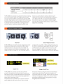
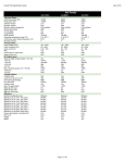
SPECIFICATIONS
PEL-3021
Model
Voltage
1.5V~150V
35A
175W
Current
Power
PEL-3041
PEL-3111
PEL-3211
1.5V~15OV
70A
350W
1.5V~150V
210A
1050W
1.5V~150V
420A
2100W
CONSTANT CURRENT MODE
Operating Range
0~35Al 0~3.5Al 0~0.35A A~7OAl A~7A l A~0.7A A~21OAl A~21Al A~ 2.1A
Accuracy of Setting
H,M,L
i(0.2 % of set + 0.1 % offs“) + Vin”/500 kQ
Accuracy of Setting(ParaIlel)
H,M,L
i(1.2% of set +1 .1% off.s.*’)
Resolution
1mA
l 0.1mAl 0.01mA
2mA
420A
:l:(l .2% of set+1 .1 % off.s)
l 0.2mA l 0.02mA 10mA l 1mAl 0.1mA
N/A
CR MODE
Operating Range
H
Range
M
L
Accuracy of Setting
H,M,L
CONSTANT VOLTAGE MODE
Range
46.6672s~800tis
(21 .428mQ~1 .2s|<o)
4.66675-sous
(214.28mQ~12.5kQ)
0.466675-sits
(2.142so~125|<o)
140.0016S~2.4mS
(7.1427mQ~416.6667 o)
14.0001 S~242.4|.tS
(71 .427mQ--4.1 66671< Q
1.40001 s-24.2405
(714.27mQ~41 .66671< Q
l
4005
l
4 ll S
800).l.S
l
8005
23.00025-484.8115
(35.7135mQ~2.08334Q)
:l:(-l .2% ofset +1 .1% off.s)
i(0.5 % of set“ + 0.5 % offs“) + Vin“/500kQ
400,15
Resolution
Operating Range
23.3336s~400iis
(42.357mQ~2.5kQ)
2.333365--40).IS
(428.566mQ~25l<Q)
0.2333365-4,15
(4.28566Q~250kQ)
l 811$
2.4mS
l
24005
l
2 4 I15
N/A
1.5V-150V
1.5V-150V
1 .5V~15V
1.5V~15V
Accuracy of Setting
|-| 1, |_
i(0.1 % of set + 0.1 % off.s)
Resolution
HIL
10mV/1mV
N/A
Model
PEL-3021
PEL-3041
PEL-3'l'l'l
PEL-3211
CONSTANT POWER MODE
op,,__,,,,,,,g Range
Range
Accuracy ofSetting
H
17.5w-175w
35W»-350W
105w~10s0w
210\x/~2100\x/
M
'l.75W-17.5W
3.5W-35W
'lO.5W-105W
2'lW-ZIOW
L
0.1 75W~l.75W
Q.35W~3.5W
l.Q5W~l O.5W
Z.lW~2lW
H,M,L
i(0.6 % of set is + 1.4 % of f.s*°)
Resolution
10mWl
1mW l O.1mW
10mWl
1mW
l O.1mW
100mWl 10mWl
N/A
1mW
PARALLEL Mode
Capacity
875W
1750W
5250W
PEL-3111 with 4 booster
units: Max 9.45kW
SLEW RATE
Setting Range
(CC mode)
Range
i 2.5mA/|.is~2.5A/|.is
M
250uA/us~250mA/|.is
Range
i 250uA/us~250mA/us
25|.iA/|.1s~25 mA/us
M
25|.tA/l.LS~25I'l’lA/|.tS
Setting Range
(CR Mode)
2.5uA/us~2.5mA/us
Accuracy ofSetting
|-| , M , |_
5mA/us-5A/us
16mA/|.is~16A/us
16mA/(.is~16A/us
500uA/ps~500mA/lis
1.6mA/us-1.6A/us
1.6mA/us~1.6A/|.is
50uA/us~50mA/us
l60l.LA/l1S~l 60mA/us
N/A
500uA/|.is~500mA/j.is
50uA/ps~50mA/us
1.6mA/us»-1.6A/us
160uA/ps~160mA/us
1.6mA/us~1.6A/us
160uA/us»-160mA/|.is
5|.iA/us~5mA/us
16uA/us-16mA/us
0.2uA ~ 2mA
0.6uA~ 6mA
N/A
N/A
N/A
i(10 % of set='<7 + Sus)
Resolution
0.1uA~1mA
METER
Voltmeter
Accuracy
Am meter
Ammeter(Parallel Operation)
Accuracy
Accuracy
i(0.1 % of rdg + 0.1 % off.s)
i(0.2 % of rdg + 0.3 % of f.s)
¢(1.2% of rdg +1 .1% off.s.)
DYNAMIC MODE
Operation Mode
N/A
CC and CR
0.025mS~10mS/Res:1us;1ms~30s/Res:1ms
1|.iS/1msi100ppm
T1 81. T2
Accuracy
Slew Rate
Range
H
M
2.5mA/us~2.5A/|.is
5mA/j,is~5A/us
16mA/us»-16A/|.1s
16mA/us-16A/us
250uA/us~250mA/us
500uA/us~500mA/us
1.6mA/us~1.6A/us
1.6mA/|.is~1.6A/us
25uA/us~25mA/us
50uA/ps~50mA/us
160pA/us~160mA/us
Current Accuracy
PROTECTION FUNCTION
i0.4% F.S.
i0.4% F.S.
i0.4% F.S.
Overvoltage protection(OVP)
Overcurrent protection(OCPI1
Overpower protection(OPP)
Adjustable ; Turns offthe load at 110% ofthe rated voltage
Overheat protection(OH
P)
'
Undervoltage protection(UVP)
'
Turns offthe load when the heat sink temperature reaches 95 °C
Adjustable : Turns offthe load when detected
Can be set in the range of0 V to 150 V or Off
By diode. Turns offthe load when an alarm occurs
Reverse connection protection(REV)
POWER SOURCE
0.03A~38.5A(Adjustable) | 0.06A~77A(Adjustable)
0.1W~192.5W(Adjustable)
0.3W~385W(Adjustable)
N/A
i(1.2%ofset+1.1% of F.S)
0.2A~231A(Adjustable)
1W~1155W(Adjustable)
N/A
AC100V ~ 230V:l:10% ; 50Hz / 60Hz :I: 2H2
INTERFACE
USB/RS232/Analog Control (Standard) ; GPIB( Option)
DIMENSIONS & WEIGHT
214 5(W)x124(H)x400(D)mm;
Approx 6kg
1'r'|_
Full 5¢3le Qf H range _
fr 7 _
214.5 ()
W x124 l)
H x400 ()
D mm;
Approx . 7kg
'
Tlme
to reaeh frgm ‘IO %~9O % when the
*2. . I.
.
.
_
Vin input terminal voltage of electronic load
current is varied from 2 %~100 %(20 %~
100 % in M range) ofthe rated current.
*3. M range applies
' to the full scale ofH range .
""4. Set = Vin/Rset
'
.
,,5_ .
.
. .
. .
It is not applied for the condition ofthe parallel operation
*6. M range applies
' to the full scale ofH range .
ORDERING INFORMATION
QPTIQNAL A55E550R"55
pE|__3o2-|
WSW Programmable DC E|ectmnic Load
GTL-120 Test Lead (Max 40A)
PEI--3041
350W Programmable DC Electronic Load
an-‘Z48 GPlB Cable (Zm)
PE|_.31'|1 mow Prggrammable 13¢ E|e¢(m,,i¢ Load
PEL-3211 2100w Booster unit for PEL-3111 only
429.5 ()
W x128 I)
H x400 ()
D mm; 427.7 I)
W x147.8 l)
H X5925 I)
D mm;
Approx . 17kg
Approx . 23kg
Specifications subject to change without notice.
GRA-413
EL-3000G D1 BH
Rack Mount Kit (EIA+jIS) for
PEl"32ll
GTL-246 use Cable, use 2.0A-B TYPE CABLE, 4P
on-255 Frame Link Cable (300mm)
GRA-414-] Rack Mount Kit (JIS) for PEL-3021/
3°41/3111
ACCESSORHES :
GTL-Z51
ORA-414-E Rack Mount Kit (EIA) for PEL-3021/
User Manual x 1, Power Cord x1
GTL-252 Frame Link Cable (550mm)
Global Headquarters
GPIB-USB-HS (High Speed)
U.S.A. Subsidiary
GOOD WILL INSTRUMENT CO., LTD.
INSTEK AM ERICA CORP.
T +336-2-2263-03 89 F +836-2-2263-0639
T +1 -909-591 8358 F +1-909-5912280
China Subsidia
lap an Subsidia ry
~
GOOD WILL INSTRUMENT (SUZHOU) CO., LTD.
T +86-512-6661-7177 F +86-512-6661-7277
INSTEK ]APAN CORPORATION
T +21-45-476-5650 F +31-45-476-5653
Malaysia Subsidiary
Korea Subsidiary
GOOD WILL INSTRUMENT M SDN. BHD.
GOOD WILL INSTRUMENT KOREA CO., LTD.
'r+604-6309933 i=+6o4-63099s9l l
3°41/3111
T+s2-2-3439-2205 F+s2-2-3439-2207
G i lI'l5l'El(
w
_
.
Simply Reliable
I
www-gwl nstek-com