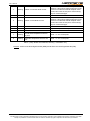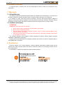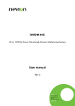
1
CW Fiber Laser User’s Manual Product CRFL Platform M701 UM n°36 – Rev.03 – March 2014 User’s Manual WARNING This product might be a class III-B or class IV fiber laser. Refer to the front panel label (or the lid) of your device. Invisible laser radiation when the product is operating with fiber disconnected. AVOID DIRECT EXPOSURE TO THE BEAM: Never operate with a broken fiber or with fiber disconnected. DO NOT OPEN THE DEVICE, WARRANTY VOID IF THE MODULE HAS BEEN OPENED. BEFORE ANY USE OF THE DEVICE, ENSURE YOU HAVE READ THE USER MANUAL AND SPECIALLY THE SAFETY CONSIDERATIONS. Published on March 2014 UMn°36 – rev.03 2 This document and any information disclosed herein are the property of Keopsys and constitutes and contains proprietary information. Receipt or possession of this document does not confer or transfer any right to duplicate, use disclose any information User’s Manual Table of Content 1. General Information ................................................................. 5 1.1. About this manual .................................................................................................5 1.1.1. Purpose ....................................................................................................................... 5 1.1.2. Prerequisites ................................................................................................................ 5 1.2. General safety considerations .............................................................................5 1.2.1. Terms and symbols in this manual ............................................................................... 5 1.2.2. Terms on the product ................................................................................................... 5 1.2.3. Class III-B Laser product .............................................................................................. 6 1.2.4. Class IV Laser product ................................................................................................. 7 1.2.5. Electric Safety .............................................................................................................. 8 1.2.6. Other safety considerations.......................................................................................... 8 2. Installation and Service ........................................................... 9 2.1. Unpacking ..............................................................................................................9 2.2. Standard accessories ...........................................................................................9 2.3. Installation..............................................................................................................9 2.3.1. Connecting fibers ......................................................................................................... 9 2.3.2. Connect a collimator (optional) ..................................................................................... 9 2.3.3. Cleaning optical connector ......................................................................................... 10 2.4. Power Up ..............................................................................................................10 2.4.1. First time power-up .................................................................................................... 10 2.4.2. Shut down .................................................................................................................. 11 3. Design of the Device .............................................................. 12 3.1. Device overview ...................................................................................................12 3.1.1. Overview .................................................................................................................... 12 3.1.2. PIN assignment.......................................................................................................... 13 3.2. Design of the Device ...........................................................................................14 3.2.1. Optical Design............................................................................................................ 14 3.2.2. Electrical Design ........................................................................................................ 14 3.2.3. Automatic Shutdown .................................................................................................. 15 3.3. Principle of regulation .........................................................................................15 3.3.1. Automatic Current Control (ACC) ............................................................................... 15 3.3.2. Automatic Power Control (APC) – Optional ................................................................ 16 4. Device specification............................................................... 17 4.1. Electrical specification ........................................................................................17 4.1.1. Power Supply ............................................................................................................. 17 4.1.2. Input........................................................................................................................... 17 4.1.3. Output ........................................................................................................................ 17 Published on March 2014 UMn°36 – rev.03 3 This document and any information disclosed herein are the property of Keopsys and constitutes and contains proprietary information. Receipt or possession of this document does not confer or transfer any right to duplicate, use disclose any information User’s Manual 4.2. Mechanical Specifications ..................................................................................17 5. Remote control ....................................................................... 19 5.1. RS232 Protocol ....................................................................................................19 5.2. Commands ...........................................................................................................19 5.3. Mode of operation ...............................................................................................20 5.4. Alarms and Warning description ........................................................................20 6. Human Interface ..................................................................... 22 7. Warranty .................................................................................. 22 7.1. Default Warranty ..................................................................................................22 7.2. Limitation of warranty .........................................................................................22 8. Assistance .............................................................................. 22 Published on March 2014 UMn°36 – rev.03 4 This document and any information disclosed herein are the property of Keopsys and constitutes and contains proprietary information. Receipt or possession of this document does not confer or transfer any right to duplicate, use disclose any information User’s Manual 1. General Information 1.1. About this manual 1.1.1. Purpose This documentation is provided as an instruction manual to Keopsys’ customers and potential customers only. The contents of this publication may not be reproduced in any part without prior written permission of Keopsys. This documentation is provided “as is” without any express or implied warranty of any kind. It includes general safety considerations, optical and electrical connections for installing the product. Keopsys company is committed to conduct its business with the ISO 14000 environmen-tal program. For this, we design our product and service to minimize use of hazardous materials and to enable recycling and re-use. This manual is constituted with matters which can be recycled. 1.1.2. Prerequisites It is assumed that the user is familiar with fiber optic technology and laser safety issues. 1.2. General safety considerations 1.2.1. Terms and symbols in this manual The following terms and symbols may appear throughout this manual: WARNING ATTENTION Warning statements identify conditions or practices that could certainly result in injury. Caution statements identify conditions or practices that could result in damage to this product or other property. 1.2.2. Terms on the product The following terms may appear on the product: DANGER CAUTION ATTENTION Published on March 2014 The label indicates the presence of danger. Indicates an injury hazard not immediately present when you read the label. Indicates a hazard to property, including the product itself. UMn°36 – rev.03 5 This document and any information disclosed herein are the property of Keopsys and constitutes and contains proprietary information. Receipt or possession of this document does not confer or transfer any right to duplicate, use disclose any information User’s Manual 1.2.3. Class III-B Laser product The KEOPSYS products comply with the European and International normalization about laser safety and optical fibers telecommunication systems safety: 825-1 IEC (2007) , EN 60825-1 (2008) 825-1 IEC (2007) , EN 60825-2 (2008) So following symbols appear on the product: LASER WARNING Label (located on the front panel or the lid) EXPLANATORY Label LASER RADIATION WARNING Label (located on the front panel or the lid) ELECTROSTATIC Label (located on the rear panel or the lid) United States Label (located on the front panel or the lid) Class III-B Laser safety: WARNING WARNING WARNING WARNING WARNING WARNING WARNING WARNING Published on March 2014 Class III-b laser product may emit 500 mW max of light in the 1000 nm -1700 nm range. The use of controls or adjustments or performance of procedures other than those specified herein may result in hazardous radiation exposure Use appropriated and standardized laser glasses. The use of optical instruments with this product will increase eye hazard. Do not under any circumstances look directly into the fiber end of an optical cable attached to the optical output while the device is in use.This may cause permanent eye or skin damages and possible loss of eyesight. Disable the laser output before connecting or disconnecting an optical fiber cable on the instrument. Do not open the device. Invisible laser radiation could affect the operator if this condition is not respected. Any check of the optical connectors must be processed when the laser source is unplugged and by using filtering observation optical systems. The device must operate without any impact or vibration. UMn°36 – rev.03 6 This document and any information disclosed herein are the property of Keopsys and constitutes and contains proprietary information. Receipt or possession of this document does not confer or transfer any right to duplicate, use disclose any information User’s Manual 1.2.4. Class IV Laser product The KEOPSYS products comply with the European and International normalization about laser safety and optical fibers telecommunication systems safety: 825-1 IEC (2007) , EN 60825-1 (2008) 825-1 IEC (2007) , EN 60825-2 (2008) So following symbols appear on the product: LASER WARNING Label (located on the front panel or the lid) EXPLANATORY Label LASER RADIATION WARNING Label (located on the front panel or the lid) ELECTROSTATIC Label (located on the rear panel or the lid) United States Label (located on the front panel or the lid) Class IV Laser safety: WARNING WARNING WARNING WARNING WARNING WARNING WARNING WARNING Published on March 2014 Class IV laser product may emit more than 500 mW of light in the 1000 nm -1700 nm range. The use of controls or adjustments or performance of procedures other than those specified herein may result in hazardous radiation exposure. Use appropriated and standardized laser glasses. The use of optical instruments with this product will increase eye hazard. Do not under any circumstances look directly into the fiber end of an optical cable attached to the optical output while the device is in use for this may cause permanent eye or skin damages and possible loss of eyesight. Disable the laser output before connecting or disconnecting an optic fiber cable on the instrument. Do not open the device. Invisible laser radiation could affect the operator if this condition is not respected. Any check of the optical connectors must be processed when the laser source is not supplied and by filtering observation optical systems. The device must operate without any impact or vibration. UMn°36 – rev.03 7 This document and any information disclosed herein are the property of Keopsys and constitutes and contains proprietary information. Receipt or possession of this document does not confer or transfer any right to duplicate, use disclose any information User’s Manual 1.2.5. Electric Safety WARNING WARNING Before connecting your device make sure that the socket outlet is properly grounded Before connecting your device make sure that your line voltage agrees with the voltage given on documentation and sticker on the unit and that the right fuse has been inserted WARNING Before applying power to your device make sure that the protective connector of the 3 conductor mains power cord is correctly connected to the protective earth contact of the socket outlet. Never use a mains power not supplied by KEOPSYS. IMPROPER GROUDING CAN CAUSE ELECTRIC SHOCK with damage to your health and even death. WARNING Never use a unit without its complete package including all covers ; ask if necessary for a replacement part. 1.2.6. Other safety considerations WARNING WARNING WARNING WARNING ATTENTION Published on March 2014 The device has been designed according the standard relative to “Safety requirements for electrical equipment for measurement, control and laboratory use” Do not use the device out of this type of application. The device is designed for an inside application. The device must be properly located on a flat horizontal surface. The device must be located in order to keep free the fan air outlets at the rear of the box. The environmental conditions during the use of the device must comply with those described in the technical specification. UMn°36 – rev.03 8 This document and any information disclosed herein are the property of Keopsys and constitutes and contains proprietary information. Receipt or possession of this document does not confer or transfer any right to duplicate, use disclose any information User’s Manual 2. Installation and Service 2.1. Unpacking The package should be opened in an electrostatic discharge (ESD) free environment. The operator should be properly grounded at the same level as the working surface. The device should be unpacked on an ESD free surface. The laser source electronics and pump diodes can be seriously damaged by electro-static discharge. Even if damage is not immediately apparent, it may shorten the lifetime of the unit, in particular the pump laser. Handle the device with care when unpacking. Hold the box in one hand and the fiber in the other hand when pulling out the unit from its packaging. Lay down the device and the fiber on a horizontal surface. Before any operation, make sure the device is free from mechanical damage, which may have occurred during transportation. The device is supplied by Keopsys completely assembled and tested. Keep the original shipping container for use in case the instrument needs to be returned to Keopsys for repair or servicing. 2.2. Standard accessories The product comes with the following standard accessories: User’s manual (this manual) Test report Interface cable or interface box (optional) 2.3. Installation WARNING WARNING WARNING A professional familiar with optical fiber technology and laser equipment must perform the installation. Before any installation, make sure that you have completely read the general safety considerations. Use appropriated and standardized laser glasses. 2.3.1. Connecting fibers WARNING Invisible laser radiation. Avoid direct exposure to the beam. Direct viewing of the beam may cause serious eye and skin damages and possible vision loss; never operate system with fiber disconnected or a broken fiber. Do not view fiber end directly when optical instrument is powered. Follow the steps to connect optical fiber: 1. Ensure that the device is not powered up. 2. Remove protection caps from optical connectors. 3. The device is delivered with fiber connectors (defined in the technical specification). To connect this device to others equipment, please ensure that the type of connectors is compatible with your device ones. 4. Clean both optical connectors (see §2.3.3). 5. Connect cleaned optical connectors to the device. 2.3.2. Connect a collimator (optional) WARNING Published on March 2014 Invisible laser radiation. Avoid direct exposure to the beam. Direct viewing of the beam may cause serious eye and skin damages and possible vision loss; never operate system with fiber disconnected or a broken fiber. Do not UMn°36 – rev.03 9 This document and any information disclosed herein are the property of Keopsys and constitutes and contains proprietary information. Receipt or possession of this document does not confer or transfer any right to duplicate, use disclose any information User’s Manual view fiber end directly when optical instrument is powered. Follow the steps to connect optical fiber: 1. 2. 3. 4. Ensure that the device is not powered up. Remove protection caps from optical connectors. Clean the optical connector (see §2.3.3). Connect cleaned optical connector to the collimator. 2.3.3. Cleaning optical connector WARNING Make sure the device is switched OFF. With lint-free paper: Use lint-free paper Fold it into a corner Drop the paper into ethanol Clean delicately the polished surface of the connector in a circular motion Blow dry air in order to remove any remaining dust With optical Fiber Connector Cleaner (CLETOP) *: See user instruction enclosed with Cletop cleaner Make sure that the connector does not touch any surface when connecting it. Check with a fiber connector microscope Available at Keopsys: * Connector Cleaner CLETOP. Order with reference CS-OUT-028-00 to your sales contact. For spares patch cords, contact our sales team. 2.4. Power Up 2.4.1. First time power-up To power up the device, you should follow those steps (see §3 for device elements location): Check the device is on heat sink at least. Plug the interface cable to the device. Check the 0/1 button is on 0 position Plug the interface cable to the supply (see §4.1 for specifications) Switch on the power supply Connect the sub-D9 connector to the computer Start the remote control software (see its own manual) Connect the output pigtail to a powermeter or bolometer device which can support laser nominal power (see device test report). Beware of the cleaning of the optical connector (see §2.3.3). Make sure that the connector surface is carefully cleaned. Do not operate the laser with a damaged connector. 9. Switch on your optical source. 10. Turn on the 0/1 button on interface cable. Beware the device is now emitting. 11. Select the ACC mode on remote control software, and set the current to the nominal current (see device test report). Then start the device on remote control software. 1. 2. 3. 4. 5. 6. 7. 8. Published on March 2014 UMn°36 – rev.03 10 This document and any information disclosed herein are the property of Keopsys and constitutes and contains proprietary information. Receipt or possession of this document does not confer or transfer any right to duplicate, use disclose any information User’s Manual 2.4.2. Shut down To shut down the device, you should follow those steps: 1. 2. 3. 4. Turn off the 0/1 button on interface cable. Switch off the power supply. Unplug and protect optical connector. Unplus interface cable. Published on March 2014 UMn°36 – rev.03 11 This document and any information disclosed herein are the property of Keopsys and constitutes and contains proprietary information. Receipt or possession of this document does not confer or transfer any right to duplicate, use disclose any information User’s Manual 3. Design of the Device 3.1. Device overview 3.1.1. Overview 2 1 3 N# 1 2 3 4 Designation Power supply Laser caution Control Optical Output Published on March 2014 4 Description Sub-DW connector. See §3.1.2 for more information. European and US label about laser class and power Sub-D25 connector. See §3.1.2 for more information. Output pigtail UMn°36 – rev.03 12 This document and any information disclosed herein are the property of Keopsys and constitutes and contains proprietary information. Receipt or possession of this document does not confer or transfer any right to duplicate, use disclose any information User’s Manual 3.1.2. PIN assignment Sub-D25 (male): Pin # 1 2 3 4 5 6 7 8 9 10 11 12 13 14 15 16 17 18 19 20 21 22 23 24 25 Designation RS-232 RX RS-232 TX Not used Not used Not used Not used GND Not used Not used Not used Not used Not used Not used RS-232 GND Not used Not used Not used Not used Not used Output Power Disable Description Serial Input for RS-232 protocol. See §5 for specifications Serial Output for RS-232 protocol. See §5 for specifications GND for serial transmission. TTL Input. High level disables laser emission. See §4.1.2 for specifications Not used Not used Not used Not used Not used Example of interface cable: Published on March 2014 UMn°36 – rev.03 13 This document and any information disclosed herein are the property of Keopsys and constitutes and contains proprietary information. Receipt or possession of this document does not confer or transfer any right to duplicate, use disclose any information User’s Manual Sub-DW (female): Pin # 1 2 Designation Ground Power Supply Description Ground for power supply. Device power supply. See §4.1.1 for mor information. Example of interface cable: 3.2. Design of the Device 3.2.1. Optical Design Raman Laser Output Connector 3.2.2. Electrical Design Power supply Sub-D25 Sub-DW Electrical Control Raman Laser Data Output Optical path * Optional Published on March 2014 UMn°36 – rev.03 14 This document and any information disclosed herein are the property of Keopsys and constitutes and contains proprietary information. Receipt or possession of this document does not confer or transfer any right to duplicate, use disclose any information User’s Manual 3.2.3. Automatic Shutdown To prevent any damage on the device we have implement some automatic shutdown. When one of these conditions is activated, the device immediately shutdown and cannot be start up while the problem is not solved. Description Loss of input power Loss of output power Feedback power Case temperature too high First stage diode temperature is out of range Second stage diode temperature is out of range Activation condition Power If input power is lower than keopsys configuration If outpout power is lower than specification If feedback power is higher than keopsys configuration Temperature If case temperature is upper than 65°C If first stage diode temperature is upper than 40°C or lower than 15°C If second stage diode temperature is upper than 40°C or lower than 15°C Availability Only if input monitoring is present Only if output monitoring is present Only if feedback monitoring is present All devices Only if first stage diode is temperature contoled Only if second stage diode is temperature contoled 3.3. Principle of regulation The device offers several modes of operation: Automatic Current Control (ACC) Automatic Power Control (APC) – Optional The ACC mode is available on all devices. The availability of other modes depends on the device, see device’s test report or specifications for more information. Following paragraphs describe these modes and the way that the electrical board drives the pump diodes. 3.3.1. Automatic Current Control (ACC) In Automatic Current Control mode, the laser is controlled from the diodes current set point. The device is running in order to maintain a constant current through the pump laser diodes. A variation of internal optical parameter (due to temperature for example) will induce a variation of output power. The maximum current of pump diodes is indicated on product test report. Current Set Point Laser Output Power Pump Current Published on March 2014 UMn°36 – rev.03 15 This document and any information disclosed herein are the property of Keopsys and constitutes and contains proprietary information. Receipt or possession of this document does not confer or transfer any right to duplicate, use disclose any information User’s Manual 3.3.2. Automatic Power Control (APC) – Optional In Automatic Power Control mode, the laser is regulated at a fixed output power set point. The device is running in order to maintain a constant optical output power monitored with a photodiode. The current of the pump laser diode is adjusted to drive a constant output power. Depending of the number of pump laser diodes, electronic regulation is quite different for one pump diode and two pump diodes configuration. The maximum output power set point is indicated on product test report. Power Set Point Laser Output Power Pump Current Published on March 2014 UMn°36 – rev.03 16 This document and any information disclosed herein are the property of Keopsys and constitutes and contains proprietary information. Receipt or possession of this document does not confer or transfer any right to duplicate, use disclose any information User’s Manual 4. Device specification 4.1. Electrical specification 4.1.1. Power Supply DESIGNATION Comment MIN TYP MAX UNITS Power Supply Voltage Positive power supply 11 24 25 V Parameter MIN TYP MAX UNITS 4.1.2. Input DESIGNATION Type Output Power Disable TTL Low Level 0 - 0.5 V High Level 2.5 3.6 5 V Internal Pull up @ 3.6V - 1k - Ohms 4.1.3. Output No electrical output is available on this device. 4.2. Mechanical Specifications Fig. 1: Device Overview Published on March 2014 UMn°36 – rev.03 17 This document and any information disclosed herein are the property of Keopsys and constitutes and contains proprietary information. Receipt or possession of this document does not confer or transfer any right to duplicate, use disclose any information User’s Manual Fig. 2: Front view Fig. 3: Side view Fig. 4: Top view Published on March 2014 UMn°36 – rev.03 18 This document and any information disclosed herein are the property of Keopsys and constitutes and contains proprietary information. Receipt or possession of this document does not confer or transfer any right to duplicate, use disclose any information User’s Manual 5. Remote control This section describes the serial communication with the device. All information refers to the firmware version 2.41, if your device has a different firmware version, some differences may happen. 5.1. RS232 Protocol To be able to communicate with the device you have to configure the RS232 connection like: Parameter Baud rate Number of bits Stop bit Parity Handshaking Value 19200bps 8bits 1 None None 5.2. Commands The following commands are available for the device: RS232 Commands Cmd. Description Nb Char Example Ex. Answer Unit Information Global Commands SNU? Read Serial Number 7 SNU? SNU=1234567 VER? Read Firmware Version 9 VER? VER=6.5/V2.41 ASS? Read the control mode 1 ASS? ASS=1 ASS= Write the control mode 1 ASS=1 ASS! TCR? Read the case temperature 4 TCR? TCR=2500 PNO? Read the nominal output power 2 PNO? PNO=30 RKP=1 Recover factory settings RKP=1 RKP! See §4.3 1/100°C dBm Monitoring PUE? IC1? IC1= ID1? TD1? IC2? IC2= ID2? TD2? Read the actual input power Read the preamplifier diode current set point Write the preamplifier diode current set point Read the actual booster diode current Read the actual preamplifier diode temperature Read the booster diode current set point Write the booster diode current set point Read the actual booster diode current Read the actual booster diode temperature 4 PUE? PUE=1000 1/100dBm or mW 4 IC1? IC1=1000 mA 4 IC1=1000 IC1! mA 4 ID1? ID1=1000 mA 4 TD1? TD1=2500 1/100°C 4 IC2? IC2=6000 mA 4 IC2=6000 IC2! mA 4 ID2? ID2=6000 mA 4 TD2? TD2=2500 1/100°C CPU? Read the output power set point 3 CPU? CPU=300 1/10dBm CPU= Write the output power set point 3 CPU=300 CPU! 1/10dBm Published on March 2014 UMn°36 – rev.03 Optional Optional If preamplifier diode is cooled See test report for maximum value If booster diode is cooled See test report for maximum value 19 This document and any information disclosed herein are the property of Keopsys and constitutes and contains proprietary information. Receipt or possession of this document does not confer or transfer any right to duplicate, use disclose any information User’s Manual PUS? Read the actual output power 4 PUS? PUS=3000 1/100dBm or mW Alarms & Security ALA? Read Alarms KEY? 4 ALA? ALA=ABCD Hexa See §4.4 1 KEY? KEY=1 0/1 0 = OFF; 1 = ON 0/1 0 = OFF; 1 = ON PUMP? Read state of pump 1 PUMP? PUMP=1 ASI? Read the automatic shutdown threshold for low input power 3 ASI? ASI=-5 dBm Optional ASF? Read the automatic shutdown threshold for high feedback power 3 ASF? ASF=5 dBm Optional The electrical board answer is ended by: ! OK * Command unknown # Not authorized 5.3. Mode of operation Mode of operation meaning Value Name Description 0 OFF Pumps diodes are off. Attention: it doesn't mean that laser emission is disabled. 1 ACC Automatic Current Control. See §2.4.1 for more information. 2 APC Automatic Power Control. See §2.4.2 for more information. Optional 5.4. Alarms and Warning description The answer returned by ALA command is an hexadecimal value of 4 characters. You have to convert it in binary and read the activated alarms using following table: Alarms meaning Bit N# 15 14 13 12 11 10 9 8 Type Description Warning Pumps are disabled Alarm Loss of output power Alarm Loss of input power OR High feedback power "ON" conditions When pumps are off The output power is too low compared with the actual pump diode current Warning Case temperature out of range Second diode temperature out of Alarm range Warning Second TEC current is too high Alarm First diode temperature out of range The input power is too low compared with the input power threshold OR the feedback power is too high compared feedback power threshold. Temperature > 85°C Value < 15°C or Value > 40°C Value < 15°C or Value > 40°C Warning First TEC current is too high Published on March 2014 UMn°36 – rev.03 20 This document and any information disclosed herein are the property of Keopsys and constitutes and contains proprietary information. Receipt or possession of this document does not confer or transfer any right to duplicate, use disclose any information User’s Manual 7 Warning Problem on second diode current 6 5 Not used Warning Problem on first diode current 4 3 Instantaneous current < 8/9 of set point. Attention : this warning appear when the pump emission is enable but should disapear when current has reach the set point. If the warning stay On contact Keopsys. Instantaneous current < 8/9 of set point. Attention : this warning appear when the pump emission is enable but should disapear when current has reach the set point. If the warning stay On contact Keopsys. Not used Alarm 2 Key Off Key on front panel is on 0 position Not used 1 Warning Second diode temperature far from set point Value > +/- 2°C of set point 0 Warning First diode temperature far from set point Value > +/- 2°C of set point Alarm = pump diodes are shutdown; Warning = Information only Remark : bit #15 is the Most Significant Bit (MSB) and bit #0 is the Least Significant Bit (LSB). Published on March 2014 UMn°36 – rev.03 21 This document and any information disclosed herein are the property of Keopsys and constitutes and contains proprietary information. Receipt or possession of this document does not confer or transfer any right to duplicate, use disclose any information User’s Manual 6. Human Interface An optional cable or interface box can be provided with the device. Refer to its manual for more information. 7. Warranty 7.1. Default Warranty This Keopsys product is guaranteed against defects in material and workmanship for 12 months from the date of shipment. Keopsys will either repair or replace products that prove to be defective. For warranty or repair, return this product to Keopsys. The buyer will prepay shipping charges to Keopsys, and Keopsys will pay shipping to return the product to the buyer. However, the buyer will pay all shipping charges, duties and taxes for products returned to Keopsys from any foreign country. 7.2. Limitation of warranty ATTENTION WARRANTY VOID if the device is opened Never use the device to application not described in this manual. Never open or modify the product. Use the device with properly cleaned connector (refer to safety recommendations when cleaning the fiber connectors). Store and use the device in an ESD free environment for unpacking, assembly, maintenance and shipment for warranty. The foregoing warranty will not apply to defects resulting from abuse, misuse, neglect, improper installation or application by the buyer. Keopsys will not be responsible for the damage caused to the device as a result of employing dirty or incompatible fiber connectors. 8. Assistance Should a problem occur, contact Keopsys. A Return Material Authorization (RMA) number will be issued for any faulty unit that needs to be returned. Note this number on the shipping container and on all correspondence. For assistance, or before any shipments, please contact Keopsys: Published on March 2014 UMn°36 – rev.03 22 This document and any information disclosed herein are the property of Keopsys and constitutes and contains proprietary information. Receipt or possession of this document does not confer or transfer any right to duplicate, use disclose any information