1
Hl l l l l l l l l l l l l lgLl l l lLwl l l l l l l l l l l l l l l
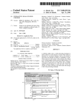
United States Patent {19]
[11]
Patent Number:
Gurne et a1.
[45]
Date of Patent:
[54] HAND HELD AUTOMOTIVE DIAGNOSTIC
SERVICE TOOL
[75] Inventors: Krzysztof Gurne, Warren; Raymond J.
Williams, Farmington Hills; John R.
Boldt, Troy; Robert L. Barker, Auburn
5,003,476
3/1991
5,003,477
3/1991 Abe et a1. ..
10/1991 Stewart et a1. .
364/55l.01
5,077,670
12/1991 Takai et a1. .............. ..
364/424.03
Mich.
364/551.0l
Field of Search ....................... .. 364/424.03, 424.04,
364/550, 551.01; 73/1173, 117.4, 118.1;
340/438, 459; 371/291
References Cited
4,602,127
7/1986 Neely et al.
4,694,408
9/1987
4,831,560
5/1989 Zaleski .............. ..
364/55l.01
4,853,850
8/1989 Krass, Jr. et al. ..
364/424.04
4,866.616
4,962,456
9/1989 Takeuchi et al.
10/1990 Abe et al. ......... ..
..... .. 364/424.04
364/42403 X
4,964,049
10/1990
. . . . . ..
4,975,846
4,975,847
12/1990 Abe et a1. ..... ..
364/424.03
12/1990 Abe et al. ........................ .. 364/424.03
...... ... ...
Abe et a1.
.. .....
Chrysler Reference Manual for Snap-On Scanner and 1990
Supplement.
Primary Examiner—Collin W. Park
Attorney, Agent, or Firm-Mark P. Calcaterra
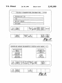
[57]
ABSTRACT
diagnosing and isolating problems and for monitoring oper
5/1984 Hosaka et al. ................... .. 364/424.04
11/1980 Kinoshita et al. .... ..
364/424.03
3/1983 Kato et a1. ................... .. 364/424.03
Zaleski
book.
MPSI Pro—Link 9000 Manual for Chrysler System. 1988.
The present invention relates to a system and method for
U.S. PATENT DOCUMENTS
Re. 31,582
4,234,921
4,375,672
Chrysler 1983-1988 Instruction Manual, OTC Tool &
Equipment Division Sealed Power Corporation, Feb. 1988,
Equipment Division SPX Corporation, Apr. 1990, entire
Jun. 25, 1993
Int. Cl.6 ............................................ .. G06F 17/40
US. Cl. ................................... .. 364/424.03; 73/1181;
[56]
364/424.03
7/1992 Takai et al. .............. ..
364/42403
11/1994 Schaller et a1. .................. .. 364/424.03
entire book.
1990 Domestic 3 in 1 Monitor 4000B Manual, OTC Tool &
[21] Appl. No.: 83,050
[58]
4/1992 Bethencourt et a1.
364/424.03
OTHER PUBLICATIONS
[73] Assignee: Chrysler Corporation, Auburn Hills,
[51]
[52]
Abe .............. ..
364/424.03
5,058,044
Mich.
[22] Filed:
Abe .................................. .. 364/424.03
10/1991
5,132,905
5,365,436
Hills; Gregory J. Broniak, Oxford;
Jul. 30, 1996
5,056,023
5,107,428
Daniel J. Marus, Rochester Hills, all of
5,541,840
364/43103 X
. . . . . ..
364/551.01
ting conditions on an automobile. The system includes a
hand held unit and a master station which can operate alone
or in unison to accomplish functions such as logging and
displaying data on a real-time basis, logging data remotely
and displaying the data at a later time, diagnosing fault
conditions, monitoring operating parameters, reprogram
ming on-board vehicle controllers, displaying service
manual and service bulletin pages and ordering parts on
line.
364/551.01
8 Claims, 14 Drawing Sheets
US. Patent
Jul. 30, 1996
Sheet 1 of 14
5,541,840
U.S. Patent
Jul. 30, 1996
Sheet 2 0f 14
a +
féli M’
‘2
48
f) )
5,541,840
US. Patent
Jul. 30, 1996
START.‘
USER SELECTS
UPDATE SOFTWARE
Sheet 4 of 14
MDS
'
5,541,840
‘
7
PRESENT
PROGRAM
FROM MOs
?
N0
MEMOR
YE
PROGRAM FROM
MEMORY CARD
CARD PRESENT
PRESEN
PROGRAM
USER SELECTS
MDS (PRESENT)
USER SELECTS
'
MEMORY CARD
MENU
F’g'”
(PRESENT)
POST
60
\C STAND-ALONE MAIN MENU
64
x
~62
\_/ . VEHICLE OIAOMOsTIcs/
UIAL'M
.
VEHICLES SUPPORTED
. HOW TO USE DRB n1
. UPDATE SOFTWARE VERSION
. UPDATE VEHICLE CONTROLLER
\f?p
KG
{} A
p
63/
W/72
O
J
86‘
as
aé'?'iil i/ER SE15; *5?) 80
I.E.
UP/DOWN
74__/HELP
TOGGLE
»
TURN
5T0
UN/OFF
BACK LIGHT/73
DISPLAY
76
Fig-5
US. Patent
Jul. 30, 1996
K
Sheet 5 of 14
STAND-ALONE MAIN MENU
1.
2.
a.
4.
\
ECHO 0N
[E ON
DMM SPLI
moow
OFF m
DISPLAY UNITS
@ METRIC
KEY
EAT
OFF m
5. KEY
6. KEY FEE
CK L
CK 8
OFF
OFF
ON
ON
7. DATE
1/30/92
8. TIME
.- 25 P.M.
@m
G
6*
@
C15}
{-15}
CF?)
I.E.
UP/DOWN
TOGGLE
L
HELP
@
J
CF33
TURN
STOP
ON/OFF
BACK LIGHT
DISPLAY
/ STAND-ALONE MAIN MENU
mw a »
5,541,840
.
.
ENGINE
TRANSMISSION
.
.
BODY
.
.
.
ANTI-LOCK BRAKES
PASSIVE HESTHAINTS
THEFT ALARM
"7
\
SUSPENSION
SYT T M MONIT
CLI
E CONTR
K?
{P
@
E
@j
LE1;
LE2}
{f3}
LE4)
TURN
ON/OFF
STOP
I.E.
HELP
UP/D
TDGG
BA
LIGHT
PLAY
- "6
US. Patent
O
L
Jul. 30, 1996
Sheet 6 of 14
vEHICLE DIAGNOSTICS INFORMATION
TECHNICIAN
VIN:
.
.
.
REPAIR
.
.
.
.
.
OROER:
MILEAGE:
F3
.
IO.-
.
.
.
.
.
5,541,840
‘I 011!
W
. . . . ..
.
.
.
.
.
.
.
.
.
.
.
.
.
.
.
.
.
..
MOOE
..
NO
HELP (MORE)
YES ATM- v/O
MP ‘DOWN @255
ENTER
\
J
MOOE
(MORE)
MAIN
F6
MEN PRINT
F11
F12
g?gg ‘ERIE
‘ F1947
lcHRYsLER MOPAR OIAONOsTIC SYSTEM MAIN MENOT O 1
DIAGNOSTICS
TECHNICAL
SYSTEM
MENU
suPPORT
INEOQHAFTION
gg?ls
SYSTEM
TRAINING
CATALOG
F3
MOOE <-P1 <—F2 tNO
L YES
UP DOWN
HELP (MORE) LEFT RIGHT
\
V[0—
NtXT
MENU
J
F3
MOOE
HELP (MORE)
F6
PRINT
US. Patent
Jul. 30, 1996
Sheet 7 0f 14
5,541,840
»
+
+
+| | J
+
US. Patent
Jul. 30, 1996
Sheet 8 of 14
5,541,840
/
)
CHRYSLER MOPAR DIAGNOSTIC SYSTEM FAULT SELECTION XXX]
INSTRUCTION
TO SELECT A DIAGNOSTIC TEST FOR FAULT (S) SHOWN
AT RIGHT
.U ENTER THE FAULT NUMBER.
(1 FOR FIRST FAULT, 2 FOR SECOND FAULT. . .)
2) THEN PRESS THE 'F2 ' KEY
ENTER '90’ TO REDISPLAY FAULT DATA.
OTHERWISE, TO SELECT A DIAGNOSTIC TEST FOR
SPECIFIC SYSTEMS OR SYMPTOMS.‘
ENTER '0' (ZERO). THEN PRESS THE 'F3' KEY
FAULT 1 OF 1
START/RUN COUNT = 1
MAP VOLTAGE TOO HIGH
SELECT TEST <XX>
F3
MODE <—F1 +F2
HELP (MORE) LEFT RIGHT
Fig - /0
US. Patent
Jul. 30, 1996
Sheet 9 of 14
5,541,840
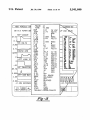
TEST IOAI REPAIRING PASSENGER SIDE TIME LIMIT EXCEEDED
Per-Form TEST 1A BeFor-e Proceeding
PASSIVE
BELT
CONTROL
MODULE
High? Sea? Bel+ Man»- Reverse. Driver
6
High‘? Sea‘I’ Bali’ Mo'for Forward Driver
IO
RD
Fused B b’)
M
MOTOR
TO
BATTERY
FIG "2
C
C
MISGm OYBRLW KDB
R
GF
W
RIGHT
SEAT BELT MOTOR RESERVE DRIVER
w.
m
E
)
RIGHT SEAT BELT MOTOR FORWARD DRIVER
FIG-3
my -//
U.S. Patent
I
Jul. 30, 1996
MDS VEHICLE DA
92 8.0 VIPER SB
Sheet 11 0f 14
5,541,840
FRAME: +0
TIME:
8-91
gg‘dgc UP AND
RPM
0
RPM
L-LT
o
%
g7_5
L-IJ
0.000
MSEC
0. 1
~)\__ 5105
R-IJ
MAP VACUUM
TPS VOLTS
‘$2.,
02000-03
+0000
E)
"
$115 3.000
8.51 VOLTS
%E15 g0.8.00., LL11“
‘
R-LT
8'000 QSEC
LTD
54
USEC
O_71___________J"
H__02
DIS
8.47
_8
VOLTS
__ ‘F522
5%,
5047
g9}: a“:
ENGINE RPM
BAHO
293
IN H6
2E?‘
:01’ w:
TPSC
0.71
VOLTS
§§? 313? E5’?
0 N ‘2515
‘1.15
12E:
_ TUI- 211
704 m1
LEFT LONG TE 5%”
‘26?
52??
g. g; ".53
3.80
RTD
3278
3
Egg 8-“ 535%
n-u
5%
3'°°° :85“
“
“SE”
l
IAT
IATv
@QET
118
DEG F
Eé?
LEF INJECTOR
TLDL
59
STEPS
0&6 "'1 cm
0.000 __J\______'_
V55
2.3L
0
OFF
1.00
2.35
BRAK
ALL GEARS
RELEASED
0m
W 00
UMP
~15
LEFT 02S BAN
—0. 184 SECONDS A59
CKP
F3
MODE <-
HELP (MORE) LEF
VTAi
vTAg
1.41
12.5
VOLTS
VOLTS
w
5'0’ {PM
% '&
124 021
MPH
BLOCKED
WW
?g
OFF
+44.717SECONDS
FUEL
SEEN
TROUBLE CODES/COUNTS
\
3
u
)
lFl'g-B
5,541,840
1
2
HAND HELD AUTOMOTIVE DIAGNOSTIC
SERVICE TOOL
manifesting itself. However, this is di?icult to achieve
because the technician cannot easily drive around with the
BACKGROUND OF THE INVENTION
customer and the customer cannot afford to leave the vehicle
with the technician for days at a time. For the technician, it
is often expedient to simply replace parts which seem to be
1. Field of the Invention
This invention relates generally to a system and method
the likely culprits in the hopes that the tried-and-true method
will solve the problem. However, this increases warranty
for monitoring automobile operating parameters and for
costs to the manufacturer, because parts that may not be
diagnosing operational errors, and more particularly to a
faulty are replaced regardless. Also, when parts are replaced
and the problem still remains, the customer become frus
system and method for retrieving diagnostic codes from
automotive control systems, for monitoring automotive
trated and often vents this frustration on dealership person
operating parameters, for performing diagnostic inquiries,
nel. Therefore, it would be preferable if tools were provided
to the technician which improves his ability to monitoring
problems as they occur and to accurately diagnose and repair
and for logging and later downloading operational variables.
2. Description of the Related Art
In the ?eld of automotive service, it has become increas
ingly important to be able to monitor the operation of major
automobile systems, such as the engine, transmission and
braking system, on a real-time basis for diagnosing and
15
features would prove very helpful.
repairing operational problems. Since these major systems
SUMMARY OF THE INVENTION
are now usually controlled, either entirely or in part, using
an microcomputer, the on-board ability of the controllers to
It is therefore an object of the present invention to provide
a system and method for monitoring the operation of a
vehicle on a real-time basis, and for providing sophisticated
store operational information and error codes for later
retrieval has been exploited to improve the accuracy with
problem solving capabilities for accurately diagnosing and
which service personnel diagnose problems. However, these
controllers have limited on~board memory for storing these
operation parameters. Moreover, relying solely upon on
board capabilities does not allow the service procedures to
adapt to information learned after the product has been out
in the ?eld for a while. Thus, it is preferable to supplement
25
service support and capabilities. The scan tool of the present
invention is adapted to interface to the automobile and
communicate with the various on-board controllers to moni
tor the operation of the vehicle on a real-time. The scan tool
is adapted to be compatible with a wide variety of makes and
models of automobiles and vehicle systems, reducing the
commonly known as a “scan tool.” The scan tool is typically
need to replace scan tools as model years change. The scan
hand-held and interfaces to the automobiles on-board con
tool can be updated quickly and easily from the master
trollers via the vehicle communication bus, usually tapping
station or from memory cartridges. The master station of the
present invention is adapted to interface to the scan tool and
in to the bus at a connection point located beneath the
dashboard. For a scan tool to be a truly effective aid in
diagnosing problems, the scan tool must be able to commu
provides sophisticated updating and diagnostic capabilities
not feasible to include in the scan tool itself. The master
nicate, or “talk,” to the various on-board controllers, regard
less of whether the controller is manufactured by the auto
station reduces the need to rely upon printed service manuals
when using the scan tool, reducing printing and distribution
mobile manufacturer or a supplier company.
costs. The scan tool is further adapted to provide data storage
capabilities, allowing the status of monitored operating
parameters to be logged and downloaded later for inquiry.
The master station can plot and interpret vehicle information
45
for use on different vehicles is undesirable for reasons of
from the scan tool, whether real-time or logged, to aid the
technician in diagnosing the cause of a problem.
One advantage of the present invention is that it is suited
cost, limited storage space and dii?culty for the service
technician in remembering how to use each of these different
scan tools. Most currently available scan tools also rely upon
fault trees printed in service manuals for guiding the tech
for use in conjunction with a wide variety of automobiles
and automotive controllers, reducing the need to replace
scan tools as model years change and reducing the need to
carry several different scan tools for communicating with
nician through diagnostic steps. These printed service manu~
different controllers. Another advantage of the present
invention is that the logging capabilities allow the technician
als are costly to prepare and distribute, and become soiled
and torn through repeated use. The manner in which these
service manuals are supplemented is often problematic,
because these manuals are usually bound volumes and do
not permit the easy substitution of updated pages.
A concern of service personnel and automobile manufac
turers alike is the need to ensure problems are diagnosed
repairing problems. The present invention employs a hand
held scan tool and a master station to provide improved
on~board capabilities with auxiliary diagnostic systems.
One commonly employed auxiliary diagnostic system is
One disadvantage of currently available scan tools is their
inability to accommodate a wide variety of automobile
models without requiring substantial hardware or software
modi?cation. For most dealerships or service stations,
requiring the service technician to stock different scan tools
the cause of the problem. Since scan tools are fairly familiar
to technicians, a scan tool which provides these added
or the customer to drive the automobile while monitoring
55
accurately and promptly. For the service technician, the
and recording operation parameters as the problem occurs.
Still another advantage is that the master station allows the
scan tool to be updated quickly without requiring new scan
tools to be purchased when service information is updated.
Another advantage is that the master station reduces the
reliance upon printed service manuals and loose page ser~
customer who brings the vehicle in for service often has a
vice updates.
very vague description of the problem (“it makes a clickity
noise sometimes”) that is not currently manifesting itself
when the vehicle is brought in and that the technician ?nds
BRIEF DESCRIPTION OF THE DRAWINGS
difficult to recreate. It would be easier for the technician to
accurately diagnose the cause of a problem if he can monitor
the operating conditions of the vehicle while the problem is
Other objects, features and advantages of the present
invention can be appreciated by referencing the following
description of the presently preferred embodiment in con
5,541,840
3
4
junction with the drawings, where:
inches tall and weighs approximately 4 lbs. The face of the
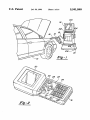
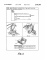
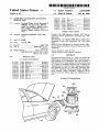
FIG. 1 is an illustration showing how the scan tool
interfaces to the automobile and master station;
FIG. 2 is an orthogonal illustration of the appearance of
the scan tool;
FIG. 3 is a plan illustration of the appearance of the back
of the scan tool;
hand held unit includes a display screen 20 and a keypad 22.
The display screen in this embodiment is a backlit LCD
display having a resolution of 320x200 pixels, with an
overall screen dimension of 4 inches wide by 3 inches tall.
The screen is tilted at a slight angle to facilitate viewing
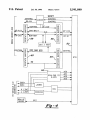
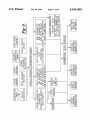
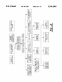
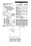
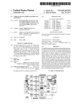
FIG. 4 is a block diagram representing the architecture of
the hand held unit;
is formed from a ?exible plastic membrane with the key
boundaries 23 embossed and the characters 24 printed on the
from an angle, such as would occur if the unit were placed
on a work table or on the car while being used. The key pad
surface. The key pad includes four function keys 26, four
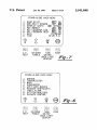
FIG. 5 is an illustration of the main menu of the hand held
directional arrow keys 27 used to parse through character
unit;
strings and step through logic sequences, two enter keys 28
FIG. 6 is an illustration of the hand held unit screen when
to indicate a command is to be entered, ten alphanumeric
selecting a vehicle system for monitoring;
keys 29 for entering letters, numbers and characters, and
eight special function keys 30 used for responding to queries
and the like. The key pad is a membrane key pad in this
FIG. 7 is an illustration of the hand held unit screen when
setting user options;
FIG. 8 is an illustration of the main master station menu
screen;
FIG. 9 is a logic tree showing various features available;
FIG. 10 is a sample diagnostic instruction screen from the
master station;
FIG. 11 is an illustration of a sample display screen from
the master station showing technical information used dur
embodiment because of the harsh environment in which the
20
tionally.
FIG. 12 is an illustration of the master station screen when 25
displaying logged data;
display when dynamically displaying parameters on the
30
logging functions;
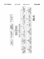
FIG. 15 is a logic tree showing how templates are stored
described in greater detail later. Along the top of the hand
held unit 10, there are connection points 32-38 for electrical
probes, an RS-232 connection 40 for communicating with
other computers and computer peripherals, a vehicle inter
face connection 42 and a GPIB master station interface
connection 44. On the back of the hand held unit, a remov
and retrieved;
FIG. 16 is an illustration of the master station screen as a
At the base of the hand held tool 10, an expansion slot 31,
approximately 2 inches long and 1%: inch wide, is adapted to
receive conventional PCMCIA card memory expansion
boards. The memory expansion cartridges are useful when
using the hand held unit as a data logger, which will be
FIG. 13 is an detailed illustration of the textual data
custom template is being built;
and moisture. Moreover, utilizing a membrane key pad helps
reduce the likelihood that keystrokes are entered uninten
ing diagnostics;
master station;
FIG. 14 is logic tree showing the data recording and
hand held tool operates. By utilizing a membrane, the actual
key contact points are protected from contamination by dirt
35
FIG. 17 an illustration of the service update screen; and
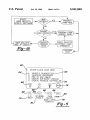
FIG. 18 is a function diagram illustrating the different
ways the hand held unit can be updated.
able cover 46 protects a peripheral expansion port 48. As
will be described in greater detail later, the peripheral
expansion port accepts an expansion module which allows
the hand held tool to be compatible with many other devices,
such as a computer disk drive, a wider variety of vehicle
controllers and other types of measurement tools.
DESCRIPTION OF THE PRESENTLY
PREFERRED EMBODIMENT
The vehicle interface capabilities of the hand held unit
will now be described in greater detail. The vehicle interface
connector 42 is a thirty-six way connector. The hand held
As can be seen in FIG. 1, the system of the presently
unit 10 is interfaced to the vehicle 12 via the vehicle
preferred embodiment includes the hand held unit 10 which
connects to the car 12 and the master station 14 via cables 45 interface cable 16. In this embodiment, the vehicle interface
44 is adapted to work with a variety of interface cables.
16, 18. The hand held unit 10 has specialized hardware and
Speci?cally, six different types of cables are currently sup
software on board for communicating with the various
ported. All of these cables, while utilizing the same thirty-six
controllers on the car. As will be described in greater detail,
way interface, support different communication protocols.
the hand held unit 10 is capable of operating as a scan tool,
For example, an ISO 9141/CARB cable is an asynchronous
volt-ohm meter, and data logging unit by itself without
full duplex serial communication link con?gurable to a
requiring support from the master station. When the master
variety of baud rates, such as 976, 7812.5, 62.5K, and 10.4K
station 14 is connected 18 to the hand held unit 10, the hand
held unit can serve as a smart interface between the master
baud rates, with signal levels varying between an idle
station 14 and the various controllers on the car 12. The
condition of twelve volts and zero volts. Similarly, an SCI-I
internal memory of the hand held unit. The master station
cable is an asynchronous duplex serial communication link
con?gurable to baud rates such as 976, 7812.5, and 62.5K
baud, with the signal levels varying from an idle of zero
volts to ?ve volts. Both the SCI-I and ISO 9141/CARB
further provides interactive data charting capabilities. The
communication links utilize the standard ten bit non return
master station 14 also serves as a paperless service manual,
to zero (NRZ) data format, with one start bit, eight data bits
and one stop bit. Yet another cable communicates using a
master station itself is capable of downloading alternative
55
diagnostic routines to the hand held unit 10 as needed, while
also providing the ability to update and/or recon?gure the
providing detailed pictorial and textural service information.
contention-based, class B multiplexed bus, transferring data
These and other features of the hand held unit 10 and the
master station 14 will be described now in greater detail.
Hand Held Unit
65
at 7812.5 baud via a voltage diiferential generated across the
bus which is biased to 2.5 volts.
Because the same connector interface 42 is used to
As can be seen better in FIGS. 2 and 3, the hand held unit
support all of these various communication protocols, the
10 is approximately 14 inches long, 6 inches wide, 21/2
hand held tool 10 must be able to recognize which cable is
5,541,840
5
6
connected at the interface 42 and adapt its communication
performs diagnostic routines by querying the vehicle con
protocol accordingly. In this embodiment, this is accom
plished by ensuring each of the unique cables has a unique
resistance associated therewith. This unique resistance is
measured and recognized by the hand held unit 10 so that it
may identify the cable to which it is connected and adjust its
trollers via the vehicle interface 42. In the talker mode, the
hand held tool 10 communicates with the master station 14
by transmitting information to the master station. Similarly,
in the listener mode, the hand held tool receives information
from the master station via the interface 44. In this embodi
communication protocol accordingly. Speci?cally, in this
ment, there is no means for the master station to commu
embodiment, two pins of the connector provide the resis
tance signal feed. The resistance signal feed is interfaced to
the control logic circuitry so that the resistance may be
measured and compared to predetermined values corre
sponding to the unique resistances for the various cables. In
this embodiment, the resistance values of the various cables
have been established such that, given measurement toler
nicate directly with the vehicle. Rather, the master station
downloads information to the hand held tool for running
specialized diagnostic procedures, and receives monitored
vehicle perimeter information from the hand held tool via
the communication link.
ances, there is no chance of overlap between the resistance 15
values, which may otherwise cause an erroneous cable
Scan Tool Mode
identi?cation. Speci?cally, a cable for communicating with
the engine controller has a nominal resistance of 3,010
ohms, a cable for communicating with the body controller
has a nominal resistance of 14,000 ohms, and the 11962
of functioning as a diagnostic scan tool. When in scan tool
As was discussed earlier, the hand held unit 10 is capable
20
mode, the hand held unit communicates with the vehicle 12
via the communication cable 16. Depending upon the type
of vehicle being diagnosed and the particular controller
within the vehicle being queried, one of the six available
cable has a nominal resistance of 44200 ohms. Once the
hand held tool 10 determines which vehicle interface cable
16 is connected to it, the hand held tool 10 adapts its
cables, as discussed earlier, will be selected. For the pur~
communication protocol to match the protocol of the cable.
posed of this discussion, it will be assumed that the ISO
This feature allows the hand held tool to be used with a wide
25 9141/CARB cable has been selected because information
variety of vehicles and vehicle controller systems, such as
from a standard engine controller is desired. One end of the
engine, transmission, anti-lock brake and body controllers.
communication cable 16 is connected to the hand held unit
The actual architecture of the hand held unit’s controller
10, while the other end of the cable is connected to the
can be found in FIG. 4. As shown here, there are two
vehicle 12 at the service connector interface, usually located
microcomputers on board, an ST9 50 and an MC68332 (not 30 underneath the hood or the dashboard. The hand held unit 10
shown). The ST9 microcomputer, commercially available
measures the resistance of the cable 16 and determines that
from S. G. Thomson of Texas, is the communications
it is the ISO 9141/CARB cable, and con?gures its commu
coprocessor while the MC68332 rnicrocontroller, available
from Motorola of Illinois, performs the diagnostic and data
gathering features. The ST9 controller has A-D converters
52 for measuring and scaling information from the vehicle
interface connector, and has addressing and data control
nication protocol accordingly. The hand held unit 10, once
35
tool via the key pad.
As shown in FIG. 5, upon powering up the hand held unit
bu?ers 54—60 for communicating with the MC68332 con
troller. Likewise, the MC68332 has interface buffers and
A-D converters. Here, both regular speed and high speed
40
A-D converters are used to ensure the data gathering process
is rapid and accurate. On board, the hand held unit has 4.5
megabytes of memory. One 250K block of memory is the
boot ROM, which can be reprogrammed, or “?ashed”, to
alter the operation of the hand held unit. The boot memory
contains the operating system and device drivers used by the
hand held unit. Another 250K block of memory is pseudo
static memory with a ninety-six hour storage life. This
storing customized data gathering templates. Another 1 Mb
block of memory is also ?ashable, and stores the diagnostic
procedure information. This memory can be re?ashed via
10, the technician is presented with a menu display 60
providing a variety of options and function keys. In this
initial screen con?guration, the technician can select any
menu item 62 by pressing the corresponding number 64 or
can invoke a function such as “help” 66, “screen toggle” 68,
45
“illuminate back light display” 76 and “stop” 72 by pressing
the function F1 through F4 keys 74-80, respectively. It
- should be noted that providing the generic key face labels
“F1” through “F4” 82-88 While providing the function
memory is used for storing specialized diagnostic routines
that have been downloaded to the hand held unit, and for
connected into the vehicle communication bus via the inter
face, sends commands to the engine controller and receives
information back. These corrunands are executed by the
service technician by entering information in the hand held
describer in the form of an icon located above the key allows
50
the key pad to be freely con?gurable through software. For
example, since no action is being undertaken by the hand
held unit when the initial menu is presented, the F4 key need
not be assigned the function of “stop”. Rather, at that stage,
the master station link 18 from the master station 14 or can
the key may be de-assigned, in which case no icon 66~72
be re?ashed using a memory expansion card in one of the 55 would appear over it and no action would be taken in the
expansion slots 31, 48 or via the RS232 serial link 40.
Another 1 Mb block of memory is pseudo static memory
with an eight hour life. This memory, like the ninety six hour
life memory, is used to store information such as specialized
diagnostic routines. The ?nal 2 Mb block of memory is
RAM.
The master station connection port 44 supports GPIB
communication protocol between the hand held tool 10 and
the master station 14. When connected to the master station,
event of that key being stroked, or the key may be reas
signed, in which case a new action and associated icon can
be designated. One of ordinary skill in the art can appreciate
that the ability to assign, reassign and de-assign activities to
the function keys allows the scan tool to be readily con?g
ured for use with a variety of vehicles and vehicle controllers
without requiring physical modi?cation of the unit. More
over, the icons can serve a dual function of being both a key
identi?er and an activity indicator. In this embodiment, the
the hand held tool can operate as the controller, talker or 65 “stop” key serves not only to identify that the F4 key will
listener. When in the controller mode of operation, the hand
invoke the stop function, but also serves as an operation
held tool controls the operation of the master station and
in-progress indicator by blinking whenever an operation is
5,541,840
7
8
running. If the technician invokes the stop function, the icon
stops blinking to indicate the operation has been stopped.
tance reading on the screen. Thus, rather than requiring the
technician to grab a separate ohm meter and perform the
reading and input the measurement into the hand held unit,
integrating the DMM mode into the scan tool mode allows
Action taken based upon the actuation of a function key
26 is immediate; that is, there is no need to press the enter
key 28 to execute a function key. In contrast, while the
alphanumeric keys 29 are used to enter characters, the
characters are not actually acted upon until the enter key 28
is pressed. For example, to select item number one, “vehicle
diagnostics” 62, the user can depress the numeral one on the
key pad to move the highlight curser bar to the ?rst item.
Similarly, the user could use the directional arrow keys 27
to scroll the highlight bar to item number one. Once the
the measured reading to serve as the technician’s response to
the scan tool’s query.
Additionally, the technician can invoke DMM mode by
simply pressing the DMM key on the key pad. Invoking
DMM mode simply suspends whatever operation the scan
tool is currently engaged in for being resumed at a later time.
Speci?cally, a split window is opened on the display screen:
the top half of the window shows the DMM mode, while the
bottom half of the screen shows the suspended operation.
The technician can toggle between DMM mode and the
highlight bar is highlighting, or pointing to, the ?rst item, the
user depresses the enter key to indicate that the ?rst item is
the desired item to be acted upon. In this way, accidental key
suspended operation by using the F2 “toggle up/down” key.
strokes do not result in unintended activity. In the event of
When the technician toggles down to the operation window,
an accidental key stroke, the key stroke can simply be
the operation is resumed and the DMM mode is suspended.
overridden by later key strokes or the character typed over
To completely exit from DMM mode, the technician simply
by backing the curser over the character and typing a new
depresses the DMM key again. Thus, the technician can be
20 performing a diagnostic procedure on one vehicle and can
character.
interrupt that procedure to perform an electrical reading on
When in scan tool mode, the user can step the hand held
a separate vehicle without requiring the technician to ter
unit 10 to accomplish diiferent procedures. As shown in FIG.
minate the diagnostic procedure on the ?rst vehicle. This
5, once the user selects the vehicle diagnosis option, the next
feature further enhances the technician’ s ability to operate in
screen the user is presented with is the system selection
screen, shown in FIG. 6. In this screen, the user can decide 25 an ef?cient manner.
which controller is to be queried. Depending upon the
system selected, the user is presented with a variety of
options for querying the controller as to stored diagnostic
example, to measure the voltage drop across an element
codes and monitoring operational parameters. For example,
using conventional means, the technician would be required
Moreover, by providing two sets of probes, the technician
can perform voltage differential tests quickly and easily. For
most engine controller store codes in the event that an 30 to use two separate meters and perform two separate read
operational problem is detected. For the purposes of this
discussion, the error code stored by the engine controller
ings, subtracting one reading from the other to obtain the
difference. By using the hand held tool in the DVOM mode,
will be assumed to be an error code associated with an O2
the technician can simply attach each set of probes across the
sensor reading below the required threshold. Using the hand
held unit, the technician can send commands to the engine
controller to have the engine controller relay its fault code
information to the hand held unit for display. In this instance,
element in question and the hand held unit displays the
35
probes can be operated independently of the other. That is,
such a command would result in the display providing a
one set of probes can be used to measure current draw while
reference such as “02 sensor threshold low”. Based upon the
the other set of probes can be used to measure voltage drop.
fault codes read, the technician can then decide how he
would like to isolate the problem. If desired, he can connect
the hand held unit to the master station to progress through
a diagnostic routine, wherein the technician is stepped
through a series of actions which help the technician identify
and isolate the cause of the problem. In this instance, the fact
that the O2 sensor reading is abnormally low does not
Again, the technician’ s e?iciency is greatly improved by this
feature. Rather than requiring the technician to use separate
meters to perform different types of readings, or requiring
45
the technician to perform these different readings sequen
tially, the technician can simply attach the probes to the
items in question and perform these diiferent types of
readings simultaneously.
necessarily mean that the O2 sensor is bad. Therefore, the
A further feature of the DMM mode is that single probe
measurements are possible. This feature is especially impor
diagnostic actions prescribed in the diagnostic steps would
walk the technician through the fault diagnosis procedure to
aid him in isolating the problem. The manner in which the
hand held unit and the master station cooperate when
voltages on the screen.
A further feature of the DMM mode is that each set of
50
mnning diagnostics will be described in greater detail later.
tant when attempting to measure electrical characteristics of
devices in hard to reach locations. Because the hand held
unit can be connected into the vehicle communication bus
Another important feature of the hand held unit is its
via the communication link, the hand held unit is provided
with system and chassis ground via the communication link,
obviating the need to provide a separate measurement
ground via the test probe. Therefore, using only one lead of
ability to operate as a stand alone digital multi meter
the test probe, voltage and current measurements can be
(DMM). In this embodiment, the hand held unit is provided
obtained, using the signal or chassis ground provided via the
with two sets of probe inputs 32—38 to allow measurements
communication link as the measurement ground.
Digital Multi Meter Mode
55
at two test points. Operation as a DMM can be invoked two 60
different ways. First, the technician may be requested to
Controller Update Mode
perform an electrical reading as part of one of the diagnostic
steps. For example, using the O2 sensor hypothetical, one of
The hand held unit is also capable of downloading infor
the diagnostic steps may require the technician to measure
mation to the vehicle controllers for the purpose of updating
the resistance of the O2 sensor. By placing the probes at the 65 these controllers. For example, most controllers utilize a
appropriate point on the O2 sensor, the hand held unit will
combination of ROM and RAM. The ROM contains the
measure the resistance of the sensor and display that resis
control algorithm and calibration parameters, while the
5,541,840
9
10
RAM contains operational parameters. When controllers
date once again exhibiting a faulty O2 sensor reading, the
stored service history information can be used during a
diagnosis procedure to direct the technician to check the
were ?rst being used on automobiles, the ROM was hard
coded, that is, the ROM was ?xed and unchangeable.
Likewise, RAM was volatile and any information stored in
RAM would be lost if the controller power supply was
interrupted. Today, automotive controllers rely upon a com
bination of hard coded and erasable ROM in addition to
RAM. The erasable ROM usually contains information such
as calibration parameters. Frequently, after a vehicle has
connection to see if the connector simply needs to be
replaced. As such, one of ordinary skill in the art can
appreciate how the storing of service history information in
the vehicle controller’s memory would be valuable, and that
the type of information stored can be customized to suit the
speci?c needs of the situation.
been introduced into production, knowledge learned after
use of the vehicle by customers in the ?eld will necessitate
Customized Templates
a change in calibration parameters. Rather than requiring the
From the foregoing discussion, it can be appreciated that
entire controller to be removed and replaced or the memory
chips to be removed and replaced, storing calibration param
eters in erasable ROM allows the calibration parameters to
15
be rewritten. Here, the hand held unit has the capability to
To accomplish this, the hand held unit has, stored in its own
internal memory, the new information to be downloaded to
are burned out or doors are opened. Thus, it is possible for
the hand held tool to gather, from a variety of sources,
the vehicle controller. The technician enters the ?ash pro
gramming mode by selecting the appropriate menu item
information necessary to diagnose problems. Moreover,
from the display screen. Once this mode is selected, the hand
held unit sends a control message to the controller to inquire
as to the version and model number of the controller’s
there may be instances when the service technician desires
to monitor information from these various sources simulta
25
controller, the hand held unit determines whether or not the
vehicle controller’s memory needs to be updated. If the
memory does need to be updated, the technician is presented
with a screen indicating so and asking the technician
whether or not he wishes to proceed. Assuming the techni
cian has indicated his desire to proceed by pressing the yes
neously during service and maintenance routines. Therefore,
the hand held unit has been provided with the capability for
the technician to develop customized reading templates for
gathering such diverse information quickly and e?iciently.
To develop a customized template, the technician simply
selects the menu item for using and storing templates. By
selecting this item, the hand held unit is placed in a pro
gramming mode of sorts.
The technician can retrieve prede?ned templates from
key, the hand held unit sends the commands to the vehicle
controller necessary to recon?gure the programmable ROM
to re?ect the new calibration values. The process of sending
the appropriate commands and calibration data to a vehicle
controller and verifying that the information has been cor
rectly received and stored is well within the grasp of one of
ordinary skill in the art, and therefore will not be described
provide information regarding fuel-air ratio, the transmis
sion controller can provide transmission oil temperature, the
anti-lock brake controller can provide wheel speeds and the
body controller can provide information on whether lamps
write, or “?ash”, erasable memory on the vehicle controllers.
memory. Upon receiving the response from the vehicle
the hand held unit can monitor hundreds of di?°erent param
eters on the vehicle. For example, the engine controller can
memory and can store and retrieve customized templates as
35
well. To retrieve a predetermined template, the technician
simply selects that template from the selection list. For
example, such a predetermined template may provide infor
in detail herein. Once the commanding, writing and veri?
cation process has been completed, the hand held unit
mation as to whether or not the brake pedal is depressed and
whether or not the brake lamps are illuminated for the
purpose of diagnosing wiring or lamp failures. While such a
displays to the technician whether or not the vehicle con
predetermined template is usually retrieved automatically
troller update procedure has been successful.
during the process of performing a diagnostic routine in the
Service History Recording Mode
45
The hand held unit is also capable of recording service
history information on the vehicle controllers. Similar to the
process of updating calibration information, the hand held
unit can send commands to the vehicle controller to store
scan tool mode, the technician can selectively retrieve
predetermined templates for use outside of the scan tool
mode.
It can also be appreciated that the technician may find a
need to de?ne his own customized templates. To do this, the
technician enters the customization mode and simply selects
from lists those parameters he wishes to display in this
information regarding service procedures. For example,
customized template. After selecting the items and building
when in the scan tool mode, the technician is reading fault
code information from the vehicle controller in an attempt to
diagnose and isolate the cause of the fault condition. Once
the technician has successfully isolated and remedied the
the template, the technician can store this customized tem
problem, the service history recording mode of the hand held
55
unit allows the technician to erase the fault code from the
vehicle controller’s memory and store codes indicating what
procedures were performed and when. Such information
proves very useful during later diagnostic procedures when
attempting to isolate new fault conditions, because actions
taken by service personnel during previous service visits
often a?ect the manner in which new problems are diag
nosed. For example, through the service history recording
mode, the technician could indicate that, using the hypo
thetical O2 sensor situation, the low 02 sensor reading 65
problem was cured by reseating the O2 sensor connector. In
the event the vehicle is brought in for service at some later
plate in the memory of the hand held unit by selecting the
store option and entering an appropriate template identi?er
string. For example, the technician may simply want to store
the template by identifying it as “CUSTOM 1”, or may wish
to identify the template by his name, the date, or other such
unique identi?ers. To enter characters for the template
identi?er string, the technician simply presses the shift key
while simultaneously pressing one of the alphanumeric keys
to access letters rather than numerals. For example, to enter
the ?rst character of “CUSTOM 1", “C”, the technician
would hold the shift key down while depressing the llABC
key three times: the ?rst time he pressed the key the letter A
would appear, the second time the letter B would appear, and
the third time the letter C would appear. In the event that the
technician presses the key too many times, the character
sequence simply restarts. Therefore, upon the forth time, the