1
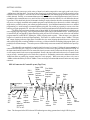
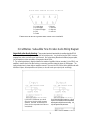
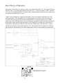
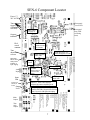
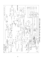
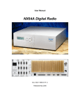
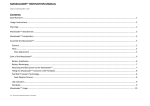
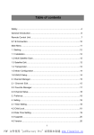
SubAudible
Tone Encoder
Model SEN-6
CircuitWerkes
Technical Manual
CircuitWerkes
3716 SW 3rd Place · Gainesville, FL 32607
(352) 335-6555 · Fax (352) 380-0230
http://ww.circuitwerkes.com
e-mail: [email protected]
c 1995-1999 CircuitWerkes All Rights Reserved. All information contained within is proprietary.
No part of this manual may be reproduced or copied without the express written consent of CircuitWerkes.
The CircuitWerkes Subaudible Tone Encoder
Description
The CircuitWerkes Subaudible Tone Encoder is a single channel tone generator capable of
encoding 25Hz, 35Hz and 25/35Hz combination tones for signalling and remote control of automated
systems over satellite, RPU and other media capable of passing subaudible signals. The unit has individual
inputs for 25Hz, 35Hz and combination tone generation. In addition to standard 25 and 35Hz tones, the
SEN-6 can, with external filtering, generate 50, 75 and combination 50/75Hz tones. Outputs are provided
for low tone, high tone and shifted (50/75) tone mode. An LED indicator on the front of the box illuminates
any time a tone is being sent. The SEN-6 is designed to be the last device in an audio chain and all
program audio should be passed through the SEN-6. Internal notch filters eliminate subaudible content
from the program material. The audio input can accept balanced or unbalanced audio at input levels of
-20dBm to +8dBm. The output is balanced, transformerless and can drive a 600 ohm load. Subaudible
program content is typically attenuated by 40dB at the audio output and it is short-circuit protected.
Installation & Setup
CONNECTIONS:
Connections to the subaudible tone encoder are fairly straight forward. Your audio passes through
the encoder via the Audio In and Main Out jacks. When the input is unbalanced, the (+) input lead should
be tied to ground and the input driven via the (-) input. Power inputs are brought out to both barrier strips and
a coaxial power connector. Both of the power connectors are in parallel with each other, so only one power
source at a time can be connected to the SEN-6. Power is provided by the included "wall-wart." Connection
can be made to either port, depending on which type of adapter was supplied with your encoder. The
SEN-6, as is the case with most CircuitWerkes products, uses an internal bridge and Voltage regulators so, it
can be powered with any supply of 17-24 Volts AC or DC capable of delivering 150mA.
All control inputs are opto-isolated and require simple ground closures to operate. Indicator outputs
are also opto-isolated and and operate whenever their specific tone is generated. An additional barrier strip
position is for the encoder enable function. This input is active if Jumer J7 is removed. When J7 is removed
and there is nothing connected between the enable input and ground, no tones will be produced. This feature
lets you prevent accidental closures, except at pre-determined windows. If J7 is removed, the SEN-6 must
have a connection between the enable input and ground for it to output tones. J7 simply parallels the external
input connector. If J7 is on (the default) the SEN-6 will operate whenever its input is activated. Finally, in
addition to the screw terminals, a D-9 connector duplicates the control and signal functions (See page 5).
Indicator outputs for for low tone, high tone and shifted (50/75) tones are ground sinking
optocoupler outputs. These outputs are rated at 24V and 100mA. If higher Voltages or more current is to
be switched, an external slave relay is highly recommended.
Audio input gain, output level and tone insertion level are controlled by front panel pots. An LED
indicator is provided to show you when audio is present and when both input and output clipping are
happening.
Jumper J2 removes subaudible tones from the program path when off. A second output jack
labelled "Test Mode Out" contains only raw subaudible tones, minus program material. By removing J2
and monitoring the "Test Mode Out" connector, you can test and adjust the level of your tone generator
without getting tones on the air or removing the encoder from your air chain.
J5 selects whether the Input LED detects presence or input clipping.
Tone duration is user selectable via J6 from .75sec. to 2 secs. via the 5 position jumper. When all
positions are un-jumpered, the encoder produces a 10 second tone for testing.
3
SETTING LEVELS:
The SEN-6 can accept a wide variety of input levels and its output driver can supply peak levels of up to
+16dBm into a 600 Ohm load. Decisions on how to set levels are based on how you will use the encoder, but one
cardinal rule always applies: Tones must be at least 10dB hotter than surrounding program material in order to be
reliably detected. Actually, we recommend that tones not be transmitted over other program material at all. However,
you may be able to transmit tones over music buffers as long as the music has faded by 10 to 20 dB before the tone
is generated. This should only be tried if automatic ducking is employed and/or the tones are automated so that they
only occur over tightly controlled and repeatable program events that have been shown to be reliable. Although it
might also be possible to reduce your normal program material by 10 to 20dB and transmit the tones over unfaded
programming, we would strongly recommend against trying that. You would pay a penalty in excess noise from
reducing your peak program levels. Also, there is a lot of room for misadjustment of individual decoders downstream.
The SEN-6 has a maximum dynamic range of about 90dB. By selecting the highest input level that does not
cause clipping of the input stage, you will get the maximum signal to noise ratio from the SEN-6. Audio input gain
is controlled by R7 and should be adjusted until the audio presence LED is flashing most of the time with normal
program material, but WITHOUT lighting the LED in clipping mode on peaks. After the input is set, adjust the
output level control for the desired output amplitude. This control is variable from 0 to about +16dBm. The input
and output clipping indicators light about 0 to10dB below the actual clipping threshold, however, unprocessed
audio usually has peaks exceeding 10dB above reference, so if these indicators are flashing with program peaks, you
probably have distorted output. The audio presence LED initially turns on at around 20-25dB below the input clip
level.
The subaudible tone amplitude is controlled only by the tone level control. Neither the input or output level
controls affect the tone gain. One way to set the tone level is: insert a tone or program audio at normal levels & set
the input control until the audio LED is on most of the time in presence mode, but not on at all in the clip mode. Next,
set the output control for the correct output amplitude. Remove the input audio and set the tone level control for the
correct (usually = nominal pgm level or a little more) output level. Remember, tones must be undistorted and at least
10dB hotter than any underlying program material to work properly. While tones may not have to be sent at
+10dBm, neither should they be sent at -20dBm. Tones can always be monitored & measured at the tone only output
connector.
SEN-6 Connector & Controls Layout (Top View)
Db-9
conrol
connector
Low,
Power Tone
high &
17- triggers
24V
Enable shifted
output
AC/
input.
DC
Must be indicators
grounded
if J7 is off..
Input LED
Mode.
Selects audio
present
indicator or
input
clipping
Test Mode
Jumper
(removes tone
from main
Input
output).
LED
Tone
Tone
duration Level
selector Set
Audio
Input
connector
Output
clip
LED
Output
Level
Set
Input
Gain
Set
Tone
Main
Only
Audio
connector
Output
connector
Note: The front panel of the SEN-6 has an LED indicating tones being generated and a single LED for power.
4
1 = Lo tone trigger
= Hi tone
Disable Input.2 Remove
J4 andtrigger
short to enable
relays.
3 = Combo tone trigger
4 = Shift
5 = Enable
6 =Ground
7 = Shift sink
8 = High sink
9 = Low sink
Connections on the Db-9 parallel those on the screw terminals.
CircuitWerkes Subaudible Tone Encoder Audio Wiring Diagram
Important note about phasing:
There are two important characteristics to consider about the SEN-6:
1. The notch filters exhibit significant phase shift at low frequencies. You should not use the SEN-6 on stereo
program lines unless you have one on each channel. Also, when mixing filtered and unfiltered program paths,
you will experience some cancellation of frequencies below 150Hz.
2. The actual output phase is directly related to the number of amplifiers that are cascaded. In the SEN-6, one
amplifier is used for each of the filter sections, so removing one filter rotates the phase by 180 degrees. The
input and output are in phase with one amplifier removed. If you use the SEN-6 in the factory default mode with
both filters in place, the output will be out of phase, so be sure to wire your output jacks accordingly.
Do not connect either driven output (+) or (-) directly
to ground! These outputs are short circuit protected,
but prolonged shorting will cause overheating and
may also degrade audio performance.
If your audio is unbalanced, you should
drive ring and tie tip to sleave for proper
operation. Note that the audio will be in
phase with the output when both filters are
used (default).
5
Short Theory of Operation
Input audio is buffered by U1c and sent to the low frequency notch filter, U1d. The output of the low
frequency filter goes to the high frequency notch filter, U1a. A series of jumpers, J3 & J4 allow the
user to use one or both notch filters. Program audio, with subaudible content removed, is then fed to
the output mixer/buffer/amp, U2c & d.
Control inputs and indicator outputs are generated by the microcontroller and buffered by TIL199b optocouplers. The subaudible tones are first generated as raw PWM in the microcontroller.
From there tones are levelled and pre-filtered then passed to a switched capacitor low pass filter
which removes the PWM distortion. The tones then go to a daughter board which mutes the first few
milliseconds of tone and then ramps the audio up to full amplitude, avoiding pops when the tone is
first produced. By ramping up the tone audio, detection is improved on some decoders. Output
from the mute circuit is sent to buffer amplifier, U1b. The output of U1b is sent directly to the tone
only output jack and through J2 to the main output buffer where it is mixed with the program audio.
U2c/d
U2a/b
SEN-6 Mute PCB Layout
6
SEN-6 Componant Locator
Power 1724V AC/DC
Tone
triggers
(Grounding
activates)
Front panel
power LED
Front panel
Busy LED
(on during
tones)
Enable input
(see page 3).
Output
indicators
Db-9
conrol
connector
J7 Remove to
disable/activate
ext. Disable
Tone
duration
selector
Input LED
Mode. Selects
audio present
indicator or
input clipping
Audio
Input
J9 HF filter gain. Use
when setting filter to 63Hz.
High frequency
notch tune
Tone
Level
Filter selectors
Test Mode
Jumper (removes
tone from main
output).
Low frequency
notch tune
Input
Gain
10dB input pad.
(Normally not
needed)
Output
Level
Input LED. Shows either clipping or
nominal audio presence depending on the
position of J5.
Output clipping LED. When flashing indicates
audio is within 3dB of clip point (into 600 Ohm
load) Clip point is 3dB higher into bridging
load.
Main
Output
Tone
Only
Output
7
SEN-6 Subaudible Tone Encoder Schematic
8
Alignment
Levels.
Audio levels can be adjusted with the front panel audio pots (Input and Output). Start with the Input
levels and feed the unit with normal program audio. Adjust the input until the input audio presence LED
flashes with about 50-70% duty cycle with the incoming audio; it can flash more if the audio is densely
processed. Output audio should be adjusted for desirable levels into your program path. If the red "Out Clip"
LED is illuminating at all, you are getting within 4dB of clipping on peaks. If this same LED is not lighting,
but your audio out is distorted, you are probably driving the input too hot. Check for a flashing "Input Clip"
LED and set the input gain control for the maximum gain that does NOT cause the input clip LED to flash.
Filters.
All adjustments to the encoder assume 25 and 35 Hz signal encoding. The process for setting 50 and 75 Hz
encoding is identical, except, of course for the frequencies and one jumper. When setting up for 50/75Hz operation, it
is assumed that you will still want to encode 25 & 35 Hz, so compromise frequencies of 29.5Hz and 62.5 Hz have been
selected to give roughly equal attenuation at 25, 35, 50 & 75Hz. Note, however that the maximum attenuation at any
one frequency achievable using only the two internal notch filters is about 17dB, which may not be acceptable if your
program material contains significant amounts of music or other subaudible content. If you are planning to use the 50/
75Hz options, we suggest leaving the two low frequency filters set and use an external EQ before the SEN-6 to roll off
audio below 100Hz. The filter sections are tuned at the factory with standard reference tones and should not need
further adjustment by the user. However, if the need unexpectedly arises to tune these circuit sections you will need a
scope or analog audio level meter that has good display characteristics at low audio frequencies, a signal generator or
known accurate 25Hz and 35Hz signal source, and an accurate frequency counter if your signal source is a continuously
adjustable device (most are). The frequency counter can be left hung across the signal source for fine tuning the
frequency of the signals being fed during the alignment process. The audio level of the tone source should be between
-10 and +8 dBm. If the signal is unbalanced, be sure to tie ring and sleeve on the input connector to the unbalanced
source's shield.
To Tune the filter sections set the generator or signal source for the operating frequency of the filter being tuned
and adjust the associated multiturn pot for minimum audio (the null point) at the main output. A properly tuned filter
will attenuate the notch frequency by 40dB or more. R16 adjusts the low frequency and R26 adjusts the upper
frequency. If R26 is adjusted for 63 or 75 Hz, J9 should be removed to match the gain through that stage.
J3 and J4 set which filters will be on-line. You can select low only, high only or both. If you are only using one tone,
greater low frequency response and less low frequency phase shift can be obtained by using only the filter for the
desired frequency. However, removing one filter from the circuit inverts the output phase, so care should be taken to
avoid out of phase mixing downstream.
J3 & J4 - Filter select
Key:
J3 1&2 & J4 2&3 = both filters in
J4 1&2 = low filter only
J3 2&3 & J4 2&3 = high filter only
High frequency
filter gain set.
High Frequency
notch filter adjust
Low Frequency
notch filter adjust
9
REPAIR OR SERVICE INFORMATION
In the event of the need for service or repair, call CircuitWerkes at (352) 335-6555 for a
Return Merchandise Authorization number (RMA). Then carefully package the unit along
with a note of the problem and send it to the address below. Clearly indicate the RMA
number on the outside of the box. We cannot accept returns without an RMA. Be sure to
include your address (not a PO box), telephone number and best time to call.
CircuitWerkes
ATTN: CUSTOMER SERVICE DEPT.
3716 SW 3rd Place
GAINESVILLE, FL 32607
CircuitWerkes Limited Warranty
This product is warranted against defects for two years from date of
purchase from CircuitWerkes and CircuitWerkes authorized distributors.
Within this period, we will repair it without charge for parts and labor.
Proof of purchase-date required. Warranty does not cover
transportation costs, or a product subjected to misuse, accidental
damage, alteration (except as authorized by CircuitWerkes),
improper installation, or consequential damages.
Except as provided herein, CircuitWerkes makes no warranties, express
or implied, including warranties of merchantability and fitness for a
particular purpose. Some states do not permit limitation or exclusion
of implied warranties; therefore, the aforesaid limitation(s) or
exclusion(s) may not apply to the purchaser. This warranty gives you
specific legal rights and you may also have other rights which vary from
state to state.
Note: Although every effort is made to make our technical materials complete and accurate,
manuals are frequently updated in order to improve them. All specifcations and information
contained herein is subject to change without notice. The latest version of this manual is available
online at the CircuitWerkes internet web site. The address is: http://www.circuitwerkes.com/
E-mail may be sent to [email protected].
10