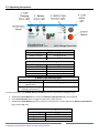
1
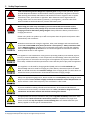
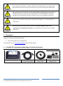
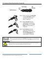
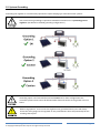
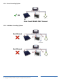
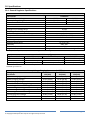
EcoOnline™ 12V/24V Solar Regulator For the EcoOnline Solar Kits using the 1R/20Amp/24V Solar Charge Controller Installation Manual & User Manual - Revised 31/01/2015 Optex Solar Pty. Ltd. www.EcoOnline.com.au email: [email protected] © Copyright 2012 Optex Solar Pty Ltd. All rights strictly reserved. This publication is protected by copyright law and unless otherwise specified is for your personal and non-commercial use only. No part of this publication may be reproduced or distributed by any process, electronic or otherwise, without the specific written permission of Optex Solar Pty Ltd. Trademarks appearing in this manual are the sole property of Optex Solar Pty Ltd or their respective owners. Nothing in this publication shall be construed as granting any express or implied license to use any intellectual property of Optex Solar Pty Ltd otherwise than for personal and non-commercial use only. Optex Solar Pty Ltd must not, to the full extent permitted by law, be held liable for any claim, cost (including legal costs), damage, expense, loss (including fines, penalties, set-offs and consequential loss) or liability arising from the use (or misuse) of any product described in this publication, unless expressly provided otherwise in this publication. Information as well as any products described in this publication are subject to change without notice. Eco Online™ Solar Regulator Kit -- Installation and User Manual © Copyright 2012 Optex Solar Pty Ltd. All rights strictly reserved. Page 1 Contents 1 Key Terms .................................................................................................................................................................. 3 2 Safety Requirements ................................................................................................................................................. 4 3 Warranties ................................................................................................................................................................ 5 4 Included Kit Components (depending on the kit purchased) ................................................................................... 5 5 Designing Your Charging System............................................................................................................................... 6 6 Connecting the Load Direct to Battery or Through the Regulator............................................................................ 6 7 Recommend Position of Regulator ........................................................................................................................... 7 8 Fuse and Technical Wiring Diagrams ........................................................................................................................ 8 9 Fuse Assembly ........................................................................................................................................................... 8 10 Solar Panel Wiring ............................................................................................................................................... 10 11 Wiring in Twin Folding Panels ............................................................................................................................. 13 12 Mounting the Solar Panel(s) ............................................................................................................................... 14 13 Mounting the Charging Regulator ...................................................................................................................... 15 14 Regulator Connections ........................................................................................................................................ 15 15 Wiring and Connection Order ............................................................................................................................. 16 16 Auto Voltage Selection - 12V or 24V System ...................................................................................................... 16 17 Lap Splice Soldered Connection .......................................................................................................................... 17 18 Connector Dismantling Procedure (if required) ................................................................................................. 18 19 System Grounding ............................................................................................................................................... 19 20 Specifications ...................................................................................................................................................... 21 21 Operating Instructions ........................................................................................................................................ 22 22 System Maintenance........................................................................................................................................... 23 23 Trouble Shooting Guide ...................................................................................................................................... 23 Eco Online™ Solar Regulator Kit -- Installation and User Manual © Copyright 2012 Optex Solar Pty Ltd. All rights strictly reserved. Page 2 1 Key Terms Congratulations on the purchase of your EcoOnline™ Solar Regulator Kit. Please print this manual out for your reference. Please take the time to read the manual before starting any work. Particular attention should be given to text contained in the following key terms. Please note EcoOnline has a strong product safety policy; do not install products without reading safety guidelines in the manual. Please report any product safety issues or near misses to [email protected] no matter how trivial. Indicates a SAFETY issue that is likely to cause injury or death if the user does not follow the instructions. Indicates a SAFETY issue that may cause injury or death if the user does not follow the instructions. Indicates a SAFETY issue that may cause injury or property damage if the user does not follow the instructions Refers to critically important information related to the correct functioning of the system. Refers to useful information for the optimal operation of the system Eco Online™ Solar Regulator Kit -- Installation and User Manual © Copyright 2012 Optex Solar Pty Ltd. All rights strictly reserved. Page 3 2 Safety Requirements Lead acid batteries generate dangerous explosive gases during normal operation; always provide adequate ventilation to the outdoors. Wear eye protection and gloves at all times when working around lead acid batteries. Be mindful of sources of ignition such as sparks from shorts, fuses, open flames or cigarettes. Note: batteries store a large amount of energy. Never short circuit a battery’s positive (+) and negative (-) terminal. Have fresh water available to wash and clean any contact with battery acid. When sizing your solar array and battery you must check that the maximum current produced by the chosen solar panel(s) array can never exceed the maximum allowable charging current for the battery being charged. Always follow the battery manufacturer’s charging instructions. Please note: panels can produce up to 30% more power than the panels rated power under extraordinary solar conditions. EcoOnline recommend de-rating the regulator. Solar panel wattages and connected loads should not exceed: 240W solar power (at STC for a 12V system) or 15Amp continuous load for the 20Amp regulator. If appliances are connected to the battery through the regulator, then the total surge start up current from all connected appliances should not exceed the 20Amp rated current for the regulator. This appliance is not intended for use by persons (including children) with reduced physical, sensory or mental capabilities, or lack of experience and knowledge, unless they have been given supervision or instruction concerning use of the appliance by a person responsible for their safety. Children should be supervised to ensure that they do not play with the appliance. This regulator is to be used for charging Sealed (AGM), Gel or Flooded Lead-Acid type batteries only. Not to be used for charging any other battery chemistries apart from LeadAcid. You should check that the maximum voltage of the charging profile you select does not exceed the battery manufacturers recommended maximum charging voltage. Always use appropriate gauge wires. Never exceed the rated Ampacity (amp rating) of a wire. Keep in mind that wires situated in highly insulated environments cannot dissipate heat and hence will have a much lower Ampacity. This could lead to a fire hazard. If you are unskilled in making safe electrical connections, we recommend all electrical connections be carried out by a certified electrician. Loose, corroded or fatigued electrical connections can become resistive and overheat creating a fire hazard. An appropriate fuse must be installed on the positive regulator to battery connection. Some batteries and/or banks of batteries connected in parallel are capable of very high short circuit currents and may also require a current-limiting fuse. You should check with your battery supplier as to the type of recommend fuse. Eco Online™ Solar Regulator Kit -- Installation and User Manual © Copyright 2012 Optex Solar Pty Ltd. All rights strictly reserved. Page 4 Do not expose this regulator or system components including solder joins to water and/or high humidity and/or corrosive environments such as those involving marine applications. Always disconnect all connections to the regulator before attempting any maintenance or cleaning to reduce risk of electric shock. Note: there are no serviceable parts inside the controller; do not attempt to repair the controller. Incorrect re-assembly can cause fire. Only use 12V “nominal” (36 cell) solar panels with this regulator. Or 72 cell panel(s) for a 24V system. What follows are general installation guidelines, they should NOT be taken to be appropriate for all installation situations, if in doubt please seek advice from a certified electrician. 3 Warranties EcoOnline™ offers the following Warranties 3 year limited Warranty on all Regulators See EcoOnline.com.au Terms and Conditions page for further details. 4 Included Kit Components (depending on the kit purchased) 20Amp Solar Charging Regulator two core 1.0mm2-1.5mm2 5m Solar Wire (10Amp) Eco Online™ Solar Regulator Kit -- Installation and User Manual © Copyright 2012 Optex Solar Pty Ltd. All rights strictly reserved. single core 2.5 -4mm2 Battery Wire 20Amp Fuse holder, 30Amp fuse kit. Page 5 5 Designing Your Charging System Firstly, please visit our online sizing calculators to size your system. They will help you understand important factors involved in sizing a solar charging regulator system. (Do not assume the supplied components are suitable for all situations!) 1. Solar Panel Sizing Calculator (this will help you understand the factors involved in a sizing solar panels) 2. Solar Regulator Calculator (this will help you understand the factors involved sizing a regulator) 3. Solar Wire Sizing Calculator (this will help you understand the factors involved in sizing wire gauges) A charging system must be sized right, for efficiency, reliability and safety. If in doubt please seek advice. 6 Connecting the Load Direct to Battery or Through the Regulator The first choice you have to make is whether you will be connecting your 12V/24V load direct to the battery or through your regulator. Option 1: (Recommended) Advantages * Regulator will protect the battery from low voltage deep discharge Option 2: Advantages * Regulator and regulator to battery wire need only be sized to the maximum power of the solar panels Option 1: Disadvantages * Expensive high gauge wire will be needed if you have a high power load and a long battery to regulator distance * You’ll need to size your regulator to handle the load Option 2: Disadvantages * No deep cycle protection for the battery Eco Online™ Solar Regulator Kit -- Installation and User Manual © Copyright 2012 Optex Solar Pty Ltd. All rights strictly reserved. Page 6 7 Recommend Position of Regulator We recommend the regulator be positioned near the battery. The regulator should not be mounted in the same compartment as flammable objects or items that can leak flammable gas or vapour, such as lead-acid batteries, solvent, gas or oil sources. If installing in the same compartment as lead acid batteries there should be sufficient ventilation. Do not allow the regulator to be exposed to rain or moisture. Please note: when choosing a location for the regulator it is preferable that the regulator and battery compartments have similar ambient temperature characteristics so that the temperature compensation function on the regulator functions accurately. Eco Online™ Solar Regulator Kit -- Installation and User Manual © Copyright 2012 Optex Solar Pty Ltd. All rights strictly reserved. Page 7 8 Fuse and Technical Wiring Diagrams The 1R/20Amp/24V regulator should have a 30Amp fuse. You should check with your battery supplier as to the type of fuse to use as some batteries and/or banks of batteries connected in parallel are capable of very high short circuit currents and may require a special current-limiting fuse. Note: the fuse assembly should be close to the battery but no closer than 150mm from the battery terminals. Always use appropriate gauge wires. Never exceed the rated Ampacity (amp rating) of a wire. Keep in mind that wires situated in highly insulated environments cannot dissipate heat and hence will have a much lower Ampacity. This could lead to a fire hazard. 9 Fuse Assembly Step 1: Choose a conveniently accessible, rain sheltered location for the fuse assembly. Note: the fuse assembly should be close to the battery but no closer than 150mm from the battery terminals. Eco Online™ Solar Regulator Kit -- Installation and User Manual © Copyright 2012 Optex Solar Pty Ltd. All rights strictly reserved. Page 8 For the battery to regulator wire, if you are also connecting the load through the regulator you need to consider max load current not just the max charging current. You may need a substantially higher gauge wire. Step 2: Measure and cut the battery to regulator cables. For the +ve positive line cut the wire at the chosen fuse holder location. Strip and tin solder all wires appropriately in preparation for a lap splice, follow Section 17 below. NOTE: Before you solder don’t forget to thread all FOUR heat shrink tubes. Step 3: Solder the fuse holder in-line at both ends using a lap splice. Tape down ends to hold in place during soldering. Clean flux residue from the solder using suitable solvent. Step 4: Use a heat gun to the heat shrink the first sleave. You’ll need a glove to protect your fingers when you press the hot heat shrink firmly around the wire so that the hot adhesive creates a good seal. Step 5: Use a heat gun to the heat shrink the second sleave. The fuse assembly is complete and ready for mounting. Note: Fuse assembly is only dust proof and should not be exposed to the sun and moisture. Fuse assembly and wire should be fixed in place to prevent wire movement and fatigue. There should be no flammable objects in contact with or above and below the fuse assembly. If the solder or fuse connections become corroded, or fatigued over time, resistive heating in these connections can result in a fire. Depending on the installation the entire fuse assembly should be placed in an electrical junction box. Eco Online™ Solar Regulator Kit -- Installation and User Manual © Copyright 2012 Optex Solar Pty Ltd. All rights strictly reserved. Page 9 10 Solar Panel Wiring 10.1 Solar Connection Using Twin Core Wire and Connector – for 12V system 10.2 Solar Connection Using Single Core Wire and MC4 Connectors – for 12V system NEVER screw clamp solder tinned wires to the solar junction box terminals. Wires must be soldered onto the terminals inside the junction box. Eco Online™ Solar Regulator Kit -- Installation and User Manual © Copyright 2012 Optex Solar Pty Ltd. All rights strictly reserved. Page 10 Always check that the solar modules are wired for the same voltage as the battery by using a multimeter. Open circuit voltage of a “12V nominal” or 36 cell solar panel or in parallel connected solar panels should be around 21V. This should be doubled for a 24V system. 10.3 In Parallel Connection Using Twin Core Wire – for 12V system 10.4 In Parallel Connection Using Single Core Wire – for 12V system Eco Online™ Solar Regulator Kit -- Installation and User Manual © Copyright 2012 Optex Solar Pty Ltd. All rights strictly reserved. Page 11 10.5 In Series Connection Using Twin Core Wire – for 24V system 10.6 In Series Connection Using Single Core Wire – for 24V system For a 24V system the battery voltage must be greater than 18V for the controller to recognize and set the system as a 24V system. Panels wired in series must be of equal power and face exactly the same direction. Panels wired in parallel can face different directions. Eco Online™ Solar Regulator Kit -- Installation and User Manual © Copyright 2012 Optex Solar Pty Ltd. All rights strictly reserved. Page 12 11 Wiring in Twin Folding Panels Always check that the entire solar array is wired for the same voltage as the battery by using a multimeter. Open circuit voltage of a “12V nominal” or 36 cell solar panel or in parallel connected solar panels should be around 21V. This should be doubled for a 24V system. Panels wired in series must be of equal power and face exactly the same direction. Panels wired in parallel can face different directions. Eco Online™ Solar Regulator Kit -- Installation and User Manual © Copyright 2012 Optex Solar Pty Ltd. All rights strictly reserved. Page 13 12 Mounting the Solar Panel(s) 12.1 Mounting on Building Roof or Caravan If the panels are to be mounted on a building roof always check council/building regulations in your area. We recommend roof mounting of panels be performed by a qualified professional that can advise on appropriate mounting means for your situation. Generally, when mounting panel we also recommend: Panel(s) should be mounted as close to the ground as possible for ease of maintenance, reduced wind loading, shorter wire runs and a reduced chance of lighting strike Electrical connections in junction box MUST be soldered on. The underside moisture barrier should not be scratched as this the will severely limit panel lifetime. Do not use self taping screws into the side of frame when installing panels; use the bolt holes on the back with locking bolt & nut set or commercially available mounting means. Panels should be installed with 20mm to 50mm underside ventilation gap. 12.2 Portable/Folding Solar Camping Panel(s) We recommend portable/folding panels are placed on a secure, flat, non-flammable surface exposed to the sun. As a precaution do not place panels on or in dry flammable grass for example. For portable/folding panels with a regulator on the back we also recommend you discontinue use if the outside temperature is greater than 40DegC. Note: the regulator and fuse holder must have air flow during use; do not cover system components. We recommend the portable/folding panels be put away in very strong wind, or if there is a chance of lighting. In moderate winds a heavy object can be place on the frame legs to secure again overturning. Eco Online™ Solar Regulator Kit -- Installation and User Manual © Copyright 2012 Optex Solar Pty Ltd. All rights strictly reserved. Page 14 13 Mounting the Charging Regulator The controller must be mounted on a vertical, non-flammable surface, in a cool, dry, sheltered location with adequate ventilation. Note: the heat sink will get hot under operation. Ensure that there is sufficient air flow around the back of the controller. 14 Regulator Connections When inserting wire into the 20Amp regulator use exactly 13mm bare wire. DO NOT solder these wire tips before connecting to the regulator. Soft solder can corrode, arch, melt and/or soften resulting in the cables falling out. Unscrew the regulators connection ports fully before inserting wire. Make sure the wire is inserted between the regulators gripping teeth and that the connections are tight. Loose connections can generate heat due to excessive resistance. Make sure there are no protruding wire strands. You should do a pull test to make sure wires can’t be pulled out. For mobile applications, always secure all wiring to a solid surface. Unsecured wires and connections, that vibrate or work themselves lose will become resistive which could lead to excessive heating and/or fire. Eco Online™ Solar Regulator Kit -- Installation and User Manual © Copyright 2012 Optex Solar Pty Ltd. All rights strictly reserved. Page 15 15 Wiring and Connection Order Always power the regulator ON by connecting the battery first before making other connections. The regulators light(s) should come on. This will activate the units numerous protection mechanisms. When wiring your system never run a 12-24V cable near or in the same compartment or conduit as other 240V cables due to the chance of mistaking the two cables at some later point in time during installation or servicing. Depending on the installation we recommend wiring be performed by an experienced and/or qualified person such as an electrician. 16 Auto Voltage Selection - 12V or 24V System Note: the controller will sense and set the system voltage from the battery voltage. If the battery voltage is lower than 18V, it will recognize the system as 12V. If the battery voltage is greater than 18V, it will recognize the system as 24V. Eco Online™ Solar Regulator Kit -- Installation and User Manual © Copyright 2012 Optex Solar Pty Ltd. All rights strictly reserved. Page 16 17 Lap Splice Soldered Connection A soldered lap splice can be used with this kit to make connection but ONLY for applications where the wiring and splice joins are to be fixed in place WITHOUT potential for tension or repetitive bending movement across splice joins. Use ONLY rosin-core solder that is specifically approved for electrical work. Overlap area should be at least 3 wire diameters but no more than 5 diameters. Wire overlap must be well pre-tinned with solder. * DO NOT nick wire while stripping insulation * DO NOT allow solder to diffuse into the length of the wire more than 5 wire diameters from tip. Solder the overlapping wire ends together across the entire overlap using sufficient heat to fully melt the solder. Tape down ends to hold in place during soldering. Clean flux residue from the solder using suitable solvent. Cut off any protruding wire strands. * DO NOT allow movement during the solder solidification process Use a heat gun to heat adhesive lined heat shrink sleave. Press ends to seal. * DO NOT use a naked flame or soldering iron to shrink heat shrink sleave Apply secondary heat shrink sleave to immobilize the splice to protect against metal fatigue of solder. Press ends to seal. * DO NOT expose the stiff splice to tension or metal fatiguing bending forces. When mounting soldered splice should be fixed in place at both ends. Eco Online™ Solar Regulator Kit -- Installation and User Manual © Copyright 2012 Optex Solar Pty Ltd. All rights strictly reserved. Page 17 18 Connector Dismantling Procedure (if required) Note: you may need to compress the main body of the connector to break the glue seal. This should be performed by gently compressing the main body until you hear the seal break. Note the 10Amp limit for these connectors. We recommend connectors are not mounted such that they are continuously exposed to rain and water ingress. Eco Online™ Solar Regulator Kit -- Installation and User Manual © Copyright 2012 Optex Solar Pty Ltd. All rights strictly reserved. Page 18 19 System Grounding Grounding the regulator is not technically required for simple camping type stand-alone solar systems. If for some reason grounding is required it should be noted that this is a positively ground regulator. (See below for allowed grounding configurations.) Grounding option 2 and 3 should be used with caution as for these configurations the controllers positive wires cannot be allowed make electrical contact to the ground or the car frame. When using Option 3, never mount the regulator near grounded chassis parts and always secure the wires going into the regulator as they could become loose and potentially fall out touching chassis parts. Eco Online™ Solar Regulator Kit -- Installation and User Manual © Copyright 2012 Optex Solar Pty Ltd. All rights strictly reserved. Page 19 19.1 Frame Grounding Option 19.2 Forbidden Grounding Options Eco Online™ Solar Regulator Kit -- Installation and User Manual © Copyright 2012 Optex Solar Pty Ltd. All rights strictly reserved. Page 20 20 Specifications 20.1 General Regulator Specifications General Specifications Description Nominal System Voltage Battery Voltage Range Recommended Solar Panel Maximum Short Term Current Maximum Continuous Current Charge Circuit Voltage Drop Discharge Circuit Voltage Drop Self-consumption Temperature Compensation Coefficient* Terminal size Operating temperature Storage temperature Humidity Enclosure Regulator Physical Dimensions Parameter 12VDC 9V-16V 36 cell 24VDC 18V-32V 72 cell 20A 15A ≤0.26V ≤0.15V ≤6mA -30mV/˚C/12V (at 25˚C) 6mm -10˚Cto +45˚C -35˚C to +70˚C Max. 90% IP30 length 144mm x width 75.8mm x height 45mm * Compensates equalize, boost, float and low voltage disconnect voltages. Regulator selection Common names Technical name Electrolyte type Lead Acid Battery Types GEL SEALED “VRSLAB” also "Sealed" or "Maintenance free" Gelled Electrolyte Advanced Glass Mat (AGM) Gel suspension Glass mat suspended liquid FLOODED Lead Acid Battery* Wet Cell Lead Acid Liquid * Note some wet cell batteries have sealed tops and are marketed as "maintenance free" however these are still classed as FLOODED type batteries. Battery Voltage Charging Parameters (at 25˚C) Charging GEL SEALED Parameter 12V(24V) 12V(24V) Equalize Charging Voltage ------14.6V (29.2V) Boost Charging Voltage 14.2V (28.4V) 14.4V (28.8V) Float Charging Voltage 13.8V (27.6V) 13.8V (27.6V) Boost Reconnect Charging Voltage 13.2V (26.4V) 13.2V (26.4V) Low Voltage Reconnect Voltage 12.6V (25.2V) 12.6V (25.2V) Under Voltage Warning Reconnect Voltage 12.2V (24.4V) 12.2V (24.4V) Under Voltage Warning Voltage 12.0V (24.0V) 12.0V (24.0V) Low Voltage Disconnect Voltage 11.1V (22.2V) 11.1V (22.2V) Discharging Limit Voltage 10.8V (21.6V) 10.8V (21.6V) Equalize Duration ------2 hours Boost Duration 2 hours 2 hours Eco Online™ Solar Regulator Kit -- Installation and User Manual © Copyright 2012 Optex Solar Pty Ltd. All rights strictly reserved. FLOODED 12V(24V) 14.8V (29.6V) 14.6V (29.2V) 13.8V (27.6V) 13.2V (26.4V) 12.6V (25.2V) 12.2V (24.4V) 12.0V (24.0V) 11.1V (22.2V) 10.8V (21.6V) 2 hours 2 hours Page 21 21 Operating Instructions 1 - Solar Charging Status Light Indicating Light Charging Status GREEN - ON Solid GREEN - Fast flashing Charging normal Battery over voltage 2 - Battery Status Light Indicating Light Voltage Status GREEN - ON Solid GREEN - Slow flashing ORANGE - ON Solid RED - ON Solid Battery Normal Battery Full Under voltage Depleted 3 - Battery Type Selection Lights Indicating Light(s) System Status RED Sealed, Gel OR Flooded light ON Solid RED Sealed, Gel, Flooded lights flashing simultaneously Indicates the charging profile selected indicates the controller is overheated To select the battery type SEALED, GEL or FLOODED (and hence appropriate charging profile): Hold down Control Button for 8 second until Battery Type Selection light starts flashing Press Control Button again to toggle through battery type selection Hold down Control Button again for 8 second to save selection until the appropriate Battery Type Selection light remains ON solid. 4 - Load Active Light Indicating Charging Status RED light OFF Solid RED light ON Solid RED light Flashing Load OFF (Not Active) Load ON or Active Overload or Short Eco Online™ Solar Regulator Kit -- Installation and User Manual © Copyright 2012 Optex Solar Pty Ltd. All rights strictly reserved. Page 22 22 System Maintenance Important: before carrying out any system maintenance you MUST check for any manual updates and download the latest installation manual from www.EcoOnline.com.au/downloads The following inspections and maintenance tasks are recommended at least two times per year for best controller performance. Check that the controller is securely mounted in a clean and dry environment. Check that the air flow and ventilation around the controller is not blocked. Clear all dirt or fragments on the heat sink. Check fixings holding wiring in place. Check all wires to make sure insulation is not damaged from, UV exposure, frictional wear, moisture/corrosion, fatigue, insects or rats etc. Maintain or replace the wires if necessary. Make sure all terminal connections are tight. Inspect regulator connections for loose, corroded, broken, wires or signs of high temperatures such as discoloured or burnt areas. Confirm that all the system components are ground connected tightly and correctly if the system is grounded. Check that any fuses and fuse holders are not corroded and/or lose and/or warm or hot during operation. Replace as needed. Fatigued, weathered, loose and/or corroded wiring or electrical connections poses a fire risk even at low voltage. The systems wiring should be checked periodically for any wear, cracking resulting from UV damage of insulation on wiring and corrosion of any solder or controller connections. Any affected parts should be replaced at the first sign of damage. 23 Trouble Shooting Guide Firstly, connect battery to regulators battery terminals (Note: battery MUST be at least 6V) Does the regulator battery light turn ON? (Note: battery light is typically very faint) Battery regulator light turns ON Next, connect solar panel to regulator solar ports Measure charging current using multi-meter Solar regulator light stays OFF Recheck connection, else, return regulator to EcoOnline for a Warranty Claim Solar regulator light ON solid - NO current Return regulator to EcoOnline for a Warranty Claim Battery regulator light stays OFF Measure voltage across the regulators battery connection screws 0 Volts Measured Re-check battery connections & fuse as 0V volts signifies improper connection and/or completely dead battery Eco Online™ Solar Regulator Kit -- Installation and User Manual © Copyright 2012 Optex Solar Pty Ltd. All rights strictly reserved. Battery voltage measured but still no regulator lights Return regulator to EcoOnline for a Warranty Claim Page 23