1
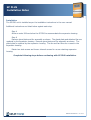
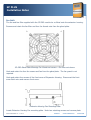
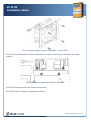
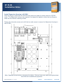
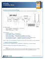
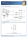
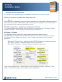
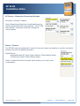
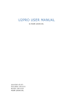
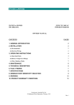
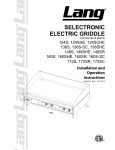
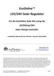
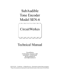
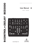
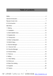
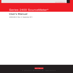
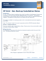
SP PLUS
Installation Notes
SP Grid - Gen Backup Installation Notes
Introduction
SP Grid – Generator Backup Installation Notes detail the addition of the Expansion Housing and
connection to the grid and an automatic backup generator to the SP PRO. The Expansion
Housing secures to and extends below the SP PRO unit and contains the additional components
required. The expansion housing allows for the bottom and rear cable entry.
This system is suitable for a backup generator which is automatically started and stopped by
the SP PRO.
Note: This document needs to be read in conjunction with the SP PRO Instruction Manual
SP GRID – GEN BACKUP MODELS
There is a model for each nominal battery voltage. Ensure you use the correct model to match
the system nominal battery voltage.
Wiring Overview
The following is an overview of the internal and external connections which form part of the
Grid – Gen Backup Expansion housing.
Note: Diagram is appliucable for both 24V and 48V models.
IN0015 Revision 01 – 1 of 11
POWER
PERFORMANCE
PASSION
SP PLUS
Installation Notes
Installation
The SP PRO unit is installed as per the installation instructions in the user manual.
Additional instructions are listed below against each step.
Step 4
Allow an extra 300mm below the SP PRO to accommodate the expansion housing.
Step 6
Remove gland plate and fan assembly as shown. The gland plate and attached fan are
replaced by the expansion housing. Remove gland plate and fan assembly as shown. The
gland plate is replaced by the expansion housing. The fan and fan filter are re-used in the
expansion housing.
Retain two side screws and loosen internal screws for re-use retaining expansion
housing.
Complete following steps before continuing with SP PRO installation.
IN0015 Revision 01 – 2 of 11
SP PLUS
Installation Notes
Fan Refit
The fan and fan filter supplied with the SP PRO need to be re-fitted onto the extension housing.
Remove and retain the fan filter and four fan thumb nuts from the gland plate.
SP PRO Gland Plate Showing Fan Guard and screws – Fan filter not shown.
Undo and retain the four fan screws and fan from the gland plate. The fan guard is not
required.
Undo and retain four screws of the front cover of Expansion Housing. Disconnect the front
cover Earth wire and remove front cover.
Extension Housing Fan Mounting Plate
Locate Extension Housing Fan mounting plate. Undo two retaining screws and remove plate.
IN0015 Revision 01 – 3 of 11
POWER
PERFORMANCE
PASSION
SP PLUS
Installation Notes
Fan mounting showing correct orientation – rotor visible
Fit fan to mounting plate as shown taking take to observe correct fan orientation and cable
position.
Fan assembly mounted into Extension Housing
Re-fit Fan Mounting plate into Expansion Housing.
Re-fit Fan Filter to bottom of expansion housing.
IN0015 Revision 01 – 4 of 11
SP PLUS
Installation Notes
Install Expansion Housing to SP PRO
Slide top flanges underneath the SP PRO base plate and guide the sides inside the SP PRO
cover. The Expansion housing may require to be tipped up slightly to allow the top flange to
slide into the internal retaining screws.
Tighten the internals screws and re-fit the two side screws to secure the Expansion Housing to
the SP PRO.
Note: Supplied internal wiring not shown for clarity. Picture shows rear cable entry gland plate
and DIN rail for additional equipment
IN0015 Revision 01 – 5 of 11
POWER
PERFORMANCE
PASSION
SP PLUS
Installation Notes
Expansion Housing Internal Wiring
The expansion housing contains additional internal wiring. Connect as detailed below
AC Source Wiring
Line (Red cable in black sleave) -> AC Source L
Neutral (Black) -> AC Source N
Earth (Green/Yellow) -> Earth
Control Wiring
Control Supply (Red) – Precharge B+
Control Supply (Brown) – Precharge BControl Input (Blue) -> Expansion Card Digital Ctrl In 4 POS
Control Input (Brown) -> Expansion Card Digital Ctrl In 4 NEG
Control Negative (Orange) -> Expansion Card Relay 3 NO (Normally Open)
Control Negative (Brown) -> Expansion Card Relay 3 Common
Note: It may be more convenient to fit Control cabling after all AC and DC wiring completed.
… continue SP PRO Installation
The SP PRO unit is installed as per the installation instructions in the user manual.
Additional instructions are listed below against each step.
Step 7
Battery Back Up loads connect into the AC Load L and N terminals within the SP PRO.
Only the expansion housing wiring connects into the SP PRO AC SOURCE terminals.
IN0015 Revision 01 – 6 of 11
SP PLUS
Installation Notes
Grid and Generator AC Wiring
The Grid and Generator is wired into the expansion housing as shown.
Note: AC circuit breakers and Earth Wires not shown for clarity.
Generator Control Wiring
The Generator Run control wiring is wired into the expansion card as shown. This configuration
is for a controller that require two wires to be closed to start and run and then opened to stop
the generator.
Note: Refer to Tech Note TN0025 for other control options.
IN0015 Revision 01 – 7 of 11
POWER
PERFORMANCE
PASSION
SP PLUS
Installation Notes
… continue SP PRO Installation
The SP PRO unit is installed as per the installation instructions in the user manual.
Additional instructions are listed below against each step.
Step 8
Once all wiring is completed, connect the front cover Earth wire and refit the expansion housing
cover using four screws. SP PRO cover plate removed prior to installation can be refitted and
will now secure to the expansion housing front cover.
SP PRO Configuration – Additional Configuration Settings
The following details the additional settings required to activate the Grid / Generator backup
hardware installed. This is in addition to settings for grid operation.
AC SOURCE – AC INPUT
The Alternative Source must set to accommodate the different power limit and
voltage/frequency range that the SP PRO will accept when the backup generator is running.
The Primary Source settings are shown by why of comparison between grid and backup
generator.
Alternate AC Source Power – maximum power SP PRO will draw from backup generator
Min, Max AC Voltage – allowable voltage range from generator
Min, Max AC Frequency – allowable frequency range from generator
Note: Default Values shown - Adjust values to suit the backup generator. External CT and
Extern. Contactor/CT settings are not used in this configuration.
IN0015 Revision 01 – 8 of 11
SP PLUS
Installation Notes
AC SOURCE – GENERATOR CONTROLLER SETTINGS
Generator Controller: Enabled
Note: Remaining settings can be adjusted based on
specific backup generator requirements. See SP PRO
User Manual – Generator Controller Settings for
further details.
INPUTS / OUTPUTS
The SP PRO must be configured to control the correct inputs and outputs to monitor and switch
between the grid and backup generator.
Digital Inputs –
Normal/Alternate AC Input Power Selector: Follow Backup Select
Inhibit Export Input: Follow Backup Select
Note: Low Batt Shut Down Override Input setting is not used in this
configuration.
IN0015 Revision 01 – 9 of 11
POWER
PERFORMANCE
PASSION
SP PLUS
Installation Notes
Grid Fail Generator Backup –
Grid Fail Backup: Enabled
Grid Available Input: Digital Control Input 4
Backup Select Output: Relay Output 3
Generator Outputs –
Generator Run Output – Relay Output 1
The actual generator output type used will depend on what signal is
required by the backup generator to start and stop. Refer to generator
documentation for details.
Note: Default settings shown. Start Output is not used in this
configuration.
SP PRO Configuration – Automatic Generator Control
The generator will run upon loss of grid supply on the default settings based on low battery
voltage or SoC if enabled. If you wish to enhance this operation, consult SP PRO User manual
– Generator Automatic Start for full details.
IN0015 Revision 01 – 10 of 11
SP PLUS
Installation Notes
Reference Information
RL1 - VOLTAGE MONITOR
The internal voltage monitor(RL1) is factory set and should not be adjusted. The factory
setting is detailed below:
: + 15 %
:-8%
:3s
: DIP-switches – under cover –
1
2
3
4
5
6
–
–
–
–
–
–
ON (DEL-REC)
OFF (N.E.)
ON (6 s)
OFF (INHIBIT)
ON (230 VAC)
OFF (230 VAC)
WARNING: Do not open the DIP-switches cover if the Power Supply is ON.
Additional Information
SP PRO web site – http://www.sppro.com.au or contact the Selectronic Sales Team.
+61 3 9727 6600
www.selectronic.com.au
IN0015 Revision 01 – 11 of 11
POWER
PERFORMANCE
PASSION