1
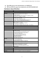
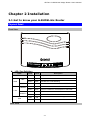
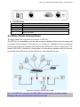
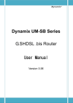
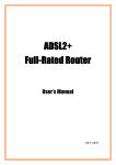
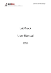
G.SHDSL.bis Bridge Router GRT-501 GRT-501 G.SHDSL.bis Bridge Router User’s Manual Copyright Copyright© 2007 by PLANET Technology Corp. All rights reserved. No part of this publication may be reproduced, transmitted, transcribed, stored in a retrieval system, or translated into any language or computer language, in any form or by any means, electronic, mechanical, magnetic, optical, chemical, manual or otherwise, without the prior written permission of PLANET. PLANET makes no representations or warranties, either expressed or implied, with respect to the contents hereof and specifically disclaims any warranties, merchantability or fitness for any particular purpose. Any software described in this manual is sold or licensed "as is". Should the programs prove defective following their purchase, the buyer (and not this company, its distributor, or its dealer) assumes the entire cost of all necessary servicing, repair, and any incidental or consequential damages resulting from any defect in the software. Further, this company reserves the right to revise this publication and to make changes from time to time in the contents hereof without obligation to notify any person of such revision or changes. All brand and product names mentioned in this manual are trademarks and/or registered trademarks of their respective holders. Disclaimer PLANET Technology does not warrant that the hardware will work properly in all environments and applications, and makes no warranty and representation, either implied or expressed, with respect to the quality, performance, merchantability, or fitness for a particular purpose. PLANET has made every effort to ensure that this User’s Manual is accurate; PLANET disclaims liability for any inaccuracies or omissions that may have occurred. Information in this User’s Manual is subject to change without notice and does not represent a commitment on the part of PLANET. PLANET assumes no responsibility for any inaccuracies that may be contained in this User’s Manual. PLANET makes no commitment to update or keep current the information in this User’s Manual, and reserves the right to make improvements to this User’s Manual and/or to the products described in this User’s Manual, at any time without notice. If you find information in this manual that is incorrect, misleading, or incomplete, we would appreciate your comments and suggestions. Trademarks The PLANET logo is a trademark of PLANET Technology. This documentation may refer to numerous hardware and software products by their trade names. In most, if not all cases, these designations are claimed as trademarks or registered trademarks by their respective companies. CE mark Warning This is a class B device, in a domestic environment; this product may cause radio interference, in which case the user may be required to take adequate measures. Federal Communication Commission Interference Statement This equipment has been tested and found to comply with the limits for a Class B digital device, pursuant to Part 15 of FCC Rules. These limits are designed to provide reasonable protection against harmful interference in a residential installation. This equipment generates, uses, and can radiate radio frequency energy and, if not installed and used in accordance with the instructions, may cause harmful interference to radio communications. However, there is no guarantee that interference will not occur in a particular installation. If this equipment does cause harmful interference to radio or television reception, which can be determined by turning the equipment off and on, the user is encouraged to try to correct the interference by one or more of the following measures: 1. Reorient or relocate the receiving antenna. 2. Increase the separation between the equipment and receiver. 3. Connect the equipment into an outlet on a circuit different from that to which the receiver is connected. 4. Consult the dealer or an experienced radio technician for help. -1- GRT-501 G.SHDSL.bis Bridge Router User’s Manual FCC Caution: To assure continued compliance (example-use only shielded interface cables when connecting to computer or peripheral devices). Any changes or modifications not expressly approved by the party responsible for compliance could void the user’s authority to operate the equipment. This device complies with Part 15 of the FCC Rules. Operation is subject to the Following two conditions: (1) This device may not cause harmful interference, and (2) this Device must accept any interference received, including interference that may cause undesired operation. R&TTE Compliance Statement This equipment complies with all the requirements of DIRECTIVE 1999/5/EC OF THE EUROPEAN PARLIAMENT AND THE COUNCIL OF 9 March 1999 on radio equipment and telecommunication terminal Equipment and the mutual recognition of their conformity (R&TTE) The R&TTE Directive repeals and replaces in the directive 98/13/EEC (Telecommunications Terminal Equipment and Satellite Earth Station Equipment) As of April 8, 2000. WEEE Caution To avoid the potential effects on the environment and human health as a result of the presence of hazardous substances in electrical and electronic equipment, end users of electrical and electronic equipment should understand the meaning of the crossed-out wheeled bin symbol. Do not dispose of WEEE as unsorted municipal waste and have to collect such WEEE separately. Safety This equipment is designed with the utmost care for the safety of those who install and use it. However, special attention must be paid to the dangers of electric shock and static electricity when working with electrical equipment. All guidelines of this and of the computer manufacture must therefore be allowed at all times to ensure the safe use of the equipment. Customer Service For information on customer service and support for the Multi-Homing Security Gateway, please refer to the following Website URL: http://www.planet.com.tw Before contacting customer service, please take a moment to gather the following information: ♦ The GRT-501 serial number and MAC address ♦ Any error messages that displayed when the problem occurred ♦ Any software running when the problem occurred ♦ Steps you took to resolve the problem on your own Revision User’s Manual for PLANET G.SHDSL.bis Bridge Router Model: GRT-501 Rev: 1.0 (Octorber, 2007) Port No. EM-GRT501v1 -2- GRT-501 G.SHDSL.bis Bridge Router User’s Manual Table of Contents TABLE OF CONTENTS ...................................................................................................................3 CHAPTER 1 OVERVIEW................................................................................................................5 PRODUCT FEATURES.......................................................................................................................... 5 HARDWARE SPECIFICATION ............................................................................................................... 6 PACKAGE CONTENTS ......................................................................................................................... 7 CHAPTER 2 INSTALLATION ........................................................................................................8 2.1 GET TO KNOW YOUR G.SHDSL.BIS ROUTER ............................................................................... 8 2.2 REAR PANEL CONNECTIONS ........................................................................................................ 9 2.3 SETTING UP THE HARDWARE ENVIRONMENT .............................................................................. 10 CHAPTER 3 LOGON PROCEDURE........................................................................................... 11 3.1 SERIAL CONSOLE ....................................................................................................................... 11 3.2 TELNET ..................................................................................................................................... 11 3.3 WEB BROWSER .......................................................................................................................... 12 CHAPTER 4 CONFIGURATION BY WEB BROWSER ...........................................................13 4.1 BASIC SETTING ......................................................................................................................... 13 4.1.1 Bridge Mode......................................................................................................................13 4.1.2 Routing Mode for PPPoA and PPPoE with IP Sharing ...................................................15 4.1.3 Routing Mode for IPoA or EoA.........................................................................................17 4.1.4 LAN-to-LAN Connection with Bridge Mode.....................................................................19 4.2 ADVANCED SETUP ..................................................................................................................... 21 4.2.1 SHDSL.bis .........................................................................................................................21 4.2.2 WAN...................................................................................................................................22 4.2.3 Bridge................................................................................................................................24 4.2.4 VLAN .................................................................................................................................25 4.2.5 ETHERNET.......................................................................................................................26 4.2.6 Route .................................................................................................................................27 4.2.7 NAT/DMZ..........................................................................................................................29 4.2.8 Virtual Server ....................................................................................................................31 4.3 STATUS ...................................................................................................................................... 32 4.4 ADMINISTRATION ...................................................................................................................... 33 4.4.1 Security..............................................................................................................................33 4.4.2 SNMP ................................................................................................................................34 4.4.3 Time Sync ..........................................................................................................................36 4.5 UTILITY ..................................................................................................................................... 38 -3- GRT-501 G.SHDSL.bis Bridge Router User’s Manual 4.5.1 System Info ........................................................................................................................38 4.5.2 Config Tool........................................................................................................................38 4.5.3 Upgrade ............................................................................................................................39 4.5.4 Logout ...............................................................................................................................40 4.5.5 Restart ...............................................................................................................................40 APPENDIX A: VLAN......................................................................................................................41 SPECIFICATION .............................................................................................................................. 41 FRAME SPECIFICATION ................................................................................................................. 42 APPLICATIONS ............................................................................................................................... 42 APPENDIX B: GLOSSARY ...........................................................................................................44 -4- Chapter 1 Overview The Planet new SHDSL family member GRT-501 is the G.SHDSL.bis router that complies with ITU-T G.991.2 standard and provides affordable, flexible, efficient Internet access solution for SOHO and Small Medium Business environment. The GRT-501 supports business-class, multi-range from 192kbps to 5.7Mbps (2-wire) symmetric data rates and also can be connected as the LAN-to-LAN network connection at the distance up to 6.7km (4.2 miles) by using existing telephone copper wires. The Planet GRT-501 is integrated high-end Bridging/Routing capabilities with advanced functions of DMZ, Virtual Server, and VPN pass-through. And because of the network environment growing rapidly, Virtual LAN has become more and more important feature in internetworking industry. The GRT-501 supports IEEE 802.1Q VLAN over ATM network. With the built-in Simple Network Management Protocol (SNMP) and web-based management, the GRT-501 offers an easy-to-use, platform-independent management and configuration facility. And the GRT-501 also provides Command-Line Interface; it can be accessed via Telnet and the console port. The network administrator can manage the device by proper way. Product Features High Speed Symmetric Data Transmission:The GRT-501 supports the latest G.SHDSL.bis technology, provides the higher symmetric data rate up to 5.7 Mbps on 2 wires. CO and CPE side Support:Provide the back-to-back connection. IEEE 802.1Q VLAN Support:The GRT-501 supports the IEEE 802.1Q Tagged VLAN, it offer significant benefit in terms with efficient use of bandwidth, flexibility, performance and security Bridge and Router Mode:The GRT-501 supports two connection modes. Currently, it comes pre-configured with routing mode. Note that, routing mode and bridging mode cannot be used simultaneously. Virtual Server:This feature allows Internet users to access Internet servers on your LAN. The required setup is quick and easy. VPN Pass through Support:PCs with VPN (Virtual Private Networking) software using PPTP, L2TP and IPSec are transparently supported - no configuration is required. DMZ Support:The GRT-501 can translate public IP addresses to private IP address to allow unrestricted 2-way communication with Servers or individual users on the Internet. This provides the most flexibility to run programs, which could be incompatible in NAT environment. RIPv1/v2 Routing:It supports RIPv1/v2 routing protocol for routing capability. Simple Network Management Protocol (SNMP):It is an easy way to remotely manage the router via SNMPv1/v2. GRT-501 G.SHDSL.bis Bridge Router User’s Manual Fully ATM protocol stack implementation over G.SHDSL.bis PPPoA and PPPoE support user authentication with PAP/CHAP/MS-CHAP Hardware Specification Product Model Hardware G.SHDSL.bis Bridge Router GRT-501 Standard Compliant with ITU-T G.991.2 Standard Annex A/B Compliant with G.SHDSL.bis Annex A/B/F/G TC-PAM Line Code Symmetric data transmission speed up to 5.7 Mbps on 2-wire Multi-range from 192kbps to 5.7Mbps RFC 1577 - Classical IP over ATM (RFC 1577) RFC 2364 - PPP over ATM RFC 1483/2684 - Ethernet over ATM RFC 2516 - PPP over Ethernet (fixed and dynamic IP) RFC 2364 - PPP over ATM (fixed and dynamic IP) Support up to 8PVCs ATM Forum UNI 3.1/4.0 PVC Support OAM F4 / F5 AIS/RDI and loopback VC multiplexing and SNAP/LLC Integrated ATM QoS support (UBR,CBR,VBR-rt, and VBR-nrt) 1 x 10Base-T/100Base-TX ( Auto-Negotiation, Auto MDI/MDI-X) 1 x RS-232 (DB9) 1 x Reset Button PWR, WAN LNK/ACT, LAN 10M/100M, ALM Protocol AAL and ATM Support LAN Port Console Button LED Indicators Software Protocol Security VPN IEEE 802.1D transparent learning bridge IEEE 802.1Q VLAN Support IP/TCP/UDP/ARP/ICMP/IGMP protocols IP routing with static routing and RIPv1/RIPv2 IP multicast and IGMP proxy Network address translation (NAT/PAT) DMZ host/Multi-DMZ/Multi-NAT function Virtual Server (RFC1631) DNS relay and caching DHCP server, client and relay Built-in NAT Firewall PPP over PAP (RFC1334) PPP over CHAP (RFC1994) Password protection for system management VPN (PPTP/L2TP/IPSec) pass-through Web-based configuration Command-line Interpreter(CLI) via Console Command-line Interpreter(CLI) via Telnet Software upgrade via web-browser/TFTP server SNMPv1 and v2 Environment Specification Dimension (W x D x H) 145 x 188 x 33mm Power 9V DC, 1A Operating: 0~45 degree C, 0%~ 90% (non-condensing), Temperature: Humidity Storage: -10~70 degree C, 0~95% (non-condensing) Emission FCC, CE Management -6- GRT-501 G.SHDSL.bis Bridge Router User’s Manual Package Contents The following items should be included. If any of these items are damaged or missing, please contact your dealer immediately. GRT-501 G.SHDSL.bis Bridge Router x 1 Power Adapter x 1 Quick Installation Guide x 1 User’s manual CD x 1 Console Cable x 1 RJ-45 to RJ-11 Cable x 1 -7- GRT-501 G.SHDSL.bis Bridge Router User’s Manual Chapter 2 Installation 2.1 Get to know your G.SHDSL.bis Router Physical Detail Front View LED / Port Definition LEDs Color Active PWR Green ON The power adaptor is connected to GRT-501 Green ON G.SHDSL.bis connection is established Green Blink G.SHDSL.bis is handshaking Green Blink Transmit data or receive data over G.SHDSL.bis link Green ON Green Blink Green ON Green Blink Red ON Red Blink LNK WAN ACT 10M/ACT LAN 100M/ACT ALM Description LAN Port connect with 10M Ethernet link LAN Port Transmit or receive data in 10M mode LAN Port connect with 100M Ethernet link LAN Port Transmit or receive data in 100M mode G.SHDSL.bis line connection is dropped G.SHDSL.bis self test Rear View -8- GRT-501 G.SHDSL.bis Bridge Router User’s Manual Port Definition Port DC-IN LAN CONSOLE LINE RST Description Power connector with 9V DC 1.0A Ethernet 10/100BaseT for LAN port (RJ-45) RS- 232C (DB9) for system configuration and maintenance G.SHDSL.bis interface for WAN Port The reset button, the router restore the default settings when press this button until reboot. 2.2 Rear Panel Connections The figure shows the rear panel connections of GRT-501. The GRT-501 is a standalone and can able to place in desktop. All the external wiring shall be located at the rear panel. The LAN port is a 10 Base-T / 100Base-TX auto-sensing and half/full duplex Ethernet interface and complied with IEEE 802.3 / 802.3u respectively. The console (RS-232C) interface for configuration is menu-driven operation and can also be configured through Ethernet interface by Telnet or Web-based operation. Figure 2-1 Connection with Switch or HUB Note: The GRT-501 supports auto MDI / MDI-X switching hub, so both straight through and cross-over Ethernet cable can be used. -9- GRT-501 G.SHDSL.bis Bridge Router User’s Manual 2.3 Setting up the hardware environment Step 1. Connect the power adapter to the port labeled DC-IN on the rear panel. Step 2. Connect the Ethernet cable between the LAN port and PC. Step 3. Connect male end of RS-232 cable to the console port and female end to any free COM port in PC. Step 4. Connect the phone cable to the Line port, and the other side of phone cable connects to wall jack. Step 5. Connect the power adapter to power source. Step 6. Turn on the PC or NB, which is used for configuration the Router. - 10 - GRT-501 G.SHDSL.bis Bridge Router User’s Manual Chapter 3 Logon Procedure This chapter provides information about how to logon the GRT-501. Note: After you have completed all necessary setting for GRT-501, make sure to write the new configuration to NVRAM by “write” command and reboot the system, or all of your changes will not take effect. There are three methods to logon to GRT-501: serial console, Telnet, and web interface. For the first time configuration, perhaps only the serial console mode could be used because applications requiring Internet protocol (IP) communication, such as Telnet and web interface, are not available unless a management IP is configured properly for your local networking environment. After connecting all the necessary cables described in Chapter 2 Installation, power on GRT-501 and select one of the following procedures to access GRT-501. Note: It is recommended that only one configuration application is used to setup GRT-501 at any given time, that is, Telnet, serial console and the web management interfaces should not be used simultaneously. 3.1 Serial console Check the connectivity of the RS-232 cable from your computer to the serial port of GRT-501. Start your terminal access program with VT100 terminal emulation. Configure the serial link with baud rate of 9600, 8 data bits, no parity check, 1 stop bit, and no flow-control, and press the SPACE key until the login screen appears. When you see the login screen, enter the correct user and password and then you can logon to GRT-501. User: admin Password: ***** Note: If you have not set any user profile for GRT-501, enter the factory default user “admin” and password “admin” to logon the device. 3.2 Telnet Make sure the correct Ethernet cable is used for connecting the LAN port of your computer to GRT-501. The LAN LNK indicator on the front panel shall light if a correct cable is used. Starting your Telnet client with VT100 terminal emulation and connecting to the management IP of GRT-501(192.168.0.1 is the default IP), wait for the login screen appears. When you see the login screen, enter the correct user and password and then you can logon to GRT-501. - 11 - GRT-501 G.SHDSL.bis Bridge Router User’s Manual User: admin Password: ***** Note: The factory default management IP and subnet mask are 192.168.0.1 and 255.255.255.0. If you have not set any user profile for GRT-501, enter the factory default user “admin” and password “admin” to logon the device. 3.3 Web browser Make sure the correct Ethernet cable is used for connecting the LAN port of your computer to GRT-501. The LAN LNK indicator on the front panel shall light if a correct cable is used. Starting your web browser and connecting to the management IP of GRT-501(192.168.0.1 is the default IP), wait for the login screen appears. When you see the login screen, enter the correct user and password and then you can logon to GRT-501. Open web browser and type http://192.168.0.1 in the browser's address box. This number is the default IP address for this device. Press Enter. A user name and password prompt will appear. The default username and password is “root”. Click OK button and you will login the GRT-501 for management. Note: The factory default management IP and subnet mask are 192.168.0.1 and 255.255.255.0. If you have not set any user profile for GRT-501, enter the factory default user “root” and password “root” to logon the device. - 12 - GRT-501 G.SHDSL.bis Bridge Router User’s Manual Chapter 4 Configuration by Web Browser 4.1 Basic Setting The Basic Setup contains LAN, WAN, Bridge and Route operation mode. User can use it to completely setup the router. After successfully completing it, you can access Internet. This is the easiest and possible way to setup the router. Note: The advanced functions are only for advanced users to setup advanced functions. The incorrect setting of advanced function will affect the performance or system error, even disconnection. 4.1.1 Bridge Mode Web UI Configuration Step 1. Click Basic on the left menu, the BASIC setting screen will display. And then select Bridge and CPE Side to setup Bridge mode of the Router and then click Next for the next setting. *This product can be setup as two G.SHDSL.bis working mode: CO (Central Office) and CPE (Customer Premises Equipment). For connection with DSLAM, the G.SHDSL.bis working mode is CPE. - 13 - GRT-501 G.SHDSL.bis Bridge Router User’s Manual Step 2. Enter Parameters in BASIC – TEP2: LAN IP: 192.168.0.1 Subnet Mask: 255.255.255.0 Gateway: 192.168.0.254 (The Gateway IP is provided by ISP) Host Name: SOHO Some of the ISP requires the Host Name as identification. You may check with ISP to see if your Internet service has been configured with a host name. In most cases, this field can be ignored. WAN1 VPI: 0 VCI: 32 Click LLC, and then Click Next for next setting. Step 3. The screen will prompt the new configured parameters. Check the parameters and click Restart. The router will reboot with the new setting or Continue to configure another parameters. - 14 - GRT-501 G.SHDSL.bis Bridge Router User’s Manual 4.1.2 Routing Mode for PPPoA and PPPoE with IP Sharing Web UI Configuration Step 1. For Route Mode with Point-to-Point Protocol over ATM and Ethernet, follow the following setting. First, select ROUTE and CPE Side, and then click Next for setting others parameters. Step 2. Enter Parameters in BASIC – STEP2: LAN IP: 192.168.0.1 Subnet Mask: 255.255.255.0 Host Name: SOHO The embedded DHCP server assigns network configuration information at most 253 users accessing the Internet in the same time. Click Next for next setting. - 15 - GRT-501 G.SHDSL.bis Bridge Router User’s Manual Step 3. Assign the IP pool for your DHCP server. Click Next. For example: If the LAN IP address is 192.168.0.1, the IP range of LAN is 192.168.0.2 to 192.168.0.51. The DHCP server assigns the IP form Start IP Address to End IP Address. The legal IP address range is form 0 to 255, but 0 are reserved as network name and 255 are reserved for broadcast. It implies the legal IP address range is from 1 to 254. That means you cannot assign an IP greater than 254 or less then 1. Lease time 72 hours indicates that the DHCP server will reassign IP information in every 72 hours. Step 4. Enter the Parameters in BASIC – STEP4 VPI: 0 VCI: 32 AAL5 Encapsulation: LLC Protocol: PPPoA + NAT or PPPoE + NAT Click Next to setup the ISP setting. Step 5. 1. Enter user name provided by ISP: test 2. Enter Password provided by ISP: test 3. Re-enter Password for confirmation: test The user name and password provided by your ISP. 4. Idle Time: 10 If you want your Internet connection to remain on at all time, enter 0 in the Idle Time field. 5. IP Type: Dynamic 6. Click Next. Step 6. The screen will prompt the new configured parameters. Check the parameters and click Restart. The router will reboot with the new setting or press Continue to configure another parameters. - 16 - GRT-501 G.SHDSL.bis Bridge Router User’s Manual 4.1.3 Routing Mode for IPoA or EoA Web UI Configuration Step 1. For Route Mode with IPoA and EoA, follow the following setting. First, select ROUTE and CPE Side, and then click Next for setting others parameters. Step 2. The embedded DHCP server assigns network configuration information at most 253 users accessing the Internet in the same time. Click Next for next setting. - 17 - GRT-501 G.SHDSL.bis Bridge Router User’s Manual Step 3. Assign the IP pool for your DHCP server. Click Next. For example: If the LAN IP address is 192.168.0.1, the IP range of LAN is 192.168.0.2 to 192.168.0.51. The DHCP server assigns the IP form Start IP Address to End IP Address. The legal IP address range is form 0 to 255, but 0 are reserved as network name and 255 are reserved for broadcast. It implies the legal IP address range is from 1 to 254. That means you cannot assign an IP greater than 254 or less then 1. Lease time 72 hours indicates that the DHCP server will reassign IP information in every 72 hours. Step 4. Enter Parameters in BASIC – STEP4 Wan Parameters; VPI: 0 VCI: 32 AAL5 Encapsulation: LLC Protocol: IPoA , EoA , IPoA + NAT or EoA + NAT Click Next to setup the IP parameters. Step 5. Enter Parameters in WAN setting. 1. IP Address: 10.1.2.1 2. Subnet mask: 255.255.255.0 3. Gateway: 10.1.2.2 Your ISP will provide above information to you. 4. DNS Server 1: 168.95.1.1 Your ISP will provide at least one DNS Server IP address. 5. Click Next. Step 6. The screen will prompt the new configured parameters. Check the parameters and click Restart. The router will reboot with the new setting or press Continue to configure another parameters. - 18 - GRT-501 G.SHDSL.bis Bridge Router User’s Manual 4.1.4 LAN-to-LAN Connection with Bridge Mode Web UI Configuration STU-R (CO) side Step 1. Click Bridge and CO Side to setup Bridge mode of the Router and then click Next. Step 2. Enter LAN Parameters 1. IP: 192.168.0.1 2. Subnet Mask: 255.255.255.0 3. Gateway: 192.168.0.2 Host Name: SOHO Enter WAN Parameters 1. VPI: 0 2. VCI: 32 3. Encapsulation: LLC 4. Click Next Step 3. The screen will prompt the new configured parameters. Check the parameters and Click Restart The router will reboot with the new setting or press Continue to configure another parameters. - 19 - GRT-501 G.SHDSL.bis Bridge Router User’s Manual STU-C (CPE) side Step 1. Click Bridge and CPE Side to setup Bridge mode of the Router and then click Next. Step 2. Enter LAN Parameters 1. IP: 192.168.0.2 2. Subnet Mask: 255.255.255.0 3. Gateway: 192.168.0.1 Host Name: SOHO Enter WAN Parameters 1. VPI: 0 2. VCI: 32 3. Encapsulation: LLC 4. Click Next Step 3. The screen will prompt the new configured parameters. Check the parameters and Click Restart. The router will reboot with the new setting or press Continue to configure another parameters.. After rebooting, the GRT-501 will establish a connection and the PC1 and PC2 can access to each other. - 20 - GRT-501 G.SHDSL.bis Bridge Router User’s Manual 4.2 Advanced Setup Advanced configuration contains SHDSL.bis, WAN, Bridge, VLAN, Ethernet, Route, NAT/DMZ and Virtual Server settings. 4.2.1 SHDSL.bis Web UI Configuration Step 1. You can setup the Annex type, data rate and SNR margin for SHDSL.bis parameters in SHDSL.bis. Click SHDSL.bis Step 2. Annex Type: There are foure Annex types, Annex A (ANSI), Annex B (ETSI), AnnexAF and Annex BG in SHDSL.bis. Check with your ISP about it. TCPAM Type: The default option is Auto. You may assign the different type manually by click the caption TPCAM-16 or TPCAM-32 Data Rate : you can setup the SHDSL.bis data rate in the multiple of 64kbps. The default data rate is 5696Kbps (n=89). Under Annex F/G TCPAM32 : data rate is 768Kbps ~ 5696Kbps (Nx64kbps, N=12~89) TCPAM16 : data rate is 192Kbps ~ 3840Kbps (Nx64kbps, N=3~60) Under Annex A/B TCPAM16 : 192Kbps ~ 2304Kbps (Nx 64kbps, N=3~36) For adaptive mode, you have to setup n=0. The router will adapt the data rate according to the line status. Step 3. The screen will prompt the parameters that will be written in EPROM. Check the parameters before writing in EPROM. Press Restart to restart the router working with new parameters or press Continue to setup another parameter. - 21 - GRT-501 G.SHDSL.bis Bridge Router User’s Manual 4.2.2 WAN The GRT-501 supports up to 8 PVCs. WAN 1 was configured via BASIC except QoS. If you want to setup the PVC 2 to 7, the parameters are setup in the page of WAN under ADVANCED. On the other hand, you do not need to setup WAN except you apply two or more Internet Services with ISPs. Web UI Configuration Step 1. Click WAN under the Advanced menu for configure the WAN parameters. Step 2. Enter the parameters: If WAN Protocol is PPPoA or PPPoE with dynamic IP, leave the default WAN IP Address and Subnet Mask as default setting. The system will ingore the IP Address and Subnet Mask information, but erasion or blank in default setting will cause system error. If the WAN Protocol is IPoA or EoA, leave the ISP parameters as default setting. The system will ingore the information, but erasion or blank in default setting will cause system error. QoS (Quality of Service): The Traffic Management Specification V4.0 defines ATM service cataloges that describe both the traffic transmitted by users onto a network as well as the Quailty of Service that the network need to provide for that traffic. UBR (Unspecified Bit Rate) is the simplest service provided by ATM networks. There is no guarantee of anything. It is a primary service used for transferring Internet traffic over the ATM network. CBR (Constant Bit Rate) is used by connections that requires a static amount of bandwidth that is avilable during the connection life time. This bandwidth is characterized by Peak Cell Rate (PCR). Based on the PCR of the CBR traffic, specific cell slots are assigned for the VC in the schedule table. The ATM always sends a signle cell during the CBR connection’s assigned cell slot. VBR-rt (Varible Bit Rate real-time) is intended for real-time applications, such as compressed voice over IP and video comferencing, that require tightly constrained delays and delay variation. VBR-rt is characterized by a peak cell rate (PCR), substained cell rate (SCR), and maximun burst rate (MBR). VBR-nrt (Varible Bit Rate non-real-time) - 22 - GRT-501 G.SHDSL.bis Bridge Router User’s Manual PCR (Peak Cell Rate) in kbps: The maximum rate at which you expect to transmit data, voice and video. Consider PCR and MBS as a menas of reducing lantency, not increasing bandwidth. The range of PCR is 64kbps to 2400kbps SCR (Substained Cell Rate): The sustained rate at which you expect to transmit data, voice and video. Consider SCR to be the true bandwidth of a VC and not the lone-term average traffic rate. The range of SCR is 64kbps to 2400kbps. MBS (Maximum Burst Size): The amount of time or the duration at which the router sends at PCR. The range of MBS is 1 cell to 255 cells. Step 3. Press Finish to finish setting. The screen will prompt the parameters that will be written in EPROM. Check the parameters before writing in EPROM. Press Restart to restart the router working with new parameters or press Continue to setup another parameter. - 23 - GRT-501 G.SHDSL.bis Bridge Router User’s Manual 4.2.3 Bridge If you want to setup advanced filter function while GRT-501 is working in bridge mode, you can use BRIDGE menu to setup the filter function, blocking function. Web UI Configuration Step 1. Click Bridge to start Bridge configuration. Step 2. Press Add in the bottom of web page to add the static bridge information. If you want to filter the designated MAC address of LAN PC to access Internet, press Add to establish the filtering table. Put the MAC address in MAC Address field and select Filter in LAN field. If you want to filter the designated MAC address of WAN PC to access LAN, press Add to establish the filtering table. Key the MAC address in MAC Address field and select Filter in WAN field. For example: If your VC is setup at WAN 1, select WAN 1 Filter. Step 3. Press Finish to finish setting. The screen will prompt the parameters that will be written in EPROM. Check the parameters before writing in EPROM. Press Restart to restart the router working with new parameters or press Continue to setup another parameter. - 24 - GRT-501 G.SHDSL.bis Bridge Router User’s Manual 4.2.4 VLAN Virtual LAN (VLAN) is defined as a group of devices on one or more LANs that are configured so that they can communicate as if they were attached to the same wire, when in fact they are located on a number of different LAN segments. Because VLAN is based on logical instead of physical connections, it is extremely flexible. Web UI Configuration Step 1. Click VLAN to configure VLAN settings. Step 2. The product support two types of VLAN: 1. 802.1Q Tag-Based VLAN 2. Port-Based VLAN. User can configure one of them to the router. For setting 802.1Q VLAN click the 802.1Q Tag-Based VLAN. The screem will prompt as follow. Step 3. VID: Virtual LAN ID. It is an definite number of ID which number is from 1 to 4094. PVID: Port VID which is an untagged member of default VLAN. Link Type: Access means the port can receive or send untagged packets. Trunk means that the port can receive or send tagged packets. - 25 - GRT-501 G.SHDSL.bis Bridge Router User’s Manual Step 4. Port-Based VLANs are VLANs where the packet forwarding decision is based on the destination MAC address and its associated port. Click Port-Based VLAN to configure the router. Step 5. Press Finish to finish setting. The screen will prompt the parameters that will be written in EPROM. Check the parameters before writing in EPROM. Press Restart to restart the router working with new parameters or press Continue to setup another parameter. 4.2.5 ETHERNET This page of function let user configure the media type of Ethernet. Web UI Configuration Step 1. Click ETHERNET to configure Ethernet. Here are several options: 1. AutoSense 2. 100Base-TX full duplex 3. 100Base-TX helf duplex 4. 10Base-T full duplex 5. 10Base-T helf duplex Step 2. Press Finish to finish setting. The screen will prompt the parameters that will be written in EPROM. Check the parameters before writing in EPROM. Press Restart to restart the router working with new parameters or press Continue to setup another parameter. - 26 - GRT-501 G.SHDSL.bis Bridge Router User’s Manual 4.2.6 Route If the GRT-501 is connected to more than one network, it may be necessary to set up a static route between them. A static route is a pre-determined pathway that network information must travel to reach a specific host or network. With Dynamic Routing, you can enable the GRT-501 to automatically adjust to physical changes in the network’s layout. The Router, using the RIP protocol, determines the network packets’ route based on the fewest number of hops between the source and the destination. The RIP protocol regularly broadcasts routing information to other routers on the network. Web UI Configuration Step 1. Click Route to modify the routing information. Step 2. To modify the RIP (Routing information protocol) Parameters: RIP Mode: Enable Auto RIP Summary: Enable Press Modify - 27 - GRT-501 G.SHDSL.bis Bridge Router User’s Manual Step 3. RIP Mode: This parameter determines how the product handle RIP (Routing information protocol). RIP allows it to exchange routing information with other router. If set to Disable, the gateway does not participate in any RIP exchange with other router. If set Enable, the router broadcasts the routing table of the router on the LAN and incoporates RIP broadcast by other routers into it’s routing table. If set silent, the router does not broadcast the routing table, but it accepts RIP broadcast packets that it receives. Step 4. RIP Version: It determines the format and broadcasting method of any RIP transmissions by the gateway. RIP v1: it only sends RIP v1 messages only. RIP v2: it send RIP v2 messages in multicast and broadcast format. Step 5. Authentication required: None: for RIP, there is no need of authentication code. Password: the RIP is protected by password, authentication code. MD5: The RIP will be decoded by MD5 than protected by password, authentication code. Step 6. Poison Reserve is for the purpose of promptly broadcast or multicast the RIP while the route is changed. (ex shuting down one of the routers in routing table) Enable: the gateway will actively broadcast or multicast the information. Disable: the gateway will not broadcast or multicast the information. Step 7. After modifying the RIP parameters, press OK . Check the settings are correct and then press finish. - 28 - GRT-501 G.SHDSL.bis Bridge Router User’s Manual The screen will prompt the modified parameter. Check the parameters and perss Restart to restart the router or press Continue to setup another parameters. 4.2.7 NAT/DMZ NAT (Network Address Translation) is the translation of an Internet Protocol address (IP address) used within one network to a different IP address known within another network. One network is designated the inside network and the other is the outside. Typically, a company maps its local inside network addresses to one or more global outside IP addresses and reverse the global IP addresses of incoming packets back into local IP addresses. This ensure security since each outgoing or incoming request must go through a translation process, that also offers the opportunity to qualify or authenticate the request or match it to a previous request. NAT also conserves on the number of global IP addresses that a company needs and lets the company to use a single IP address of its communication in the Internet world. DMZ (demilitarized zone) is a computer host or small network inserted as a “neutral zone” between a company private network and the outside public network. It prevents outside users from getting direct access to a server that has company private data. In a typical DMZ configuration for an enterprise, a separate computer or host receives requests from users within the private network to access via Web sites or other companies accessible on the public network. The DMZ host then initiates sessions for these requests to the public network. However, the DMZ host is not able to initiate a session back into the private network. It can only forward packets that have already been requested. Users of the public network outside the company can access only the DMZ host. The DMZ may typically also have the company’s Web pages so these could serve the outside world. However, the DMZ provides access to no other company data. In the event that an outside user penetrated the DMZ host’s security, the Web pages might be corrupted, but no other company information would be exposed. Web UI Configuration - 29 - GRT-501 G.SHDSL.bis Bridge Router User’s Manual Step 1. Press NAT/DMZ to setup the parameters. If you want to enable the NAT/DMZ functions, click Enable. Enable the DMZ host Function is used the IP address assigned to the WAN for enabling DMZ function for the virtual IP address. Multi-DMZ: Some users who have two or more global IP addresses assigned by ISP can be used the multi DMZ. The table is for the mapping of global IP address and virtual IP address. Multi-NAT: Some of the virtual IP addresses (eg: 192.168.0.10 ~ 192.168.0.50) collectively use two of the global IP addresses (eg: 69.210.1.9 and 69.210.1.10). The Multi-NAT table will be setup as: Virtual Start IP Address: 192.168.0.10 Count: 40 Global Start IP Address: 69.210.1.9 Count: 2 Press Finish to continue. Step 2. The screen will prompt the parameters that will be written in EPROM. Check the parameters before writing in EPROM. Press Restart to restart the router working with new parameters or Continue to configure another parameter. - 30 - GRT-501 G.SHDSL.bis Bridge Router User’s Manual 4.2.8 Virtual Server For example: Specific ports on the WAN interface are re-mapped to services inside the LAN. As only 69.210.1.8 (e.g., assigned to WAN from ISP) is visible to the Internet, but does not actually have any services (other than NAT of course) running on gateway, it is said to be a virtual server. Request with TCP made to 69.210.1.8:80 are remapped to the server 1 on 192.168.0.2:80 for working days from Monday to Friday 8 AM to 6PM, other requests with UDP made to 69.210.1.8:25 are remapped to server 2 on 192.168.0.3:25 and always on. You can setup the router as Index 1, protocol TCP, interface WAN1, service name test1, private IP 192.168.0.2, private port 80, public port 80, schedule from Day Monday to Friday and time 8:0 to 16:0 and index 2, protocol UDP, interface WAN1, service name test2, private IP 192.168.0.3, private port 25, public port 25, schedule always. Web UI Configuration Step 1. Click Virtual Server to configure the parameters. Press Modify for modify #1. Step 2. Type the necessary parameters then click OK. For Example: Protocol: TCP Interface: WAN1 Service Name: FTP Private IP: 192.168.0.100 Private Port: 21 ~ 21 Public Port: 21 ~ 21 Schedule: Always - 31 - GRT-501 G.SHDSL.bis Bridge Router User’s Manual Step 3. Press Finish to continue. The screen will prompt the parameters that will be written in EPROM. Check the parameters before writing in EPROM. Press Restart to restart the router working with new parameters or press Continue to configure another parameter. 4.3 Status In Status function, you can monitor the status of device which includes SHDSL.bis, LAN, WAN, Ethernet, Route and Interface. SHDSL.bis status including mode, Tx power and Bitrate and Performance information including SNR margin, atteunation and CRC error count. LAN status will prompt the MAC address, IP address, Subnet mask and DHCP client table. WAN status will display the WAN interface information. Ethernet status will display the Media Type. ROUTE status can view the routing table in the device. INTERFACE status inculdes LAN and WAN statistics information. - 32 - GRT-501 G.SHDSL.bis Bridge Router User’s Manual 4.4 Administration This section introduces security and simple network management protocol (SNMP) and time synchronous. 4.4.1 Security For system security, suggest to change the default user name and password in the first setup otherwise unauthorized persons can access the router and change the parameters. There are three ways to configure the router, Web browser, telnet and serial console. Web UI Configuration Step 1. Press Security to setup the parameters. For greater security, change the Supervisor ID and password for the gateway. If you don’t set them, all users on your network can be able to access the gateway using the default IP and Password root. You can authorize five legal users to access the router via telnet or console. There are two UI modes, menu driven mode and command mode to configure the router. Legal address pool will setup the legal IP addresses from which authorized person can configure the gateway. This is the more secure function for network administrator to setup the legal address of configuration. - 33 - GRT-501 G.SHDSL.bis Bridge Router User’s Manual Step 2. Configured 0.0.0.0 will allow all hosts on Internet or LAN to access the router. Leaving blank of trust host list will cause blocking all PC from WAN to access the router. On the other hand, only PC in LAN can access the router. If you type the excact IP address in the filed, only the host can access the router. Click Finish to finish the setting Step 3. The browser will prompt the configured parameters and check it before writing into EPROM. Press Restart to restart the gateway working with the new parameters and press Continue to setup other parameters. 4.4.2 SNMP Simple Network Management Protocol (SNMP) provides for the exchange of messages between a network management client and a network management agent for remote management of network nodes. These messages contain requests to get and set variables that exist in network nodes in order to obtain statistics, set configuration parameters, and monitor network events. SNMP communications can occur over the LAN or WAN connection. The router can generate SNMP traps to indicate alarm conditions, and it relies on SNMP community strings to implement SNMP security. This router support both MIB I and MIB II. Web UI Configuration - 34 - GRT-501 G.SHDSL.bis Bridge Router User’s Manual Step 1. Click SNMP to configure the parameters. In the table of current community pool, you can setup the access authority. In the table of current trap host pool, you can setup the trap host. Press Modify to modify the community pool. Step 2. SNMP status: Enable Step 3. Access Right: Deny for deny all access Read for access read only Write for access read and write. Community: it serves as password for access right. After configuring the community pool, press OK. - 35 - GRT-501 G.SHDSL.bis Bridge Router User’s Manual Step 4. SNMP trap is an informational message sent from an SNMP agent to a manager. Click Modify to modify the trap host pool. Version: select version for trap host. (Version 1 is for SNMPv1; Version 2 for SNMPv2). IP Address: type the trap host IP address Community: type the community password. The community is setup in community pool. Press OK to finish the setup. Step 5. The browser will prompt the configured parameters and check it before writing into EPROM. Press Restart to restart the gateway working with the new parameters and press Continue to setup other parameters. 4.4.3 Time Sync Time synchronization is an essential element for any business, which relies on the IT system. The reason for this is that these systems all have clock that is the source of timer for their filing or operations. Without time synchronization, these system’s clocks vary and cause the failure of firewall packet filtering schedule processes, compromised security, or virtual server working in wrong schedule. Web UI Configuration Step 1. Click TIME SYNC. Synchronization modes (SYNC method): SNTP v4.0., Simple Network Time Protocol Sync with PC, synchronization with PC. For synchronization with PC, Select Sync with PC and press Sync Now. The gateway will synchronize the time with the connecting PC. - 36 - GRT-501 G.SHDSL.bis Bridge Router User’s Manual Step 2. SNTP is the acronym for Simple Network Time Protocol, which is an adaptation of the Network Time Protocol (NTP) used to synchronize computer clocks in the Internet. SNTP can be used when the ultimate performance of the full NTP implementation. For SNTP, select SNTP v4.0. Service: Enable Time Server 1: All of the time server around the world can be used but suggest using the timeserver nearby. Time Zone: you have to choose the right time zone. Step 3. Press Finish to finish the setup. The browser will prompt the configured parameters and check it before writing into EPROM. Press Restart to restart the gateway working with the new parameters and press Continue to setup other parameters. - 37 - GRT-501 G.SHDSL.bis Bridge Router User’s Manual 4.5 Utility This section will describe the utility of the product: SYSTEM INFO: System information, CONFIG TOOL: Load the factory default configuration, UPGRADE: Upgrade the firmware LOGOUT: Logout the system RESTART: Restart the router. 4.5.1 System Info Web UI Configuration Click System Info for review the information. The browser will prompt the system information. 4.5.2 Config Tool This configuration tool has three functions: load Factory Default, Restore Configuration, and Backup Configuration. - 38 - GRT-501 G.SHDSL.bis Bridge Router User’s Manual 1. Load Factory Default: It will load the factory default parameters to the gateway. Note: This action will change all of the settings to factory default. On the other hand, you will lose all the existing configured parameters. 2. 3. Restore Configuration: Sometime the configuration crushed occasionally. It will help you to recover the backup configuration easily. Click Finish after selecting Restore Configuration. Browse the route of backup file then press Finish. The router will automatically restore the saved configuration. Backup Configuration: After configuration, suggest using the function to backup your router parameters in the PC. Select the Backup Configuration and then press Finish. Browse the place of backup file named backup. Press Finish. The router will automatically backup the configuration. 4.5.3 Upgrade You can upgrade the Firmware by using the upgrade function. Press Upgrade in UTILITY. Browse the file and press OK button to upgrade. The system will reboot automatically after finishing. - 39 - GRT-501 G.SHDSL.bis Bridge Router User’s Manual 4.5.4 Logout To logout the router, press LOGOUT in UTILITY. The browser will prompt the logout window. Press Yes to logout GRT-501. 4.5.5 Restart For restarting the router, click the Restart in UTILITY. Press Restart to reboot the router. - 40 - GRT-501 G.SHDSL.bis Bridge Router User’s Manual Appendix A: VLAN Virtual LAN (VLAN) is defined as a group of devices on one or more LANs that are configured so that they can communicate as if they were attached to the same wire, when in fact they are located on a number of different LAN segments. Because VLAN is based on logical instead of physical connections, it is extremely flexible. The IEEE 802.1Q defines the operation of VLAN bridges that permit the definition, operation, and administration of VLAN topologies within a bridged LAN infrastructure. VLAN architecture benefits include: 1. 2. 3. 4. 5. Increased performance Improved manageability Network tuning and simplification of software configurations Physical topology independence Increased security options As DSL (over ATM) links are deployed more and more extensively and popularly, it is rising progressively to implement VLAN (VLAN-to-PVC) over DSL links and, hence, it is possible to be a requirement of ISPs. We discuss the implementation of VLAN-to-PVC only for bridge mode operation, i.e., the VLAN spreads over both the CO and CPE sides, where there is no layer 3 routing involved. Specification 1. The unit supports up to 8 active VLANs with shared VLAN learning (SVL) bridge out of 4096 possible VLANs specified in IEEE 802.1Q. 2. Each port always belongs to a default VLAN with its port VID (PVID) as an untagged member. Also, a port can belong to multiple VLANs and be tagged members of these VLANs. 3. A port must not be a tagged member of its default VLAN. 4. If a non-tagged or null-VID tagged packet is received, it will be assigned with the default PVID of the ingress port. 5. If the packet is tagged with non-null VID, the VID in the tag will be used. 6. The look up process starts with VLAN look up to determine whether the VID is valid. If the VID is not valid, the packet will be dropped and its address will not be learned. If the VID is valid, the VID, destination address, and source address lookups are performed. 7. The VID and destination address lookup determines the forwarding ports. If it fails, the packet will be broadcasted to all members of the VLAN, except the ingress port. 8. Frames are sent out tagged or untagged depend on if the egress port is a tagged or untagged member of the VLAN that frames belong. 9. If VID and source address look up fails, the source address will be learned. - 41 - GRT-501 G.SHDSL.bis Bridge Router User’s Manual Frame Specification An untagged frame or a priority-tagged frame does not carry any identification of the VLAN to which it belongs. Such frames are classified as belonging to a particular VLAN based on parameters associated with the receiving port. Also, priority tagged frames, which, by definition, carry no VLAN identification information, are treated the same as untagged frames. A VLAN-tagged frame carries an explicit identification of the VLAN to which it belongs; i.e., it carries a tag header that carries a non-null VID. This results in a minimum tagged frame length of 68 octets. Such a frame is classified as belonging to a particular VLAN based on the value of the VID that is included in the tag header. The presence of the tag header carrying a non-null VID means that some other device, either the originator of the frame or a VLAN-aware bridge, has mapped this frame into a VLAN and has inserted the appropriate VID. The following figure shows the difference between a untagged frame and VLAN tagged frame, where the Tag Protocol Identifier (TPID) is of 0x8100 and it identifies the frame as a tagged frame. The Tag Control Information (TCI) consists of the following elements: 1) User priority allows the tagged frame to carry user priority information across bridged LANs in which individual LAN segments may be unable to signal priority information (e.g., 802.3/Ethernet segments). 2) The Canonical Format Indicator (CFI) is used to signal the presence or absence of a Routing Information Field (RIF) field, and, in combination with the Non-canonical Format Indicator (NCFI) carried in the RIF, to signal the bit order of address information carried in the encapsulated frame. 3) The VID uniquely identifies the VLAN to which the frame belongs. Applications 1. Port Based VLAN Port Based VLAN Example - 42 - GRT-501 G.SHDSL.bis Bridge Router User’s Manual 2. 802.1Q VLAN 802.1Q VLAN Example - 43 - GRT-501 G.SHDSL.bis Bridge Router User’s Manual Appendix B: Glossary Address mask A bit mask select bits from an Internet address for subnet addressing. The mask is 32 bits long and selects the network portion of the Internet address and one or more bits of the local portion. Sometimes it called subnet mask. AAL5 ATM Adaptation Layer - This layer maps higher layer user data into ATM cells, making the data suitable for transport through the ATM network. ADSL Asymmetric digital subscriber line ATM Asynchronous Transfer Mode - A cell-based data transfer technique in which channel demand determines packet allocation. ATM offers fast packet technology, real time, and demand led switching for efficient use of network resources. AWG American Wire Gauge - The measurement of thickness of a wire Bridge A device connects two or more physical networks and forward packets between them. Bridges can usually be made to filter packets, that is, to forward only certain traffic. Related devices are repeaters which simply forward electrical signals from one cable to the other and full-fledged routers which make routing decisions based on several criteria. Broadband Characteristic of any network multiplexes independent network carriers onto a single cable. Broadband technology allows several networks to coexist on one single cable; traffic from one network does not interfere with traffic from another. Broadcast a packet delivery system where a copy of a given packet is given to all hosts attached to the network. Example: Ethernet. CO Central Office. Refers to equipment located at a Telco or service provider's office. CPE Customer Premises Equipment located in a user's premises - 44 - GRT-501 G.SHDSL.bis Bridge Router User’s Manual DHCP (Dynamic Host Configuration Protocol) DHCP is software that automatically assigns IP addresses to client stations logging onto a TCP/IP network. DHCP eliminates having to manually assign permanent IP addresses to every device on your network. DHCP software typically runs in servers and is also found in network devices such as Routers. DMT Discrete Multi-Tone frequency signal modulation Downstream rate The line rate for return messages or data transfers from the network machine to the user's premises machine. DSLAM Digital Subscriber Line Access Multiplex Dynamic IP Addresses A dynamic IP address is an IP address that is automatically assigned to a client station (computer, printer, etc.) in a TCP/IP network. Dynamic IP addresses are typically assigned by a DHCP server, which can be a computer on the network or another piece of hardware, such as the Router. A dynamic IP address may change every time your computer connects to the network. Encapsulation The technique layer protocols in which a layer adds header information to the protocol data unit (PDU) from the layer above. As an example, in Internet terminology, a packet would contain a header from the physical layer, followed by a header from the network layer (IP), followed by a header from the transport layer (TCP), and followed by the application protocol data. Ethernet One of the most common local area network (LAN) wiring schemes, Ethernet has a transmission rate of 10 Mbps. FTP File Transfer Protocol. The Internet protocol (and program) transfer files between hosts. Hop count A measure of distance between two points on the Internet. It is equivalent to the number of gateways that separate the source and destination. - 45 - GRT-501 G.SHDSL.bis Bridge Router User’s Manual HTML Hypertext Markup Language - The page-coding language for the World Wide Web. HTML browser A browser used to traverse the Internet, such as Netscape or Microsoft Internet Explorer. http Hypertext Transfer Protocol - The protocol carry world-wide-web (www) traffic between a www browser computer and the www server being accessed. ICMP Internet Control Message Protocol - The protocol handle errors and control messages at the IP layer. ICMP is actually part of the IP protocol. Internet address An IP address is assigned in blocks of numbers to user organizations accessing the Internet. These addresses are established by the United States Department of Defense's Network Information Center. Duplicate addresses can cause major problems on the network, but the NIC trusts organizations to use individual addresses responsibly. Each address is a 32-bit address in the form of x.x.x.x where x is an eight- bit number from 0 to 255. There are three classes: A, B and C, depending on how many computers on the site are likely to be connected. Internet Protocol (IP) The network layer protocol for the Internet protocol suite IP address The 32-bit address assigned to hosts that want to participate in a TCP/IP Internet. ISP Internet service provider - A company allows home and corporate users to connect to the Internet. MAC Media Access Control Layer - A sub-layer of the Data Link Layer (Layer 2) of the ISO OSI Model responsible for media control. MIB Management Information Base - A collection of objects can be accessed via a network management protocol, such as SNMP and CMIP (Common Management Information - 46 - GRT-501 G.SHDSL.bis Bridge Router User’s Manual Protocol). NAT Network Address Translation - A proposal for IP address reuse, where the local IP address is mapped to a globally unique address. NVT Network Virtual Terminal PAP Password Authentication Protocol PORT The abstraction used in Internet transport protocols to distinguish among multiple simultaneous connections to a single destination host. POTS Plain Old Telephone Service - This is the term describe basic telephone service. PPP Point-to-Point-Protocol - The successor to SLIP, PPP provides router-to-router and host-to-network connections over both synchronous and asynchronous circuits. PPPoE PPP over Ethernet is a protocol for connecting remote hosts to the Internet over an always-on connection by simulating a dial-up connection. Remote server A network computer allows a user to log on to the network from a distant location. RFC Request for Comments - Refers to documents published by the Internet Engineering Task Force (IETF) proposing standard protocols and procedures for the Internet. RFC can be found at www.ietf.org. Route The path that network traffic takes from its source to its destination. The route a datagram may follow can include many gateways and many physical networks. In the Internet, each datagram is routed separately. - 47 - GRT-501 G.SHDSL.bis Bridge Router User’s Manual Router A system is responsible for making decisions about which of several paths network (or Internet) traffic will follow. To do this, it uses a routing protocol to gain information about the network and algorithms to choose the best route based on several criteria known as "routing metrics". Routing Table Information stored within a router that contains network path and status information. It is used to select the most appropriate route to forward information along. Routing Information Protocol Routers periodically exchange information with one another so that they can determine minimum distance paths between sources and destinations. SNMP Simple Network Management Protocol - The network management protocol of choice for TCP/IP-based Internet. SOCKET (1) The Berkeley UNIX mechanism for creating a virtual connection between processes. (2) IBM term for software interfaces that allow two UNIX application programs to talk via TCP/IP protocols. Spanning-Tree Bridge Protocol (STP) Spanning-Tree Bridge Protocol (STP) - Part of an IEEE standard. A mechanism for detecting and preventing loops from occurring in a multi-bridged environment. When three or more LAN's segments are connected via bridges, a loop can occur. Because of a bridge forwards all packets that are not recognized as being local, some packets can circulate for long periods of time, eventually degrading system performance. This algorithm ensures only one path connects any pair of stations, selecting one bridge as the 'root' bridge, with the highest priority one as identifier, from which all paths should radiate. Spoofing A method of fooling network end stations into believing that keep alive signals have come from and returned to the host. Polls are received and returned locally at either end Static IP Address A static IP address is an IP address permanently assigned to computer in a TCP/IP network. - 48 - GRT-501 G.SHDSL.bis Bridge Router User’s Manual Static IP addresses are usually assigned to networked devices that are consistently accessed by multiple users, such as Server PCs, or printers. If you are using your Router to share your cable or DSL Internet connection, contact your ISP to see if they have assigned your home a static IP address. You will need that address during your Router's configuration. Subnet For routing purposes, IP networks can be divided into logical subnets by using a subnet mask. Values below those of the mask are valid addresses on the subnet. TCP Transmission Control Protocol - The major transport protocol in the Internet suite of protocols provides reliable, connection-oriented full-duplex streams. TFTP Trivial File Transfer Protocol. A simple file transfer protocol (a simplified version of FTP) that is often boot diskless workstations and other network devices such as routers over a network (typically a LAN). Telnet The virtual terminal protocol in the Internet suite of protocols - Allows users of one host to log into a remote host and act as normal terminal users of that host. Transparent bridging The intelligence necessary to make relaying decisions exists in the bridge itself and is thus transparent to the communicating workstations. It involves frame forwarding, learning workstation addresses, and ensuring no topology loops exist (in conjunction with the Spanning-Tree algorithm). UDP User Datagram Protocol - A connectionless transport protocol that runs on top of TCP/IP's IP. UDP, like TCP, uses IP for delivery; however, unlike TCP, UDP provides for exchange of datagram without acknowledgments or guaranteed delivery. Best suited for small, independent requests, such as requesting a MIB value from an SNMP agent, in which first setting up a connection would take more time than sending the data. UNI signaling User Network Interface signaling for ATM communications. - 49 - GRT-501 G.SHDSL.bis Bridge Router User’s Manual Virtual Connection (VC) A link that seems and behaves like a dedicated point-to-point line or a system that delivers packets in sequence, as happens on an actual point-to-point network. In reality, the data is delivered across a network via the most appropriate route. The sending and receiving devices do not have to be aware of the options and the route is chosen only when a message is sent. There is no pre-arrangement, so each virtual connection exists only for the duration of that one transmission. WAN Wide area network - A data communications network that spans any distance and is usually provided by a public carrier (such as a telephone company or service provider). - 50 - EC Declaration of Conformity For the following equipment: *Type of Product *Model Number : G..SHDSL.bis Router : GRT-501 * Produced by: Manufacturer‘s Name: Planet Technology Corp. Manufacturer‘s Address: 11F, No. 96, Min Chuan. Road, Hsin Tien Taipei, Taiwan, R.O.C. is herewith confirmed to comply with the requirements set out in the Council Directive on the Approximation of the Laws of the Member States relating to Electromagnetic Compatibility (89/336/EEC, Amended by 92/31/EEC, 93/68/EEC & 98/12/EC). For the evaluation regarding the Electromagnetic Compatibility, the following standards were applied: Emission EN 55022 Harmonic Flicker Immunity ESD RS EFT/ Burst Surge CS Magnetic Field Voltage Disp Safety EN 61000-3-2 EN 61000-3-3 EN 55024 EN 61000-4-2 EN 61000-4-3 EN 61000-4-4 EN 61000-4-5 EN 61000-4-6 IEC 61000-4-8 EN 61000-4-11 EN 60950 (1994 + A1:1995 + A2:1997 Class A) (2000) (1995 + A1:2001) (1998 + A1:2001 + A2:2003) (2001) (2002) (1995 + A1:2000 + A2:2001) (2001) (2001) (2001) (2001) (2000) Responsible for marking this declaration if the: ⌧ Manufacturer Authorized representative established within the EU Authorized representative established within the EU (if applicable): Company Name: Planet Technology Corp. Company Address: 11F, No.96, Min Chuan Road, Hsin Tien, Taipei, Taiwan, R.O.C Person responsible for making this declaration Name, Surname Allen Huang Position / Title : Product Manager Taiwan Place 20th Dec., 2007 Date Legal Signature PLANET TECHNOLOGY CORPORATION e-mail: [email protected] http://www.planet.com.tw 11F, No. 96, Min Chuan Road, Hsin Tien, Taipei, Taiwan, R.O.C. Tel:886-2-2219-9518 Fax:886-2-2219-9528