1
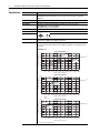
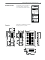
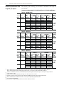
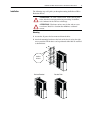
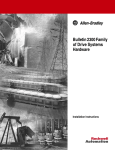
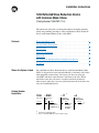
Installation Instructions
1204 Reflected Wave Reduction Device
with Common Mode Choke
(Catalog Number 1204-RWC-17-A)
This publication will guide you through installation (including mounting,
wiring and grounding procedures) of the 1204 Reflected Wave Reduction
Device with Common Mode Choke (1204-RWC).
Contents
Where this Option is Used . . . . . . . . . . . . . . . . . . . . . . . . . . . . . . . . . . . . .1
Catalog Number Explanation . . . . . . . . . . . . . . . . . . . . . . . . . . . . . . . . . . .1
Specifications . . . . . . . . . . . . . . . . . . . . . . . . . . . . . . . . . . . . . . . . . . . . . . .2
Nameplate Information . . . . . . . . . . . . . . . . . . . . . . . . . . . . . . . . . . . . . . .3
Dimensions . . . . . . . . . . . . . . . . . . . . . . . . . . . . . . . . . . . . . . . . . . . . . . . . .3
Determining the Maximum Cable Length for your System . . . . . . . . . . . .4
Installation . . . . . . . . . . . . . . . . . . . . . . . . . . . . . . . . . . . . . . . . . . . . . . . . .5
Where this Option is Used
Catalog Number
Explanation
The 1204 Reflected Wave Reduction Device with Common Mode Choke
(RWC) is designed to be used with Allen-Bradley 1336 family of AC drives
with compatible current ratings. Call factory for advice on using the
1204-RWC with drives other than the 1336 family of AC drive. When
installed near the drive, the device can reduce potentially destructive
reflected wave spikes that can occur with long motor leads and reduces the
effect of Common Mode noise.
(1)
1204
– RWC
– 17
First Position
Second Position
Third Position
Type
Current Rating
Mounting Config.
Code
Rating
Letter
Mounting
17.5 Amps at
380-480V,
12 Amps at
575-600V
A
Book Style (2)
Description
Letter
Description
Bulletin
Number
RWC Reflected Wave
17
Reduction Device
IP20 (NEMA Type 1)
(1)
Consult factory for 240V applications.
(2)
Chassis is rated IP20 (NEMA Type 1) for Book Style mounting.
–A
Fourth Position
1204 Reflected Wave Reduction Device with Common Mode Choke
I
ND
Heat Dissipation
CONT E
Above 1000 meters (3300 feet) derate at 6% of RWC rated amperes per 1000 meters (3300
feet) elevation to 4000 meters (13200 feet) maximum.
Use the cable length and drive carrier frequency to find the approximate RWC losses for your
system. Vertical movement inside the loss band will be dependent on exact cable type and
motor load.
Total Watts Loss
2 kHz Carrier Frequency
240
Total RWC Losses (Watts)
Altitude Derating
Q
LI
X
Input Power
380-600VAC, Three-Phase
Drive Carrier Frequency 2 kHz Recommended (used for most applications)
Important: 6kHz Absolute Maximum – Refer to Chart below and page 4 for application
restrictions.
Ambient Temperature
0-50 Degrees C (32-122 Degrees F)
Humidity
5-95% Non-Condensing
Atmosphere
Atmosphere should not contain hazardous (volatile) dust, vapor, gas or liquid.
IP20 (NEMA Type 1) = Book Style Mount
IP00 (Open Chassis) = Horizontal Mount
Current Rating
17.5 Amperes at 480 Volts (12.0 Amperes at 600 Volts)
Vibration
1.0 G Operational
ED 966
ST
Agency Certification
2 kHz
600V +10%
210
180
Rated Power
150
(1)
2 kHz
480V +10%
120
90
60
30
0
0
61.0
(200)
121.9
(400)
182.9
(600)
243.8 304.8 365.8 396.2 426.7 457.2 487.7
(800) (1000) (1200) (1300) (1400) (1500) (1600)
Cable Length – meters (feet)
4 kHz Carrier Frequency
240
Total RWC Losses (Watts)
Specifications
210
4 kHz
600V +10%
180
150
Rated Power
(1)
4 kHz
480V +10%
120
90
60
30
0
0
61.0
(200)
121.9
(400)
182.9
(600)
6 kHz
600V +10%
243.8 304.8 365.8 396.2 426.7 457.2 487.7
(800) (1000) (1200) (1300) (1400) (1500) (1600)
Cable Length – meters (feet)
6 kHz Carrier Frequency
240
Total RWC Losses (Watts)
2
210 6 kHz
600V +10%
180
150
Rated Power
6 kHz
480V +10%
120
90
60
30
0
0
(1)
61.0
(200)
121.9
(400)
182.9
(600)
243.8 304.8 365.8 396.2 426.7 457.2 487.7
(800) (1000) (1200) (1300) (1400) (1500) (1600)
Cable Length – meters (feet)
Do not run unit above Rated Power.
(1)
1204 Reflected Wave Reduction Device with Common Mode Choke
Nameplate Information
The nameplate is located on the front of
the unit. In addition, a manufacturing
date is stamped on the bottom of the unit.
3
Reflected Wave
Reduction Device
CAT 1204-RWC-17-A SER A
Maximum Rating
VOLTS
AMPS WATTS
480V 3 ∅ 17.5A
180W
600V 3 ∅ 12A
180W
Refer to manual for maximum cable
length and drive carrier frequency.
LI
I
Q
X
ED 966
ST
ND
CONT
E
Assembled in Mexico
DANGER
DISCONNECT AND
LOCKOUT ALL POWER
SOURCES BEFORE
SERVICING
SURFACES
MAY BE HOT
ALLOW TO COOL
BEFORE SERVICING
Dimensions
Dimensions are in millimeters and (inches).
Shipping weight = 4.1 kg (9.0 lb)
114.8
(4.52)
82.6
(3.25)
201.7
(7.94)
99.6
(3.92)
81.0
(3.19)
81.0
(3.19)
327.4
(12.89)
234.0
(9.21)
341.9
(13.46)
272.0
(10.71)
81.0
(3.19)
81.0
(3.19)
20.3
(0.80)
54.1
(2.13)
74.4
(2.93)
174.5
(6.87)
154.2
(6.07)
304.8
(12.00)
4
1204 Reflected Wave Reduction Device with Common Mode Choke
Determining the Maximum Cable
Length for your System
The following tables will help you determine the maximum cable length for
your system.
1336 Plus/Plus II/Impact/1336T 3.7-7.5 kW (5-10 HP) and 3.7-7.5 kW (5-10 HP) Motors
Table A: 380-400V Drives
Volts at Motor
Motor Insulation (1)
1000
Type A
1200
Type B
1600
1329 R/L
Drive
Carrier
Frequency
2 kHz
4 kHz
6 kHz
2 kHz
4 kHz
6 kHz
2 kHz
4 kHz
6 kHz
Maximum Cable Length in meters (feet)
Shielded (2)
Unshielded
Nominal Line High Line
Nominal Line High Line
Voltage
Voltage (3)
Voltage
Voltage (3)
488 (1600)
488 (1600)
488 (1600)
425 (1400)
244 (800)
244 (800)
244 (800)
244 (800)
76 (250)
76 (250)
76 (250)
76 (250)
488 (1600)
488 (1600)
488 (1600)
488 (1600)
244 (800)
244 (800)
244 (800)
244 (800)
76 (250)
76 (250)
76 (250)
76 (250)
488 (1600)
488 (1600)
488 (1600)
488 (1600)
244 (800)
244 (800)
244 (800)
244 (800)
76 (250)
76 (250)
76 (250)
76 (250)
1204-RWC
Maximum
Cable
Length (4)
488 (1600)
244 (800)
75 (250)
Table B: 480V Drives
Volts at Motor
Motor Insulation (1)
1000
Type A
1200
Type B
1600
1329 R/L
Maximum Cable Length in meters (feet)
(2)
Shielded
Unshielded
Drive
Nominal Line High Line
Carrier
Nominal Line High Line
Voltage (3)
Frequency Voltage
Voltage
Voltage (3)
2 kHz
488 (1600)
305 (1000)
182 (600)
60 (200)
4 kHz
244 (800)
244 (800)
182 (600)
60 (200)
6 kHz
76 (250)
75 (250)
76 (250)
45 (150)
2 kHz
488 (1600)
488 (1600)
488 (1600)
488 (1600)
4 kHz
244 (800)
244 (800)
244 (800)
244 (800)
6 kHz
76 (250)
76 (250)
76 (250)
76 (250)
2 kHz
488 (1600)
488 (1600)
488 (1600)
488 (1600)
4 kHz
244 (800)
244 (800)
244 (800)
244 (800)
6 kHz
76 (250)
76 (250)
76 (250)
76 (250)
1204-RWC
Maximum
Cable
Length (4)
488 (1600)
244 (800)
75 (250)
Table C: 600V Drives
Volts at Motor
Motor Insulation (1)
1000
Type A
1200
Type B
1600 (5) 1329 R/L
Drive
Carrier
Frequency
2 kHz
4 kHz
6 kHz
2 kHz
4 kHz
6 kHz
2 kHz
4 kHz
6 kHz
Maximum Cable Length in meters (feet)
Shielded (2)
Unshielded
Nominal Line High Line
Nominal Line High Line
Voltage
Voltage (3)
Voltage
Voltage (3)
(6)
(6)
(6)
90 (300)
(6)
(6)
(6)
90 (300)
(6)
(6)
(6)
60 (200)
365 (1200)
305 (1000)
182 (600)
60 (200)
120 (400)
120 (400)
120 (400)
60 (200)
60 (200)
60 (200)
60 (200)
60 (200)
365 (1200)
365 (1200)
365 (1200)
365 (1200)
120 (400)
120 (400)
120 (400)
120 (400)
60 (200)
60 (200)
60 (200)
60 (200)
1204-RWC
Maximum
Cable
Length (4)
365 (1200)
120 (400)
60 (200)
(1)
Type A = No phase paper or misplaced phase paper, lower quality insulation systems, corona inception voltages between 850 and 1000 volts.
Type B = Properly placed phase paper, medium quality insulation systems, corona inception voltages between 1000 and 1200 volts.
1329 R/L = “Control Matched” motors for use with Allen-Bradley drives, premium grade insulation system, typical corona inception voltage is 1600 volts.
(2)
Includes wire run in conduit.
(3)
High line condition is defined at rated input system voltage +10% with a fully rated motor condition.
(4)
Maximum cable length is restricted by power dissipation within the 1204-RWC package at 40°C (104°F) ambient under rated load.
(5)
When used on 600V systems, 1329 R/L motors have a corona inception voltage rating of approximately 1850V.
(6)
Not recommended with 1204-RWC.
Call factory for advice on using the 1204-RWC with drives other than the 1336 family of AC drive.
1204 Reflected Wave Reduction Device with Common Mode Choke
Installation
5
The following steps will guide you through mounting the Reflected Wave
Reduction Device.
!
ATTENTION: To avoid a shock hazard, ensure that all power
to the drive has been removed before proceeding. In addition,
wait 3 minutes for the DC bus to discharge.
!
ATTENTION: Enclosure surfaces may be hot and can cause
sever burns. Install in a location that minimizes accidental
contact.
Mounting
1. Assure that all power has been removed from the drive.
2. Attach the mounting brackets to the back of the chassis using the eight
screws provided. The brackets can be positioned either flush or extended
as shown below.
3.6 N-m
32 lb.-in.
Brackets Extended
Brackets Flush
6
1204 Reflected Wave Reduction Device with Common Mode Choke
3. Mount the device on a vertical metal surface and oriented so the wiring
knockouts are on the bottom – the device must be mounted within 3.0
meters (10 feet) of the drive.
Important: To assure proper heat dissipation, minimum clearances must be
maintained as shown below.
mm
76.2 .)
n
i
(3.0
Drive
m
25.4 m.)
(1.0 in
m
25.4 m.)
in
0
.
(1
38.
1
(1.5 mm
in.)
mm
76.2 .)
n
i
(3.0
1204 Reflected Wave Reduction Device with Common Mode Choke
7
Wiring
4. Wire the device as indicated below. The maximum and minimum wire
size accepted by the RWC terminal block is 4.0 and 0.75 mm 2 (10 and
18 AWG). Use copper wire only with a minimum temperature rating of
75 degrees C. Maximum torque is 1.81 N-m (16 lb.-in.).
AC Drive
3.1 m ((10 ft.)) - Maximum Length
g
RWC Terminal Block
from Drive Terminal U
from Drive Terminal V
from Drive Terminal W
from Drive Ground
Motor Ground
Motor Phase U
Motor Phase V
Motor Phase W
U
V
W
PE
PE
U1
V1
W1
8
1204 Reflected Wave Reduction Device with Common Mode Choke
Grounding
5. Follow the recommended grounding practices provided in your drive
User Manual. The following diagram shows an example of system
grounding practices.
!
ATTENTION: National Codes and standards (NEC, VDE, BSI,
etc.) and local codes outline provisions for safely installing
electrical equipment. Installation must comply with
specifications regarding wire types, conductor sizes, branch
circuit protection and disconnect devices. Failure to do so may
result in personal injury and/or equipment damage.
Conduit/4-Wire Cable
R (L1)
U (T1)
V (T2)
S (L2)
W (T3)
PE/GRD
T (L3)
PE/GRD
Ground Rod/Grid
or Building Structure Steel
Motor Frame
Drive
RWC
Ground per
Local Codes
Drive Programming
6. The recommended drive carrier frequency for optimal RWC
performance is 2 kHz. The maximum carrier frequency allowed is
6 kHz. If the drive default is higher than this maximum, the drive must
be reprogrammed. Refer also to the Maximum Cable Length tables on
page 4 for further information.
7. Carefully check that motor rotation is in the desired direction.
Publication 1204-IN001A-EN-P — February 2002
P/N 195686
Copyright ® 2002 Rockwell Automation. All rights reserved. Printed in USA.