1
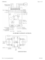
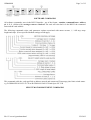
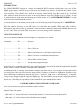
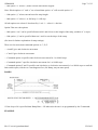
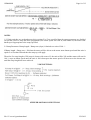
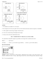
GSM4MAN
Page 1 of 12
GSM4 USER MANUAL
ISSUE 4.0 JAN 2000
PRODUCT OVERVIEW
The GSM4, together with the optional PSU4 power supply, provides a comprehensive facility for controlling 4
or 8 wire Bipolar driven stepper motors. Up to 4 GSM4 cards can be daisy-chained to control up to 4 motors.
Simple software commands can be sent from a PC via the RS232 serial port to the GSM4 to control motor
direction, number of steps, start and stop ramp length and slope, motor current and ½ / full step. All commands
carry address information.
On board settings include card address (0, 1, 2, 3) motor current (set to suit motor specification) and number of
steps / second (speed).
SPECIFICATION
MOTOR DRIVE: 4 or 8 wire bipolar current switching, up to 1.5 ampere / phase Voltage 12 to 40 Volts DC
(maximum).
INTERFACE: RS232C 9600 Baud, DTE via 9 pin “D” connector, Tx, Rx & GND active (Null modem) daisychained from card to card.
ADDRESS: On board card address selection 0, 1, 2, 3. Software commands include card address.
MOTOR CONTROL: Current, speed, direction, ½ current, boost, ½ / full step, number of steps (0-99999),
ramp (length and slope), limit and enable switch provision.
BOARD LAYOUT
file://C:\www1\gsm4man.html
25/03/02
GSM4MAN
Page 2 of 12
MOTOR DRIVE SCHEMATIC (ONE PHASE)
SWITCH SETTINGS
file://C:\www1\gsm4man.html
25/03/02
GSM4MAN
Page 3 of 12
SOFTWARE COMMANDS
All software commands, sent via the RS232 interface , are of the format - number, command letter, address
(0, 1, 2, 3, ) followed by carriage return or linefeed. The card will echo back via the RS232 the command
letter and the card address.
The following commands select card parameter options associated with motor current, ½ / full step, ramp
length and slope. (If not specified default settings would apply.
This command polls the card specified at address entered and returns an ID message plus limit switch status.
e.g. B GSM4 999 JAN 95 L/F C/R or B GSM4 999 JAN 95 Limit Open L/F C/R
SELECT MOTOR MOVEMENT COMMANDS
file://C:\www1\gsm4man.html
25/03/02
GSM4MAN
Page 4 of 12
PROGRAMMABLE MOTOR SPEED CONTROL
GSM4TERM>EXE Software Control of Motor Speed
When the programme GSM4TERM is run, or GSM4TERM TESTMODE, the motor speed selection column is
shown to the right of the screen. The up/down cursor keys are used to select the required motor speed. The ->
point to the selected speed. The speed selected will apply for all other commands until another speed is
selected.
The “Variable” option is the speed selected by the pot 1 setting.
GSM4 - ON BOARD SETTINGS
POT 1. Pot 1 adjusts the speed of the motor in steps / second. This pot should only be adjusted as required
during the setting up stage of the process to give the required motor speed.
POT 2. Pot 2 is adjusted to provide the required winding current for the motor. It is advisable to start with the
pot at minimum (fully clockwise) and increase slowly until motor current is sufficient to drive the motor. To
adjust the current connect a voltmeter across either OR33 resister. Set meter to 2 Volts F.S.D. or nearest range.
Adjust POT 2 for required reading of voltmeter where 1mV = 3 mA winding current.
MOTOR CURRENT ADJUSTMENT
file://C:\www1\gsm4man.html
25/03/02
GSM4MAN
Page 5 of 12
For example if the motor winding recommended current is 1.5 Ampere then the pot 2 should be adjusted to read
500mV. Warning ! Under no circumstances connect a meter set to Ohms Range, or any other voltage source,
across R ref., as this will destroy the motor drive controller. Limit and motor enable switches may be connected
to the GSM4. If the motor enable switch is NOT used the appropriate terminal on the GSM4 must be linked to
OV logic.
SERIAL PORT SETUP (COM 1)
9600 Baud
8 Bits
No Parity
1 Stop Bit
DEFAULT SETTINGS
On power up the GSM4 sets to the following default settings.
Full step mode. - 100% motor current option OFF.
No Ramp. - Motor current ON when stopped. Current boost for ramp OFF.
WARNINGS AND SAFETY INFORMATION
1/. Stepper motors get very HOT!
2/. Ensure motors are not over driven! Refer to motor specification.
3/. Ensure the GSM4 and PSU4 are well ventilated.
4/. DO NOT disable the GSM4 fan.
5/. DO NOT connect or disconnect the motor with power supplied to the GSM4
6/. Stepper motors generate high “Back EMF” voltages. Allow time for the magnetic fields to decay before
disconnecting motors.
7/. The MAXIMUM motor drive voltage is 40 V. DO NOT exceed 40 VOLTS.
8/. Ensure the mains input is adequately fused. The recommended mains input fuse rating is 250mA Slow
Blow.
9/. The GSM4 and stepper motors generate RF frequencies, appropriate screening is recommended.
10/. DO NOT connect a meter set to Ohms Range to the Reference resistors.
USING CONTROL PROGRAMME
file://C:\www1\gsm4man.html
25/03/02
GSM4MAN
Page 6 of 12
INTRODUCTION
The GSM4TERM.EXE program is a simple self contained RS232 controller which allows new users of the
GSM4 stepper motor controller to get a system up and running very quickly. It offers all the features of the
GSM4 to the user by assigning the various commands to function keys and asking for the required parameters
where necessary. The software can be used in two modes. Normal mode allows the control of up to 4 GSM4
units, while test mode allows the software to be used without the need for a GSM4 unit to be present. To run
the software in test mode, enter the following at the DOS prompt : C:\> GSM4TERM TESTMODE. Use this
mode to become familiar with the software.
To run the software in the normal control mode, enter the following at the DOS prompt : C:\> GSM4TERM .
When the software first runs, it sends ID requests to each of the four possible GSM4 units which could be
connected. If any respond, this is noted and a status message is printed showing which GSM4 addresses are
active. The last GSM4 which responded, becomes the default one. To select a different GSM4, use the number
keys 0,1,2 & 3. If the requested GSM4 is not active, an error message will be displayed.
USING THE SOFTWARE
Each of the GSM4 commands has been assigned to a function key as follows:
Command .................Key ...................Purpose
A ...............................F1 ....................Move Anti-clockwise
C............................... F2 ....................Move Clockwise
E................................ F3 ....................Move Anti-clockwise or until limit switch operates
G................................F4 .....................Move Clockwise or until limit switch operates
D ...............................F5 .....................Set-up Motor control options
F ................................F6 .....................Set-up Ramp length and slope
Each of the above commands will ask for any required parameters and will wait until the command has finished
and the GSM4 is ready for another command before continuing.
An additional mode is included in the software in which the motor can be driven using the left and right cursor
keys and displays the total offset from the start position. Each press of the left or right cursor keys moves the
motor 10000 steps in the chosen direction (left cursor = clockwise, right cursor = anti-clockwise). The number
of steps can be changed using the PgUp and PgDn keys. The total number of steps moved is displayed with the
direction. It also allows the motor to be automatically moved back to the “zero” reference point. This is a
simple way of checking the repeatability of the mechanical system attached to the motor.
UNDERSTANDING THE SOFTWARE COMMANDS
There are two motor drive option commands, options D and F.
Option D has 5 sub-options:
.....Sub-option “u” selects 100% motor current when running. (If not selected motor runs at 66%).
.....Sub-option “w” selects motor current Off when motor stopped.
file://C:\www1\gsm4man.html
25/03/02
GSM4MAN
Page 7 of 12
.....Sub-option “x” selects ½ motor current when motor stopped.
Note: If both options “w” and “x” are selected then option “w” will override option “x”.
.....Sub-option “y” selects current boost for ramp length.
.....Sub-option “z” selects ½ or full step. 0 = full step.
All sub-options are selected / deselected by 1 or 0. 1 = select 0 = deselect.
Option F has two sub-options:
.....Sub-option “xxx” can be specified between 001 and 999 to set the length of the ramp, (number of ½ steps)
.....Sub option “y” can be specified between 1 and 9 to set the slope of the ramp.
(See later for further explanation of ramp settings).
There are four movement command options A, C, E, G.
.....A and E give anti-clockwise movement.
.....C and G give clockwise movement.
.....Command option A specifies anti-clockwise movement for 1 to 99999 steps.
.....Command option C specifies clockwise movement for 1 to 99999 steps
.....Command options E and G specifies anti-clockwise or clockwise movement for 1 to 99999 steps or until the
limit switch opens, which ever event happens first. (No Ramp, stays at start speed).
RAMPS
* If the slope of 0 is specified then Ramp Rate = 256 otherwise the rate is as programmed by the F command.
EXAMPLE
file://C:\www1\gsm4man.html
25/03/02
GSM4MAN
Page 8 of 12
NOTES
1/. If limit switches are used and motor drive options E or F are specified then the ramp parameters are disabled
except that, where a ramp has been programmed, the motor speed will start at, and remain at, the motor start
datum speed appropriate to the ramp specified.
2/. Ramp Parameter. Ramp length ÷ Ramp rate (slope) is limited to a ratio of 200 : 1
If Ramp length ÷ Ramp rate > 200 then the motor will be driven at the motor start datum speed until the ratio is
equal to or less than 200 and then the ramp up will apply.
Therefore if a ramp length of 500 steps is chosen with a rate of 2 the ratio will be 250 and the motor will run for
100 ½ steps at datum speed until the ratio is 200 whereupon the motor speed will increase at the chosen rate
until the ramp length has been achieved.
V REF SETTINGS
STEPPER MOTOR CONNECTIONS
file://C:\www1\gsm4man.html
25/03/02
GSM4MAN
Page 9 of 12
NOTES:
1/. The GSM4 is not suitable for 5 wire motors.
2/. Reversing the wires of any one phase will reverse the direction the motor rotates in response to commands.
3/. 8 Wire parallel connections give higher rotational speed.
4/. 8 wire series connections provide higher motor torque.
5/. Always refer to the motor manufacturers data.
PSU4 - POWER SUPPLY CARD (For use with the GSM4)
Two transformer isolated DC outputs are provided, one for logic and a second for motor drive.
INPUT .................240 Volt AC
OUTPUT .............250 mA., @ 12 Volt DC (Logic and Fan).........800 mA., @ 34 Volt DC (Motor)
BLOCK DIAGRAM
NOTES For pinout / connections see block diagram. Although the motor supply is only rated at 800 mA., this
should be sufficient for most 1.5 Amp. / phase stepper motors. Fuse, short circuit protection, and mains voltage
file://C:\www1\gsm4man.html
25/03/02
GSM4MAN
Page 10 of 12
shielding is left to the customer to implement.
GENERAL NOTES
1/. The stepper motor chosen for use with the GSM4 must be fully compatible with Bipolar drivers.
2/. Motor torque is motor current and motor speed related. Torque is proportional to current and inversely
proportional to speed.
3/. The effective motor impedance is proportional to the load and the speed of the motor.
4/. The GSM4 will supply sufficient current for motors specified at 1.5 Amp / winding. Motors with higher
current requirements can be driven but they will not run at full power.
5/. If motor enable switch is not used the appropriate connector must be linked to 0 Volt Logic.
6/. Ramps are used to provide increased starting torque and to overcome motor resonance.
7/. Current boost is dependent upon the setting of Pot 2 and is available for the length of the ramp only.
8/. When adjusting Pot 2 it is recommended that the initial winding current is set at less than the value
recommended for the motor and that the motor is driven at this current whilst the motor temperature is
monitored. Avoid running the motor at high temperatures. (See motor manufacturers specification).
9/. Stepper motor drivers generate large amounts of RFI and should be enclosed in an adequately screened
enclosure, having good ventilation.
10/. The GSM4 must be connected to a serial port in order to control the GSM4 and motor.
11/. Pins 4 & 6, 7 & 8 on the serial port to the PC are linked on the PCB to terminate handshakes
Application Notes for GSM4 Series Stepper Motor Controller.
Programming Advice
The following notes are intended to serve as a starting point in showing the possible options for controlling
stepper motors using the Greenwich Instruments range of GSM4 Driver Cards.
What Is The Purpose Of The GsmTerm Program Supplied With The Card?
The GSM4 Controller is supplied with a software driver disk. The Disk contains a very simple DOS based
program that can be used to test that your motor and controller are set up correctly. Using the software it is
possible to test simple movements and functions of the motor configuration. It's main use is to allow you to
verify that the the motor and card have been set up and wired correctly.
Using The ASCII Commands
It is most likely however that you will require a much greater control over the stepper motor. In which case you
can use the ASCII text commands listed under the section SOFTWARE COMMANDS in the GSM4 Operating
Manual.
The Serial Port must have it's parameters set to 9600 Baud, 8 Data Bits, No Parity, and no hardware or software
handshaking.
All commands are sent as plain ASCII text through the appropriate Serial Port. For testing it is possible to use
file://C:\www1\gsm4man.html
25/03/02
GSM4MAN
Page 11 of 12
any terminal type program with the serial port configured as described above. (e.g. Hyper Terminal as supplied
with Windows 95/98).
The following characters show an example of how to move the motor anti-clockwise 200 steps on a card set to
address 0 :- 200A0<CR>
(*<CR> being a carriage return).
Upon receiving the command the card will echo back the command letter and the drive address, which in this
case would be :- A0
This forms the basis upon which sequences of commands can be put together.
How Do I Create A Sequence Of Motor Movements?
There are a number of ways in which sequences of commands can be created. The method you decide to use is
basically down to your relevant programming experience and the tools you have available to you.
1) Terminal Programs
Many "Terminal" programs have the facility to allow "Scripts" to be written. Therefore it is normally possible
to use the Scripting Language to create sequences of commands. Normally scripts can be used to create loops,
delays between successive commands, and decisions dependant upon the controller responses.
2) DOS using BASIC
QBASIC or QuickBasic are two DOS based development tools that are relatively straight forward to use.
QBasic was supplied as part of MSDOS versions 5 and 6.xx. The on-line help pages provide examples of how
to open the serial port, and how to send and receive ASCII data through the port. The commands associated
with setting up the serial port and sending data to it are:- OPEN COM, COM, PRINT, GET & PUT. Once a
serial port has been successfully opened it is possible use the PRINT command to send strings of text (e.g.
200A0) through the port.
3) Control under Windows
Control under Windows can be achieved using any development tools that allows access to the Serial port.
Visual Basic, Visual C++, Borland Delphi & C++ Builder are all popular programming languages that can be
used to control the motor.
Windows does not allow you to send data to the directly as with DOS, instead you need to communicate to the
serial port through a serial port driver. Visual Basic & C++ ship with a control called MSCOMM32 which can
be used for this purpose. If the programming language does not come with a driver is normally possible to use a
third party serial port driver.
The programming pages of the Internet provide a rich source of information and freeware & commercial
drivers. www.marshallsoft.com provides a good shareware driver with excellent documentation and examples
on using the driver with Windows 3.11 95/98/NT. Look at the example file Simple for a quick guide to setting
up and using the serial port.
4) Other Languages
Basically it is possible to control the Stepper Motor Card from any software that can access the serial port. The
device used to control the motor is not limited to being a PC, it can be any device that has a serial port that can
be configured as described above.
How Do I Know When A Command Has Finished Executing?
file://C:\www1\gsm4man.html
25/03/02
GSM4MAN
Page 12 of 12
When a command is sent to the GSM4, the card immediately responds by echoing back to the PC with the
command letter and drive address. The GSM4 will then ignore any further commands being sent until it has
completed the previous task. i.e. any commands that are transmitted to the GSM4 whilst the GSM4 is currently
executing will not receive an echo back to indicate the the command has been successfully received by the
GSM4.
Therefore to guarantee that all commands in the sequence are executed in turn, each command that is sent must
receive an acknowledgment back from the GSM4 before moving onto the next command. One such way of
doing this is to wait for a valid response after each command is sent. If the response is not received, it can be
assumed that the card was still busy when the command was sent, in which case the command will need to be
resent.
Alternatively it is possible to use the "B" command to Poll the card to see if it is busy. In this case the card will
again ignore all the "B" commands until the it is free to respond with the ID message plus the limit switch
status, which signals that the motor has finished the previous command.
PDF PRINTOUT
file://C:\www1\gsm4man.html
25/03/02