1
External Serial PC Watchdog
User’s Manual
Berkshire Products, Inc.
Phone:
770-271-0088
http://www.berkprod.com/
Rev: 1.21
© Copyright 1999 - 2009
PC Watchdog is a registered trademark of Berkshire Products
Table of Contents
1. INTRODUCTION............................................................................................................................................1
2. OPERATION...................................................................................................................................................2
3. INSTALLATION OF SUPPLIED COMPONENTS....................................................................................3
3.1 BASIC INSTALLATION.............................................................................................................................................3
3.2 PC RESET CABLE INSTALLATION...........................................................................................................................4
3.3 EXTERNAL POWER MODULE INSTALLATION............................................................................................................4
4. DIP SWITCH SETTINGS.............................................................................................................................5
4.1 MODE SWITCHES - SW1, SW2 & SW3..............................................................................................................5
4.1.1 MONITOR MODE - SW1.....................................................................................................................................5
4.1.2 COMMAND MODE - SW2....................................................................................................................................5
4.1.3 RING MODE - SW3............................................................................................................................................6
4.2 POWER ON DELAY (POD) - SW4.......................................................................................................................6
4.3 UNUSED - SW5....................................................................................................................................................6
4.4 TIMEOUT COUNT / RING COUNT - SW6, SW7, & SW8.......................................................................................7
5. COMMAND MODE OPERATION..............................................................................................................8
5.1 COM PORT SETTINGS.........................................................................................................................................8
5.2 COMMAND FORMAT..............................................................................................................................................8
5.3 RESPONSE FORMAT...............................................................................................................................................9
5.4 WATCHDOG COMMANDS......................................................................................................................................10
5.4.1 RESET PC NOW - [0X20].................................................................................................................................10
5.4.2 RESET PC IN 10 SECONDS - [0X21]...................................................................................................................10
5.4.3 OVERRIDE POWER-ON-DELAY - [0X24]..............................................................................................................11
5.4.4 DISABLE WATCHDOG - [0X28]...........................................................................................................................11
5.4.5 ENABLE WATCHDOG - [0X29]............................................................................................................................11
5.4.6 FIRMWARE MAJOR REV - [0X30].......................................................................................................................11
5.4.7 FIRMWARE MINOR REV - [0X31].......................................................................................................................12
5.4.8 NO OPERATION - [0X34]...................................................................................................................................12
5.4.9 GET RESET COUNT - [0X38].............................................................................................................................12
5.4.10 CLEAR RESET COUNT & LED - [0X39]...........................................................................................................12
5.4.11 TURN OFF AC POWER MODULE - [0X40].........................................................................................................12
5.4.12 TURN ON AC POWER MODULE - [0X41]..........................................................................................................13
5.4.13 DIAGNOSTIC COMMANDS - [0XC0-0XFF]..........................................................................................................14
6. LED OPERATION ......................................................................................................................................15
6.1 TOP LED..........................................................................................................................................................15
6.2 BOTTOM LED...................................................................................................................................................15
7. GETTING PAST THE LOGIN ON WIN95/98..........................................................................................16
8. WATCHDOG PROGRAMS........................................................................................................................17
8.1
8.2
8.3
8.4
WATCHDOG TEST PROGRAM - DOS - WIN 3.XX..................................................................................................17
WATCHDOG TEST PROGRAM - WINDOWS 95, 98, ME, NT, & 2000....................................................................17
VB4 TEST & TSR PROGRAM - WINDOWS 95, 98 , ME, NT, & 2000...............................................................18
VB6 TEST & TSR PROGRAM - WINDOWS 95, 98 , ME, NT, & 2000...............................................................18
9. APPENDIX A - SPECIFICATIONS...........................................................................................................19
10. APPENDIX B - WARRANTY...................................................................................................................20
11. APPENDIX C - SERVICE AND TECH SUPPORT................................................................................21
11.1 CALLING TECH SUPPORT...................................................................................................................................21
11.2 PRODUCT RETURNS...........................................................................................................................................21
12. APPENDIX D - AGENCY APPROVALS.................................................................................................22
12.1 FCC - CLASS A..............................................................................................................................................22
12.2 CE .................................................................................................................................................................22
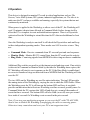
1.Introduction
The Serial Watchdog is an external device that is used to monitor a PC in order to
ensure maximum system availability. It has the following features:
• Acts as a pass-through serial port with standard PC DB-9 connectors.
• Monitors the PC serial port for control line activity from the PC itself.
• Monitors the Ring Indicator (RI) from a MODEM on the serial port for excessive
rings without an answer.
• Can be used right from the box without any support programs.
• Also has a Command Mode that allows a user program to exert additional control
over the Watchdog.
• Two externally visible LEDs show status of Watchdog.
• Watchdog has I/O port to control an external power module to cycle AC power on a
PC and/or external device.
• Programmable power-on delay to allow the PC to complete its initialization
sequence.
1
2.Operation
This device is designed to monitor PCs used in critical applications such as: File
Servers, Voice Mail Systems, ISP systems, industrial applications, etc. The idea is to
make sure the PC is always available and running; especially for systems that are not
continuously monitored.
When power is applied to the Watchdog, or after a reset of the PC, the Watchdog will
wait 2.5 minutes (shorter times allowed in Command Mode) before it arms itself to
allow the PC to complete its reset and initialization sequence. There is a Dip switch
option to allow the Watchdog to extend this time for PCs that need additional re-boot
time.
Once the Watchdog is ready to arm itself it will check the Dip switches and enable up
to three independent operating modes. These modes can ALL be active at once. They
are:
• Command Mode - Receive commands from PC on serial port and send responses.
• Monitor Mode - Monitor RS-232 control lines from the PC serial port for activity.
• Ring Mode - Count ring signals from MODEM to detect ring-no-answer conditions.
Additional Dip switches are used to set the timeout period and ring count. If no activity
is detected in Command or Monitor Mode by the time the Watchdog timer expires, the
PC Watchdog will start its reset sequence on the PC. If the Ring Mode is enabled and
an excessive number of rings are detected from a MODEM then the Watchdog will also
reset the PC.
The two LEDs on the Watchdog are used for status indication. The top LED provides
the arming status of the Watchdog by varying the rate at which the LED flashes. When
the Watchdog resets the PC it will turn on the bottom LED and leave it on which
provides an indication that at least one Watchdog reset has occurred, possibly more. In
Command Mode the PC can turn this LED off and also get a count of the number of
resets that have occurred. The bottom LED will also flash (on or off) once per second
for a tenth of a second if a Watchdog event occurred in the prior second.
Note: If you stop your application program or you reset the PC with CTL-ALT-DEL,
then be sure to disable the Watchdog by unplugging the cable or removing power.
Otherwise it may count down and reset your PC at an inopportune time!
2
3. Installation of Supplied Components
The standard Watchdog package contains the following items:
• A CD
• The Watchdog timer.
• An AC/DC adapter – for North American customers only. See section 3.1 for specs
on the power adapter.
• A DB-9 to DB-9 serial cable.
If you did not order a Power Module then you will get:
• A three conductor cable with 1/8" stereo plugs on each end.
• A PC I/O bracket with a 1/8" stereo jack and two headers on a small circuit board.
• A reset cable
If you ordered a Power Module it will come with an RJ-11 cable to plug into the
watchdog. The 230VAC Power module also comes with a power cable.
3.1 Basic Installation
Perform these steps to install the Watchdog:
• Plug the AC/DC adapter into a 120VAC wall outlet. If you lose this adapter, it can
be replaced with a AC/DC type that puts out 9-16V DC at 100mA minimum. It also
must have a 2.1mm jack with the center pin positive.
• Make sure the Dip switches are set properly before applying power to the Watchdog
since it only checks the switches at power up and after each reset of the PC.
• Plug the AC adapter into the 2.1mm Power jack on the Watchdog. The top LED on
the Watchdog should start flashing at a 1 second rate.
• Connect the DB-9S end of the cable to the serial COM port on the PC. Connect the
other end of the cable (DB-9P) to the Serial Input port on the Watchdog.
• Optional Step. If you are using the pass through mode of the Watchdog then connect
your original serial device to the Serial Output port on the Watchdog.
3
3.2 PC Reset Cable installation
These steps are required to allow the Watchdog to reset the PC. They are not required if
you purchased the optional external power module and do not want to reset the PC.
• Open the PC and install the PC I/O bracket in an unused slot on the PC. Remove
your existing reset cable and plug it onto one the two headers on the small circuit
board - either one is OK. Plug the enclosed reset cable on the other header on the I/
O bracket and to the original reset header on the PC.
• Connect the three conductor stereo cable from the Reset Out port on the Watchdog
to the 1/8" jack on the PC I/O bracket.
3.3 External Power Module Installation
If you purchased the external power module then perform the following:
• Plug the power module into an AC outlet. Plug the PC or other devices into the
power module outlet. If you plug an outlet strip into the power module then: 1. Do
not exceed the 10 Amp rating of the module. 2. Do not plug the Watchdog's AC/DC
adapter into the strip.
• If you are using the 220 VAC module then connect the supplied power cable from
the module to the IEC power jack on the PC. Connect to original PC power cable to
the input of the power module.
• Plug the enclosed RJ-11 (telephone) cable into the AC Power Module jack on the
Watchdog and the other end to the jack on the side of the power module.
4
4. Dip Switch Settings
All the switches are read at power up and after each time that the Watchdog resets the
PC. A switch that is DOWN is ON and a switch that is UP is OFF. The following
sections cover the switch options.
4.1 Mode Switches - SW1, SW2 & SW3
These three switches set the operating mode of the Watchdog. If all three of these
switches are off then the Watchdog powers up in factory diagnostics mode and will not
operate properly!
It is OK for one or more of these switches to be on at one time. The Watchdog will
support multiple modes together.
4.1.1 Monitor Mode - SW1
When this mode is active the Watchdog will monitor the three output control lines on
the serial COM port of the PC. The lines are:
• Transmit Data (TxD) on Pin 3 of the DB-9.
• Data Terminal Ready (DTR) on Pin 4 of the DB-9.
• Request To Send (RTS) on Pin 7 of the DB-9.
Any activity on any of these lines will cause the Watchdog to reset its timeout count.
4.1.2 Command Mode - SW2
If this switch is on the Watchdog enters command mode. This requires that the PC send
commands to the Watchdog as serial data to make it reset the timeout counter. See the
Command Mode section for further information. This mode will require the user to
write support software into their application program.
5
4.1.3 Ring Mode - SW3
If this switch is on the Watchdog will count pulses on the Ring Indicator (RI) pin 9 of
the cable from the MODEM. If the number of rings exceed a preset number (set by
switches 6-8) then the Watchdog will reset the PC. If the number of rings is lower,
followed by an idle time of about 15 seconds, then the Watchdog will reset the ring
counter based on the settings of switches 6-8.
If this is the only switch of three that is on then the Watchdog will not use the timeout
mode at all. It will only function as a ring-no-answer Watchdog.
4.2 Power On Delay (POD) - SW4
After a power up or a PC reset the Watchdog normally waits 2.5 minutes to allow the
PC to re-boot. This time can be shortened in Command Mode. Sometimes the PC will
require more than 2.5 minutes to complete the re-boot, which can be accommodated by
turning on this switch.
In Monitor or Command Mode the Watchdog will delay starting the timeout counter
until it "sees" the first activity in either of these modes. In the Ring mode it will wait
until the DTR line to MODEM goes active. When DTR goes active the bottom LED
will flash once.
Note: If the PC does not complete the re-boot process correctly, then this option can
disable the Watchdog as well as leave the PC frozen.
4.3 Unused - SW5
This switch is not used at this point. It is reserved for custom versions of the Watchdog.
6
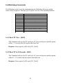
4.4 Timeout Count / Ring Count - SW6, SW7, & SW8
These switches set the delay time until the Watchdog resets the PC. As long as the
Watchdog is getting activity in Command or Monitor Mode then it will reset the
timeout counter with these values. These switches also set the ring counts in Ring
Mode for ring-no-answer detection. The settings and times are:
Switches 6-8
OFF-OFF-OFF
OFF-OFF- ON
OFF- ON-OFF
OFF- ON- ON
ON-OFF-OFF
ON-OFF- ON
ON- ON-OFF
ON- ON- ON
Delay Time
5 Seconds
10 Seconds
30 Seconds
1 Minute
10 Minutes
30 Minutes
1 Hour
2 Hour
.
7
Ring Count
2
3
5
9
9
9
9
9
5. Command Mode Operation
The Watchdog is designed to monitor the Transmit Data (TxD) line from the PC and
respond to commands from the PC when the Command Mode is enabled. The
Watchdog is wire-ORed into the receive data line from an external device such as a
MODEM to allow it to send back responses. In a lot of cases the PC may be able to
communicate with a MODEM by activating Data Terminal Ready (DTR) and using
standard AT commands. The PC should be able to communicate with the Watchdog by
dropping DTR and sending commands to the Watchdog. The MODEM should ignore
the Watchdog data since DTR is inactive and the Watchdog commands do not start
with the AT sequence.
5.1 COM Port Settings
The Watchdog requires that the COM port on the PC be set to 1200 Baud, 8 Data Bits,
No Parity Bit, and 2 Stop Bits. The requirement for 2 stop bits is important because the
processor uses the idle time between characters to process input data and it takes care of
other processing tasks.
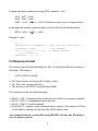
5.2 Command Format
The Watchdog looks for a five (5) byte command packet that includes a checksum. This
is done to help insure that MODEM data is not accidentally interpreted as commands.
The format is:
[0x01] [0x57] [0x84] [cc] [ss]
• The first three bytes are always the fixed hex values.
• cc - This is the actual command byte described later.
• ss - This is the simple checksum. It is calculated by adding the prior 4 bytes and
subtracting the value from 0x00. When the Watchdog receives the data and sums all
5 bytes it should get the byte (unsigned char) result 0x00.
8
Example checksum computation using NOP command – 0x34:
0x01 + 0x57 = 0x58
0x58 + 0x84 = 0xDC
0xDC + 0x34 = 0x110 => 0x10 (Checksum is only a byte or unsigned char)
at this point the number required to add to 0x10 is 0xF0 for the checksum byte.
0X10 + 0xF0 = 0x100 => 0x00
Example C code:
int i ;
unsigned char b, strTxBuff[5] = {0x01, 'W', 0x84, 0x00, 0x00} ;
strTxBuff[3] = 0x34 ;
for(i = 0, b = 0; i < 4; i++)
b += strTxBuff[i] ;
strTxBuff[4] = (0 - b) ;
// nop command
// compute checksum
5.3 Response Format
The response data from the Watchdog is a four (4) byte packet that does not have a
checksum. The format is:
[0x57] [0x84] [rr] [0x0d]
• The first two bytes are always the fixed hex values.
• rr - This is the response data byte.
• The last byte is an ASCII Carriage Return [0x0d].
The responses can be one of the following:
•
•
•
•
[0x06] - ACK - Command received and processed OK but no response required.
[0x15] - NAK1 - Command had checksum error.
[0x16] - NAK2 - Invalid command.
[0x20-0xFF] - responses from commands where required. All responses will have
0x20 added so that they do not look like ASCII control codes.
Any commands that are received OK (except RESET) will cause the Watchdog to
reset the timeout counter.
9
5.4 Watchdog Commands
The following sections cover the commands that the Watchdog will accept and the
return values if required. This table gives a quick overview of the command numbers.
Command
0x20
0x21
0x24
0x28
0x29
0x30
0x31
0x34
0x38
0x39
0x40
0x41
Description
Reset PC Now
Reset PC in 10 Seconds
Arm Watchdog Now
Disable Watchdog
Enable Watchdog
Firmware Major Rev
Firmware Minor Rev
No Operation
Get Reset Count
Clear Reset Count & LED
Turn Off AC Power Module
Turn On AC Power Module
5.4.1 Reset PC Now - [0x20]
This Command will reset the PC (and cycle AC power with power module option)
within 1 - 2 seconds after the response has been sent.
Response: None required, will be an ACK - [0x06].
5.4.2 Reset PC in 10 Seconds - [0x21]
This Command will reset the PC (and cycle AC power with power module option)
within 10 - 12 seconds after the response has been sent.
Response: None required, will be an ACK - [0x06].
10
5.4.3 Override Power-On-Delay - [0x24]
This Command will make the Watchdog terminate the 2.5-minute power on delay
and arm itself after a power up or PC reset. If the Power-on-Delay Dip switch is
set (switch number 4) then you will still need to send at least one command (such
as No Operation – 0x34) in order to arm the board. Do not send this command
more than one time!
Response: 0x20 - command processed OK.
0x21 - Watchdog was already armed - command ignored.
5.4.4 Disable Watchdog - [0x28]
This Command will disable the Watchdog. USE IT CAREFULLY!
Response: None required, will be an ACK - [0x06].
5.4.5 Enable Watchdog - [0x29]
This Command will enable the Watchdog.
Response: None required, will be an ACK - [0x06].
5.4.6 Firmware Major Rev - [0x30]
This Command returns the major revision of the firmware.
Response: A value from 0x20 - 0x29. Subtract 0x20 to get the value in hex.
Ex: 0x22 - 0x20 = 2 -> Rev 2.xx
11
5.4.7 Firmware Minor Rev - [0x31]
This Command returns the minor revision of the firmware.
Response: A value from 0x20 - 0x83. Subtract 0x20 to get the value in hex.
Ex: 0x43 - 0x20 = 0x23 = 35 -> Rev x.35
5.4.8 No Operation - [0x34]
This Command is only used to reset the timeout counter.
Response: None required, will be an ACK - [0x06].
5.4.9 Get Reset Count - [0x38]
This Command returns the number of times the Watchdog has reset the PC. The
counter stops at 128 (0x80).
Response: A value from 0x20 - 0xA0. Subtract 0x20 to get the value in hex.
5.4.10 Clear Reset Count & LED - [0x39]
This Command clears the reset counter back to zero and turns off the bottom LED.
Response: None required, will be an ACK – [0x06].
5.4.11 Turn Off AC Power Module - [0x40]
This Command turns off the optional AC power module if installed.
Response: None required, will be an ACK - [0x06].
12
5.4.12 Turn On AC Power Module - [0x41]
This Command turns off the optional AC power module if installed.
Response: None required, will be an ACK - [0x06].
13
5.4.13 Diagnostic Commands - [0xC0-0xFF]
Commands in this range are reserved for diagnostic production tests. They may
produce undesirable results.
14
6. LED Operation
The two LEDs on the Watchdog are used for system status.
6.1 Top LED
During the 2.5 minutes that the Watchdog waits after power-up or after it resets the PC
it will flash this LED at a 1 second rate (1 second on, 1 second off). Once the Watchdog
has armed itself it will flash the LED at a 350mS rate. In the last 3 seconds before the
Watchdog resets the PC it will flash this LED rapidly at a 100mS rate.
6.2 Bottom LED
After the first time the Watchdog resets the PC it will light this LED as a visible
indicator that at least one reset (maybe more) has occurred. This LED can be turned off
by cycling power on the Watchdog or via Command Mode.
This LED will also flash once per second for 100mS to indicate that activity has been
detected in Command or Monitor Mode and for each ring pulse from the MODEM in
Ring Mode. This flash will be the inverse of the LED state at the time.
15
7. Getting past the Login on Win95/98
When Windows boots it will stop with a login screen that prompts for a user name and
password. It will hang at this point indefinitely until the data is entered or you click the
Cancel button. If the Watchdog has rebooted your PC then it would hang at this point.
Microsoft has solved this problem with a set of utilities called Powertoys that can be
downloaded from their site at: http://www.microsoft.com/. One of the utilities in the
package is called TWEAKUI that installs in the Control Panel under My Computer.
When you run the utility there will be a tab called Network that allows you to specify
an auto login and provide the computer name and password.
The file is called W95powertoy.exe. Microsoft claims that it is designed for Win95 and
NT but not for Win 98. While we can't endorse operation under Win 98, we do know of
users (including ourselves) who are using the TWEAKUI utility without problems on
Win 98.
16
8. Watchdog Programs
There are some programs on the enclosed diskette for testing and configuring the
Watchdog board. Some of these programs use switches to determine which user port to
check to get status or perform commands. All the source and other support files are
supplied for each program which should make it easier to modify them for user's special
requirements. Check the diskette for other programs that have been added since this
manual was written.
8.1 Watchdog Test Program - DOS - Win 3.xx
This program is used to test and configure the Serial Watchdog under DOS or Win
3.xx. The name of this program is: WD-TEST.EXE and it is in the \TestPgm directory
on the diskette.
When this program runs it will prompt the user for a command to send the Watchdog
and then display the response. You must have the Command DIP switch turned on for
this option to work.
The switch for this program is:
/p# - Where # = 1-4 for COM1-4 (default is COM1)
EX: C:>wd-test /p2
8.2 Watchdog Test Program - Windows 95, 98, ME, NT, & 2000
This program is used to test and configure the Serial Watchdog. This program is a
console application written in 32 bit code. It will only run under WIN95, 98, and NT.
The name of this program is: W32ConApp.exe and it is in the \ W32ConApp directory
on the diskette.
When this program runs it will prompt the user for a command to send the Watchdog
and then display the response. You must have the Command DIP switch turned on for
this option to work.
17
The switch for this program is:
/p# - Where # = 1-4 for COM1-4 (default is COM1)
EX: C:>w32conapp /p2
8.3 VB4 Test & TSR Program - Windows 95, 98 , ME, NT, & 2000
This program and files are in the VB4_Pgm directory on the diskette. The program
requires the VB40032.DLL and MSCOMM32.OCX files to work. You can leave these
files in the same directory or move them to the system directory.
When this program runs it will allow you to choose the serial port and test the
Watchdog by sending a revision command to display the firmware version. You can
also select RUN that will minimize the program and make it toggle DTR to keep the
Watchdog from resetting the PC. The Watchdog must be in monitor mode.
You can also put this program into a startup group with two command line switches
that must be present. The switches for this program are:
/p# - Where # = 1-4 for COM1-4 (default is COM1)
/m - start minimized
EX: Ser-WDog /p2 /m
8.4 VB6 Test & TSR Program - Windows 95, 98 , ME, NT, & 2000
This program and files are in the VB6_Pgm directory on the diskette. Works the same
as and uses the same command line switches as the VB4 version.
18
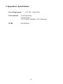
9. Appendix A - Specifications
Power Requirements:
+9-16 VDC - 200mA Max.
Environmental:
-20-65° Operating
-20-70° Storage
5-95% Relative Humidity - Non Condensing
MTBF:
500,000 Hours
19
10. Appendix B - Warranty
Berkshire Products, Inc. warrants to the original consumer or other end user purchaser
that this product is free from defects in materials or workmanship for a period of one
(1) year from the date of purchase. During the warranty period, and upon proof of
purchase, the product will be repaired or replaced (with the same or functionally
equivalent model) at our option, without charge for either parts or labor.
This warranty does not apply to defects due directly or indirectly to misuse, abuse,
negligence, accident, repairs or alterations made by the customer or another party.
UNDER NO CIRCUMSTANCES WILL BERKSHIRE PRODUCTS, Inc. BE LIABLE
IN ANY WAY TO ANY PURCHASER FOR DAMAGES, LOST REVENUE, LOST
WAGES, OR ANY OTHER INCIDENTAL OR CONSEQUENTIAL DAMAGES
ARISING OUT OF THE USE OR INABILITY TO USE THIS PRODUCT.
Berkshire Products, Inc. reserves the right to make modifications in this product
without prior notification.
20
11. Appendix C - Service and Tech Support
We are available to help you with your questions and problems that you may have with
our product. Our technical support is available:
Monday through Friday (except holidays)
8:30 AM to 5:00 PM (Eastern Time)
770-271-0088
Email: [email protected]
11.1 Calling Tech Support
To help our tech support personnel with your problem, please try to have the following
information ready:
• Type of PC
• Type of operating system and version
• Clear description of the problem
11.2 Product Returns
Please call our tech support personnel before returning a product. Many times the
problem can be corrected over the phone. If the tech support representative determines
that your product must be returned, they will assign you a RMA #.
Package the product in a secure container and return it to us freight prepaid. We will
not accept COD freight charges! Indicate the RMA # on the package or shipping label.
If the repairs are done under warranty the unit will be returned UPS ground and we will
pay the freight charges. If you prefer Federal Express, please provide your Federal
Express account number.
If your unit is out of warranty, repairs and shipping will be charged COD or other
method established in advance.
21
12. Appendix D - Agency Approvals
The PC Watchdog meets the following agency approvals.
12.1 FCC - Class A
This equipment generates and uses radio frequency energy and if not installed and used
properly, that is in strict adherence with the manufacturer’s instructions, may cause
interference to radio and television reception. It has been tested and found to comply
with the limits for a Class A computing device in accordance with the specifications in
Subpart J of Part 15 of FCC rules, which are designed to provide reasonable protection
against such interference in a commercial installation. If this equipment does cause
interference to radio or television reception, which can be determined by turning the
equipment off and on, the user is encouraged to try to correct the interference by one or
more of the following measures:
•
•
•
•
Reorient the receiving antenna.
Relocate the computer with respect to the receiver.
Move the computer away from the receiver.
Plug the computer into a different outlet so that the computer and receiver are on
different branch circuits.
• Consult the dealer or an experienced radio/TV technician for help.
12.2 CE
The External Serial PC Watchdog has successfully passed all appropriate tests that are
necessary for its certification under EMC directive 89/336/EEC.
22