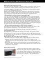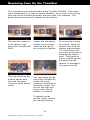
1
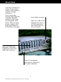
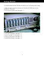
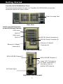
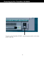
FIELD-READY
TranzStor
8X Raid
User Manual
1
Document# 27-0013UM Issued 4/02 Rev. 1.1 10/14/02
Z Microsystems
Regulatory
1. Use the power cables supplied with the
TranzStor 8X RAID to help prevent
interference with radio and television
reception. The use of cables and adapters
may cause interference with electronic
equipment in the vicinity of this unit.
2. This equipment is an
approved Class A
digital device, pursuant
to certain limits
imposed by Part 15 of
the FCC rules. These
limits are designed to
provide reasonable
protection against
harmful interference in
a residential installation. This equipment
generates, uses and
can radiate radio
frequency energy, and,
if not installed and
used in accordance
with the instructions,
may cause harmful
interference to radio
communications.
However there is no
guarantee that
interference will not
occur in a particular installation. If this
equipment does cause harmful interference,
to radio or television reception, which can be
determined by turning the equipment off and
on, the user is encouraged to try to correct
the interference by one or more of the
following measures:
• Reorient or relocate the receiving antenna.
• Increase the separation between the
equipment and receiver.
• Connect the
equipment into an outlet
on a circuit different
from that to which the
receiver is connected.
• Consult your dealer or
an experienced radio/TV
technician for help.
3. If necessary, the user
should contact the
dealer or an experienced
radio/television
technician for additional
suggestions. The user
may find the following
booklet, prepared by the
FCC, helpful: “How to
Identify and Resolve
Radio-TV Interference
Problems.” This booklet
is available from the
U.S. Government
Printing Office, Washington, DC, 20402,
Stock No. 004-00345-4.
TranzStor
8X Raid
Circuit Breaker (15A) Warning
This product relies on the building’s installation for short-circuit (overcurrent) protection. Ensure
that a fuse or circuit breaker no larger than 120 VAC, 15A U.S is used on the phase conductors (all current-carrying conductors).
No On/Off Switch Warning
This system does not have a power on/off switch that disconnects power from the system. To
completely remove power from the system, unplug the power cord.
2
Contents
Overview
Shipping contets
System Overview
Getting started
Rear Panel FC
Rear Panel SCSI
Inserting a PowerPak
Removing a PowerPak
TranzPak 7 Overview
Inserting the TranzPak 7
Removing the TranzPak 7
4
Frontplane
Controller Board
Removing a Controller Board
Installing a Controller Board
Fan
Removing a Failed Fan
Installing a New Fan
Front Panel Circuit Board
Removing a Front Panel Circuit Board
5
5
7
8
9
10
11
12
13
47
48
49
Installing a Front Panel Circuit Board
Powering uo the TranzStor 8X
14
RAID Controller Overview
15
Front Panel Overview
17
Status Indicators
Fan, RAID Controller Board, Internal Temperature, Dual Controller Binding, Disk Array
Alarm/Alarm Mute Button
Front Door Panel (Replacement)
System Expansion
Overview
50
Adding Cache Memory DIMMs
Considerations
DIMM Installation
51
Upgrading From a Single-Controller to a DualController Configuration
52
Installing a second Controller Board
Adding an Additional CRD-7220
Adding Disk Drives
RAID Controller Maintenance
53
Maintenance Information Overview
53
Cleaning Instructions
Step-by-Step Cleaning
Replacing Fans on the TranzStor
55
System Specifications
56
Enclosure
Environmental
Schematics
57
Warranty
58
Support
61
RMA Support
62
Considerations before installing
18
Fibre channel Considerarions
19
Cable distance
FC Configuration
Topology
Point to Point Topology
Arbitrary Loop
20
Arbitrary Loop with a Hub
21
Switched Fabric
Hubs and Switches
Hubs
Fibre Channel switches
23
Power considerations
24
Power Terminology
25
UPS Sizing Guidelines
26
Connecting the UPS Status Cable to the CDR7220
28
Cabling Instructions for Various UPS Systems
31
Configuration
34
Configurations Examples
35
Vision Storage Managemnet Utility (SMU)
42
Solaris Installation
43
Linux Installation
Firmware Updates
44
Firmware Update Considerations
System Shutdown
When firmware should be updated
FRU Description Overview
Access to RAID Controller
45
Removing RAID Door
FRU Status
FRU Status Indicators
46
FRU Replacement Overview
Removing/Replacing Front Door Panel
3
Document# 27-0013UM Issued 4/02 Rev. 1.1 10/14/02
Overview
Congratulations on selecting a
rugged field-ready TranzStor 8X RAID
-- the rugged mass storage system.
SHIPMENT CONTENTS
The TranzStor 8X RAID shipping box
contains the following:
• The TranzStor 8X RAID
• AC Power Cable
• User Manual
• SCSI Terminators
• 1 Pair of Rack Slides
• 1 Rack Mounting Hardware
Remember to save your original
shipping container and packing
material to transport or ship the
TranzStor 8X RAID.
User Manual
This Manual is also available on the
Z Microsystems web site
(www.zmicro.com).
We recommend you read this
manual as follows:
Carefully follow the instructions in the
Starting Point section for hookup and
initial control settings. Refer to the
Operation section for a complete
description of all the user controls.
4
Overview
TranzStor 8X RAID is a
family of high performance cross platform
network storage
solutions.
PRODUCT
DESCRIPTION
Front accessible
storage bays allow the
TranzStor 8X RAID
system to offer eight
hot-pluggable hard
drives, three hot plug
power supplies and
dual fibre channel or
SCSI RAID controllers.
Dual RAID controller.
With four 1GB/s Fibre
channel host ports or
4 SCSI ports, and
two Ultra SCSI LVD
drive channels
Eight removable hotpluggable TranzPak 7
ruggedized Ultra SCSI
wide disk modules.
Three hot-pluggable
load-sharing redundant
AC power modules.
5
Document# 27-0013UM Issued 4/02 Rev. 1.1 10/14/02
Getting Started
It is recommended that the TranzStor 8X RAID be set up following these steps:
1. Make all cable connections between the TranzStor 8X RAID and the host
computer(s). See page 2. Plug in the AC power cable. See page - 7
3. Insert the PowerPaks. See page - 9
4. Insert TranzPak 7’ns. See page - 12
5. Power up the system. See page - 14
6. Install RAID software. See page - 18
6
Getting Started
TranzStor 8X FC RAID Rear Panel
TheREAR
picture below
shows
the rear
of a TranzStor 8X
FC RAID
unit and the
VIEW
OF
TRANZSTOR
8X
FC RAID
connection points for these cables.
Dual hot swap fans
Rear View
FCAL Port 0 CTLR A
RS 232 Serial Controller A
FCAL Port 1 CTLR A
RS 232 Serial Controller B
FCAL Port 0 CTLR B
UPS Status input
FCAL Port 1 CTLR B
Ethernet 10 BaseT
Ethernet 10 BaseT
Controller B
Controller A
Left side connection panel
SCSI LVD/SE Channel 2
SCSI LVD/SE Channel 3
Install LVD Terminators
on these connectors
AC Power Input
Right side connection panel
7
Document# 27-0013UM Issued 4/02 Rev. 1.1 10/14/02
Getting Started
TranzStor 8X SCSI RAID Rear Panel
The
pictureVIEW
below shows
rear of a TranzStor
8X SCSI
RAID unit and the
REAR
OF the
TRANZSTOR
8X
FC RAID
connection points for these cables.
Dual hot swap fans
Rear View
Install one LVD Terminator
on each SCSI Host Channel
SCSI Host
CH2 I/O
SCSI Host
RS 232 Serial Controller A
CH3 I/O
RS 232 Serial Controller B
Ethernet 10 BaseT
Ethernet 10 BaseT
Controller B
Controller A
Left side connection panel
SCSI LVD/SE Channel 5
SCSI LVD/SE Channel 4
Install LVD Terminators
on these connectors or
use daisy chain to
another SCSI device
AC Power Input
Right side connection panel
8
Inserting the PowerPak
Loading a PowerPak
Inspect the rear connector to be
sure that it is clean and that there
are no bent pins.
Pull out the cam-locking-handle
out to prepare the PowerPak for
insertion.
Slide the PowerPak into the bay
until you can feel it touch off on the
rear panel connector.
Gently press the PowerPak onto
the rear panel connector.
Use the handle’s cam locking
action to fully seat the PowerPak in
the bay and on the rear connector.
Press the handles fully in to lock
the PowerPak in the bay and on
the rear connector. Inspect that the
cam locking pin is fully engaged.
9
Document# 27-0013UM Issued 4/02 Rev. 1.1 10/14/02
Removing the PowerPak
In the event of a power supply failure, the
PowerPak in question can be removed
and replaced without the system suffering any downtime (Power Module failure
is indicated with the red FAULT LED is lit.)
Gently pull out the cam
locking handle.
Grab the handle and
pull forward to extract
the rear connector from
the backplane.
Still holding the handle
continue pulling forward
until the PowerPak is
removed far enough to
be grasped by the body
and completely removed.
10
TranzPak 7 Overview
Red - SCSI Drive
Sliding Locking catch
Locking handle
High tensile diecast
aluminium alloy rear
panel
High tensile extruded
aluminium alloy thermoconductive body
High tensile diecast
aluminium alloy front
panel
Rear Connector
11
Document# 27-0013UM Issued 4/02 Rev. 1.1 10/14/02
Inserting a TranzPak 7
With the handle in the
open position, hold the
TranzPak 7 by the main
body and insert it
partially into the docking
bay. ( Be sure that it is
sliding on the black
guides).
Using your thumb push
the TranzPak 7 gently
into the bay ---
Check that the locking
catch is aligned with the
locking indent in the
slide rail and press the
handle towards body
until it snaps the
locking handle in place.
Check that all TranzPak
7 disk modules are
aligned across the face
of the 8X.
12
until you can feel it
touching off on the rear
connector.
Removing a TranzPak 7
Press down on locking
catch to allow locking
handle to spring open
Locking handle springs
open
Pull handle gently
forward to eject the
TranzPak 7 off of the
rear connector.
Continue to gently pull
handle gently forward to
slide the TranzPak 7
forward.
The TranzPak 7 should
slide over the grounding contacts until it is
half way out.
Grab the TranzPak 7 by
the main body and pull
straight out.
13
Document# 27-0013UM Issued 4/02 Rev. 1.1 10/14/02
Powering up the TranzStor 8X RAID
I
0
To power up the TranzStor 8X RAID- press the power switch on the lower
bottom right side.
14
RAID Controller Overview
CRD-7220 RAID Controller
Fibre Channel Arbitrated Loop
/ Ultra2 Low Voltage Differential SCSI
15
Document# 27-0013UM Issued 4/02 Rev. 1.1 10/14/02
RAID Controller Overview
Product Overview
The Fibre Channel (FC) interface implementation of the CRD-7220 makes it a
Storage Area Network (SAN) capable RAID
controller. The CRD-7220 is a ready-touse RAID controller consisting of a fully
integrated and tested hardware and
firmware combination. Selected highlights of the CRD-7220 are:
• Active / Active dual redundant RAID
controllers with mirrored cache
memory
• Support and compliance with striping
(RAID 0), mirroring (RAID 1), striping plus mirroring (RAID 0+1), parity RAID
(RAID 3/5), and JBOD (just a bunch of disks).
• Hot swappability of all critical components
• Automated host transparent fail-over and AutoRebindTM (fail-back)
• Two Ultra2 Low Voltage Differential (LVD) SCSI disk interfaces
• Storage capacity scaleability support for up to 28 disk drives
• High-performance architectural design and implementation
• Includes RAID Management System (RMS) management and control
software
• Network-based management of the RAID system using RMS
• Numerous ease-of-use, data-availability, integrity, and performance features
A more detailed description of many of the firmware features is available in
the RAID Management System manual. The basic hardware capabilities and
requirements are covered in this manual. Further detailed information on the
CRD-7220 is available by contacting the company where the storage system
was purchased, or visiting the CMD Technology, Inc. web site at http://
www.cmd.com.
CMD Titan™ Architecture
The CRD-7220 is a product developed from the CMD Titan™ architecture, a
third-generation RAID controller design. The focus of the architecture is to
provide a family of controllers that meet a wide range of user requirements,
with an emphasis on data availability, data integrity, and high performance.
CMD Titan products use the latest SCSI and Fibre Channel interface technologies, ensuring they are open systems compatible and capable of participating
in Storage Area Network (SAN) configurations.
Note:
To simplify instructions all references to the RAID Controller will be made to
the CRD 7220 Fibre Channel version. However, these instructions also
apply to the CRD 7040 ULTRA SCSI version as well.
16
The RAID Front Panel Overview
The CRD-7220 Front Panel Overview
The CRD-7220 is designed with an LED Front
Panel Display to assist with monitoring the
system. The front panel features status and
channel activity indicators. Depending on the
function, each indicator will be lit green, red, or be
turned off.
The status indicators provide instant visual
verification of the unit’s status. An alarm mute
button is also provided on the front panel.
The front panel communicates with each controller
independently through a separate serial interface.
Status Indicators
Fan, RAID Controller Board, Internal Temperature, Dual Controller Binding,
Disk Array
The operational status of each function is denoted by a bicolor LED indicator
located behind each appropriate icon on the front panel.
Indicator
Green
Red
Off
Fan
Functioning
Not Functioning
-ORNot Present
Never
RAID Controller
Board (2)
Functioning
(blinking)
Not Functioning
Not Present
Within Normal
Temperature
Outside Normal
Temperature
Never
Dual Controller
Status
Dual
Controllers
Bound
Dual
Controllers
Not Bound
System
Configured with
Single Controller
Disk Array
Functioning
RAID Set
Degraded
Never
Internal
Temperature
Alarm/Alarm Mute Button
A single audio alarm is shared by both RAID controller boards and used to
indicate significant system failures. A single momentary push button is used
to mute the audio alarm. The mute button mutes only the current alarm
condition. Any new alarm condition will cause the audio alarm to resume.
17
Document# 27-0013UM Issued 4/02 Rev. 1.1 10/14/02
RAID Controller Overview
Considerations Before Installation
Storage Considerations
Disk Drive Interface Requirements
The CRD-7220 RAID controller supports SCSI disk drives that conform to:
ANSI X3.277-1996 Information Technology - SCSI-3 Fast-40
ANSI X3T10/
1142M 1998/04/
13 Rev 20b
SCSI Parallel
Interface-2
(SPI-2)
Note: For optimum performance, SCSI Ultra2 requires the
use of approved disk drives and disk drive enclosures in
addition to using the highest quality cables and terminators
available (see page 4-2).
ANSI specifications are outlined above. The SPI-2 specification for Ultra2 requires the use of
Low Voltage Differential (LVD) as the physical connection with provision for
backwards compatibility with single-ended (SE) connections running at Ultra
SCSI rates. The CRD-7220 does support a mixture of Ultra and Ultra2 devices
connected to the SCSI channels, with the restriction that the SCSI channel will
transfer data at a rate directly
related to the device type conTerminator
nected.
CRD-7220
LVD
For example, if Ultra (SE) and
Ultra2 (LVD) devices are connected on the same SCSI channel, the CRD-7220 will negotiate
the transfer at the fastest speed
possible for the SE connections
which is Ultra.
In addition, if all devices on the
channel support Ultra2 but the
terminator is SE, then again the
CRD-7220 will only negotiate at
Ultra.
Ultra2
LVD
Ultra
SE
Ultra2
LVD
Ultra
SE
Terminator
SE
CRD-7220
Ultra2
LVD
Ultra2
LVD
Ultra2
LVD
Ultra2
LVD
Terminator
LVD
CRD-7220
The only way to negotiate at Ultra2
speed is to have all devices be
Ultra2 (LVD) and the terminator LVD.
Ultra2
LVD
18
Ultra2
LVD
Ultra2
LVD
Ultra2
LVD
RAID Controller Overview
Fibre Channel Considerations
Fibre Channel Type
The CRD-7220 connects to the Host System using Fibre Channel cable. The
CRD-7220 uses copper 3-pin header technology (PTP).
Cable Distance
Copper 3-pin header technology (PTP) allows for a maximum cable length of
13 meters from controller backplane to hub.
Fibre Channel Configurations
To properly select the correct Fibre Channel configuration for any given
application, many factors including flexibility, accessibility and performance
must be considered.
Topology
Topology defines how components of a network are connected. Fibre
Channel supports three(3) topologies which offer various benefits: Point-toPoint, Switched Fabric and Loop. The Point-to-Point connection is a dedicated
channel which offers a single connection with dedicated bandwidth. Switched
Fabric offers up to 16 million connections with scaled performance. An
Arbitrated Loop topology offers limited connections with shared performance.
A loop not connected to any Fibre Channel switch is called a Private Loop,
otherwise it is considered a Public Loop.
Point-to-Point Topology
The Point-to-Point connection is the simplest topology with two N_Ports (such
as a Host and RAID controller) connected. This topology has limited applications with no expansion capabilities but can serve as a high speed interface
between two points over
long distances. The
communication is full
duplex so a 1 gigabit/
second link delivers
19
Document# 27-0013UM Issued 4/02 Rev. 1.1 10/14/02
RAID Controller Overview
200MB/s of dedicated
bandwidth. Because no
additional devices are
necessary, a Point-toPoint configuration is a
lower cost solution.
L_Port
Arbitrated Loop
L_Port
Tx
Rx
Rx
Tx
Tx
Rx
Rx
Tx
L_Port
L_Port
Fibre Channel Arbitrated Loop (FC-AL)
provides a low cost alternative which allows multiple connections without the
aid of a switch. Up to 127 ports (L_Port) can be connected to any loop with
each port sharing the bandwidth. The connection is half-duplex which means
once a port arbitrates and gains access to the loop, transmission of information is in one direction only. This effectively opens a point-to-point connection
utilizing ½ of the available loop bandwidth.
An arbitrated loop consists of a hierarchical structure with each node assigned either a user-defined “hard” address or a system-defined “soft”
address. When a device has data to transfer, it places a request in queue on
the loop. The request travels the loop with an arbitration at each node. If the
requesting node has higher priority, then it continues on the loop to the next
node. If the visited node has higher priority, then that node decides whether or
not it wants the loop. If it does want the loop, the requesting node must wait. If
the visited node doesn't want the loop, then the requesting node travels on.
Once the request travels the entire loop and returns to the sender, then data
can be transferred. No other data transfer activity takes place until this transfer
is complete. When the transfer is finished, the next transfer request in the
queue is arbitrated.
20
RAID Controller Overview
Arbitrated Loop with a Hub
An arbitrated loop with a Hub performs in a manner similar to an arbitrated
loop, except that the Hub provides loop resiliency if any device fails. Because
Fibre Channel loops can be connected port to port, if a device fails, the loop is
broken and accessibility is lost to all devices on the loop. The Fibre Channel
Hub overcomes this
problem by creating a
star configuration
similar to that which
Rx
Tx
Tx
Rx
can be used with a
L_Port
L_Port
Rx
Tx
Tx
LAN. If any of the links
Rx
fail, the Hub disconHub
nects the port and
‘heals’ the loop to
Tx
Rx
Rx
Tx
guarantee its resiliency.
L_Port
L_Port
Rx
Tx
Rx
Tx
Switched Fabric
A Switched Fabric allows the user to expand up to 16 million connections. The
Fibre Channel Switch is analogous to the Router in networking, managing
connections, routing requests to the proper ports, and allowing characteristics
to be set on each port. A switch will also automatically configure the port for
point-to-point (F_Port) or loop operation (FL_Port). Once configured for the
correct topology, the
user can select the type
of service required by
the application deterSwitched Fabric
mining the performance
F_Port
F_Port
FL_Port
level of the connection.
Traditionally, switches
have been high cost
items. The CRD-7220
is not designed for use
in a switched fabric
N_Port
N_Port
NL_Port
topology where the
switch does not include
a FL_Port.
Hubs and Switches
Hubs and switches are used to connect elements of a storage system (hosts,
controllers, disk drives and other devices) to each other in various topologies.
Hubs
A hub is a network device used to guarantee the loop resiliency of an arbi21
Document# 27-0013UM Issued 4/02 Rev. 1.1 10/14/02
RAID Controller Overview
trated loop. If a device fails on an arbitrated loop, the loop is broken and
accessibility to all devices on the loop is lost. A hub prevents this problem by
creating a star configuration similar to that which can be used with a LAN.
Hubs use Port Bypass Circuits (PBCs) to detect when different devices are
installed onto the network and then automatically assembles these devices
into the loop. More importantly, hubs detect failures and automatically
restructure the loop to bypass the down connection. Hubs are available with 8
to 12 ports allowing multiple hubs to be connected forming loops up to 127
ports.
22
RAID Controller Overview
Fibre Channel Switch
An Arbitrated Loop does not fit all applications due to limited connections and
bandwidth. A switch is a network device which creates point-to-point and loop
topologies between individual data network elements on an "as-needed"
basis.
The Fibre Channel Switch overcomes this constraint allowing point-to-point
and loop topologies to be connected into a Fabric. The Fabric is loosely
woven connections which can be configured for specific applications.
The Fibre Channel ANSI specification identifies classes of service which can
be used to tailor the connection;
•
•
•
•
•
Class
Class
Class
Class
Class
1 is a dedicated connection service
2 is a guaranteed delivery service
3 is a datagram service, no guaranteed delivery
4 is a guaranteed bandwidth service
6 is a dedicated unidirectional service
The Fibre Channel switch has two methods of operation; frame and circuit
switching. The frame switching method is used for class 2, 3 and 4 while
circuit switching is used for class 1 and 6. The circuit switch is a physical
connection between ports while the frame switch creates a virtual connection
utilizing buffering between ports. The switch will support all topologies and
can configure each port for point-to-point (Fabric port or F_Port) or loop
operation (Fabric Loop port or FL_Port). This allows low -cost loop-only
devices to become part of the Fabric (Public Loop).
The Fibre Channel Switch is used for applications that require increased
bandwidth, connections and delivery service beyond loop or point-to-point
configurations. The switch is highly flexible and easily configured making it
the choice for enterprise-level applications.
When a node has data to transfer, it tells the switch which node it wants to
send to. The switch makes the connection to the requested destination node,
and the data is transferred. This occurs totally independent of any other data
transfer activity: since each node has both transmit and receive ports, all
nodes in a switch-based network can conduct data transfers at any time.
23
Document# 27-0013UM Issued 4/02 Rev. 1.1 10/14/02
Power Considerations
Power Considerations
All CMD Titan RAID Controllers have a unique architecture that, in the event of
a power failure, dumps the contents of its internal memory to non-volatile hard
disk. This assures, regardless of the duration of the power failure, the data
will be protected and available once power is restored.
An Uninterruptible Power Supply (UPS) is provided for the CRD-7220 controller. The UPS keeps the system powered long enough for the controller to
write its internal memory to a specified area of hard disk (usually no more
than 5 minutes). The UPS provides a signal to the CRD-7220 that indicates
that line power has failed and also informs the controller about the condition
of the UPS batteries.
Another benefit to the Titan architecture is that most UPS systems are highly
reliable and have many sophisticated
features like power line monitoring, data
logging, early warning alarms, etc.
Note: These are approximate
guidelines. Please use the disk
drive and enclosure manufacturPower Protection for the CRD-7220
ers' values for more exact power
The CRD-7220 must be connected to a
estimates.
UPS system to prevent data loss during
a power failure. The UPS status inputs
provide the CRD-7220 system with early warnings regarding UPS conditions.
Power Protection with a site UPS
or Series Connecting of UPS Systems
The UPS inputs will not be required if the entire system is backed up on a site
UPS. However, if there is any chance of failure for the site UPS, a second
local UPS will be required to protect the RAID sub-system.
If the site where the CRD-7220 is being installed is equipped with a site-wide
UPS system or backup generator, great care must be taken when selecting a
UPS to be connected in series with the site-wide system. There are a number
of compatibility issues that can potentially cause problems. The Facilities
Manager should be consulted before selecting a local UPS for the CRD-7220.
The UPS models listed at the end of this section indicate which models are
suitable for series connection to a site-wide system. This does not guarantee
the system will work with any site UPS. The manufacturers of both the UPS
systems should be contacted for known incompatibilities, as well as the
Facilities Manager for the site.
24
Power Considerations
Selecting a UPS
When selecting an Uninterruptible Power Supply (UPS) there are many factors
that must be considered. Where the UPS is being installed is an important
factor. Some areas are prone to certain types of power problems:
• Blackouts - a complete loss of power
• Sags (also called brownouts) - line voltage dips below the nominal voltage
• Surges - line voltage rises above nominal voltage
• Transients / Noise - distortions of the line voltage waveform
It is a good idea to understand what types of problems are most common,
how often they occur, and how long they last. Some UPS systems can handle
a blackout well, but do not offer good protection from brownouts.
Some buildings have backup generators or a site UPS, but a local UPS
system is deemed necessary due to reliability or switching issues. The
combination of a site UPS feeding a local UPS system can be unstable. In
these cases extra care must be taken to insure the local UPS is compatible
with the larger system.
Most good UPS systems have digital outputs to indicate that power has failed
and alarm signals to indicate the state of the batteries. Many also have
software included for monitoring the incoming AC Line for the above conditions and logging the data, shutting down computer systems gracefully, etc.
Power Terminology
Most UPS manufacturers rate their systems in Volt Amps (VA). Some also
include a rating in Watts (W). There is an important difference between the
two ratings.
Power Factor (FP) is defined as the ratio of active power to apparent power.
Apparent power is defined as the Root Mean Squared (RMS) value of the
voltage waveform multiplied by the RMS value of the current waveform
(expressed in VA). This is a measure of the total average power.
The active power is defined as the RMS value of the voltage waveform
multiplied by the RMS value of the "in-phase" component of the current
waveform (expressed in W). This component of the power is responsible for
producing the heat generated by electronic components.
25
Document# 27-0013UM Issued 4/02 Rev. 1.1 10/14/02
Power Considerations
The Power Factor gives an indication of what fraction of the apparent power is
due to the active power. A purely resistive load (such as a heater or light bulb)
has a power factor of 1 (Power Factors can not be greater than 1). Electronic
devices (such as switching power supplies) do not draw sinusoidal currents
and usually have power factors on the order of (0.6 to 0.8).
Example 1
• Power Factor = 1
• A 220V @ 1 Amp resistive heater will have an apparent power of 220VA and
an active power of 220W.
Example 2
• Power Factor = 0.7
• A switching power supply with a power factor of 0.7 and rated at 120VAC @ 4
Amps will have an apparent power of 480 VA and an active power of 480 * 0.7
= 336 Watts.
Most UPS systems are not designed to deliver their full rated power (VA) into
purely resistive loads. They are typically designed for power factors as low as
0.6. This means that a UPS rated for 400VA could only supply 240 Watts of
active power.
Care must be taken that the load does not exceed either of the power ratings,
the apparent power rating (VA) or the active power rating (W). Some UPS
manufacturers do not give a specification of rated power in Watts. If the rating
cannot be obtained, the worse case power factor of 0.6 should be used to
calculate wattage rating.
Example 3
• A UPS system is rated at 1000VA and no active power is specified. It would
be safe to assume that the active power rating is 600 W.
UPS Sizing Guidelines
When selecting a UPS system for use with the CRD-7220, the power requirements for the shutdown mode must be determined.
1. Determine the number of disk drive enclosures that will be connected to
26
Power Considerations
the UPS. Systems utilizing a dump area may not require the entire disk array
to be connected to the UPS. If the disk array consists of multiple disk enclosures, only the disk enclosure that contains the drive(s) mapped as "dump
area" need to be powered by the UPS. The other enclosures should be direct
connected to utility power. If the disk array contains only one drive enclosure,
it should be powered by the UPS.
If there are plans to increase the array size in the near future, and those drives
need to run off of the UPS, they should be included in the power estimate so
the UPS will be sized correctly to handle them.
2. Determine the power required by the drive enclosures. Most disk drives
draw about 10 Watts under average conditions. However, 16 Watts should be
used for sizing the UPS. This is because the new 10,000-RPM disk drives
actually draw this much peak power when active, and during an emergency
shutdown, the drives will be very active.
The following are some typical numbers for the power required from
various components, be sure to use the manufacturer's specifications when
possible:
Disk Drive
à 16 Watts
(Be sure to use the power specified for
an active drive, not the idle spec).
5" Axial Cooling Fan
à 12 Watts
3½" Axial
à 6 Watts
Enclosure
Electronics
à 5 Watts
Note: A UPS should not be operated at more than 80% of its
rated capacity as this will cut its run time by more than 50%.
Be conservative when determining UPS requirements.
Equation for
Total Watts
(# Drives * 16W) + (# 5" Fans * 12W) + (#3.5" Fans * 6W) + (Enclosure) +
(60W CRD-7220) = Total Watts
Take the sum of all the UPS powered drives, fans, enclosure power and the
60W required by the CRD-7220. The result is the continuous power required
by the raid subsystem. If the host or any other loads are connected to the
same UPS, this additional power requirement must be included.
27
Document# 27-0013UM Issued 4/02 Rev. 1.1 10/14/02
Power Considerations
Total the number of drives in each enclosure, then multiply the number of
drives by 16 Watts.
Add about 12W for each 5” axial cooling fan, and use 6W for each 3.5” axial or
small squirrel cage fan.
Add another 5W for any local drive enclosure displays or environmental
controller.
Add the sum of all the UPS-powered drives, fans, and enclosure power to the
60W required by the CRD-7220.
Example
x10 Drives, x2 5" Fans, 5W Enclosure Electronics
(10 * 16W) + (2 * 12W) + (5W) + (60W) =
(160W) + (24W) + (5W) + (60W) = 249 Watt Load
At this point the size of the UPS may be determined. The active power that the
UPS will need to supply has been calculated in Watts. If the UPS manufacturer only provides a Volt Amp (VA) rating, the power calculated is converted to
VA by dividing the active power (Watts) by the worse case power factor of 0.6.
Example
• The required power in VA = 249 Watts / 0.6 = 415 VA Load
Example
• The minimum VA rating for the UPS = 415VA * 1.25 = 519VA Rated UPS
minimum.
Current estimates place the CRD-7220 shutdown time at about 5 minutes
worst case. A typical hold up time for a UPS is about 12 minutes at a 60 to
80% load. Actual UPS holdup time will vary from one manufacturer to another
so make sure this time is a guaranteed minimum time, not a theoretical
maximum.
Connecting the UPS Status Cable to the CRD-7220
The CRD-7220 requires four signal connections for each UPS Status port.
28
Power Considerations
The UPS ports on the backplane are 4-pin male connectors; J8 and J16.
(Refer to backplane diagrams on pages 4-6 and 4-7.) The qualified UPS
vendors all supply simple open collector or dry contact relays for signaling the
CRD-7220 of a change in UPS status. While other more sophisticated
features may be supported by qualified UPS suppliers, there is no standardization amongst the various vendors, therefore these features are not supported through the CRD-7220 UPS interface. A direct connection between the
UPS and host is required if it is desirable to access these additional UPS
capabilities.
An adapter cable is supplied to interface the CRD-7220 backplane to the DB9
bulkhead connector on the disk enclosure. Refer to the diagram on the
following page.
The type of UPS interface used on the CRD-7220 is commonly called an
"AS400" interface by many UPS vendors. The required UPS port signals for
the CRD-7220 are:
Pin Number Signal
Pin 2
Description
AC Fail
Active low connection indicating the loss of
AC input power to the UPS.
This signal is a 3.3V CMOS input with a 10K pull-up
resistor to 3.3Volts. This signal will be shorted to
ground by the UPS when the input AC power to the
UPS is removed.
Pin 4
Presence
Pin 3 Signal Ground
Active low connection indicating the presence of a
UPS. This signal is a 3.3V CMOS input with a 10K pull
up resistor to 3.3 Volts. This signal will be shorted to
ground by the UPS when the cable is connected to the
UPS. It is not recommended to use a shield or AC
ground for this signal as the UPS may not connect
these signals to DC ground internally. The presence
signal may be connected to any normally closed side
of one of the other signal relays to make a connection
to ground. (This is because presence is assumed
true because of the redundant connection created by
any other UPS alarm condition).
This is the signal ground between the UPS and the
CRD-7220.
29
Document# 27-0013UM Issued 4/02 Rev. 1.1 10/14/02
Power Considerations
Pin 1 2 Min. Warning
Pins 5-9
Active low signal used to indicate the UPS batteries
are almost exhausted. This signal is a 3.3V CMOS
input with a 10K pull-up resistor to 3.3 Volts. This
signal will be shorted to ground by the UPS when the
backup battery has about two minutes of power left.
No connection
30
Power Considerations
Cabling Instructions for Various UPS Systems
Note: Systems capable of series
connection are so indicated. Pins that
are not shown are not connected (open).
The following diagrams detail
the connections for the cable
from the enclosure backplane
to each specific UPS.
APC - Smart-UPS
Model numbers: SU700RMNET,
SU1000RMNET, SU1400RMNET, SU2200RM3U, SU3000RMSU.
APC units must be equipped with
the optional Smartslot relay I/O
module, AP9610.
Caution: When using an APC UPS, the
UPS Self-Test must be disabled.
7000 Series UPS Interface,
9-pin DB9 (female)
UPS Connector,
DB25 (male)
AC_Fail Input
2
1
Presence Input
3
24
Ground
Ground
4
23
Ground
Low Batt Input
5
AC_Fail N.O.
2
AC_Fail COM
15
Low Batt COM
14
Low Batt N.O.
Intellipower
*** Suitable for series connection ***
Model numbers: IQ-650, IQ-800, IQ-1100, IQ-1500
7000 Series UPS Interface,
9-pin DB9 (female)
UPS Connector,
DB15 (male)
AC_Fail Input
2
7
AC_Fail N.O.
Presence Input
3
4
Ground
Ground
4
2
Ground
Low Batt Input
5
31
Document# 27-0013UM Issued 4/02 Rev. 1.1 10/14/02
6
AC_Fail COM
15
Low Batt COM
14
Low Batt N.O.
Power Considerations
Liebert - PowerSure Series
*** Suitable for series connection ***
Model numbers: PS700RM-120, PS1000RM-120, PS1400RM-120,
PS2200RM-120
Liebert Systems must be equipped with the Intellislot AS400 Card option.
7000 Series UPS Interface,
9-pin DB9 (female)
UPS Connector,
DB25 (male)
2
16
Presence Input
3
6
Summary Alarm N.C.
Ground
4
7
Signal Ground
9
Low Battery Common
AC_Fail Input
Low Batt Input
5
AC_Fail N.O.
17
Other Common
11
Low Batt N.O.
Liebert - UPStation GXT Series
*** Suitable for series connection ***
Model numbers: GXT700, GXT1000, GXT1500, GXT2000, GXT3000
Liebert Systems must be equipped with the Intellislot AS400 Card option.
7000 Series UPS Interface,
9-pin DB9 (female)
UPS Connector,
DB25 (male)
2
16
Presence Input
3
6
Summary Alarm N.C.
Ground
4
7
Signal Ground
9
Low Battery Common
AC_Fail Input
Low Batt Input
5
32
AC_Fail N.O.
17
Other Common
11
Low Batt N.O.
Power Considerations
MGE - EX Series
Model numbers: EX10, EX15, EX20, EX30.
MGE Systems must be equipped with the 8902AS Relay Interface Card option.
7000 Series UPS Interface,
9-pin DB9 (female)
UPS Connector,
DB9 (male)
AC_Fail Input
2
9
AC_Fail N.O.
Presence Input
3
4
AC Fail N.C.
Ground
4
5
Ground (COM)
Low Batt Input
5
7
Low Batt N.O.
MGE - ESV+ Series
Model numbers: ESV8+, ESV11+, ESV14+, ESV22+.
MGE Systems must be equipped with the 8902AS Relay Interface Card option.
7000 Series UPS Interface,
9-pin DB9 (female)
UPS Connector,
DB9 (male)
AC_Fail Input
2
9
AC_Fail N.O.
Presence Input
3
4
AC Fail N.C.
Ground
4
5
Ground (COM)
Low Batt Input
5
7
Low Batt N.O.
33
Document# 27-0013UM Issued 4/02 Rev. 1.1 10/14/02
Configuration
34
Configuration
Configuration Examples
Overview
This section will illustrate several cabling configurations using various Fibre
Channel topologies. Because of the flexibility of the CRD-7220 and the variety
of Fibre Channel topologies, it is not practical to show all of the configurations
possible for this product. Diagrammed are some of the most common
configurations possible.
For storage system resiliency, it is advisable to implement a hub between the
host computer(s) and the CRD-7220, with one hub for each loop. Should a
controller fail and require a hot-replacement, the loop will remain intact if a
hub is used. Without a hub, removal of a controller will break the loop.
Host
Host
Fibre
Channel
HBA
Fibre
Channel
HBA
Fibre
Channel
HBA
Fibre Channel Hub
Enclosure w/bulkhead connectors
R
T
R
T
R
Backplane
0
1
FCAL
FCAL
T
R
T
R
T
R
Backplane
1
FCAL
FCAL
0
1
FCAL
FCAL
Failover Bus
CRD-7220 Active Controller
Ultra2
T
0
CRD-7220 Active Controller
Ultra2
Ultra2
Ultra2
Up to 28 Ultra2
SCSI disk drives
Host
Fibre Channel Hub
T
Fibre
Channel
HBA
Fibre Channel Hub
T
R
T
R
T
R
Backplane
0
1
FCAL
FCAL
0
1
FCAL
FCAL
Failover Bus
CRD-7220 Active Controller
Ultra2
Ultra2
Ultra2
Up to 28 Ultra2
SCSI disk drives
Fibre
Channel
HBA
R
CRD-7220 Active Controller
CRD-7220 Active Controller
Ultra2
Ultra2
Ultra2
Up to 28 Ultra2
SCSI disk drives
Enclosure w/bulkhead connectors
35
Document# 27-0013UM Issued 4/02 Rev. 1.1 10/14/02
Configuration
Host
Host
Fibre
Channel
HBA
Fibre
Channel
HBA
Fibre Channel Hub
R
T
R
Fibre Channel Hub
T
R
T
R
T
Backplane
0
1
FCAL
FCAL
0
1
FCAL
FCAL
Failover Bus
CRD-7220 Active Controller
Ultra2
CRD-7220 Active Controller
Ultra2
Ultra2
Ultra2
Up to 28 Ultra2
SCSI disk drives
Host
Fibre
Channel
H BA
Host
Fibre
Channel
HBA
Fibre
C hannel
HB A
Fibre Channel Hub
R
T
R
Fibre
Channel
H BA
Fibre Channel Hub
T
R
T
R
T
Backplane
0
1
FCAL
FCAL
0
1
FCAL
FCAL
Failover Bus
CRD-7220 Active Controller
Ultra2
Ultra2
CRD-7220 Active Controller
Ultra2
Ultra2
Up to 28 Ultra2
SCSI disk drives
36
Configuration
Configuration Example 1
The following is a non-redundant CRD-7220 configuration example of a
single host with a single FCAL HBA connected to one of the CRD-7220's Fibre
Channel loop ports. In this point-to-point configuration, should controller, HBA
or Fibre Channel cable fail, data access to the host is lost. Optionally,
denoted by doted lines, a second FCAL HBA may be added to connect to the
second FCAL loop port on the CRD-7220. In this optional configuration, if an
HBA or Fibre Channel cable fail, data access can continue over the surviving
loop. As with all dual HBA-per-host configurations, the host software must be
capable of supporting multiple connections to the same controller for this
topology to be viable.
Host
Fibre
Channel
HBA
Fibre
Channel
HBA
Enclosure w/bulkhead connectors
R
T
R
T
Backplane
0
1
FCAL
FCAL
CRD-7220 Active Controller
Ultra2
Ultra2
Up to 28 Ultra2
SCSI disk drives
37
Document# 27-0013UM Issued 4/02 Rev. 1.1 10/14/02
Configuration
Configuration Example 2
The following is an example of a single host with a single FCAL HBA connected to a CRD-7220 dual redundant configuration. It is the simplest
example of a single loop Fibre Channel topology. In this configuration, should
an HBA or Fibre Channel cable fail, data access is lost. With this configuration, no special host software capabilities are needed for the controllers to
perform a failover of resources should a failure occur.
Host
Fibre
Channel
HBA
Fibre Channel Hub
R
T
R
T
R
T
R
T
Backplane
0
1
0
1
FCAL
FCAL
FCAL
FCAL
Failover Bus
CRD-7220 Active Controller
Ultra2
CRD-7220 Active Controller
Ultra2
Ultra2
Ultra2
Up to 28 Ultra2
SCSI disk drives
38
Configuration
Configuration Example 3
The following is an example of a single host with dual FCAL HBAs connected
to a CRD-7220 dual redundant configuration. It is the simplest example of a
dual loop Fibre Channel topology. In this configuration, should an HBA or
Fibre Channel cable fail, data access can continue over the surviving loop. As
with all dual HBA-per-host configurations, the host software must be capable
of supporting multiple connections to the same controller for this topology to
be viable.
Host
Fibre
Channel
HBA
Fibre Channel Hub
Fibre Channel Hub
T
R
Fibre
Channel
HBA
T
R
T
R
T
R
Backplane
0
1
0
1
FCAL
FCAL
FCAL
FCAL
Failover Bus
CRD-7220 Active Controller
Ultra2
CRD-7220 Active Controller
Ultra2
Ultra2
Ultra2
Up to 28 Ultra2
SCSI disk drives
Enclosure w/bulkhead connectors
39
Document# 27-0013UM Issued 4/02 Rev. 1.1 10/14/02
Configuration
Configuration Example 4
The following is a dual redundant CRD-7220 configuration example of a dual
hosts with single FCAL HBAs in each host connected to separate CRD-7220
Fibre Channel loops. In this configuration, a host could be homogeneous or
heterogeneous and each host would be mapped to separate redundancy
groups unless the operating system(s) were fully clusterable and running
lock managers. In this configuration, should an HBA or Fibre Channel cable
fail, data access to the one host is lost but can continue on the other host.
Host
Host
Fibre
Channel
HBA
Fibre
Channel
HBA
Fibre Channel Hub
R
T
R
Fibre Channel Hub
T
R
T
R
T
Backplane
0
1
0
1
FCAL
FCAL
FCAL
FCAL
Failover Bus
CRD-7220 Active Controller
Ultra2
CRD-7220 Active Controller
Ultra2
Ultra2
Ultra2
Up to 28 Ultra2
SCSI disk drives
40
Configuration
Configuration Example 5
The following is a dual redundant CRD-7220 configuration example of dual
hosts with dual FCAL HBAs in each host connected to separate CRD-7220
Fibre Channel loops. In this configuration, if an HBA or Fibre Channel cable
fails, data access can continue over the surviving loop. As with all dual HBAper-host configurations, the host software must be capable of supporting
multiple connections to the same controller for this topology to be viable.
Host
Fibre
Channel
HBA
Host
Fibre
Channel
HBA
Fibre
Ch a n n e l
HBA
Fibre Channel Hub
Fibre Channel Hub
T
R
T
R
Fibre
Ch a n n e l
HBA
T
R
T
R
Backplane
0
1
0
1
FCAL
FCAL
FCAL
FCAL
Failover Bus
CRD-7220 Active Controller
Ultra2
CRD-7220 Active Controller
Ultra2
Ultra2
Ultra2
Up to 28 Ultra2
SCSI disk drives
41
Document# 27-0013UM Issued 4/02 Rev. 1.1 10/14/02
SMU
Vision Storage Management Utility (SMU)
Installation Instructions
Introduction
The Vision Storage Management Utility (SMU) CD provides multi-platform
installation for all supported platforms. The CD contains platform specific
setup files for automatic installation of the software along with directories to
support the manual installation of the software. Every platform directory has a
readme text file that outlines the steps necessary to manually install the
application on the target system.
In addition to the SMU software, this CD also contains User Manuals for all
products supported along with the Vision Storage Management Utility (SMU)
Users Manual. This is a complete guide to the JAVA application and should be
read before attempting to utilize the software.Installation
Overview
Setup can be run directly from the CD on most systems. To properly install the
software, a JAVA Runtime Environment (JRE) revision 1.3.0 or higher must be
available on the target system. In the event a JRE cannot be automatically
located, a command line option can be used to direct the installer. The
command line option -is:javahome <directory> will direct the installer to
search the given path for a JRE. Once located, it will verify that the installed
JRE is revision 1.3.0 or higher and continue the installation procedure.
If manual installation is required, all of the necessary files and the installation
instructions can be found in the platform specific directory on the CD. Unix
platform directories include a TAR file, Windows a ZIP that contains all files
required to install product.
Windows Installation
The SMU application can be installed on any Windows 98,Me,NT or Windows
2000 system with a JRE 1.3.0 or later. The software is installed by accessing
the CD and running setup.exe located in the Files folder. Once active, follow
the instructions to properly install the software on the target platform.
If installation of the software is not successful, the files can be copied from
the CDROM and placed in the appropriate directories. Please locate the
readme.txt file in the Windows directory for further instructions on the manual
installation procedure.
42
SMU
Solaris Installation
The application can be installed on any Solaris 2.7 or 2.8 platform with JRE
1.3.0 or later installed. The software can be installed by accessing the
CDROM through the desktop or terminal window and running setupsparc.sh.
Once active, follow the instructions to properly install the software.
If installation of the software is not successful, the files can be copied from
the CDROM and placed in the appropriate directories. Please locate the
readme.txt file in the Solaris directory for further instructions on the manual
installation procedure.
Linux Installation
The application can be installed on any RedHat Linux platform with JRE 1.3.0
or later installed. The software can be installed by accessing the CDROM
through the desktop or terminal window and running setuplinux. Once active,
follow the instructions to properly install the software.
If installation of the software is not successful, the files can be copied from
the CDROM and placed in the appropriate directories. Please locate the
readme.txt file in the Linux directory for further instructions on the manual
installation procedure.
43
Document# 27-0013UM Issued 4/02 Rev. 1.1 10/14/02
RAID Firmware Updates
POWER MODULE
Firmware Updates
Periodically, the firmware in the CRD-7220 will be updated to add features
and/or make any necessary corrections to the existing firmware. For periodic
notices of firmware updates refer to Z Microsystems’ website at:
www.zmicro.com.
Firmware Update Considerations
It is not always necessary to immediately update firmware, especially if there
are no problems with one’s current data storage system. It is very important to
understand why a firmware update has been released. Each release is
accompanied with a notice which explains the purpose of the update and any
prerequisites for proper installation.
System Shutdown
In order to update the firmware in either a single or dual-controller configuration, the entire storage system is required to be shut down and restarted after
installation.
When firmware should be updated
Firmware updates are released for two primary reasons:
1. The release of newly-developed additional features; and/or
2. Necessary corrections to resolve problems discovered during use in the
field.
Firmware updates do not normally change the existing functionality of the
system. Instead, updates enhance and improve existing firmware functionality.
Updating firmware after missing previous update
During the installation of a firmware update, the old version is erased when
the new version is installed. If previous firmware revisions were not installed,
refer to the Firmware Release Notes to verify proper installation requirements.
Returned Materials Authorization (RMA) Instructions
End users with questions regarding, or problems attributed to, the CRD-7220
should contact Z Microsystems.
FRU Description Overview
All major components in the CRD-7220 have been designed to be exceptionally simple to replace. The Field Replaceable Units (FRUs) are:
• Controller Board Assemblies (including Daughter Cards)
44
Access to RAID Controller Boards
Before the RAID Controller can be
accessed, the RAID door retaining
plate must be removed.
Follow these steps to
remove the door
retaining plate.
NOTE: It is not necessary to turn off
power to the system. The
RAID controller is it hot
swappable.
Loosen the left and
right thumb screws on
the RAID controller
retaining cover.
The retaining cover will
hinge up and can be
removed.
Then disengage the
hinge tabs on the left
side of the front door
panel from the slots in
the CRD-7220 canister.
Finally, remove the front
door panel.
Removing the RAID door
Remove the front door
panel by gently pulling
down the front panel
latch lever located to the
right of the System
Status indicators. This
unlocks the front door
panel from the canister
allowing the front door
panel to be opened.
45
Document# 27-0013UM Issued 4/02 Rev. 1.1 10/14/02
Access to RAID Controller Boards
CLEAN FRONT P
ANEL
PANEL
• Front Plane
• Fans
• Front Door Panel (Beige or Black)
• Front Panel Circuit Board
All FRUs may be removed and installed through the front door panel. No
access to the rear of the CRD-7220 canister is required. Only the Front Panel
Circuit Board and Front Door Panel require any tools for replacement.
FRU Status Indicators
The front panel LED illuminates solid or blinking green during normal
operation, and turns solid red when the component fails. No other display
states are valid: except that the Disk Controller Status indicator will not be lit if
there is only one Controller Board in the canister. Each FRU Status Indicator
will always be consistent with its corresponding indicator on the front door
panel.
FRU Replacement Overview
In the event of a component failure, an alarm will sound, a solid red LED on
the front door panel will be illuminated, and an Alert message will appear on
the RAID Management Software (RMS). To turn off the alarm sound, press the
Alarm Mute button located on the front door panel.
Removing/Replacing Front Door Panel
Remove the front door panel by gently pulling
down the front panel latch lever located to the right
of the System Status indicators. This unlocks the
front door panel from the canister allowing the front
door panel to be opened. Then disengage the
hinge tabs on the left side of the front door panel
from the slots in the CRD-7220 canister. Finally,
remove the front door panel.
Replace the front door panel by first placing the
hinge tabs on the left side of the front door panel
into their respective slots in the CRD-7220
canister. Swing the front door panel into place until
the latch tab on the front panel latch lever locks the
door in position. This will engage the front panel
circuit board connectors to their connections on
the Controller Board(s) and the cooling fans
should start running. DO NOT FORCE.
After opening the front door panel, take a moment
to become familiar with each major component.
Each FRU has been designed such that no
excessive force would be necessary for removal or
installation.
46
Access to RAID Controller Boards
Front Plane
CRD-7220 controllers configured for dual controller operation have a front Plane installed as an
interprocessor communications bus. It conducts
System Control, Cache Memory and failover
signals between the two Controller Boards. The
front plane is designed for easy pullout removal
and push-in replacement, with no tools required.
To install a front plane, simply align guide posts in
guide holes and push front plane firmly until
secured in place. Always make sure and properly
orient the front plane with the up arrow.
Controller Board
Because of the multiple functions the CRD-7220
Controller Board performs within the RAID system
(such as mirrored caching) the Controller Board
has been designed with a “Request to Pull” button
and “Ready to Pull” indicator light. By pressing
this button and waiting for a green indicator light, the
user is assured that all functions-in-process at the time
the Controller Board is to be removed have been
properly completed. This failover process may also be
accomplished using the RMS. Always make sure that
the “Ready to Pull” light is lit green before removing the front plane and
Controller Board.
Removing a Controller Board
In a dual-controller configuration, a controller board may be removed without
interruption to the operation of the storage system. To achieve this, before
removing an active Controller Board, the Controller Board must first perform a
“failover.” This may be done either through the RMS application or directly on
the Controller Board.
1. Use the RMS to go to System 4 Shutdown and select Failover for the
desired controller board; or Press the Request-to-Pull button and wait for the
Ready-to-Pull indicator light to turn green.
2. Remove the front plane (if configured with dual controllers).
3. Carefully pull the handle forward and down towards you. This will disengage the Controller Board from the connectors on the backplane. DO NOT FORCE: let
the handle do the work.
4. Slowly pull the Controller Board out of the
canister.
47
Document# 27-0013UM Issued 4/02 Rev. 1.1 10/14/02
Access to RAID Controller Boards
Installing a Controller Board
1. Align the Controller Board into corresponding
slots in the canister.
2. Slowly push the Controller Board into the
canister with handle in the down position until the
handle reaches the engage position.
3. Use thumbs to push the handle up and back
away from you. This will engage the Controller
Board to the connectors on the backplane. DO
NOT FORCE. Let the handle do the work.
4. Reinstall the front plane.
Fan
The CRD-7220 is configured with dual fans
located one behind the other. While a single fan
produces sufficient cooling airflow, dual fans
provide redundancy. A small slotted screwdriver
may be required to assist in the fan replacement process.
Use the Environment window of the RAID Management Software (RMS) to
determine which fan (A or B) must be replaced. Fan A is the “inside” fan, or the
fan located in the small fan retainer door which folds down from the front door
panel. Fan B is the “outer” fan, or the fan located in the front door panel.
When connecting the fan wires, it is most important to connect Fan A to J3 and
Fan B to J4.
Removing a Failed Fan
1. Unfasten the thumbscrew at the top of the fan
retainer. Swing the fan retainer open.
2. If the inner fan is the one to be replaced, use of
a small slotted screwdriver may be necessary to
assist in the removal of the fan from the fan
retainer. If the outer fan is the one to be replaced, remove it from the recess in the front
door panel.
3. Unplug the connector for the fan to be replaced
from its connector on the Front Panel Circuit Board.
48
Access to RAID Controller Boards
Installing a New Fan
1. Plug new fan connector into appropriate
connector on Front Panel Circuit Board.
2. If outer fan is the one being replaced, place it
into the recess in front door panel. If inner fan is
the one being replaced, carefully press the fan into
the retainer. Both fans should be installed such
that the round fan manufacturer label is facing into
the CRD-7220.
4. Close fan retainer. Fasten the thumbscrew at
the top of the fan retainer by hand. DO NOT
OVERTIGHTEN.
Front Panel Circuit Board
To remove and install the Front Panel Circuit
Board, a small Phillips screwdriver and a small
slotted screwdriver will be required.
Removing a Front Panel Circuit Board
1. Remove both fans from front door panel in
accordance with previously-stated instructions.
2. Use a small Phillips screwdriver to remove the
two countersink screws holding fan retainer door
in place. Remove fan retainer.
3. Use a small Phillips screwdriver to remove four
round-head screws holding Front Panel Circuit
Board in place.
4. Remove Front Panel Circuit Board from front door panel.
Installing a Front Panel Circuit Board
1. Install Front Panel Circuit Board into front door panel.
2. Use a small Phillips screw driver to install four round-head screws holding
Front Panel Circuit Board in place. DO NOT OVERTIGHTEN SCREWS.
3. Install fan retainer. Use a small Phillips screwdriver to install two countersink screws holding fan retainer in place. DO NOT OVERTIGHTEN
SCREWS.
4. Install both fans into front door panel in accordance with previously-stated
instructions.
Front Door Panel (Replacement)
If, for any reason, the front door panel must be replaced, follow the previouslystated instructions for removal of the Front Panel Circuit Board. Then use the
previously-stated instructions to install the Front Panel Circuit Board and
cooling fans into the new Front Door Panel. A small Phillips screwdriver and a
small slotted screwdriver will be required.
49
Document# 27-0013UM Issued 4/02 Rev. 1.1 10/14/02
Access to RAID Controller Boards
Overview
The CRD-7220 is one component in an entire storage solution. As user
needs evolve, the storage system may require expansion. This may include
the addition of more Cache Memory DIMMs inside the CRD-7220, or upgrading from a single to a dual-controller board configuration.
System expansion may also include hardware outside the CRD-7220 such
as adding additional disk drives, hubs or switches, or even adding an entire
CRD-7220 to the data system.
Adding Cache Memory DIMMs
Considerations
Changing the size of cache memory, in either a single or dual controller
configuration, requires the storage system to be shut down because the
controller board must be removed from the CRD-7220. Even with a dualcontroller configuration where individual controller boards are hot-swappable,
the entire system still must be powered down. This is because when a single
controller board is removed, a failover to the surviving board occurs. When the
removed board is replaced with more (or less) cache memory, the surviving
board cannot AutoRebind because of the difference in the size of cache
memory. Therefore, the entire system must be powered down so both boards
may be updated simultaneously.
The cache on the CRD-7220 controller board uses one
or two standard DIMMs,
allowing for up to 1
gigabyte of read/write
memory (0.5 gigabyte
when mirrored). In a
single controller
configuration, you may
install one DIMM or two
as necessary, but the
inside slot (J9) must be
populated first.
In a dual-controller configuration, Mirrored Caching is enabled. This requires
equal amounts of memory to be installed in both Cache 0 (J9) and Cache 1
(J10) on each board. Additionally, for the controller boards to bind successfully, both boards must have the same amount of memory installed.
50
Access to RAID Controller Boards
DIMM Installation
The following procedure is written for
a dual controller board configuration. If
the system being upgraded is a single
controller, simply ignore references to
frontplane and second controller
board.
1. Using the RMS application, shut
down both controller boards using the
System 4 Shutdown command for
both controller boards.
2. Wait for a message notifying user that the controller boards have been
successfully shut down.
3. Remove the front door panel. The “Ready to Pull” light on each controller
should be green. If so, proceed to step 4. If not, press the “Request to Pull”
buttons on the controller boards themselves and
wait for the “Ready to Pull” light on each controller
to go green.
4. Remove frontplane.
5. Use fingers or thumbs to pull the controller
handle forward and down to the open position.
This will disengage the controller board from the
backplane. Let the handle do the work.
6. Slowly pull the controller board out of the
canister.
7. After removing the controller board, check to see
if the ears on each empty DIMM slot are in the
open position. If not, open them.
8. If replacing memory, remove old DIMM from Slot
J9 and insert new DIMM into slot.
9. Repeat procedure for Slot J10.
10. Check to make sure ears on all occupied DIMM
slots are closed.
11. Slide controller board into canister until handle engages the latches.
12. Use fingers or thumbs to push handle up and back. The handle will
assist in connecting the controller to the
backplane. Only a minimum effort is needed to
engage the controller. Let the handle do the work.
13. Repeat steps 5 through 12 for second controller board (if applicable).
14. Re-install frontplane.
15. Replace front door panel.
51
Document# 27-0013UM Issued 4/02 Rev. 1.1 10/14/02
Access to RAID Controller Boards
Upgrading From a Single-Controller to a Dual-Controller Configuration
Upgrading from a single controller to a dual controller configuration significantly increases the redundancy of a data network.
There are many considerations when upgrading from a single to a dualcontroller configuration. Immediately upon physical installation, the data
network has redundant controller boards that are Active/Passive because
every RAID Set is already assigned to the existing board and no RAID Sets
have been assigned to the new board.
If an Active/Active configuration is desired, this is accomplished by either
creating new RAID Sets with any available drives and assigning them to the
new controller, adding new disk drives as new RAID Sets to the second
controller board or by reassigning existing RAID Sets from the existing board
to the new board.
Installing a second Controller Board
1. Remove the front door panel per previous instructions.
2. Align the controller board into corresponding slots in the canister.
3. Slowly push the controller board into the canister with handle in an open
position until the handle reaches the engaging position.
4. Use fingers or thumbs to push the handle up and back. The handle will
assist in connecting the controller to the backplane. Only a minimum effort
is needed to engage the controller. Let the handle do the work. If connected
properly, the handle should easily lock into place.
5. Install frontplane.
6. Replace front door panel.
Adding an Additional CRD-7220
Additional CRD-7220s may be added to the same Fibre Channel Arbitrated
Loop. This addition will require the entire
data system to be taken off line and
rebooted, unless a hub or switch is in
use.
Adding Disk Drives
One of the most typical expansions of any
storage system is the addition of disk
drives and drive enclosures. Because of
the many variables concerning the
addition of disk drives and enclosures,
the original storage system supplier
should be consulted to assure proper compatibility and performance.
After compatibility is verified and the drives are properly installed, the CRD7220 will immediately recognize the addition of the new disk drives and will
categorize them as “available.” Refer to the RAID Management Software
(RMS) Manual for disk drive integration procedures.
52
RAID Controller Maintenance Overview
Maintenance Information Overview
The CRD-7220 was designed to require minimal maintenance. The required
maintenance includes periodic cleaning of the front door panel grill, the
occasional updating of firmware, and, if necessary, the removal and installation of a Field Replaceable Unit (FRU).
Before performing any maintenance operation, all ramifications (especially
those with an immediate effect on the storage system) must be considered.
Two questions to always ask before performing any maintenance are:
• Does the entire system need to be powered down?
The CRD-7220 was designed with hot-swappable FRUs (field replaceable
units) allowing for the removal and replacement of most major components
without having to power down the entire system. Cleaning maintenance has
also been kept to a minimum with the primary need to periodically dust the
grill on the front door panel, which also can be accomplished without having
to power down the entire system. There are, however, a number of activities
which require the entire system to be powered down, including the expansion
of cache memory and/or the addition of certain hardware.
• Will the existing configuration or RAID Sets be changed?
The addition or change of hardware may generate a variety of options, each
with significant ramifications on the entire data storage system.
Of course, every activity will generate its own unique set of questions.
Cleaning Instructions
Because airflow in the CRD-7220 travels front-to-back, the majority of dust
accumulation will be on the front door panel grill and on the fans themselves.
All components can be cleaned with a small soft brush. Canned compressed
air may also be used.
When cleaning, be sure to observe the following:
• Because the fans automatically shut off whenever the front door panel is
opened, the internal temperature of the CRD-7220 will begin to rise.
Therefore, the front door panel should be open for the least amount of time
possible.
• Never clean the front door panel grill with the front door panel closed and
the fans running. Otherwise, loosened dust particles will be blown into the
CRD-7220’s components.
Step-by-Step Cleaning
1. Remove the front door panel by gently pulling
down the front panel latch lever located to the right
of the System Status indicators. This unlocks the
front door panel from the canister allowing the front
door panel to be opened. Then disengage the
53
Document# 27-0013UM Issued 4/02 Rev. 1.1 10/14/02
RAID Controller Maintenance Overview
hinge tabs on the left side of the front door panel
from the slots in the CRD-7220 canister. Finally,
remove the front door panel.
2. Use a small, soft brush or canned compressed
air to clean the front door panel grill.
3. Unfasten the thumbscrew at the top of the fan
retainer. Swing the fan retainer open: leave the
inner cooling fan in place.
4. Remove the outer cooling fan from the recess in
the front door panel.
5. Use a small, soft brush or canned compressed
air to clean both fans.
6. With the outer cooling fan removed use a small,
soft brush or canned compressed air to clean the
inside of the front door panel grill.
7. Place outer cooling fan into recess in front door
panel. If necessary, feed excess wire under Front
Panel Circuit Board.
8. Close fan retainer. Fasten the thumbscrew at
the top of the fan retainer by hand. DO NOT
OVERTIGHTEN.
9. Replace the front door panel by first placing the
hinge tabs on the left side of the front door panel
into their respective slots in the CRD-7220
canister. Swing the front door panel into place until
the latch tab on the front panel latch lever locks the
door in position. This will engage the front panel
circuit board connectors to their connections on
the Controller Board(s) and the cooling fans
should start running. DO NOT FORCE.
54
Replacing Fans On the TranzStor
REPLACING COOLING FANS
Two cooling fans are located on back of the TranzStor 8X RAID. If the operational temperature is too high for proper operation, one or both of the cooling
fans may not be functioning properly and may need to be replaced. The
photos below shows how to replace the fan module.
The dual fan module is
in the center on the
back of the TranzStor 8X
RAID.
Loosen the two springloaded thumb screws
at the left and right of
the cooling fan module.
The view inside the fan
module shows both
fans and the power
connector at the bottom
center.
The view inside the fan
bay on the TranzStor 8X
shows the power
connector receptacle at
the bottom center. The
fan will self align and
plug in when the fan
module is replaced.
To replace the fan
module simply reverse
the removal process.
55
Document# 27-0013UM Issued 4/02 Rev. 1.1 10/14/02
To remove the cooling
fan module, swing the
module away from the
chassis approximately
.75” at the bottom (for
the power connection to
automatically disconnect). Then gently lift
the fan module up and
pull away from the
chassis to disengage
the hinge at the top.
Specifications
System Specifications
Enclosure
Materials
System Capabilities
Storage Capacity
Base Options
Dimension (H x W x D)
Net Weight
Power Requirements
Aluminium 5052 H32, 6061 T6, A380
Eight Storage bays
9.2 - 582.4 GB
Split-SCSI Bus
6.91" H, 19.0" W, 18.34" D (in rack)
52 lbs.
90 -132/180-264 VAC, 6/3 Amps, 47-63 Hz
Environmental
Operating Temp
Non Operating Temp
Operating Humidity
Non Op. Humidity
Non Op. Altitude
Operating Altitude
Vibration
Shock
Fungus
Reliability
MTTR
MTBF
+5º to + 40º C
-25º to + 60º C
5% to 95% Non condensing
5% to 95% Non condensing
-1,300 to 40,000 ft.
-1,300 to 10,000 ft.
MIL-STD-167
MIL-STD-810E, Method 516, 30G,
MIL-S-901D (isolated rack)
Non Nutrients / contaminants
Operating Life
10 years
<20 minutes
79,290 Hrs. (per MIL-HDBK-217F)
Regulatory
Safety
EMI
Connectors
UL 1950
FCC Class A
Micro Miniature 68 pin
Fibre Optic LC
Quality/Workmanship
SCSI Bus Expansion,
Terminator
Fibre Channel Optical
IPC / ISO 9002 and applicable section of MILHDBK-454
56
Schematics
57
Document# 27-0013UM Issued 4/02 Rev. 1.1 10/14/02
Warranty
WARRANTY
1 Year Extended Warranty
Extent of Limited Warranty
1. Z Microsystems, Inc. (Z Micro) warrants to the end-user that Z Micro products will be free from defects in materials and workmanship for a specified
time after the date of purchase. The duration of this limited warranty is
stated above. Certain additional conditions and limitations of Z Micro’s
warranty are stated in the User Guide. Those conditions and limitations
include: For software products, the warranty applies only to the media upon
which the product is recorded; and Z Micro does not warrant the operation
of any product to be uninterrupted or error free.
2. Z Micro’s limited warranty covers only those defects which arise as a result
of normal use of the product, and do not apply to any: Improper or inadequate maintenance; Hardware add-in boards, software, or interfacing not
supplied by Z Micro; Unauthorized modification or misuse; Operation
outside the product’s environmental specifications; or improper maintenance.
3. If Z Micro receives, during the applicable warranty period, notice of a defect
in a hardware product which is covered by Z Micro’s warranty, Z Micro shall
either repair or replace the product, at its option. Any replacement product
may be either new or like new, provided that it has functionality at least
equal to that of the product being replaced.
4. If Z Micro is unable to repair or replace, as applicable, a defective product
which is covered by Z Micro’s warranty, Z Micro shall, within a reasonable
time after being notified of the defect, refund the purchase price for the
product, provided the product is returned.
5. This Limited Warranty Statement gives the customer specific legal rights.
You may also have other rights which vary from state to state in the United
States, from province to province in Canada, and from country to country
elsewhere in the world.
Limitations of Warranty
1. NEITHER Z MICRO NOR ANY OF ITS THIRD PARTY SUPPLIERS MAKES
ANY OTHER WARRANTY OF ANY KIND, WHETHER Z MICRO AND ITS
THIRD PART SUPPLIERS SPECIFICALLY DISCLAIM THE IMPLIED WARRANTIES OF MERCHANTABILITY AND FITNESS FOR A PARTICULAR
PURPOSE.
2. To the extent that this Limited Warranty Statement is inconsistent with the
law of the locality where the customer uses the Z Micro product, this Limited
Warranty Statement shall be deemed modified to be consistent with such
local law. Under such local law, certain limitations of this Limited Warranty
Statement may not apply to the customer. For example,
58
Warranty
WARRANTY
Some states in the United States, as well as some governments outside the
United States (including provinces in Canada), may: Preclude the disclaimers and limitations in this Warranty Statement from limiting the statutory
rights of a consumer (for example, Australia and the United Kingdom);
Otherwise restrict the ability of a manufacturer to make such disclaimers or
impose such limitations; Grant the customer additional warranty rights,
specify the duration of implied warranties which the manufacturer cannot
disclaim, or not allow limitations on how long an implied warranty lasts.
3. To the extent allowed by local law, the remedies provided in this Warranty
Statement are the customer’s sole and exclusive remedies.
Limitations of Liability
1. EXCEPT FOR THE OBLIGATIONS SPECIFICALLY SET FORTH IN THIS
WARRANTY STATEMENT, IN NO EVENT SHALL Z MICRO BE LIABLE FOR
ANY DIRECT, INDIRECT, SPECIAL, INCIDENTAL, OR CONSEQUENTIAL
DAMAGES, WHETHER BASED ON CONTRACT, TORT, OR ANY OTHER
LEGAL THEORY AND WHETHER ADVISED OF THE POSSIBILITY OF SUCH
DAMAGES.
FAQ’s --- Frequently Asked Questions
What equipment is covered?
Schedule A attached to the warranty
statement that comes with the equipment
lists the equipment covered.
What failures are covered?
Any type of workmanship or equipment
hardware failures arising from normal
use of the equipment is covered. The only
exclusions are for problems related to
abuse, acts of god, or acts of war. Software
problems are not covered.
Who do I call?
Telephone or fax the Customer
Service Dept. at Z Microsystems:
(858) 657-1000 x2 voice
(858) 657-1001 fax
Please have the equipment serial number
and a description of the problem ready
when you call. It is also handy to know the
version of the operating system you are
using.
59
Document# 27-0013UM Issued 4/02 Rev. 1.1 10/14/02
Warranty
WARRANTY
How long does it take?
Your equipment should be returned to you
within 30 days of its receipt at the factory. In
many cases it will be less (our goal is to
have your equipment on its way back within
5 days). However, if the damaged equipment has to be serviced by the original
manufacturer (Seagate, NEC, for example),
it may take longer.
Are there any extra costs?
The only per incident cost you will incur is
Freight In to return the equipment to the
factory. Your extended warranty covers all of
the costs associated with the repair and
the return shipment of the covered equipment.
What about classified data?
Do not send any data storage equipment
that contains classified material. There are
no provisions for handling classified
material.
60
Support
FURTHER HELP
If you are unable to correct any
problem yourself, contact:
Z Microsystems at:
(858) 657-1000
Fax: (858) 657-1001
Web site: http://www.zmicro.com
Before calling, please have available
as much of the following information
as possible:
1. Model and serial number from the
label on the monitor.
2. Purchase P.O.
3. Description of problem.
4. Computer type and model.
5. System configuration (hardware
fitted, etc.).
NOTE: If possible, stay by the computer.
The Z Microsystems Technical
Support Representative may
wish to go through the
problem over the telephone.
6. System BIOS version number.
7. Operating System and version
number.
8. Display driver version number.
9. Video Adapter type.
NOTE: More help, late-breaking news
and details of the latest
accessories for these products
may be found on the
worldwide web at: http://
www.zmicro.com
61
Document# 27-0013UM Issued 4/02 Rev. 1.1 10/14/02
RMA Support
REPLA
CING P
ARTS
REPLACING
PARTS
If the product needs to be replaced, a
Customer Service Representative will
issue a Return Material Authorization
(RMA) number and return address.
A RMA number is required to return a
product to Z Microsystems, regardless of the reason for the return.
The following information is required
when returning Z Microsystems
products:
1. Model number
2. Serial number
3. Date of purchase
4. Proof of purchase (use the invoice
or packing slip)
5. Customer ship-to address and any
special shipping requirements
6. Specific and detailed description
PROVIDING FEEDBACK
We value your feedback on our
products, their performance, any
problems and constructive suggestions. Please send your views in
writing to:
Customer Service
Z Microsystems
5945 Pacific Center Blvd., Suite 509
San Diego, CA 92121-4309
or http://www.zmicro.com
62
Trademarks and Copyright
Z Microsystems, TranzStor, TranzStor 8X Raid, TranzPak 7, PowerPak are
trademarks of Z Microsystems, Inc. All other product and company names are
trademarks or registered trademarks of other manufacturers.
Copyright © 2002, Z Microsystems, Inc. All rights reserved.
Z Microsystems reserves the right to make changes to this manual and the
equipment described in this manual without notice. Z Microsystems has
made all reasonable efforts to ensure that the information in this manual is
accurate and complete. Z Microsystems will not be liable, however, for any
technical or editorial errors or omissions made in this manual, or for incidental, special, or consequential damage of whatsoever nature, resulting from the
furnishing of this manual, or operation and performance of equipment in
connection with this manual.
63
Document# 27-0013UM Issued 4/02 Rev. 1.1 10/14/02
Z Microsystems, Inc.
5945 Pacific Center Blvd., Suite 509
San Diego, CA 92121
Phone: (858) 657-1000
Fax; (858) 657-1001
Web site: http://www.zmicro.com
Copyright 2000 Z Microsystems, Inc. All Rights Reserved
64