1
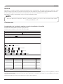
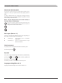
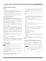
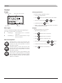
USER’S MANUAL MITSUBISHI HEAVY INDUSTRIES LTD. Air to Water Heat Pump Hydrolution (HM) HMA100V(M) / FDCW 71VNX, FDCW100VNX HMS140V / FDCW140VNX This heat pump complies with EMC Directive 2004/108/EC, LV Directive 2006/95/EC. CE marking is applicable to the area of 50 Hz power supply. PSA012B733A Table of Contents Safety percautions General Installation data Information about the installation Product information Features of Hydrolution Principle of operation Hydrolution Front panel, indoor unit How to use the front panel Menu types Quick movement Key lock Language setting Comfort setting heating General Operating status Changing the room temperature manually Default Heating curve setting Readjusting the default settings Heating system 2 Vacation set back Comfort setting with room sensor 2 5 5 6 6 6 7 8 8 8 8 8 Control Display Menu types Menu management Menu tree Main menus 1.0 [N] Hot water temp. 2.0 [N] Supply temp. 3.0 [N] Supply temp. 2 4.0 [N] Outdoor temp. 5.0 [N] Heat pump 6.0 [N] Room temperature 7.0 [N] Clock 8.0 [N] Other adjustments Checklist: Checks before commissioning 18 18 18 19 22 23 24 26 27 27 28 29 30 32 9 9 9 10 11 11 11 11 Comfort setting cooling General 12 Cooling operated from the outdoor sensor in operating mode AutoC 12 Comfort setting hot water Prioritizing Extra Hot Water Maintenance Checking the safety valves in indoor unit Pressure gauge in indoor unit Emptying the hot water heater Emptying the vessel Maintenance of outdoor unit Saving tips Dealing with comfort disruption Operating mode “Add. heat only” Emergency mode Alarm indications What happens in the event of an alarm? Recommended actions Resetting alarms 12 13 13 14 14 14 14 14 15 16 16 17 17 17 Safety precaution Safety precaution This applince is not intended for use by persons (including children) with reduced physical, sensory or mental capabilities, or lack of experience and knowledge, unless they have been given supervision or instruction concerning use of the appliance by a person responsible for their safety. Children should be supervised to ensure that they do not play with the appliance. When install the unit, be sure to check whether the selection of installation place, power supply specifications, usage limitation (piping length, height differences between indoor and outdoor units, power supply voltage and etc.) and installation spaces. l We recommend you to read this “SAFETY PRECAUTIONS”carefully before the installation work in order to gain full advantage of the functions of the unit and to avoid malfunction due to mishandling. l The precautions described below are divided into CAUTION .The matters with possibilities WARNING and leading to serious consequences such as death or serious personal injury due to erroneous handling are listed in the WARNING and the matters with possibilities leading to personal injury or damage of the unit due to erroneous handling including probability leading to serious consequences in some cases are listed in CAUTION . These are very important precautions for safety. Be sure to observe all of them without fail. l Be sure to confirm no anomaly on the equipment by commissioning after completed installation and explain the operating methods as well as the maintenance methods of this equipment to the user according to the owner’s manual. l Keep the installation manual together with owner’s manual at a place where any user can read at any time. Moreover if necessary, ask to hand them to a new user. WARNING Installation must be carried out by the qualified installer. If you install the system by yourself, it may cause serious trouble such as water leaks, electric shocks, fire and personal injury, as a result of a system malfunction. Install the system in full accordance with the instruction manual. Incorrect installation may cause bursts, personal injury, water leaks, electric shocks and fire. Use the original accessories and the specified components for installation. If parts other than those prescribed by us are used, It may cause water leaks, electric shocks, fire and personal injury. When installing in small rooms, take prevention measures not to exceed the density limit of refrigerant in the event of leakage. Consult the expert about prevention measures. If the density of refrigerant exceeds the limit in the event of leakage, lack of oxygen can occur, which can cause serious accidents. Ventilate the working area well in the event of refrigerant leakage during installation. If the refrigerant comes into contact with naked flames, poisonous gas is produced. After completed installation, check that no refrigerant leaks from the system. If refrigerant leaks into the room and comes into contact with an oven or other hot surface, poisonous gas is produced. Hang up the unit at the specified points with ropes which can support the weight in lifting for portage. And to avoid jolting out of alignment, be sure to hang up the unit at 4-point support. An improper manner of portage such as 3-point support can cause death or serious personal injury due to falling of the unit. Install the unit in a location with good support. Unsuitable installation locations can cause the unit to fall and cause material damage and personal injury. Ensure the unit is stable when installed, so that it can withstand earthquakes and strong winds. Unsuitable installation locations can cause the unit to fall and cause material damage and personal injury. Ensure that no air enters in the refrigerant circuit when the unit is installed and removed. If air enters in the refrigerant circuit, the pressure in the refrigerant circuit becomes too high, which can cause burst and personal injury. The electrical installation must be carried out by the qualified electrician in accordance with “the norm for electrical work” and “national wiring regulation”, and the system must be connected to the dedicated circuit. Power supply with insufficient capacity and incorrect function done by improper work can cause electric shocks and fire. Be sure to shut off the power before starting electrical work. Failure to shut off the power can cause electric shocks, unit failure or incorrect function of equipment. Be sure to use the cables conformed to safety standard and cable ampacity for power distribution work. Unconformable cables can cause electric leak, anomalous heat production or fire. Use the prescribed cables for electrical connection, tighten the cables securely in terminal block and relieve the cables correctly to prevent overloading the terminal blocks. Loose connections or cable mountings can cause anomalous heat production or fire. Arrange the wiring in the control box so that it cannot be pushed up further into the box. Install the service panel correctly. Incorrect installation may result in overheating and fire. Do not perform brazing work in the airtight room. It can cause lack of oxygen. Use the prescribed pipes, flare nuts and tools for R410A. Using existing parts (for R22 or R407C) can cause the unit failure and serious accidents due to burst of the refrigerant circuit. Tighten the flare nut by using double spanners and torque wrench according to prescribed method. Be sure not to tighten the flare nut too much. Loose flare connection or damage on the flare part by tightening with excess torque can cause burst or refrigerant leaks which may result in lack of oxygen. Do not open the service valves for liquid line and gas line until completed refrigerant piping work, air tightness test and evacuation. If the compressor is operated in state of opening service valves before completed connection of refrigerant piping work, air can be sucked into refrigerant circuit, which can cause bust or personal injury due to anomalously high pressure in the refrigerant. Do not put the drainage pipe directly into drainage channels where poisonous gases such as sulphide gas can occur. Poisonous gases will flow into the room through drainage pipe and seriously affect the user’s health and safety. Safety precaution Only use prescribed optional parts. The installation must be carried out by the qualified installer. If you install the system by yourself, it can cause serious trouble such as water leaks, electric shocks, fire. Do not run the unit with removed panels or protections Touching rotating equipments, hot surfaces or high voltage parts can cause personal injury due to entrapment, burn or electric shocks. Be sure to fix up the service panels. Incorrect fixing can cause electric shocks or fire due to intrusion of dust or water. Do not perform any repairs or modifications by yourself. Consult the dealer if the unit requires repair. If you repair or modify the unit, it can cause water leaks, electric shocks or fire. Do not perform any change of protective device itself or its setup condition. The forced operation by short-circuiting protective device of pressure switch and temperature controller or the use of non specified component can cause fire or burst. Be sure to switch off the power supply in the event of installation, inspection or servicing. If the power supply is not shut off, there is a risk of electric shocks, unit failure or personal injury due to the unexpected start of fan. Consult the dealer or an expert regarding removal of the unit. Incorrect installation can cause water leaks, electric shocks or fire. Stop the compressor before disconnecting refrigerant pipes in case of pump down operation. If disconnecting refrigerant pipes in state of opening service valves before compressor stopping, air can be sucked, which can cause burst or personal injury due to anomalously high pressure in the refrigerant circuit. CAUTION Carry out the electrical work for ground lead with care. Do not connect the ground lead to the gas line, water line, lightning conductor or telephone line’s ground lead. Incorrect grounding can cause unit faults such as electric shocks due to short-circuiting. Use the circuit breaker with sufficient breaking capacity. If the breaker does not have sufficient breaking capacity, it can cause the unit malfunction and fire. Earth leakage breaker must be installed. If the earth leakage breaker is not installed, it can cause electric shocks. Do not use any materials other than a fuse with the correct rating in the location where fuses are to be used. Connecting the circuit with copper wire or other metal thread can cause unit failure and fire. Do not install the unit near the location where leakage of combustible gases can occur. If leaked gases accumulate around the unit, it can cause fire. Do not install the unit where corrosive gas (such as sulfurous acid gas etc.) or combustible gas (such as thinner and petroleum gases) can accumulate or collect, or where volatile combustible substances are handled. Corrosive gas can cause corrosion of heat exchanger, breakage of plastic parts and etc. And combustible gas can cause fire. Secure a space for installation, inspection and maintenance specified in the manual. Insufficient space can result in accident such as personal injury due to falling from the installation place. When the outdoor unit is installed on a roof or a high place, provide permanent ladders and handrails along the access route and fences and handrails around the outdoor unit. If safety facilities are not provided, it can cause personal injury due to falling from the installation place. Do not use the indoor unit at the place where water splashes may occur such as in laundries. Since the indoor unit is not waterproof, it can cause electric shocks and fire. Do not install nor use the system close to the equipment that generates electromagnetic fields or high frequency harmonics. Equipment such as inverters, standby generators, medical high frequency equipments and telecommunication equipments can affect the system, and cause malfunctions and breakdowns. The system can also affect medical equipment and telecommunication equipment, and obstruct its function or cause jamming. Do not install the outdoor unit in a location where insects and small animals can inhabit. Insects and small animals can enter the electric parts and cause damage or fire. Instruct the user to keep the surroundings clean. Do not use the base flame for outdoor unit which is corroded or damaged due to long periods of operation. Using an old and damage base flame can cause the unit falling down and cause personal injury. Do not install the unit in the locations listed below. L ocations where carbon fiber, metal powder or any powder is floating. L ocations where any substances that can affect the unit such as sulphide gas, chloride gas, acid and alkaline can occur. V ehicles and ships. L ocations where cosmetic or special sprays are often used. L ocations with direct exposure of oil mist and steam such as kitchen and machine plant. L ocations where any machines which generate high frequency harmonics are used. L ocations with salty atmospheres such as coastlines. Locations with heavy snow (If installed, be sure to provide base flame and snow hood mentioned in the manual). L ocations where the unit is exposed to chimney smoke. L ocations at high altitude (more than 1000m high). L ocations with ammonic atmospheres. L ocations where heat radiation from other heat source can affect the unit. L ocations without good air circulation. L ocations with any obstacles which can prevent inlet and outlet air of the unit. L ocations where short circuit of air can occur (in case of multiple units installation). L ocations where strong air blows against the air outlet of outdoor unit. It can cause remarkable decrease in performance, corrosion and damage of components, malfunction and fire. Do not install the outdoor unit in the locations listed below. L ocations where discharged hot air or operating sound of the outdoor unit can bother neighborhood. L ocations where outlet air of the outdoor unit blows directly to plants. L ocations where vibration can be amplified and transmitted due to insufficient strength of structure. L ocations where vibration and operation sound generated by the outdoor unit can affect seriously. (on the wall or at the place near bed room) L ocations where an equipment affected by high harmonics is placed. (TV set or radio receiver is placed within 5m) L ocations where drainage cannot run off safely. It can affect surrounding environment and cause a claim. Safety precaution Do not install the remote controller at the direct sunlight. It can cause malfunction or deformation of the remote controller. Do not use the unit for special purposes such as storing foods, cooling precision instruments and preservation of animals, plants or art. It can cause the damage of the items. Take care when carrying the unit by hand. If the unit weights more than 20kg, it must be carried by two or more persons. Do not carry by the plastic straps, always use the carry handle when carrying the unit by hand. Use gloves to minimize the risk of cuts by the aluminum fins. Dispose of any packing materials correctly. Any remaining packing materials can cause personal injury as it contains nails and wood. And to avoid danger of suffocation, be sure to keep the plastic wrapper away from children and to dispose after tear it up. Pay attention not to damage the drain pan by weld spatter when welding work is done near the indoor unit. If weld spatter entered into the indoor unit during welding work, it can cause pin-hole in drain pan and result in water leakage. To prevent such damage, keep the indoor unit in its packing or cover it. Be sure to insulate the refrigerant pipes so as not to condense the ambient air moisture on them. Insufficient insulation can cause condensation, which can lead to moisture damage on the ceiling, floor, furniture and any other valuables. Be sure to perform air tightness test by pressurizing with nitrogen gas after completed refrigerant piping work. If the density of refrigerant exceeds the limit in the event of refrigerant leakage in the small room, lack of oxygen can occur, which can cause serious accidents. Do not touch any buttons with wet hands. It can cause electric shocks. Do not shut off the power supply immediately after stopping the operation. Wait at least 5 minutes, otherwise there is a risk of water leakage or breakdown. Do not control the system with main power switch. It can cause fire or water leakage. In addition, the fan can start unexpectedly, which can cause personal injury. Do not touch any refrigerant pipes with your hands when the system is in operation. During operation the refrigerant pipes become extremely hot or extremely cold depending the operating condition, and it can cause burn injury or frost injury. General General Hydrolution is a system for heating, cooling and producing hot water for small houses. The system consists of an outdoor nuit, which utilises the energy in the outdoor air and sends it to the indoor unit, which takes care of the regulation and heat distribution in the house. In order to get the greatest benefit from the system Hydrolution you should read through the User's Manual. Hydrolution is a quality system offering a long service life and reliable operation. NOTE Do not vent R410A into the atmosphere: R410A is a f luorinated greenhouse gas, covered by the K yoto Protocol with a Global Warming Potential(GWP) = 1975. Installation data Completed by the installation engineer when the installation is installed Installation data and installation check list on page 32 must be filled in by the installer in order for the warranty to apply. The Serial number, must always be stated in all correspondence with MHI. Indoor unit: _ _ _ _ _ _ _ _ _ _ _ _ _ _ Outdoor unit: _ _ _ _ _ _ _ _ _ _ _ Installation date Check list, page 32, filled in Installation engineers Heating Radiator Cooling Other Floor Floor Fan convector Fan convector External heat source Solar Gas Oil Accessories Tank heater Wood MH-RG 10 Not available Pellets ESV22 Electricity VCC22 ACK22 Settings Fill in the difference from default settings. Menu Number Menu Type Description Setting Date________Signed______________________________ This appliance is not intended for use by persons (including children) with reduced physical, sensory or mental capabilities, or lack of experience and knowledge, unless they have been given supervision or instruction concerning use of the appliance by a person responsible for their safety. Children should be supervised to ensure that they do not play with the appliance. Information about the installation Information about the installation Principle of operation Hydrolution 3 Product information Hydrolution is a complete modern heat pump system that offers effective technical energy saving and reduced carbon dioxide emissions. Heat production is safe and economical with integrated hot water heater, immersion heater, circulation pump and climate system in the indoor unit. The heat is retrieved from the outdoor air through outdoor unit, where the refrigerant circulated in a closed piping system transfers the heat from the heat source (outdoor air) to indoor unit. This eliminates the need for holes and coils in the ground. Features of Hydrolution ■Optimal annual heating factor thanks to the inverter controlled compressor. 1 2 4 Function Hydrolution is a system that can produce heating, hot water and cooling. The principle during heating can be simplified as follows: 1.The refrigerant in outdoor unit takes the heat from the outdoor air and is compressed to higher temperature by the compressor. 2.The hot refrigerant (now in gas state) is routed into indoor unit. ■Outdoor unit with compact dimensions. 3.The refrigerant releases the heat for further distribution in the system. ■Speed controlled system pump that supplies the heat pump with suitable system flow. 4.The refrigerant (now in liquid state) is routed back to outdoor unit and the process is repeated. ■Optimized operating costs. The speed of the compressor is adjusted according to the demand. By reversing the entire process, and thereby the refrigerant in outdoor unit takes the heat from the water and release the heat to the outdoor air, the heat pump can cool instead if necessary. ■Integrated coil water heater in indoor unit. ■Integrated clock for scheduling extra hot water and temperature lowering/increasing the supply water temperature. ■Prepared for control of two heating systems. ■Integrated active cooling function. ■Possible to connect external heat sources. Indoor unit determines when outdoor unit is to work and not to work, using the collated data from the temperature sensor. In the event of extra heat demands, indoor unit can connect additional heat source in the form of the internal immersion heater, or any connected external heat source. Front panel, indoor module Front panel, indoor unit Hot water symbol Addition. heat symbol If the electrical addition is connected “I” Electrical step 1 “II” Electrical step 2 “I II” Electrical step 1+2 “III” Electrical step 3 Hot water charging in progress. “A” Temporary Extra hot water operation in progress. “B” Time based Extra hot water operation in progress, e.g. periodic. Compressor symbol Circulation pump symbol - Compressor is operational “A” Heating mode “B” Cooling mode Operating status Button pressing (the change does not need to be confirmed with the enter button). - Current operating mode shown in display - Further button press changes operating mode. Press the enter button to return to the normal display mode. For information about the various operating modes, see the different sections regarding comfort settings. Extra hot water (XHW) Extra hot water operation starts with this button. The operation is cancelled when the button is pressed again. The change does not need to be confirmed with the Enter button. Menu 1.0 Pressing the button takes you directly to menu 1.0. Circulation pump in operation. With two circulation pumps (requires ESV 22 accessory), the operating pump is also indicated. Heating system symbol A I II III AB Heating in progress. I II 50.0°C 1.0 13.43 Description of current display parameter Information symbols 1.0 Menu number Key lock activated. Plus button - Scroll forward in the menu system. - Increase the value of the selected parameter See the section “Control – General” Minus button Offset heating curve - Turning clockwise (+) offsets the Heating curve. When the knob is turned menu 2.0 is shown on the display and the value for the calculated supply temperature changes. For details, see Default Heating curve setting. Switch 1 Normal mode All control functions connected. 0 Shutdown Emergency mode Only the circulation pump and electric heater (electrical step 2) are operational. - Scroll back in the menu system. - Reduce the value of the selected parameter See the section “Control – General” Enter button - Entering lower layer in the menu system. - Parameter change activated - Parameter change confirmed See the section “Control – General” Status lamp During normal operation, the status lamp lights green. In the event of an alarm, it lights red. Front panel, indoor module How to use the front panel All the most common settings are made from the panel such as comfort etc. that you expect from the heat pump system to fulfil. In order to make full use of it, certain basic settings must have been made (see page 10) and the installation in general is carried out according to the instructions. Menu 1.0 (the temperature in the water heater) is normally shown on the display. The plus and minus buttons and the enter button are used to scroll through the menu system as well as to change the set value in some menus. Menu types (Menu 8.1.1) Control is classified into different menu types depending on how “deep” into the controls you need to go. ■ Normal [N]:The settings you as a customer often need. ■ Extended [U]:Shows all detailed menus except the service menus. Quick movement To quickly return to the main menu from a sub menu, press the following button: Key lock A key lock can be activated in the main menus by simultaneously pressing the and the buttons. The key symbol will then be shown on the display. The same procedure is used to deactivate the key lock. Language setting (Menu 8.1.2) Language used in the display can be chosen in menu 8.1.2. Comfort setting heating Comfort setting heating General The indoor temperature depends on several factors. ■Sunlight and heat emissions from people and household machines are normally sufficient to keep the house warm during the warmer parts of the year. ■When it gets colder outside, the heating system must be started. The colder it is outside, the warmer radiators and under floor heating systems must be. Controlling heat production Normally, the heat pump heats the water (heating medium) to the temperature required at a certain outdoor temperature. This occurs automatically on the basis of the collected temperature values from the outdoor sensor and sensors on the lines to the radiators (supply water sensors). Extra accessories such as room sensors, can influence the temperature. In order to operate the system properly, the correct settings must be made on the heat pump first, see the section “Default Heating curve setting”. The outdoor sensor (mounted on an exterior wall of the house) senses variations in the outdoor temperature early on, sends the information to the heat pump control computer and heating operation is started. It does not have to be cold inside the house before the control system is activated. As soon as the temperature drops outside, the temperature of the water to the radiators (supply temp.) inside the house is increased automatically. The heat pumps flow temperature (menu 2.0) will hover around the theoretical required value, which is in brackets on the display. Temperature of the heating system The temperature of the heating system in relation to the outdoor temperature can be determined by you by selecting a heat curve and by using the “Offset heating curve” knob on the heat pump’s front panel. Operating status The “Operating mode” button is used to set the required operating mode. The change does not need to be confirmed with the enter button. The current operating mode is shown on the front panel display when the button is pressed and the mode changes when you continue to press the button. 1. “Auto” Indoor unit automatically selects the operating mode by taking the outdoor temperature into account. This means that the operating mode switches between "Heating" and “Hot water”. The circulation pump is permitted to operate when there is a need. 2. “AutoC”* Indoor unit selects operating mode automatically (cooling can also be selected now) by the outdoor temperature. This means that the operating mode switches between “Heating”, “Cooling” and “Hot water”. The circulation pump is permitted to operate when there is a need. 3. Heating Only heating and hot water mode. The circulation pump is in operation the entire time. Electirc heater is energized if necessary. 4. Cooling* Heat pump is used for cooling only if electric heater use is allowed. Otherwise, it is used for both cooling and hot water. The circulation pump is in operation the entire time. 5. Hot water Only hot water is produced. Only the compressor is operational. 6. Add. Heat only Heat pump is not operational. The function is activated/ deactivated by pressing in the “operating mode button” for 7 seconds. * To use the cooling functions, the system must be designed to withstand low temperatures and cooling must be activated in menu 9.3.3. Changing the room temperature manually If you want to temporarily or permanently increase or lower the indoor temperature, turn the “Offset heating curve” knob clockwise to increase or anticlockwise to lower. One line approximately represents 1 degree change in room temperature. NOTE An increase in the room temperature may be inhibited by the radiator or underfloor heating thermostats, if so these must be set at 0. The display returns to the normal display mode once the enter button is pressed. The electric heater is only used for anti-freeze if it is deactivated in the menu system for all operating modes. There are different operating modes to choose: Comfort setting heating Default Heating curve setting Setting with diagrams The basic heating is set using menu 2.1.2 and with the “Heating curve offset” knob. The diagram shows the relation between the outdoor temperature in the area and the target supply water temperature of the heating system. This is set under menu 2.1.2, “Heating curve”. Limitations, which are not in the diagrams, can be set in the control system’s permitted min and max temperatures. (See menu 2.1.4 and 2.3 as well as 3.3 and 3.4) If the room temperature does not reach the target, readjustment may be necessary. If you do not know the correct settings, use the basic data from the automatic heating control system diagram on the right. Heating curve offset -2 9 Offset heating curve Heating curve offset for system 2 can be made in menu 3.1 NOTE Wait one day between settings so as to stabilise the temperatures. Supply temperature Menu 2.1.2 Heating curve FRAMLEDNINGSTEMPERATUR HEATING CURVE VÄRMEKURVA Heating curve 2.1.2 C 70 15 14 13 12 11 10 9 8 60 7 6 50 5 40 4 3 30 2 +5 1 10 0 - 10 - 20 - 40 - 30 Outdoor temperature FÖRSKJUTNING VÄRMEKURVA (-2) OFFSET HEAT CURVE -5 C UTETEMPERATUR Heating curve offset 0 Supply temperature FRAMLEDNINGSTEMPERATUR HEATING CURVE VÄRMEKURVA C 70 15 14 13 12 11 10 9 8 60 7 6 50 5 4 40 3 2 30 1 +5 10 0 - 10 - 20 - 30 FÖRSKJUTNING Outdoor temperature VÄRMEKURVA (0) OFFSET HEAT CURVE -5 - 40 C UTETEMPERATUR Heating curve offset +2 Supply temperature FRAMLEDNINGSTEMPERATUR HEATING CURVE VÄRMEKURVA C 70 15 14 13 12 11 10 8 7 60 6 5 50 4 3 40 2 30 1 +5 10 -5 0 - 10 - 20 FÖRSKJUTNING Outdoor temperature VÄRMEKURVA (+2) OFFSET HEAT CURVE 10 9 - 30 - 40 C UTETEMPERATUR Comfort setting heating Readjusting the default settings Comfort setting with room sensor If the room temperature does not reach the target, readjustment may be necessary. If MH-RG10 is installed, operation mode is chosen not only by outdoor temperature but also by room temperature. Cold weather conditions Upper limit of the outdoor temperature to operate in Heating mode can be set in menu 8.2.3 Stop temp Heating. ■When the room temperature is too high, the “Heating curve” value is decreased in menu 2.1.2 by one increment. Warm weather conditions ■If the room temperature is low, increase the “Heating curve offset” setting by one step clockwise. ■If the room temperature is high, reduce the “Heating curve offset” setting by one step anti-clockwise. Heating system 2 If the heating system has two different type of emitter like radiator and under floor heating, it is possible to set two different calculated supply temperature. System 1 for higher supply temperature can be set in menu 2.1.0, and system 2 for lower supply temperature can be set in menu 3.0. Vacation set back Lower limit of the outdoor temperature to operate in Cooling mode can be set in menu 8.2.4 Start temp Cooling. Target room temperature can be adjusted by turning the knob on MH-RG10, and it is displayed in menu 6.3. For details, see instruction manual for MH-RG10. The below figure shows an example of mode transition. Room temperature ■When the room temperature is too low, the “Heating curve” value is increased in menu 2.1.2 by one increment. Target room temp (6.3) Heating Stop temp Heating (8.2.3) Start temp Cooling (8.2.4) Outdoor temperature Mode transition (in case AutoC is chosen) LEK When you are away from home for a long time, it is possible to set the target supply water temperature for heating lower than usual to save energy consumption. Also, it is possible to cancel hot water operation during the period. For details, see menu 7.5.0 Vacation set back. Cooling Hot water production Knob MH-RG10 11 Comfort setting cooling / Comfort setting hot water Comfort setting cooling Comfort setting hot water General The integrated water heater is a coil model and is heated by circulating water, which is heated by the heat pump. In the default setting, cooling operation is not allowed. In order to activate, change the setting on the menu 9.3.3 Cooling system to “On”. NOTE The climate system must manage cooling operation. Setting must be made by the installer when commissioning the system. Settings must be made by the installer when commissioning the system. If a room sensor is connected, it starts and stops cooling based on both the room and the outdoor temperature. The lowest calculated supply water temperature is set in menu 2.2.4. Cooling operated from the outdoor sensor in operating mode AutoC If the cooling system is set to “On” in menu 9.3.3 and the outdoor temperature is greater or equivalent to the set start temperature for cooling in menu 8.2.4, cooling starts. Cooling stops when the outdoor temperature drops below the set value minus the set value in menu 8.2.5. The calculated supply water temperature is determined from the selected cooling curve in menu 2.2.2 and the offset for cooling curve, menu 2.2.1. Limitations, which are not in the diagram, are included in the control system’s permitted min temperature. Calculated supply water temperature framledningstemp. C 20 15 k=1 10 k=2 5 k=3 0 0 12 20 30 Outdoor temperature 40 eUtetem C During “normal” consumption it is enough to run the heat pump to supply the different tapping points of the house with hot water. The temperature of the hot water in the water heater then varies between the set values. Under section 1.0 [N] Hot water temp. on page 23 there is a complete description of menu settings for hot water temperatures. Prioritizing When the water temperature in the tank drops, heat pump operation shifts to hot water production. In case there is demand for both hot water and heating/cooling for long time, operation mode is periodically switched between hot water and heating/cooling. For details, see menu 1.0 Hot water temp and 8.5.0 Period settings. Comfort setting hot water / Maintenance Maintenance Extra Hot Water In all “Extra hot water” functions, the temperature of the hot water increases temporarily. The temperature is first increased to an adjustable level by the compressor (menu 1.5) and then the electric heater is energized until the water temperature reaches the stop temperature (menu 1.4). Temporary “Extra hot water” is activated manually, whilst time based extra hot water is activated using the settings made in the control computer. When: Hydrolution requires minimal maintenance after commissioning. Hydrolution contains many components and is why monitoring functions are integrated to help you. If something abnormal occurs, a message appears about malfunctions in the form of different “alarm” texts in display. Checking the safety valves in indoor unit ■“A” appears above the is active. icon, temporary extra hot water Indoor unit has been equipped with a safety valve for the water heater as well as a safety valve for the climate system by the installer. ■“B” appears above the is active. icon, time based extra hot water The climate system’s safety valve HMA100V(M) BP5 FL2 NOTE “ Extra hot water” usually means that the electric heater is activated regardless of Allow add heat setting (menu 8.2.1) and therefore increases the electrical consumption. MT300(HMS140V) FL2 “Extra hot water” can be activated in three different ways: 1. Periodic time based extra hot water Interval between extra hot water operation is selected in menu 1.7. Menu 1.8 shows when the next extra hot water operation is due. The increased temperature is maintained by the electric heater for one hour. 2. Schedule time based extra hot water The start and stop times for the day of the week when the extra hot water operation is required are set in the sub menus to menu 7.4.0. The increased temperature is maintained by the electric heater for the selected period. 3. Temporary extra hot water Extra hot water operation starts when Extra hot water button is pressed, and it is kept for 3 hours. The operation is cancelled when the button is pressed again during the period. The increased temperature is maintained by the electric heater until the period of time has expired. BP5 The climate system’s safety valve (FL2) must be completely sealed. Checks must be carried out regularly as follows: ■Open the valve. ■Check that water flows through the valve. If this does not happen, replace the safety valve. ■Close the valve again. ■The heating system may need to be refilled after checking the safety valve, see the section “Filling the heating system”. 13 Maintenance Hot water heater safety valve The water heater’s safety valve sometimes releases a little water after hot water usage. This is because the cold water, which enters the heater to replace the hot water, expands when heated causing the pressure to rise and the safety valve to open. Also check the water heater safety valve regularly. The appearance and location of the safety valve differs between different installations. Contact your installer for information. Pressure gauge in indoor unit The working range of the heating system is normally 0.5 – 1.5 bar when the system is closed. Check this on the pressure gauge (BP5). Emptying the hot water heater The water heater is of the coil type and is drained using the siphon principle. This can be done either via the drain valve on the incoming cold water pipe or by inserting a hose into the cold water connection. Emptying the vessel Contact your installer if the vessel in indoor unit needs emptying. Maintenance of outdoor unit Outdoor unit is equipped with control and monitoring equipment, however some exterior maintenance is still necessary. Make regular checks throughout the year that the inlet grille is not clogged by leaves, snow or anything else. During the cold months of the year, check to make sure that there isn’t a build up of ice or frost under outdoor unit. Strong wind combined with heavy snowfall can block the intake and exhaust air grilles. Make sure that there is no snow on the grilles. Also check that the condensation water drain under outdoor unit is not blocked. If necessary the outer casing can be cleaned using a damp cloth. Care must be exercised so that the heat pump is not scratched when cleaning. Avoid spraying water into the grilles or the sides so that water penetrates into outdoor unit. Prevent outdoor unit coming into contact with alkaline cleaning agents. ! WARNING! Rotating fan Saving tips Your Hydrolution produces heat and hot water according to your needs. It also attempts to carry out all requirements with all available “aids” from the control settings made. 14 The indoor temperature is naturally affected by the energy consumption. Therefore, take care not to set a temperature higher than necessary. Other known factors that affect the energy consumption are, for example, hot water consumption and the insulation level of the house, as well as the level of comfort you require. Also remember: ■Open the thermostat valves completely (except in the rooms that are to be kept cooler for various reasons, e.g. bedrooms). Thermostat valves in the radiators and floor loops can negatively affect the energy consumption. They slow the flow in the heating system, which the heat pump wants to compensate with increased temperatures. It then works harder and consumes more electrical energy. Dealing with comfort disruption Dealing with comfort disruption Use the following list to find and remedy any heating or hot water problems. Symptom Low hot water temperature or a lack of hot water Low room temperature. Cause Circuit or main MCB tripped. Action Check and replace blown fuses. Heat pump and immersion heater do not heat. Check and replace any blown circuit and main fuses. Possible earth circuit-breaker tripped. Reset the earth circuit-breaker, if the earth circuit-breaker trips repeatedly, call an electrician. Switch (SF1) set to mode 0. Set the switch to 1. Large hot water demand. Wait a few hours and check if the hot water temperature rises. Too low start temperature setting on the control system. Adjust the start temperature setting in menu 1.2. Possible earth circuit-breaker tripped. Reset the earth circuit-breaker, if the earth circuit-breaker trips repeatedly, call an electrician. Heat pump and immersion heater do not heat. Check and replace any blown circuit and main fuses. Incorrect setting of “Heating curve, offset” and/or “Cooling curve, offset”. Adjust the settings. Check menu 2 .1.1, 2.1.2 for heating system 1 3.1, 3.2 for heating system 2 2.1.1, 2.2.2 for cooling system Stop temp heating setting is too low. Adjust the setting. Check menu 8.2.3 Circuit or main MCB tripped. Check and replace blown fuses. Heat pump in incorrect operating mode “Hot Change operating mode to “Auto” or “ Auwater” or “Cooling”. toC”. High room temperature. The compressor does not start. Panel gone out. The current limiter has restricted the current because many power consumers are being used in the property. Switch off one/several of the power consumers. Incorrect setting of “Heating curve, offset” and/or “Cooling curve, offset”. Adjust the settings. Check menu 2 .1.1, 2.1.2 for heating system 1 3.1, 3.2 for heating system 2 2.1.1, 2.2.2 for cooling system Heat pump in incorrect operating mode. Change operating mode to “AutoC”. Start temp cooling setting is too high. Heat load is too high. Adjust the setting. Check menu 8.2.4. Remove the excess heat load. Minimum time between compressor starts alternatively time after power switch on not being achieved. Wait 30 minutes and check if the compressor starts. Alarm tripped. See section “Alarms”. Alarm cannot be reset. Activate operating mode “Add. heat only”. Check and replace any blown circuit andmain fuses. Check that the circuit breaker to the indoor unit is not off. Set switch (SF1) to standby “ ”. 15 Dealing with comfort disruption The phenomena mentioned below is not malfunction. The air conditioning system sounds as if water is draining from it. Sounds of rustling or gurgling may be heard from a stopped indoor unit. The air conditioning system cannot start operating again immediately after stopping. The outdoor unit discharges water or steam during heating operation. The outdoor unit fan is not running even when the system is in operation. Sounds of rustling or gurgling may be heard when the operation is started, when the compressor is activated/deactivated during operation, or when the operation is stopped. These are the sounds of the refrigerant flowing through the system. These sounds can be heard when the air conditioning system is performing automatic control. Outdoor unit does not restart during the first 3 minutes after stopping operation. This is because a circuit for protecting the compressor is activated (the fan is operating during this period). Water or steam is discharge during defrosting operation which removes frost built up on the surface of the heat exchanger in the outdoor unit in heating mode. The fan speed is automatically controlled according to the ambient temperature. It may be stopped in high ambient temperature in case of heating, and in low ambient temperature in case of cooling. Also, the fan is stopped during defrosting operation. REQUESTS Hissing sounds are heard when the operation is stopped or during defrost operation. The fan will suddenly begin to operate even if it is stopped. Do not insert finger and/or stick. These sounds are generated when the refrigerant valve inside the air conditioning system is activated. Operating mode “Add. heat only” In the event of malfunctions that cause a low indoor temperature, you can normally activate “Add. heat only” in indoor unit, which means that heating only occurs with the immersion heater. Activate the mode by holding in the operating mode button for 7 seconds. Note that this is only a temporary solution, as heating with the immersion heater does not make any savings. Emergency mode Emergency mode is activated by setting the switch to “ ”. It is used when the control system and thereby operating mode “Add. heat only” do not function as they should. Emergency mode is activated by setting switch (SF1) to “ ”. The following applies in emergency mode: ■The front panel is not lit and the control computer in indoor unit is not connected. ■Outdoor unit is off and only the circulation pump and immersion heater in indoor unit are active. ■An electrical step of 4 kW is connected. The immersion heater is controlled by a separate thermostat (BT30). ■The automatic heating control system is not operational, so manual shunt operation is required. Call installer. 16 Alarm indications Alarm indications Different types of alarms There are many monitoring functions integrated in Hydrolution. To alert you to any malfunctions, the control computer transmits alarm signals that can be read from the front panel display. What happens in the event of an alarm? ■The background lighting in the display starts flashing and the status lamp lights red. ■Some alarms change operating mode to “Add. heat only.” and reduce the supply temperature to the minimum permitted temperature to notify you that something is wrong. ■Alarms with automatic reset (do not need to be acknowledged when the cause has disappeared). ■Existing alarms that require corrective action by you or the installer. Recommended actions 1. R ead off which alarm has occurred from the heat pump’s display. 2. As a customer you can rectify certain alarms. See the table below for relevant actions. If the alarm is not rectified, or is not included in the table, contact your installer. Alarm text on the display Alarm description Check/remedy before installers/service technicians are called LP-ALARM Tripped low pressure sensor. Check that the thermostats for the radiators/ under-floor systems are not closed. HP-ALARM Tripped high pressure sensor. Check that the thermostats for the radiators/ under-floor systems are not closed. OU power failure / OU Com. error Outdoor unit not powered / Communication cut Check that any circuit breakers to the outdoor unit are not off. Display not lit Check and replace any blown circuit and main fuses. Check that the circuit breaker to the indoor unit is not off. Check that the switch (SF1) is in normal position (1). Resetting alarms No harm in resetting an alarm. If the cause of the alarm remains, the alarm recurs. ■When an alarm has been triggered, it can be reset by switching indoor unit off and on using the switch (SF1). ■When the alarm cannot be reset using the switch (SF1), the operating mode, “Add. heat only”, can be activated to resume a normal temperature level in the house. This is most easily carried out by holding the “Operating mode” button in for 7 seconds. NOTE Recurring alarms mean that there is a fault in the installation. Contact your installer! 17 Control Control Display Changing parameters Operating symbols A I II III Value of the current parameter AB I II 50.0°C 1.0 13.43 Menu name Menu number Key lock Clock Menu types Control is classified into different menu types depending on how “deep” into the controls you need to go. In order to change a parameter (value): 1. Access the required menu. 2. Press 3. Increase or decrease using 4. Confirm by pressing 5.Menu 1.0 is automatically displayed again 30 minutes after the last button is pressed. button, the numerical value starts to flash. or buttons. button. Example Changing the heating curve, menu 2.1. 1. The starting point is menu 1.0. ■ Normal [N]:The settings you as a customer often need. 2. Press button to move to menu 2.0. ■ Extended [U]:Shows all detailed menus except the service menus. 3. Press button to move to menu 2.1. 4. Press button to change the value. The Plus button is used to move forward to the next menu on the current menu level and to increase the value of the parameter in menus where this is possible. 5.Change the value by pressing 6.Confirm the selected value by pressing The Minus button is used to move back to the previous menu on the current menu level and to decrease the value of the parameter in menus where this is possible. 7. Press Menu management The Enter button is used to select submenus of the current menu, to permit parameters to be changed and to confirm any changes to parameters. When the menu number ends with a zero this indicates that there is a submenu. 18 or button to access menu 1.0. buttons. button. Control Menu tree 1.0 [N] Hot water temp. 1.1 [N] Max HW/Peroid time 1.2 [N] Start temperature HW 1.3 [N] Stop temperature HW 1.4 [U] Stop temperature XHW 1.5 [U] Heat pump stop XHW 1.6 [U] Max heat p. time XHW 1.7 [U] Interval XHW 1.8 [U] Next XHW action 1.9 [U] HW run time 1.12 [N] Return 2.0 [N] Supply temp. 2.1.0 [N] Heating settings 2.1.1 [N] Offset heating/Total 2.1.2 [N] Heating curve 2.1.3.0 [U] Own heating curve 2.1.3.1 [U] Supply temp.at +20 2.1.3.2 [U] Supply temp.at -20 2.1.3.3 [U] Buckling temperature 2.1.3.4 [U] Supply t. at buckl. 2.1.3.5 [U] Return 2.1.4 [U] Min supply heating 2.1.5 [U] Circ-pump speed heat 2.1.6 [N] Return 2.2.0 [N] Cooling settings 2.2.1 [N] Offset cooling/Total 2.2.2 [N] Cooling curve 2.2.3.0 [U] Own cooling curve 2.2.3.1 [U] Supply temp.at +20 2.2.3.2 [U] Supply temp.at +40 2.2.3.3 [U] Return 2.2.4 [U] Min supply cooling 2.2.5 [U] Circ-pump speed cool 2.2.6 [N] Return 2.3 [U] Max supply temp. 2.4 [U] External adjustment 2.5 [U] Supply/Return temp. 2.6 [U] Degree minutes 2.7 [N] Return 19 Control 3.0 [N] Supply temp. 2 4.0 [N] Outdoor temp. 3.1 [N] Offset heating/Tot 2 4.1 [N] Outdoor avg. temp. 3.2 [N] Heating curve 2 4.2 [U] Outdoor filter time 3.3 [U] Min supply temp. 2 4.3 [U] Outdoor avg. 1min. 3.4 [U] Max supply temp. 2 4.4 [N] Return 3.5 [U] External adjust. 2 3.6.0 [U] Own heating curve 2 3.6.1 [U] Supply temp.at +20 3.6.2 [U] Supply temp.at -20 3.6.3 [U] Buckling temperature 3.6.4 [U] Supply t. at buckl 3.6.5 [U] Return 3.7 [U] Supply/Return temp 2 3.8 [N] Return 5.0 [N] Heat pump 6.0 [N] Room temperature* 5.1 [N] Number of starts 6.1 [U] Room compensation 5.2 [N] Run time compressor 6.2 [U] Heating system 5.3 [U] Time to start 6.3 [N] Room temp. setpoint 5.4 [U] Outdoor temp. Tho-A 6.4 [U] Room temp avg. 1min 5.5 [U] Heat Ex Tho-R1 6.5 [U] Room integrator time 5.6 [U] Heat Ex Tho-R2 6.6 [N] Return 5.7 [U] Suction temp. Tho-S *Requires accessory and activation in menu 9.3.6. 5.8 [U] Hot gas Tho-D 5.9 [U] Liquid line temp. 5.10 [U] Condensor out / max 5.11 [U] HP 5.12 [U] LPLPT 5.13 [U] Fan speed 5.14.0 [U] CompFreq act/set 5.14.1 [U] OU current CT 5.14.2 [U] Inverter temp Tho-IP 5.14.3 [U] Return 5.16 [N] Return 20 Control 7.0 [N] Clock 8.0 [N] Other adjustments 7.1 [N] Date 8.1.0 [N] Display settings 7.2 [N] Time 7.3.0 [U] Temp set back 8.1.2 [N] Language 7.3.1 [U] Set back time 8.1.3 [N] Display contrast 7.3.2 [U] Set back temp +/- 8.1.4 [N] Light intensity 7.3.3 [U] Heating system 8.1.5 [N] Return 7.3.4 [U] Return 7.4.0 [U] Extra hot water 8.2.0 [N] Op. mode settings 8.2.1 [N] Allow add. heat 7.4.1 [U] XHW Monday 8.2.2 [N] Add. heat only 7.4.2 [U] XHW Tuesday 8.2.3 [U] Stop temp. heating 7.4.3 [U] XHW Wednesday 8.2.4 [U] Start temp. cooling 7.4.4 [U] XHW Thursday 8.2.5 [U] Hysteresis 7.4.5 [U] XHW Friday 8.2.6 [N] Return 7.4.6 [U] XHW Saturday 7.4.7 [U] XHW Sunday 8.3.0 [U] Current limiter 8.3.1 [U] Fuse size 8.3.2 [U] Max. electric power 7.4.8 [U] Return 7.5.0 [U] Vacation set back 8.1.1 [N] Menu type 8.3.3 [U] Current phase 1 7.5.1 [U] Vacation begins 8.3.4 [U] Current phase 2 7.5.2 [U] Vacation ends 8.3.5 [U] Current phase 3 7.5.3 [U] Heating system 8.3.6 [U] Transform. ratio EBV 7.5.4 [U] Offset heating curve 8.3.7 [U] Return 7.5.5 [U] HW off 7.5.6 [U] Return 8.5.0 [U] Period settings 8.5.1 [U] Period time 8.5.2 [U] Max time for HW 7.6 [N] Return 8.5.3 [U] Return 8.6 [N] Return 21 Control Main menus Menu 1.0 [N] Hot water temp. The current hot water temperature in the vessel is shown here. Figure on left shows the one in the middle and right one in brackets shows the one on the bottom. Menu 2.0 [N] Supply temp. The current supply temperature for the heating system is shown here with the calculated supply temperature in brackets. Menu 3.0 [N] Supply temp. 2 The current supply temperature for heating system 2 is shown here with the calculated supply temperature in brackets. Menu 4.0 [N] Outdoor temp. The current outdoor air temperature is displayed here. Menu 5.0 [N] Heat pump The outdoor operation data are shown in the sub-menus to this menu. The following text appears in the display. Text Means Off Shown when there is no compressor demand and none of the following apply. On Shown during normal operation with the compressor. Initiates Shown while the compressor is running. Com. problem Shown in the event of temporary communication problems. Defrosting Shown during defrost. Oil return Shown when the compressor is rotated to be lubricated. Protection Shown when the compressor is in some form of protection or during a start delay of 30 minutes. Shutdown Shown in the event of an alarm, tariff B or Operating mode Addition only. Stopped Shown when the outdoor temperature is outside the compressor’s working range (too high or too low temperature). Menu 6.0 [N] Room temperature The room temperature is shown here and the set room temperature in brackets. The factor for the room sensor and heating system to control are set in the sub-menus to this menu. Menu 7.0 [N] Clock The date and time are set in the submenus of this menu. Different temperature reductions and increases at selected times are also set from this menu. Menu 8.0 [N] Other adjustments The menu type, language, operating mode settings and load monitor reading are set in the sub-menus to this menu. 22 NOTE! These settings should only be made by persons with the necessary expertise. [N] Normal, covers the normal user’s needs. [U] Extended, shows all menus except the service menus. Control 1.0 [N] Hot water temp. Menu 1.1 [N] Max HW/Period time Menu 1.12 [N] Return Return to menu 1.0. The time of the hot water period and the time for the whole period are shown here. Whole period is shown in brackets. Shown for both hot water charging and heating when necessary: Time for Heating (Max.) when heating is in progress. Time for Hot water (Max.) if hot water charging is in progress. Menu 1.2 [N] Start temperature HW The temperature when the heat pump starts hot water charging is set here. Setting range: 25 – 55 °C Menu 1.3 [N] Stop temperature HW The temperature when the heat pump stops hot water charging is set here. Setting range: 30 – 60 °C Menu 1.4 [U] Stop temperature XHW The desired temperature during extra hot water is set here. Setting range: 40 – 65 °C Menu 1.5 [U] Heat pump stop XHW The desired stop temperature during extra hot water for the heat pump is set here. Setting range: 40 – 60 °C Menu 1.6 [U] Max heat p. time XHW Here you select the maximum amount of time the heat pump can charge hot water for during extra hot water. Setting range: 0 – 60 min Menu 1.7 [U] Interval XHW Periodic time based extra hot water is selected here. Extra hot water is shut off at the value “Off”. Extra hot water is started when the value is confirmed. Setting range: 0 – 90 days Menu 1.8 [U] Next XHW action Time to the next periodic Extra hot water operation is shown here. Menu 1.9 [U] HW run time Shows how long hot water charging with the compressor has been in progress (accumulated). 23 Control 2.0 [N] Supply temp. Menu 2.1.4 [U] Min supply heating Menu 2.1.0 [N] Heating settings The set minimum level for the supply temperature to the heating system is shown here. Heating settings are made in the sub-menus for this menu. Menu 2.1.1 [N] Offset heating/Total The selected heating curve offset is shown here. The total offset of the heat curve is also shown here. It includeschedule, outer compensation and any room control. Note! The value is changed using the “Heating curve offset” knob. The calculated flow temperature never drops below the set level irrespective of the outdoor temperature, heating curve or its offset heating curve. Setting range: 20 – 65 °C Menu 2.1.5 [U] Circ-pump speed heat Setting range: -10 – 10 The speed of the circulation pump during space heating is selected here. Menu 2.1.2 [N] Heating curve Setting range: 1 – 100 The selected heating curve is shown here. At value 0, the function “Own heat curve” is activated, see menu 2.1.3.0. Menu 2.1.6 [N] Return Setting range: 0 – 20 Return to menu 2.1.0. Menu 2.2.0 [N] Cooling settings Menu 2.1.3.0 [U] Own heating curve Here you can select your own curve definition. This is an individual linear curve with one break point. You select a break point and the associated temperatures. Cooling settings are made in the sub-menus for this menu. Menu 2.2.1 [N] Offset cooling/Total The selected cooling curve offset is changed here. Note! The “Heating curve” in menu 2.1.2 must be set to 0 to activate this function. The total offset of the cooling curve is also shown here. It includes schedule, outer compensation and any room control. Menu 2.1.3.1 [U] Supply temp.at +20 Setting range: -10 – 10 The supply temperature at an outdoor air temperature of +20 °C is selected here. Menu 2.2.2 [N] Cooling curve Setting range: 0 – 80* °C The selected cooling curve is shown here. At value 0, the function “Own cooling curve” is activated, see menu 2.2.3.0. * Limited by menu 2.3 Max supply temp. Setting range: 0 – 3 Menu 2.1.3.2 [U] Supply temp.at -20 The supply temperature at an outdoor air temperature of -20 °C is selected here. Menu 2.2.3.0 [U] Own cooling curve Setting range: 0 – 80* °C Note! The cooling curve in menu 2.2.2 must be set to 0 to activate this function. * Limited by menu 2.3 Max supply temp. Menu 2.1.3.3 [U] Buckling temperature Here you select at what outside air temperature the break point shall occur. Here you can select your own curve definition. Menu 2.2.3.1 [U] Supply temp.at +20 The supply temperature at an outdoor air temperature of +20 °C is selected here. Setting range: 0 – 25* °C Setting range: -15 – 15 °C * Limited by menu 2.2.4 Min supply cooling. Menu 2.1.3.4 [U] Supply t. at buckl. Menu 2.2.3.2 [U] Supply temp.at +40 You set the calculated supply temperature for the break point here. The supply temperature at an outdoor air temperature of +40 °C is selected here. Setting range: 0 – 80* °C Setting range: 0 – 25* °C * Limited by menu 2.3 Max supply temp. * Limited by menu 2.2.4 Min supply cooling. Menu 2.1.3.5 [U] Return Menu 2.2.3.3 [U] Return Return to menu 2.1.3.0. Return to menu 2.2.3.0. 24 Control Menu 2.2.4 [N] Min supply cooling The set minimum level for the supply temperature to the cooling system is shown here. The calculated flow temperature never drops below the set level irrespective of the outdoor temperature, cooling curve or its offset. Setting range: 7 – 25 °C (18 – 25 °C for HMS140V) Menu 2.2.5 [N] Circ-pump speed cool The speed of the circulation pump during cooling is selected here. Setting range: 1 – 100 Menu 2.2.6 [N] Return Return to menu 2.2.0. Menu 2.3 [U] Max supply temp. The set maximum level for the supply temperature to the heating system is shown here. The calculated flow temperature never exceeds the set level irrespective of the outdoor temperature, heating curve or offset heating curve. Setting range: 25 – 65 °C Menu 2.4 [U] External adjustment Connecting an external contact, for example, a room thermostat (accessory) or a timer allows you to temporarily or periodically raise or lower the room temperature. When the external contact is closed, the heating curve offset or cooling curve offset is changed by the number of steps shown here. If room control is active there is a degree change to the set room temperature. Setting range: -10 – 10 Menu 2.5 [U] Supply/Return temp. The current supply and return line temperatures are shown here. Return temperature is shown in brackets. Menu 2.6 [U] Degree minutes Current value for number of degree-minutes. In addition, this value can be changed to accelerate the start of heating production or cooling. Setting range: -32000 – 32000 Menu 2.7 [N] Return Return to menu 2.0. 25 Control 3.0 [N] Supply temp. 2 Menu 3.6.1 [U] Supply temp.at +20 Menu 3.1 [N] Offset heating/Tot 2 The supply temperature at an outdoor air temperature of +20 °C is selected here. The heating curve offset 2 is selected here. The total offset of heat curve 2 is also shown here. It includes schedule, outer compensation and any room control. Setting range: -10 – 10 Menu 3.2 [N] Heating curve 2 The selected heating curve is shown here. At value 0, the function “Own heat curve 2” is activated, see menu 3.6.0. Setting range: 0 – 20 Menu 3.3 [U] Min supply temp. 2 The set minimum level for the supply temperature for heating system 2 is shown here. The calculated flow temperature never drops below the set level irrespective of the outdoor temperature, heating curve or its offset. Setting range: 0 – 80* °C * Limited by menu 3.4 Max supply temp. 2. Menu 3.6.2 [U] Supply temp.at -20 The supply temperature at an outdoor air temperature of -20 °C is selected here. Setting range: 0 – 80* °C * Limited by menu 3.4 Max supply temp. 2. Menu 3.6.3 [U] Buckling temperature Here you select at what outside air temperature the break point shall occur. Setting range: -15 – 15 °C Menu 3.6.4 [U] Supply t. at buckl Setting range: 10 – 65 °C You set the calculated supply temperature for the break point here. Menu 3.4 [U] Max supply temp. 2 Setting range: 0 – 80* °C The set maximum level for the supply temperature for heating system 2 is shown here. * Limited by menu 3.4 Max supply temp. 2. The calculated flow temperature never exceeds the set level irrespective of the outdoor temperature, heating curve or its offset. Setting range: 10 – 65 °C Menu 3.5 [U] External adjust. 2 Connecting an external contact, for example, a room thermostat (accessory) or a timer allows you to temporarily or periodically raise or lower the room temperature. When the external contact is closed, the heating curve offset or the cooling curve offset is changed by the number of steps shown here. If room control is active there is a degree change to the set room temperature. Setting range: -10 – 10 Menu 3.6.0 [U] Own heating curve 2 Here you can select your own curve definition. This is an individual linear curve with one break point. You select a break point and the associated temperatures. Note! The heating curve in menu 3.2 must be set to 0 to activate this function. 26 Menu 3.6.5 [U] Return Return to menu 3.6.0. Menu 3.7 [U] Supply/Return temp 2 The present supply and return temperatures for heating system 2 are shown here. Return temperature is shown in brackets. Menu 3.8 [N] Return Return to menu 3.0. Control 4.0 [N] Outdoor temp. 5.0 [N] Heat pump Menu 4.1 [N] Outdoor avg. temp. Menu 5.1 [N] Number of starts This menu shows the average outdoor temperature according to the set value in menu 4.2 (factory setting: 24h). The accumulated number of starts with the compressor in outdoor unit is shown here. Menu 4.2 [U] Outdoor filter time Menu 5.2 [N] Run time compressor Here you select during how long the average temperature in menu 4.1 is calculated. Setting range: 1 min, 10 min, 1h, 2h, 4h, 6h, 12h, 24h Menu 4.3 [U] Outdoor avg. 1min. Shows the average outdoor temperature over the last minute. The accumulated time that the compressor has been used in outdoor unit is shown here. Menu 5.3 [U] Time to start Time until the compressor start in outdoor unit is shown in this menu. Menu 5.4 [U] Outdoor temp. Tho-A Menu 4.4 [N] Return This menu shows the outdoor air temperature that the heat pump measures. Return to menu 4.0. Menu 5.5 [U] Heat Ex Tho-R1 This menu shows the evaporator temperature in the heat pump at sensor Tho-R1. Menu 5.6 [U] Heat Ex Tho-R2 This menu shows the evaporator temperature in the heat pump at sensor Tho-R2. Menu 5.7 [U] Suction temp. Tho-S This menu shows the suction gas temperature in the heat pump. Menu 5.8 [U] Hot gas Tho-D This menu shows the hotgas temperature in the heat pump. Menu 5.9 [U] Liquid line temp. This menu shows the liquid line temperature in the heat pump. Menu 5.10 [U] Condensor out / max Shows the current and max. allowed temperature after the condenser. Menu 5.11 [U] HP The current high pressure and corresponding temperature during heating are shown here. During cooling, the actual low pressure and corresponding temperature are shown. Menu 5.12 [U] LP LPT The current low pressure is shown here. Menu 5.13 [U] Fan speed No function. Menu 5.14.0 [U] CompFreq act/set The actual and set point value for the compressor frequency are shown here. Menu 5.14.1 [U] OU current CT The present phase current to outdoor unit is shown here. Menu 5.14.2 [U] Inverter temp Tho-IP The current inverter temperature is shown here. Menu 5.14.3 [U] Return Return to menu 5.14.0. 27 Control Menu 5.16 [N] Return 6.0 [N] Room temperature* Return to menu 5.0. *Requires accessory and activation in menu 9.3.6. Menu 6.1 [U] Room compensation A factor is selected here that determines how much the calculated supply temperature is affected by the difference between the room temperature and the set room temperature. A higher value gives a greater change. Setting range: 0 – 10.0 Menu 6.2 [U] Heating system You select here whether the room sensor is valid for heating system 1 (menu 2.0) and/or heating system 2 (menu 3.0). Setting range: Off, System 1, System 2, System 1+2 Menu 6.3 [N] Room temp. setpoint The desired room temperature is shown here. Setting range: 10 – 30 °C Menu 6.4 [U] Room temp avg. 1min Shows the average room temperature over the last minute. Menu 6.5 [U] Room integrator time Select the integration time for room control here. Setting range: 0 – 120 Menu 6.6 [N] Return Return to menu 6.0. 28 Control 7.0 [N] Clock Menu 7.1 [N] Date The current date is set here. Menu 7.2 [N] Time Here the current time is set. Menu 7.3.0 [U] Temp set back Settings, e.g. for night reduction can be selected in the submenus to this menu. Menu 7.5.0 [U] Vacation set back Holiday settings are made in the sub-menus to this menu. When the holiday function is active, the calculated supply line temperature is reduced according to the setting and hot water charging can be switched off. When the holiday function is deactivated, the heat pump operates hot water for an hour, before periodic extra hot water is activated (even if periodic extra hot water is activated in menu 1.7). Note! The holiday setting does not deactivate cooling. Menu 7.3.1 [U] Set back time Menu 7.5.1 [U] Vacation begins The time for the set back operation, e.g. night reduction is chosen here. The start date for holiday changing is set here. The date is changed by pressing the enter button. The holiday change starts applying at 00:00 on the selected date. Menu 7.3.2 [U] Set back temp +/Changes of the heat curve during set back operation period, e.g. the night reduction is set here. Setting range: -10 – 10 Default value: 0 Menu 7.3.3 [U] Heating system The heating system to apply the set back operation is selected here. If heating system 2 is present the menu can be set to “Off ”, “System 1”, “System 2” or “System 1+2”. In other cases only “Off ” and “System 1” can be selected. Setting range: Off, System 1, System 2, System 1+2 Menu 7.3.4 [U] Return Return to menu 7.3.0. Menu 7.4.0 [U] Extra hot water Settings are made in the sub-menus of this menu when extra hot water is required on a specific day. Menu 7.4.1 – 7.4.7 [U] XHW Monday – XHW Sunday Here you select the period for respective days when extra hot water should be activated. Hours and minutes for both start and stop are shown. Equal values mean that extra hot water is not activated. Time can be set past midnight. Setting range: 00:00 – 23:45 Menu 7.4.8 [U] Return Return to menu 7.4.0. Same date in menu 7.5.1 and 7.5.2 deactivates the holiday function. Menu 7.5.2 [U] Vacation ends The end date for holiday changing is set here. The date is changed by pressing the enter button. The holiday change stops applying at 23:59 on the selected date. Same date in menu 7.5.1 and 7.5.2 deactivates the holiday function. Menu 7.5.3 [U] Heating system The heating system to apply the vacation set back is selected here. If heating system 2 is present the menu can be set to “Off ”, “System 1”, “System 2” or “System 1+2”. In other cases only “Off” and “System 1” can be selected. Setting range: Off, System 1, System 2, System 1+2 Menu 7.5.4 [U] Offset heating curve How much the heating curve is to be offset during the holiday period is set here. If the relevant heating system has a room sensor, the change is given in degrees. Setting range: -10 – 10 Menu 7.5.5 [U] HW off You can choose if hot water operation is cancelled during the holiday period Setting range: No, Yes Menu 7.5.6 [U] Return Return to menu 7.5.0. Menu 7.6 [N] Return Return to menu 7.0. 29 Control 8.0 [N] Other adjustments Menu 8.1.0 [N] Display settings Menu 8.2.3 [U] Stop temp. heating The average outdoor air temperature at which the heat pump (in auto mode) is to stop heat production. Settings concerning language and menu type are set in the submenus to this menu. When the average outdoor air temperature falls below Stop temp. heating – Hysteresis (menu 8.2.5) heating starts again. Menu 8.1.1 [N] Menu type Setting range: 1 – 43 °C The menu type is chosen here. [N] Normal, covers the normal user’s needs. Menu 8.2.4 [U] Start temp. cooling [U] Extended, shows all menus except the service menus. The average outdoor air temperature at which the heat pump (in autoC mode) is to start cooling. [S] Service, shows all menus, returns to normal menu level 30 minutes after the last button was pressed. When the average outdoor temperature exceed it, cooling starts. NOTE When the average outdoor air temperature falls below Start temp. cooling – Hysteresis (menu 8.2.5) cooling stops. Incorrect settings in the service menus can damage the property and/or heat pump. Setting range: 10 – 43* °C * Operable temperature range is 15 – 43 °C. Setting range: N, U, S Menu 8.1.2 [N] Language Language settings are made here. Menu 8.1.3 [U] Display contrast The display’s contrast is set here. Setting range: 0 – 31 Menu 8.1.4 [U] Light intensity The light intensity in idle mode is set here. Idle mode starts 30 minutes after the last button was pushed. Setting range: 0=off, 1=low, 2=average. Menu 8.1.5 [N] Return Menu 8.2.5 [U] Hysteresis See menu 8.2.3 and menu 8.2.4. Also affects control with room sensor. Setting range: 1.0 – 10.0 Menu 8.2.6 [N] Return Return to menu 8.2.0. Menu 8.3.0 [U] Current limiter Settings and readings regarding the load monitor are set in the sub-menus to this menu. Menu 8.3.1 [U] Fuse size The setting selected on the PCB (AA22) switch (R24) is shown here. Menu 8.3.2 [U] Max. electric power Return to menu 8.1.0. The setting selected on the PCB (AA22) switch (R25) is shown here. Menu 8.2.0 [N] Op. mode settings Menu 8.3.3 [U] Current phase 1 Settings regarding auto mode can be made in the sub-menus to this menu. Measured current from phase 1 shown here. If the value falls below 2.8 A “low” is displayed. Menu 8.2.1 [N] Allow add. heat Menu 8.3.4 [U] Current phase 2 You can choose at which operating mode the electric heater is to be permitted to produce hot water and heat when needed. Measured current from phase 2 shown here. If the value falls below 2.8 A “low” is displayed. Setting range: Off, Heating, Heating + Cooling, Cooling Menu 8.3.5 [U] Current phase 3 Default values: Heating Menu 8.2.2 [N] Add. heat mode Selected if electric heater only is to be used to produce hot water and heat. Setting range: Off, On Measured current from phase 3 shown here. If the value falls below 2.8 A “low” is displayed. Menu 8.3.6 [U] Transform. ratio EBV The transfer value must be defined depending on the current transformers used for the PCB. Setting range: 100 – 1250 30 Control Menu 8.3.7 [U] Return Return to menu 8.3.0. Menu 8.5.0 [U] Period settings Time periods for heating and hot water production are set in the sub-menus for this menu. Menu 8.5.1 [U] Period time You can set the length of cycle time for hot water production and heating in case there is demand for both. Setting range: 5 – 60 min Menu 8.5.2 [U] Max time for HW Here you select operation period for hot water of the period time. (8.5.1) Setting range: 0 – 60 min Menu 8.5.3 [U] Return Return to menu 8.5.0. Menu 8.6 [N] Return Return to menu 8.0. 31 Control Checklist: Checks before commissioning Hot water Notes Non-return valve Is it installed in right direction ? Safety valve Is it installed in cold water line ? Mixer valve Is it installed in right direction ? Heating Notes System volume Tank ______ℓ+ System ______ℓ= Total ______ℓ Safety valve Is FL2 installed ? Expansion vessel Total system volume × 5% or more ______ℓ Internal heater Permitted/prohibited (Menu 8.2.1) External heat Source Yes → Type ______ Setting (Menu 9.2.8) ______ No Yes No Heating system 2 Cooling Notes Checked Checked Checked Pipe system, condensation insulation Reversing valve (QN12) Is it installed in right direction ? Refrigerant system Notes Pipe length (within 12m) ______ m Height difference (within 7m) ______ m Test pressurization 41.5 bar Checked Leak tracing End pressure Evacuation -1 bar or lower for one hour Electrical installation Notes Property’s main fuse 3/1 phase ______ A Group fuse 3/1 phase ______ A Current limiter/current sensor Is it installed properly if the power supply is 3 phase ? Accessories Notes External circulation pump Yes/No Buffer vessel Yes/No Volume ______ℓ Relief valve Yes/No Room sensor Yes/No Type ______ Setting (Menu 9.3.5, 9.3.6, 6.2) 32 Checked Checked AIR-CONDITIONING & REFRIGERATION SYSTEMS HEADQUARTERS 3-1, Asahi, Nishibiwajima-cho, Kiyosu, Aichi, 452-8561, Japan http://www.mhi.co.jp MITSUBISHI HEAVY INDUSTRIES EUROPE, LTD. AIR-CONDITIONER DIVISION 3rd Floor Thavies Inn House 3-4 Holborn Circus London EC1N 2HA, ENGLAND Tel: +44-20-7842-8171 Fax: +44-20-7842-8104 http://www.mhie.com