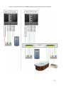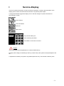
1
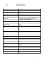
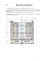
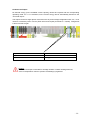
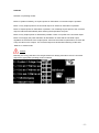
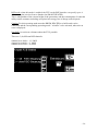
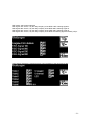
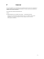
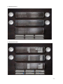
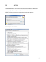
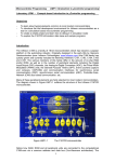
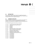
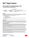
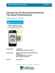
Manual
Release: 04.10.2015
SMART-HEATER V2.0
A
Table of contents
A
B
C
D
E
F
G
Table of contents............................................................................................................ 2
Functions ......................................................................................................................... 4
Safety ............................................................................................................................... 5
Case ................................................................................................................................. 6
Specification ................................................................................................................... 7
Mechanical Installation................................................................................................. 8
Electrical Installation .................................................................................................... 9
G1 Main-Connection .......................................................................................................... 13
G2 Universal-Output.......................................................................................................... 14
G3 Transducer functions ................................................................................................... 15
G4 Transducers, position in the grid ................................................................................ 16
G5 Transducers, position "consumption" ....................................................................... 17
G6 Transducers, position "generation" .......................................................................... 18
G7 Transducer, connection ............................................................................................... 19
G8 DRUM-HEATER ......................................................................................................... 21
G9 Cratridge-heater ........................................................................................................... 22
G10 Temperature-Sensor .................................................................................................. 23
G11 Webserver ................................................................................................................... 24
G12 Modus with 2 DRUM-HEATER (Winter/Summer) ............................................... 25
G13 Ripple control receiver (RSE) .................................................................................. 27
H
Startup .......................................................................................................................... 29
I
Service-Display ............................................................................................................ 31
I1 Info-Dialog ...................................................................................................................... 32
I2 Home-Dialog ................................................................................................................... 32
I3 Menu-Dialog ................................................................................................................... 32
I4 Modus.............................................................................................................................. 33
I5 Monitoring ...................................................................................................................... 35
I6 Setpoint ........................................................................................................................... 39
I7 Errors .............................................................................................................................. 40
I8 Access for Installer ........................................................................................................ 43
J
Operation Smart-Meter .............................................................................................. 55
K
Matrix-Calculation ...................................................................................................... 59
K1 Matrix-Algorithmus ..................................................................................................... 59
K2 DRUM-HEATER-Modus (Matrix-Value of Steps 0 to 13500) ................................ 60
K3 Cartridge-Heater-Modus (Matrix-Value 0 to 3) ....................................................... 61
L
LED-Display ................................................................................................................. 62
L1 Blink frequency: Modus with DRUM-HEATER ...................................................... 63
L2 Blink-frequency: Modus with Cartridge-Heater ....................................................... 64
L3 Blink-Frequency: Modus Universal-Output .............................................................. 64
L4 Blink-Frequency: Collective fault ............................................................................... 64
M
Fuses / protective .......................................................................................................... 65
N
DynDNS for Webserver (Option) ............................................................................... 66
O
Webserver (Option)..................................................................................................... 68
P
Internet .......................................................................................................................... 77
Q
JAVA ............................................................................................................................. 80
R
Smart-Phone-Access to SH .......................................................................................... 81
S
Safety informations ...................................................................................................... 82
-2-
T
U
V
W
X
Y
Z
CE-Marking ................................................................................................................. 83
WEEE/RoHS................................................................................................................ 84
Warranty ...................................................................................................................... 85
Parameter log .............................................................................................................. 86
Legend ........................................................................................................................... 87
Manufacturer/Copyright ............................................................................................. 88
Declaration of Conformity ........................................................................................... 89
-3-
B
Functions
.
The SMART HEATER consists of an intelligent control system, which could allow an unprecedented
increase in the equity share in itself generated energy in photovoltaic, wind, or water power in
connection with a 15kW heating-power-unit.
A small revolution for the energy-conscious and aspiring to the self-sufficiency operators of a
photovoltaic system or other renewable generation systems. The SH can massively support your
heating system and might even replace, as well as the universal output a power storage, control
units, air-conditioning units, chargers, or infrared heaters, etc. specially designed for homes,
businesses and agriculture.
The system is built exclusively with wear-free and absolutely maintenance-free high-performance
components in the manufacturing industry and designed for a long service life.
Through the sophisticated control concept and the integration of various interfaces for nonproprietary consumer, also retrofit a SH is at any time possible and installed in a short time.
The mounting of the SH is easily performed by any qualified electrician.
The entire system by means of optional Webserver can be monitored via the Internet and on request
in addition to the use of remote maintenance and service support by Krentzel GmbH.
The handmade system is built in Germany, tested and distributed only through select distributors.
KRENTZEL GmbH
-4-
C
Safety
WARNING! These warnings apply to all persons who work on the SMART-HEATER
The non-observance of the following instructions may cause severe injury or installation and
maintenance of SMART HEATER result in fatal accidents may be carried out only by qualified
personnel.
Working on the SMART HEATER or its input and output-cables never if the SMART HEATER to
the mains is connected.
Before carrying out any work inside the SMART HEATER housing, make sure that no dangerous
voltages. (Main switch, etc.)
Unlock unintentionally secure voltage determine if voltage is present at the SMART HEATER or
external control circuits, perform any work on the control cables.
Externally-powered control circuits can lead to dangerous voltages even in the SMART HEATER if
the voltage supply of the SMART heater is switched off.
Live parts inside the housing are protected against direct contact if all protective covers from art.
-5-
D
Case
Front
System-Area
Display Generator
Smartmeter
Display
Consumption
Smartmeter
Display Surplus
Smartmeter
Display Service
Surplus LED
Connection-Area
Bottom
Main-Switch
on/off
Power inline
Output
Universal
CT for
Generator
Consumption
Output
Drum-Heater
Temperature
Sensors
Local-AreaNetwork
Webserver
Note: The screw connection of the system part is protected by special lacquer. The guarantee and
warranty will be void if damage.
-6-
E
Specification
Weigts
40 kg
Fuses from cabinet/grid
3x25A, 3x240V AC 50Hz
Power Connection
3Ph+N+PE
Measured value acquisition
3x100A, (separate inquiries in case of higher currents )
Heating Power with DH27
with DRUM-HEATER™ DH27 up to max. 13,5kW
Heating Power with Cartridge
with n pcs Cartridge Heater (total) max. 3x5,0kW=15kW
Matrix-control
a.) infinitely variable with DRUM-HEATER™ DH27
b.) up to max. 3 step with cartridge
Power consumption increase
up to 100%
ambient temperature
-10 to +50°C
Number of modes
6+1+2
Error messages / monitoring functions
27
Number Display temperature
6 + Setpoint
Overload protection
yes, adjustable (per phase)
Automatic phase control
yes
Wire break detection
yes, adjustable
Full supply possible (heating substitutes)
yes
Universal-Output
yes, up to 5kW
circulation pump output
yes, adjustable
Interface for ripple control receiver
yes
Display
Touch-Display in Monochrom
Optionen
Web server, additional transducers, additional temperature
sensors
Protection class
IP30
Internet visualization
yes
accessories
2 transducer, 1 User Manual (English, German)
Warranty
24 Month
-7-
F
Mechanical Installation
The SMART HEATER is to mount the enclosed fastening material on wall/carrier.
The appliance is designed exclusively for the fixed installation and not for mobile use and designed.
Watch out for a dry and solid mounting place that has cooled. (see specification: Weight, ambient
temperature, etc.)
2 piece fastenings for wall mounting are located on the upper edge of the housing.
An additional fastening hole for dowels etc. is located in the bottom behind the cover of the cable
connection compartment Center.
-8-
G
Electrical Installation
Electrical Connection
The main supply of SMART-HEATER is for 3Ph + N + PE designed depending on the external and
internal wiring voltage at different terminals into the cable connection compartment of the SH can be
connected.
The SMART-HEATER and the adjacent units must be earthed anyway for reasons of personal safety,
as well as to the reduction of electromagnetic interference and radiation. (PE)
The sensor cables (temperature) shall not be installed in combination with high-current cables, to
avoid any inductive influence on the measured values.
The cables of the SMART HEATER must be on a multiple device installation of several SMARTHEATER separately and not in series.
On the heating or universal output of SMART HEATER no EMC filters are necessary.
Beware of lines for the transmitter, if necessary shielded and sufficiently low impedance (high
diameter) if the length > 10 m is for the connection of 1 + n is heating cartridges a suitable.
-9-
Caution:
A short circuit to the terminal of the DRUM HEATER, the heating element or the
Universal-output leads to the immediate damage of the semiconductor power amplifiers in
the device. This warranty and the warranty claims shall expire.
Caution:
The SH-V requires a 3 phase power with a phase shift of 120 degrees and a right spin.
Caution:
If you should provide heaters instead of a DH, you must notify your utility may also, if the
power per phase is greater 4,6 kW. The utility checks and granted the approval or release
for the connection if necessary. Should your EVU refuse this release, do not operate the
cartridge.
Caution:
Please pay attention when choosing the MW lines that that length > 10m a larger cross
section (> 1mm) and if necessary to provide a shield for these leads. (Unilaterally set up).
The wiring for S1/S2 must be when reading influences separately and not in combination
with other power cables.
Caution:
Please make sure that on the lines of the SH no overvoltage occur through direct
or indirect by lightning.
Caution:
If DRUM HEATER operation, no series connection is not allowed with multiple DH´s
in the Hydraulic flow, to prevent overheating of the DH.
- 10 -
Caution:
The SH-V required a 3 phase grid with a phase shift of 120 degrees.
This right spin must prevail absolutely at the measuring points of instrument transformers
"Consumption" and "Production". Also the phase order shall not deviate from L1/L2/L3.
Caution:
To reduce errors, as well as inductive or capacitive influences of the cables for the
transducer, use shielded cables. The shield is then generally only one side to connect an
equipotential bonding.
Caution:
The electrician must ensure that the hedging in the meter cupboard on the correct
selectivity of LS - / SLS - F switch.
Caution:
Systems for the generation of heat based resistive consumers can slightly increase the
leakage current N or PE. Should this be the case, so the power supply of the SH
connected with a secure separate RCD with corresponding leakage current in the main
distribution.
Caution:
Some utility of the SH limit the allowed power of heat generation systems per phase
or for all phases in the TAB.
Please seek approval by your utility company before connecting the SH.
Caution:
The calculation of power-income from the difference between "Production" and
"Consumption" is limited in the control display on the maximum value of 9.999.999 Watts
(9 999kW).
.
Caution:
The measurement is carried out by transducer with max 100A per phase.
Higher currents (services) should be recorded, an appropriate transducer must be
inserted. (Separate request of KRENTZEL GmbH)
- 11 -
Caution:
It should be connected only a DRUM HEATER or a heating cartridges at the same time.
A parallel operation of these two different heating systems is not allowed.
Caution:
In the operating mode "Heating cartridge" a separate temperature-sensor must be
connected to Terminal 1 + 2 of the DRUM HEATER sensor terminals,
to the internal temp regulator of the SH the actual value of the heating water
to be communicated.
Caution:
The update time of the SDM ´ can amount to up to 10 seconds.
Therefore the displayed measured values and the resulting surplus values is never
up-to-date and can thus guarantee no 100% excess utilization by the SH.
Caution:
The ads in the touch screen and the Webserver are provided by the SDM.
Because these values are sent with up to 10 seconds of delay in the display units, the
data may significantly differ from the real values.
Caution:
There shall be no further active heating system in the hydraulic line of DRUM – HEATER
raise the temperature of water in addition, because the thermal protection switch is
internally installed in the DH can trigger. (> 95C)
- 12 -
Cable / line connection
All electrical connections are made without tools via the State of the art push-in technology at the
terminals in the cable compartment. As a result you can use, solid wires also stranded with and
without wire end ferrules. You need no special tools: using the integrated operation handle loosen
wires easily and quickly. Simply press the Orange control button and the contact is opened.
G1 Main-Connection
Install from the main distribution/counter Cabinet for the SMART HEATER at least a 5x4mm cable
with a maximum length of < 10 m. For longer lengths of cable, you increase the cross section
according to the VDE guideline.
Make sure that the connection point via a residual current circuit breaker and circuit breaker (3x
25A) in the meter cupboard is secured.
In the SH is connected directly to the terminals L1, L2 and L3 and N (blue) Terminal and Terminal
PE (green). Assignment is done from left to right!
Main-Line L1
Wire brown
Main-Line L2
Wire black
Main-Line L3
Wire grey
Main-Line N
Wire blue
Main-Line PE
Wire green/yellow
- 13 -
G2 Universal-Output
No thermal energy (in the available excess capacity) should be required and the corresponding
operating mode "uni = a" is activated, so the excess energy will be automatically directed to the
"universal output".
This output can be for single-phase consumers such as power storage refrigeration units, etc., to be
used for a maximum power of 5 kW. (EVU inform and request performance > 4,6kW) Assignment
is done from left to right!
Output Universal 240V max 5kW
Wire brown, L1
Output Universal 240V max 5kW
Wire blue, N
Output Universal 240V max 5kW
Wire gr/ge, PE
Caution:
The universal output is intended for cartridge-heaters or similar heating elements,
since no temperature control to prevent overheating by regulators.
- 14 -
G3 Transducer functions
For proper operation, install transducer 2 PCs. To run only the 3 phases of the respective connection
point through the rectangular openings of the transducer.
Caution:
No direct connection to the public mains network is necessary, only the transducer contacts behind
the cover are to prove! The contacts behind the cover are an if necessary shielded Control-Wire or
with an increase of Wire-diameter to lead the SMART HEATER. (if Wireslenghts > 10m) The
transducer trio of the "3 in 1 series" with 100A/5A can be mounted directly before or after a circuit
breaker. Mounted only on the top-hat rail with DIN carrier rail holder.
1. Transducer for consumption : Put the transducer in the meter cupboard to a free place on a tophat rail. This must be the current consumption of the House without compromising the
performance of the SMART-HEATER and measure without the power generated.
2. transducers for generating : Set the transducer after the inverter in your production system, the
AC output or also in the meter cupboard .
Caution:
The SH-V 3 required phase grid with a phase shift of 120 degrees. This right
spin must
prevail absolutely at the measuring points of instrument transformers "Consumption" and
"Production". Also the phase order shall not deviate from L1/L2/L3.
Caution:
Each performance at the measuring points is calculated by the SH totaly all
3 phases. If you have only a phase at the measuring points "Generation"
or "Consumption" available, the openings for L2 and L3 on the MW will remain free.
Caution:
The performance calculation in the measurement locations of the SH is carried
out by the formula: P = U x I x Cosphi. (Power calculation).
Test your production system (such as Inverter), that of the CosPhi prescribed
by the VDE and EVU as the value CosPhi = 1. reached 0.9.
- 15 -
G4 Transducers, position in the grid
transducers
"Generation"
transducers
"Consumption"
protection
supply for SH
main fuse
to power-plant
residual
Circuit breakers
(FI)
- 16 -
G5 Transducers, position "Consumption"
- 17 -
G6 Transducers, position "Generation"
- 18 -
G7 Transducer, connection
The 3 phases of the electrical wire through the openings and in any case comply with the order.
Through the right opening of the transducer L1 through the left, L2 through the middle and L3
through the left.
The flow of the power is always from P1-> P2.
Should negative performances in the display are shown in the smart meters, the flow direction was
confused. (you must change it)
- 19 -
The reading wire according to the wiring diagram to connect is on the 6 measurement terminals
behind the cover. The designation of S1 or S2 refers to the Terminal designation on the transducer.
Assignment is done from left to right!
SDM Generation Phase L1
Connector down -> S2, Connector top -> S1
SDM Generation Phase L2
Connector down -> S2, Connector top -> S1
SDM Generation Phase L3
Connector down -> S2, Connector top -> S1
SDM Consumption Phase L1
Connector down -> S2, Connector top -> S1
SDM Consumption Phase L2
Connector down -> S2, Connector top -> S1
SDM Consumption Phase L3
Connector down -> S2, Connector top -> S1
- 20 -
G8 DRUM-HEATER
A DRUM HEATERs must be connected with a 16 x 2, 5mm + PE Wire. This is only on the
numbered order of assignment. The internal ceramic elements of the DH and Thermo- monitoring
are integrated in the DH and require no further connection.
The operating parameters of the DH are stored as a set of parameters in the SH-V by default. If you
want to use a third-party product, check the specification and operating parameters of the
manufacturer and apply the change in the "control" menu of the
Caution:
No function guarantees or warranty claims can be applied incorrectly entered operating parameters
of the DH.
Assignment is done from left to right!
DRUM-HEATER DH-27
Wire 01
DRUM-HEATER DH-27
Wire 02
DRUM-HEATER DH-27
Wire 03
DRUM-HEATER DH-27
Wire 04
DRUM-HEATER DH-27
Wire 05
DRUM-HEATER DH-27
Wire 06
DRUM-HEATER DH-27
Wire 07
DRUM-HEATER DH-27
Wire 08
DRUM-HEATER DH-27
Wire 09
DRUM-HEATER DH-27
Wire 10
DRUM-HEATER DH-27
Wire 11
DRUM-HEATER DH-27
Wire 12
DRUM-HEATER DH-27
Wire 13
DRUM-HEATER DH-27
Wire 14
DRUM-HEATER DH-27
Wire 15
DRUM-HEATER DH-27
Wire 16
DRUM-HEATER DH-27
Wire PE
- 21 -
G9 Cartridge-heater
For the operation to heating instead of a DH, you must take 3 heating rods of the cartridge to the n
connector 07/08 + 09/10 + 11/12 + to connect PE.
Pay attention to the maximum power of 5 kW per heating element. (3x5kW total) Should you want to
connect more than 1 heating element, the connection of n cartridges in an external junction box is
making.
Caution:
The amount of the individual values of the heating elements (H1, H2, H3) the cartridges must meet
the following conditions: All heating elements must have the same power. 3 x 3kW, example: 3x1kW,
3x5kW, etc.
No Star-Connection is not allowed for the heating elements of the heating cartridge / or have the
triangle connection. Should the case be to change internal wiring of the cartridges on single wiring,
so that each element is individually accessible (phase/N).
Assignment is done from left to right!
DRUM-HEATER DH-27
Wire 01
DRUM-HEATER DH-27
Wire 02
DRUM-HEATER DH-27
Wire 03
DRUM-HEATER DH-27
Wire 04
DRUM-HEATER DH-27
Wire 05
DRUM-HEATER DH-27
Wire 06
DRUM-HEATER DH-27
Wire 07/ L1 / Cartridge-Heater
DRUM-HEATER DH-27
Wire 08/ N / Cartridge-Heater
DRUM-HEATER DH-27
Wire 09/ L2 / Cartridge-Heater
DRUM-HEATER DH-27
Wire 10/ N / Cartridge-Heater
DRUM-HEATER DH-27
Wire 11/ L3 / Cartridge-Heater
DRUM-HEATER DH-27
Wire 12/ N / Cartridge-Heater
DRUM-HEATER DH-27
Wire 13
DRUM-HEATER DH-27
Wire 14
DRUM-HEATER DH-27
Wire 15
DRUM-HEATER DH-27
Wire 16
DRUM-HEATER DH-27
Wire PE/ PE/ Cartridge-Heater
- 22 -
G10 Temperature-Sensor
Only the core temperature sensor will be connected via the sensor pairs (4 wires) from the DH to the
SH is necessary for the operation of the SH. Make sure that even when the cartridge-Heater operation
of the SH core-sensor clearly can detect the temperature of the water reservoir. To connect 1/2 the
temperature sensor (as accessory available) to the connector. The remaining sensors for T1 / T2 /
T3 and if any buffers are generally optional. Because it is pure resistance measurement by means
of PT1000 sensors, a reverse polarity of the connecting wires is not relevant. Make sure that the
sensor wires separately and not be laid in a harness or a cable channel with electrified wires. A
measured value of distortion due to the induction of the electrified wires otherwise or the display of
measured values shuttling remarkably strong.
Assignment is done from left to right!
Sensor T2
Wire a/b
Sensor Water-Buffer/Storage
Wire a/b
Sensor T1
Wire a/b
Sensor T3
Wire a/b
Sensor Wire vom DH
Wire 1/2
Sensor Wire vom DH
Wire 3/4
- 23 -
G11 Webserver
For the visualization of the SH in the Internet, a Web server can be installed optionally. SH is already
preset for the operation of a Web server and requires only the connections to the SH to your
router/switch. Pay attention to the configuration of your router (see Wire in chapter N) connector
"front on the Web server knows" connector plug fit LAN cable (rs45) up to the Web server "green"
top of the Web server plug
Connector
green
Connector
white
- 24 -
G12 Modus with 2 DRUM-HEATER (Winter/Summer)
The SMART HEATER can be used also for the operation of 2 DRUM HEATER (cartridge-Heater).
You can use a DRUM HEATER (cartridge heater) pool heating and in the winter as an example in
the summer a DRUM HEATER (cartridge heater) for heating. The switching is done manually on the
shift-box. (Supplied by your electrician)
Caution:
For the operation of the SH to a switch box, the red link (17-head) and the Green sensor wire (2wire) are necessary to connect the green dotted lines are optional temperature sensors, which are
not necessary for the operation.
They are not needed, just uncheck the open-circuit monitoring of these sensors (control menu). For
the operation of DH on a swimming pool, you must integrate a heat exchanger, if the pool water is
chlorinated.
- 25 -
System configuration with 2 piece DRUM HEATER (example: Winter/Summer operation)
- 26 -
G13 Ripple control receiver (RSE)
The concept of "network stabilization through controlled decentralized power take-off" is
based on the intelligent control of SMART HEATER (3) and the high-performance heating
element 13, 5kW DRUM HEATER (2) which can be remotely controlled through a ripple
control receiver RSE (4) of the electricity supply company (6). About this RSE interface
integrated in the SMART HEATER (3) EVU (6) from a distance (all Germany) via RSE
signal (7) can enable the SMART HEATER (3) electrical heating by means of DRUM
HEATER (2). The energy required is obtained directly from the SMART HEATER (3) from
the net (5) and leads directly to the network relief at. There are 3 different power levels,
which can be activated via the circular control signal (7) of the electricity supply company (6)
from a distance and if necessary:
channel level 100% = 13, 50kW (round 13, 50kW)
channel level 060% = 8, 10kW (rounded 08, 00kW)
channel level 030% = 4, 05kW (rounded 04, 00kW)
Assignment is done from left to right!
COM
+ 24V
Receiver-Signal100%
Potential-Free Contact K4 from RSE and COM
Receiver-Signal060%
Potential-Free Contact K3 from RSE and COM
Receiver-Signal030%
Potential-Free Contact K2 from RSE and COM
Receiver-Signal000%
Potential-Free Contact K1 from RSE and COM
DATA 5
n. n.
- 27 -
Residence „a“
4.) RSE
(Receiver)
Residence „b“
Residence „n“
1.) Buffer
storage
(Water)
1.) Buffer
storage
(Water)
1.) Buffer
storage
(Water)
2.) DRUMHEATER
2.) DRUMHEATER
2.) DRUMHEATER
3.) SMARTHEATER
4.) RSE
(Receiver)
3.) SMARTHEATER
3.) SMARTHEATER
4.) RSE
(Receiver)
7.) RSE-Signal
5.) Grid
6.) EVU
(Power-Plant)
- 28 -
H
Startup
After the proper installation & connection: The main line (5 x 4, 0 mm) and 3x25A hedging in the
meter cupboard/distribution of the heater-wire (at DRUM HEATER 16 x 2, 5 mm + PE or 6 x 2, 5 mm
+ PE for Cartridge-heater/n) the sensor-wire of the DH (4 x 0, 75 mm) if necessary the circulation
pump on the DH if the temperature sensors (PT1000, 2-wire) (in buffer mode also the buffer sensor)
of the transducer for the Self-Consumption (6 x 0, 8 mm) of the transducer for the self-produced
energy (6 x 0 , 8 mm) the SMART HEATER by means of the integrated main switch can be switched
on.
As a startup screen appears the firmware ID and changes automatically after about 5 seconds to
"Home image", which can be changed in all other menus. Again, the image can be called any time
from the home menu-> info.
Caution:
If an error is made, the display color from white - changes > red and all functions and power
amplifiers/outputs are disabled. (the display is blocked for 5 seconds) Only the display-color changes
according to the fault again on white and the proper function of the SMART HEATER is guaranteed.
- 29 -
Caution:
First, the installer must check all parameters/settings in the control menu, correct, and re-record if
necessary.
Proper function is necessarily dependent on the correct entries in the menu 'Control'. Access to the
control menu is protected by password. (See control).
Under normal circumstances, are there to make any changes and already set for DH operation.
Should the SH be used with cartridge-Heater, is to enter just the cartridge-Heater performance and
change the type of heating on "Cartridge-Heater".
- 30 -
I
Service-Display
The SH is operated exclusively via the touchscreen 'Operation'. Inactivity, the illumination of the
display goes out after 10 minutes and is switched on by pressing button again.
A recognized disorder toggles the display color to red and changes only after resolved error
automatically on white.
menu forward
menu backwards
Quit error
Menu home
Entry field for data input .
After confirming with Enter .
Press ESC to cancel the command .
Caution:
The control panel stores all parameters in a built-in RAM memory.
During a power outage, the buffering is done by a button cell (in the system control panels/part of the
SH.
A replacement of battery can perform by qualified personnel only. The shelf life is about 5 years.
- 31 -
I1 Info-Dialog
Display the firmware version and serial number appears automatically after switching on the power
supply. The image changes automatically after approx. 5 seconds to the home screen. The desired
language can be selected in this dialog.
I2 Home-Dialog
Selection to the Info screen or next
I3 Menu-Dialog
Selection to the home screen or more submenus
- 32 -
I4 Modus
Selection of operating modes:
Mode 0: System is standby, no surplus-power for Generation or universal output is possible.
Mode 1: Only surplus-power to the universal output. No Power for Generation is possible.
Mode 2: Surplus-power for Generation is possible. The remaining surplus power to the universal
output is redirected automatically after reaching the temperature set point.
Mode 3: Only surplus power for Generation possible. There is no power to the universal output.
Mode 4: Full supply the power allocation for Generation is made and the universal output
regardless of the amount of the surplus power. It derives the maximum performance to reach the
Temp set value on the outputs. The universal output is activated after switching off the heat.
Mode 5: in manual mode.
Caution:
Basically, the energy allocation for heat generation has always precedence over the universal
output if the appropriate operating mode is selected.
- 33 -
RSE mode: when this mode is enabled, the EVU on the RSE interface can specify up to 4
different surplus services from a distance the SMART HEATER.
This is independent of the current height of the generation, and the consumptions. So that the
utility can the customer including at requires heat energy free of charge at the disposal.
Caution: For this operating mode must the DRUM HEATER to a buffer tank can be
connected and the corresponding operating mode " to buffer" to be activated, otherwise an
error is displayed.
Non-RSE: no action at a distance about the EVU possible.
There are 3 (4) different RSE channels:
channel level 100% = 13, 50kW
channel level 060% = 8, 10kW
channel level 030% = 4, 05kW
- 34 -
I5 Monitoring
Request heat: Active, when the core temperature below the entered value.
Full message heat: active when the core temperature is below the setpoint value minus the hysteresis
decrease.
DRUM HEATER operation: Active when DH mode is selected
Cartridge-Heater mode: active when the operating mode for cartridge Heater is selected
Mode DH to buffer: active, in conjunction with cache mode
DH for return rise: active, for return rise
Surplus available: active, if more power generated, as consumption is emergency-main-line
Power from grid: active when in operating mode "full care" performance must be obtained from the
EVU, because there is not enough surplus power.
- 35 -
RSE mode: Active when selected
RSE signal 100: Active, if by the utility company of the RSE 100% switching signal is .
RSE-signal 060: Active, if by the utility company of the RSE 060% switching signal is.
RSE-signal 030: Active, if by the utility company of the RSE 030% switching signal is.
RSE-signal 000: Active, if by the utility company of the RSE the switching signal for 000% (off) is.
Active stage: displays the respective active power amplifier of the performance part.
- 36 -
Temperature: displays the respective temperatures in Celsius.
Caution:
Sensors not connected or defective sensor cables lead that shows the value of 819.
Generation: Display the generated renewable power. (limited to 32.000W)
Consumption: Indicator of the consumption power. (limited to 32.000W)
Grid income: Display of differential performance of generation and consumption. (limited to 32.000W)
Current heat output: display of the measured current performance to generate heat.
Associated heat output: display the provided heat output.
Current universal service: display of the measured current power of the universal output.
Universal service assigned to: display the provided power for the universal output.
The display value of the current thermal power can be significantly lower than was allocated by the
SH. (assigned heat output) This is line-loss and the manufacturing tolerances of the respective
heating system caused by.
When the DRUM HEATER operation, the power difference may be higher, due to tolerances in the
ceramic components and be called normal.
- 37 -
RSE power date: display the power decrease by a ripple control receiver command requested by
the utility company. (100% or 60% or 30%)
RSE power cycle: display the power required by your electricity company within a measuring cycle.
(between the switch and switch-off command of the RSE)
RSE total power: display of power requested so far by the utility company. (netted - added)
Service interval timer: If > 100 service inform (via factory reset = 0)
- 38 -
I6 Setpoint
Temperature setpoint: input of the set point temperature, which should reach the DH or the heatingcartridge in the heating system. The maximum input value is limited by the limit in the control menu to
the top.
Delta temperature DH/buffer: input of the set point temperature, from which temperature difference
from the DH to the buffer tank, the circulation pump is switched on. This value is required only for the
DH mode with a buffer tank.
- 39 -
I7 Errors
Wire break: the cable of the temperature sensors are monitored for wire breakage or short circuit.
(the sensor values are then displayed: 819) The sensors for T1, T2 and T3 are connected for the
operation of the SH not necessarily necessary and only when necessary.
The monitoring of these sensors is accordingly in the menu 'Control' .
The sensor 'Buffer' is necessarily required for "DH buffer" mode and must be connected and its
monitoring in the menu 'Control' to be activated.
Troubleshooting possible Installer: check of the sensor cables and connection in the wiring
area of the SH. If necessary replacement of the sensor, or lines.
Core/heater temperature: If the maximum temperature of the heating system, entered under
'Control' is achieved, the SH recognizes this as a fault.
Troubleshooting possible Installer: control of the core-sensor.
Limit temperature system: the system area of the SH regulates and controls the surplus power to
15kW via high-power electronics. The semiconductor is monitored for temperature and report this at
the maximum permitted value is reached. (under control)
Distributor contact: no fault remedy possible. Device replacement necessary
Missing phase L1/L2/L3: all 3 phases are necessary for the proper operation of the SH. If one of the
phases is missing in the local area network or network congestion reduces one of the voltages
below 200V AC, this is detected and displayed as a disorder. (normal 230-240V AC)
Troubleshooting possible Installer: power discharge by switching off by strong consumer in
the House and checking the mains voltage of the EVU on the smart meter of the SH and
their backups in the connection compartment.
- 40 -
Incorrect input cartridge Heating-Power: menu 'Control' to enter the 3 heat outputs are
for cartridge Heater operation. All 3 of the Cartridge heater heating
elements must have the same power. (sample. 3x3kW etc.)
Troubleshooting possible Installer: correct the input
Parameter universal power too small: In the menu 'Control' the required power consumption of the
device (battery charger for power storage, refrigeration, etc.) is for the Universal-Output to enter.
When in operating mode 1, 2 or 4, the power measured by the SH exceeds this value, this will be
shown as a disorder.
Troubleshooting possible Installer: correct the input
Power cartridge Heater greater than specified: In the menu 'Control' the services of 3 heating
elements of the Cartridge Heater are to enter. If the heating mode "with cartridge-Heater" is
selected and the power measured by the SH exceeds this value, this will be shown as a disorder.
Troubleshooting possible Installer: correct the input
Temp set value > limit: the maximum temperature set point is defined in the menu 'Control'. When
the operator exceeds this value at the input (menu setpoint), this is displayed as error.
Troubleshooting possible Installer: correct the input
Fatal system error: the parameter sets stored in the SH and algorithms for matrix control are
continuously monitored by the built-in firmware of the PLC. Should be detected when the parity
check or data block an error, this will be shown as a disorder.
SH-ISO error: Detected fault of the housing insulation of the SH
Distributor contact: no fault remedy possible. Device replacement necessary
- 41 -
Bus error SMD x: The smart meter is placed at the front of the SH and communicate with the
control system of the SH via a bus system, which is constantly monitored. Should the
corresponding smart meters send any feedback, this will be shown as a disorder.
Distributor contact: no fault remedy possible. Device replacement necessary
Power phase x too big: the maximum load of the phase of L1, L2 and L3 is defined in the menu
'Control'. In case of an overload, this is indicated as a disorder.
.
Troubleshooting possible Installer: correct the entry and check the power of the
Consumption (Universal)
DRUM HEATER Overtemperature: Thermo-Switch in the DH has raised .
Distributor contact: no fault remedy possible. Device replacement necessary
AA. Defective Assembly: SH defective control Assembly.
Distributor contact: no fault remedy possible. Device replacement necessary
DH-buffer operation without buffer sensor: buffer temperature sensor is
missing, defective or its wire-breakage monitoring is not enabled.
Troubleshooting possible Installer: fix the sensor line, the input for the
open- circuit Monitoring.
- 42 -
I8 Access for Installer
Access to the control menu is password-protected, because these settings may be changed only by
trained specialist personnel.
Code: __________ (only for the installer/qualified personnel)
By entering incorrect parameter, the system can not be destroyed, but produce at least in
his position precarious statuses. Any warranty claims against the manufacturer do not
have a subsequent alteration of these parameters, if they have caused the damage and
are not a normal operation. The sharing in the control menu turns off automatically after
approx. 5 minutes after inactivity
Perform code and enter again control select and confirm.
The submenus are released with real input.
.
- 43 -
I9 Control
Controll X: all wires of temperatures-sensors monitors for a breakage or a short circuit .
The sensors T1, T2 and T3 are for the operation of the SH not imperative (exception sensor for
buffer) and connect it only when needed. The monitoring of these sensors can here according to /
or be voted out. The sensors monitors for core and system are always active and can not
deactivated.
Preset at the factory or by reset: on
.
- 44 -
Max TEMP system: limit for system-temperature of power electronics .
Preset at the factory or by reset: 55 C.
Hysteresis control: the setpoint of temperature minus the hysteresis makes the switch-on point for
the requested heating power of the SH.
Preset at the factory or by reset: 3 C.
Switch-off time power amplifiers: the response times for the shut-down of the power electronics can
be extended manually. The switch point in the zero passage of the sine wave AC voltage will not
affect. (Input in x 10 MS).
Preset at the factory or by reset: 0 (0.0 seconds)
Power factor correction (multi): The production-related fluctuation in the power of DH's can
be up to 10% of the nominal power of DH's. The input power of the DH does not follow a
linear function but an exponential function at the bottom of 2nd degree (0-1kW).
In order to adjust the desired power of the DH's actually needed surplus power (so that as close to
the redirection performance is), the exponential function by means of a multiplier to be adjusted.
(Entered in 1 to 99).
Preset at the factory or by the reset code 50 (multiplier)
Power factor correction (Addi): The production-related fluctuation in the power of DH's can
be up to 10% of the nominal power of DH's. The input power of the DH does not follow a
linear function but an exponential function at the bottom of 2nd degree (0-1kW).
In order to adjust the desired power of the DH's actually needed surplus power (so that as close to
the redirection performance is), the calculated surplus power to be adjusted by means of an
additionally added performance value. (Entered in 0 to 99).
Preset at the factory or by a reset: 0 (addition)
- 45 -
Limit core temperature: As additional safety routine, the SH has a limit value monitoring for the core
temperature of the DH or the Cartridge Heater, which generates an error when reached.
Preset at the factory or by reset: 95 C.
- 46 -
Service interval timer: intrinsic counter for service intervals. If the value is > 100 please inform
customer service.
Preset at the factory or by reset: 0 (display only)
Modbus delay: delay value for error evaluation of bus-components (input in x 10msec)
Preset at the factory or by reset: 500 (5 seconds)
Heating type: select of the operating mode with DRUM HEATER or cartridge heater. The selection
is carried out by entering the appropriate code in the input field .
Preset at the factory or by reset: 1
- 47 -
Cartridge heater power 1,2,3: input of 3 heating element benefits in cartridge-Heater operation.
Enter at n cartridge Heater, the power according to the examples as sum-power. The individual
values of the heating elements (H1, H2, H3) the cartridge Heater must be identical.
Is done by entering the corresponding power in W in the input field.
Preset at the factory or by reset: 0
- 48 -
Display configuration: Changes the contrast or the brightness of the display can be carried out here.
In addition, also a display test, as well as specific changes of the touch function and other functions
is integrated in the sub menu "Setup".
Settings/changes in the setup of the displays can lead to malfunction of the
SH.
- 49 -
Uni-output power: Input of the nominal power of the universal Consumption
Preset at the factory or by reset: 500 (watt)
Delay uni-monitoring: The power consumption of the universal Consumption is monitored by the
SH. Because some devices have a high starting current by switch on, the monitoring may be
delayed to get no interference. (Input in x 100msec)
Preset at the factory or by reset: 333 (33 seconds)
Limit power L1/L2/L3: the power consumption of all 3 phases are monitored by SH. The design of
power amplifiers - size is set kW per phase in continuous operation and protected by this limit
overheating for max 5.
Preset at the factory or by reset: 5500 (watt)
Manual: For troubleshooting or start-up of the SH in conjunction with special Consumption as the
heat generator or universal Consumption the installer can control the individual amplifiers manual .
Caution:
In manual mode, the outputs without considering errors or temperature / set values / limits are
used. The system can be driven in this mode limitless, even up to the point of self-destruction.
(Time-delayed display of the States by a / off to 3 seconds)
Preset at the factory or by reset: from
- 50 -
DH-Betrieb an Buffer: If you want to operate the DH to a buffer tank (water tank), you enable this
mode "1". In the port, you must also connect the temperature sensor "Buffer" and enable.
The circulation pump starts, if the core temperature of the DH + Delta > buffer temperature is and
switches off after the set delay time.
The DH as return rise (without heat on a buffer) should be provided, then the mode "2" is to choose.
The temperature sensor 'Buffer' can be eliminated then. The circulation pump starts at the same
time with a heat level and switches off after the set delay time.
Preset at the factory or by reset: 1
- 51 -
Overrun time in sec: input of the after-run time of the circulation pump to a switch-off command.
(Input in x 10msec)
Preset at the factory or by reset: 500 (5 seconds)
Pump kick period: input, when the next pump kick should turn on the circulation pump for the
duration of a pump kick to avoid a blocking of the pump after a period of inactivity. (Entered in STD)
Preset at the factory or by reset: 48 (48 hours)
Pump kick duration: input, how long should the last-time the duration of pump kick.
(Input in x 10msec)
Preset at the factory or by reset: 500 (5 seconds)
.
If no pump kick is required, change the parameters for the pump kick period to "00" and a
permanent operating on "99".
Reset RSE: The power decrease (cycle power) each requested by the utility company is totaled
after each request cycle and stored in the SH.
By activating the factory reset this count value is set to zero .
- 52 -
Reset factory setting: factory all relevant parameters of the SH are preset to default values for quick
setup. These values can be reset at any time if necessary using the "reset factory setting" on the
initial state.
Preset at the factory or by activating the factory settings:
Bezeichnung
Parameter
Einheit
Kommentar
Modus
0
System standby
Temperature setpoint
40
Grad Celsius
Delta Temperatur DH/buffer
3
Grad Celsius
RSE-Modus
1
Power Cartridge-Heater L1,2 und 3
0
Wire-brocken monitoring
on
all monitoring are active
Heating-Modus
1
DRUM-HEATER
DH-Modus
1
DRUM-HEATER with Buffer
only for modus Dh+Buffer
no RSE-modus
Watt
Universal-Power
500
Watt
normal power for Uni etc.
Universal-Output, delay control.
333
X 100 msec
delay-time for control ( 33 Sek)
Limit Temp. system
55
Grad Celsius
Hysterese Temperatur-control
3
Grad Celsius
Delta Temperatur DH/Puffer
Delay-time output-signal
0
X 10 msec
( 0,0 Seconds)
Power factor correction (multi)
50
Power factor correction (Addi)
0
Watt
Limit for Temperatur Kern/Cartridge-Heater
95
Grad Celsius
Delay-time Modus
500
X 10 msec
( 5 Sec)
Follow-up time circulation pump
500
X 10 msec
( 5 Sec)
Pumpen-Kick-Periode
48
X Std
(all 48 hours)
Pumpen-Kick-during-time
500
X 10 msec
(5 Sec)
5500
Watt
RSE Power total
0
kWh
Service-Intervall counter
0
pcs
Limit Power per Phase
L1, L2, L3
Change Exponential-Function
Change Quantität of DH-Power
- 53 -
Logout: Adjustments must be performed once during the commissioning in the control menu. All
entries/changes are made, the menu can be exited about this feature .
The control menu after inactivity changes automatically after 5 minutes in normal mode to
the start-screen:
- 54 -
J
Operation Smart-Meter
In the SMART HEATER, 3 PCs smart meters are integrated in the upper part. This high-precision
instruments are used to logging and require no separate parameter assignment through the
installer or operator. Various readings can be selected and read using the touch buttons. The
operation's associated what measuring point for the 3 SDM that it is identically, regardless In the
SMART HEATER, 3 PCs smart meters are integrated in the upper part. This high-precision
instruments are used to logging and require no separate parameter assignment through the
installer or operator. Various readings can be selected and read using the touch buttons. The
operation's associated what measuring point for the 3 SDM that it is identically, regardless.
Measured values of Generation
Measured values of Consumptions
Measured values of Surplus
Measured values of the Generation:
display the voltages, currents, and services individually or summed for the total energy produced by
wind, water or photovoltaic.
Measured values of Consumption: Display the voltages, currents, and services individually or
summed for the total consumption energy in your home or business.
Measured values of Surplus:
Display the voltages, currents and power individually or summed for the entire in the DRUMHEATER, Cartridge-Heater, or universal-output diverted energy.
- 55 -
Key for voltage and current: display the voltages and currents of the measuring point
can by touching this button .
Note:
Prior to delivery of a SH is this over several hours on maximum power in our test bench of
Krentzel GmbH tested. SH are due to the display of the SDM and the display of the Web server
already some kW added in the fields of the display. This is not an error, but a quality indicator and a
ready and tested system thus signaled the customers.
The bar indicator shows current measured power of SDM from the SH is in operation .
- 56 -
Services button: by pressing this key you can display the power of the measuring point.
Following values are available:
active power P = U * I * cos-phi
reactive power Q = U * I * sin phi
apparent power S kW = U-I:
real power (P) will be in Watt active power P = U * I * cos phi = W (1000 W = 1kW) kVar:
reactive power (Q) is in var (Volt Amperes Reactive)
specify reactive power Q = U * I * sin phi = var (1000 var 1kvar =) kVA: apparent power (S) VA
specified in apparent power S = voltage (U) * (I) VA = current (1kVA = 1000VA)
Netted values, peak, power factor, frequency, etc. button:
by pressing this button you can display the special values of the measuring point.
- 57 -
- 58 -
K
Matrix-Calculation
K1 Matrix-Algorithmus
The matrix of the SH produces the disposition of surplus-power in smallest possible deliverables in
pending status for the connected heating system according to an effective algorithm to maximize
the efficiency of the heater.
When using a DH is the maximum value of the matrix quasi almost continuously, with a cartridge
heater can reach only the value of 3.
As a general rule: the bigger the matrix value, content is greater the efficiency of the system.
Note:
At cartridge-Heater with relatively high rates of SMART-HEATER can control only the cartridge
heater, if the power of the difference is greater than 1 power specification.
Thus decreases the efficiency of the system in a cartridge-Heater high power.
The use of a DRUM-HEATER is to provide for the achievement of the highest efficiency and the finest
gradation (highest value of matrix). (DH)
Caution:
The cartridge heater you will be used must have 3 heaters. (H1, H2, H3) The individual heating
capacities of 3 heating elements must be all the same.
The heating elements does not have a Star/Delta connection .
- 59 -
K2 DRUM-HEATER-Modus (Matrix-Value of Steps 0 to 13500)
- 60 -
K3 Cartridge-Heater-Modus (Matrix-Value 0 to 3)
Alternatively, you can run the SMART-HEATER with 1 or more (different) cartridge-heater. (All
cartridge heater must have 3 heaters)
If you use one or more standard cartridge-heater/n as the heating system, pay attention to
the correct internal wiring of the cartridge heater. 3 cartridge heater are necessary, which are
individually connected to the SMART-HEATER.
The operating voltage of the heating elements is prescribed with 240V/AC. (Operation with 400V in
the star-Delta starting is not possible)
Pay attention to the potential equalization (PE). You should be more than 1 connect PCs cartridge
heater, must be no greater 3x5kW the total connected load of the heating elements. Multiple cartridge
Heater are parallel to connect and to connect the SMART HEATER as "one" cartridge heater.
Pay attention to the potential equalization (PE). The power parameters of the corresponding
cartridge-Heater power shall be deposited in the SMART HEATER manually. (Menu control) To take
a standard cartridge heater and note the 3 individual services, to enter them as total power in the
commissioning phase under control.
Do you want to connect multiple cartridge Heater, the connection 1, 2 or 3 must each do not exceed
5kW. Thus, 3 x 5 kWh maximum power, when the cartridge heater operation arise.
The sum power of the individual heating elements must be the same for all 3 heating
elements .
- 61 -
L
LED-Display
To the Visual display of the diverted amount of energy, a white high power LED is installed in the
cable-area is illuminated by the transparent logo in the cable compartment cover.
The LED flashes at the pace of the diverted amount of power of the DRUM HEATER, cartridgeHeater or universal device and will also serve as an optical fault indicator.
Caution:
The LED can be switched off by tilting the upper part of the LED bracket.
The possibility to switch off the LED is necessary, because with an open cable-area and active
operation of the SH the very bright LED (> 30.000 mcd) eyesight can hurt.
LED
- 62 -
L1 Blink frequency: Modus with DRUM-HEATER
1x Blink
2x Blink
3x Blink
4x Blink
5x Blink
6x Blink
7x Blink
8x Blink
9x Blink
10x Blink
11x Blink
12x Blink
13x Blink
14x Blink
15x Blink
16x Blink
17x Blink
18x Blink
19x Blink
20x Blink
21x Blink
22x Blink
23x Blink
24x Blink
25x Blink
26x Blink
27x Blink
Surplus Power between 00000-00500 Watt
Surplus Power between 00500-01000 Watt
Surplus Power between 01000-01500 Watt
Surplus Power between 01500-02000 Watt
Surplus Power between 02000-02500 Watt
Surplus Power between 02500-03000 Watt
Surplus Power between 03000-03500 Watt
Surplus Power between 03500-04000 Watt
Surplus Power between 04000-04500 Watt
Surplus Power between 04500-05000 Watt
Surplus Power between 05000-05500 Watt
Surplus Power between 05500-06000 Watt
Surplus Power between 06000-06500 Watt
Surplus Power between 06500-07000 Watt
Surplus Power between 07000-07500 Watt
Surplus Power between 07500-08000 Watt
Surplus Power between 08000-08500 Watt
Surplus Power between 08500-09000 Watt
Surplus Power between 09000-09500 Watt
Surplus Power between 09500-10000 Watt
Surplus Power between 10000-10500 Watt
Surplus Power between 10500-11000 Watt
Surplus Power between 11000-11500 Watt
Surplus Power between 11500-12000 Watt
Surplus Power between 12000-12500 Watt
Surplus Power between 12500-13000 Watt
Surplus Power between 13000-13500 Watt
- 63 -
L2 Blink-Frequency: Modus with Cartridge-Heater
1x Blink
2x Blink
3x Blink
Redirected power corresponding to the heater power H1
Redirected power corresponding to the heater power H1+H2
Redirected power corresponding to the heater power H1+H2+H3
L3 Blink-Frequency: Modus Universal-Output
1x Blink
Universal-Output aktiv
L4 Blink-Frequency: Collective fault
continuous Blink
collective fault
- 64 -
M
Fuses / protective
The SH-V has 7 fine fuses plus an automatic overload detection of the individual phases, in
order to protect people and the system against damage.
The backups have an automatic fuse failure detection, which is indicated by LED on the top
locking head after triggering. (LED = red - has> fuse tripped)
Distributor contact: no fault remedy possible. Device replacement necessary
Assignment is done from left to right!
1. Fuse 1A/ 240V
2. Fuse 1A/ 240V:
3. Fuse 1A/ 240V:
4. Fuse 1A/ 240V:
Power-Supply DC
SDM`s L1
SDM`s L2
SDM`s L3
- 65 -
N
DynDNS for Webserver (Option)
If you have opted for the option of the Web server, you must enter a unique address for access over
the Internet browser (Internet Explorer, Firefox, etc.) for your SH.
To enable this, you need a so-called DynDns address. This address can apply for free E.g. at the
company SELFHOST (WWW.SELFHOST.DE), and choose there own a catchy name. (for example:
www.Smartheater.Mustermann.selfhost.bz) the following guide has been created as an example with
the provider SELFHOST and the router manufacturer AVM FritzBox.
Anleitung:
1. Registrieren und einen Account für eine kostenlose DynDns erstellen.
- 66 -
2. Select the router configuration the DynDNS provider Selfhost.
3. Enter your allotted by Selfhost username
4. Enter your shared by Selfhost domain name (host name)
5. Enter your nominated by Selfhost password
6. Save the router configuration.
- 67 -
O
Webserver (Option)
After the Web server is properly installed and connected in the cable compartment of SH's, follow the
instructions to configure your router (sample AVM Fritz box).
Note:
The Web server has the default IP address: 192.168.0.130 and can not be changed.
Make sure that this does not create IP conflicts on your IT-network and can change the address of
another network station with this IP.
If necessary, you must change the IP number range of the router, so that the IP 192.168.0.130 is
reached.
instructions:
1. Establish connection of SH to the Internet via the router using the LAN cable.
2. Ensure that an Internet connection is available.
3. In the browser address bar enter: http: //fritz.box
4. Enter the password for the Fritz! Box
5. Enable the expert opinion under System-> View
- 68 -
6.)
In Internet> Online Monitor on "port forwarding" click::
Or search under home network-> network the SMART HEATER (SH) and the device "Edit":
- 69 -
- 70 -
7.) Selection: Assign the SH always the same IP (192.168.0.130)
- 71 -
8.)Alternatively, click directly on "Port sharing" in the description of the device:
- 72 -
New port shares set as follows: http
- 73 -
10.) FTP Setting: FTP
11.)
telnet Setting: telnet
- 74 -
12.) SMART-HEATER settings: plc
- 75 -
13.) DynDNS adjust if necessary:
- 76 -
P
Internet
If you have applied for your web address at a DynDNS provider and the router configuration is
complete, restart your web browser (Internet Explorer or Firefox.) And enter your address as
follows into the browser most distant:
www.mustermann.selfhost.bz/smartheater.html
Caution:
As additional address of your address must always ... /smartheater.html follow.
Change your PC should show safety messages, as and / or install the missing JAVA
applications (see Java) and change the security settings for this site of the PC
to the property: trustworthy.
- 77 -
1.) Webserver/Home
2.) Webserver/Data
- 78 -
3.) Webserver/errors
4.) Webserver/Control
- 79 -
Q
JAVA
The Web server requires a Java Runtime Environment (Runtime) for display in a Web browser.
If these messages appear when you launch your SMART Heaters, confirm the site of SH as a
trustworthy site.
Replace (if necessary) your browser to Google Chrome, Firefox Safari, Opera, etc.
Disable unsigned code verification:
- 80 -
R
Smart-Phone-Access to SH
If you want to access with your smart phone (Apple or Android operating system) on the SH, this
is the browser from Spidercontrol possible.
On normal PC have the browser via a ' Java runtime environment ', with whose help the MMI can
run as Java applets in your browser. The operation of Java applets is not possible on the popular
smartphones under iOS or Android.
To enable the visualization on these devices, the SpiderControl developed MicroBrowser app.
With this app you can all Web-HMI with SpiderControl (or SpiderControl OEM) or CoDeSys
Webvisu implements were direct viewing.
Please the app for Android or Apple download and install on your smart-phone. Download:
http://www.spidercontrol.net/de/ubapps.php
- 81 -
S
Safety information’s
Please read carefully all safety instructions in this manual before installing this SH .
Explanation of warning signs „Caution“
This symbol indicates a potentially dangerous situation and that death or severe personal injury and/or
property damage may result or has a potentially dangerous situation that can lead to low or moderate
injury and/or property damage.
To reduce the risk associated with hazardous voltage:
The product must not be modified in any way. Which are approved only by the Krentzel GmbH
spare parts are used.
Do not use the wall-mounted system in moist environments.
A damaged SH for wall mounting may not be used.
To reduce the fire and explosion risk:
The SH do not immerse in liquids or allow to get wet.
Connect the SH only at a network with the permitted voltage, current and frequency
To reduce the risk associated with environmental contamination:
Dispose of all system components in accordance with applicable regulations.
If desired, the free disposal of SH`s or DH by Krentzel GmbH can be initiated.
KEEP THIS ANWIRE CAREFULLY
- 82 -
T
CE-Marking
The SMART HEATER has the CE mark and is externally visible attached to the housing.
Note for electromagnetic compatibility and low voltage directive: see certificate of conformity and rating
plate on the device.
- 83 -
U
WEEE/RoHS
WEEE notice the following information is only valid in EU States: the signs right corresponds to the
guidelines of the waste electrical and electronic equipment directive 2002/96/EC (WEEE). The symbol
means that the device with unsorted household waste must be disposed of, but must be fed the
required decommissioning recycling system or pass the Krentzel GmbH to the free disposal.
RoHS information
The Krentzel GmbH can SH system, that directive comply with the RoHS regulations, issuing a RoHS
certificates. European (EU) restriction of hazardous substances (RoHS) directive, 2002/95/EC, RoHS
directive compliance means that any of the following substances in higher concentrations than the
following maximum concentrations in homogenous materials contain the product or component, unless
the substance is part of an application that is excluded from the RoHS directive: (a) 0.1% lead (by
weight), mercury, hexavalent chromium, polybrominated biphenyl (PBB) and polybrominated diphenyl
ethers. or (b) 0.01% cadmium (by weight).
This information correspond to the current knowledge of the Krentzel GmbH and may be based on
knowledge that the Krentzel GmbH has been provided by third parties.
- 84 -
V
Warranty
It is guaranteed that the SMART HEATER (S) for a period of 730 days (24 months) from date of
purchase is free from defects in material and workmanship.
It is guaranteed that all supplied with the SH accessories for a period of
730 days (24 months) from date of purchase are free from material and production defects.
Optional accessories that are not sold as part of SH's subject,
to individual warranties.
EXCEPT FOR THE WARRANTIES STATED ABOVE INCLUDES ALL OTHER WARRANTIES
Krentzel GMBH. THIS CONCERNS EXPRESS AND IMPLIED WARRANTIES, INCLUDING BUT
NOT LIMITED TO THE IMPLIED WARRANTIES OF MERCHANTABILITY, FITNESS FOR A
PARTICULAR PURPOSE AND NON-INFRINGEMENT.
If this equipment does have within the above stated warranty period defects, this is
only right to ask for a replacement unit. The exchanged unit will then become the property of Krentzel
GmbH.
If approved warranty claim, subject to the warranty period for the replacement device only the
remaining warranty period of the original device. In case of warranty, you must present proof of
purchase with date of purchase, otherwise the encoded in the serial number manufacturing date is
taken as the start of the warranty period.
The following are exceptions to the warranty conditions stated above:
a. This warranty does not Krentzel GmbH products, modified or damaged, or by misuse, improper
storage, accidents, vandalism, false
Installation, negligence, improper transport damage, or acts of war,
Natural disasters (sample fire, flood, lightning), unsuitable electric
Supply voltages, software problems and interactions with non-damaged Krentzel GmbH products
or installation work by unauthorized electrical specialist personnel. Normal wear and tear is not
covered under the warranty.
The Krentzel GmbH product was developed for use in the typical indoor environment. The warranty
does not cover devices that are used outside of the following conditions:
• 100V-240V AC, 50/60 Hz
• -10 ° to 50 ° C
• 10 - 80% humidity (non-condensing)
• 0-1828m (0-6000 feet) above zero
a. The air inlet / outlet and the heat sink must not be clogged. Inadequate ventilation can lead to
malfunction of the product and cause damage that is not covered by the warranty.
b. This warranty does not cover additional costs including, but not limited to the
Dismantling, cleaning or installation of the Krentzel GmbH Product, adjustments, (mechanical or
electronic) on Krentzel GmbH product.
c. This warranty does not Consumptions-Items (sampl. Fuses)
d. This warranty is not transferable.
e. The Krentzel GmbH does not guarantee orders if the Krentzel GmbH Logo, or the display have
been removed with the operating data, or serial number, except in the cases where writing on the
reasons for the modified labeling for partnership requirements.
f. This warranty does not cover transport costs or the costs of transport insurance, the
incurred when the product is Krentzel GmbH sent to the Krentzel GmbH for warranty service. These
costs are borne by the customer. If the damage can not be identified or reproduced, the customer
the costs incurred can be calculated. If your warranty includes a "change out" service and the
damage caused by the technician can not be identified or reproduced, the customer the costs
incurred can be calculated.
ALL WARRANTIES AND LIMITED WARRANTIES ARE VOID IF THE Krentzel-GMBH PRODUCT
DOES NOT OPERATE AS DEFINED Krentzel GMBH-BETRIEBSANWIRE DESCRIBED IN USE.
- 85 -
W
Parameter log
Logging the changed parameters in the Control Menu
Description
Parameters
Parameters
Signatur
from delivery
Changing
Installer
Modus
0
Temperature setpoint
40
Delta Temperatur DH/buffer
3
RSE-Modus
1
Power Cartridge-Heater L1,2 und 3
0
Wire-brocken monitoring
on
Heating-Modus
1
DH-Modus
1
Universal-Power
500
Universal-Output, delay control.
333
Limit Temp. system
55
Hysterese Temperatur-control
3
Delay-time outpt-signal
0
Power factor correction (multi)
50
Power factor correction (Addi)
0
95
Limit for Temperatur Core/CartridgeHeater
Delay-time Modus
500
Follow-up time circulation pump
500
Pump-Kick-Periode
48
Pump-Kick-during-time
500
Limit Power per Phase
L1, L2, L3
5500
- 86 -
X
Legend
SH:
SMART HEATER
DH:
DRUM-HEATER (DH27)
RU:
energy utilities
EVU
Power-Plant, Power-Supplier
PE:
Potential equalization / ground
LED:
light-emitting diode
SDM:
smart meter
IP:
Internet protocol
MW:
Transducers
PLC:
Programmable Logic Controller
AC:
AC
DC:
DC
Hz:
Hertz, Frequency
W:
Wattage
WR:
Inverter
FI:
Residual current circuit breaker
TAB:
Technical connection conditions (v RUs.)
RSE:
ripple control receiver
RCD:
Residual Current Circuit Breakers (English)
H1, H2, H3:
heating elements)
One element of a heater cartridge heater (1 Cartridge Heater consists of 3
- 87 -
Y
Manufacturer/Copyright
Krentzel GmbH
D-28865 Lilienthal
Germany
Fax:
0049-4298-939229
Mail: [email protected]
Web: ENERGIE.KRENTZEL.NET
ⓒ 2013 Krentzel GmbH. All rights reserved.
- 88 -
Z
Declaration of Conformity
- 89 -