1
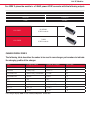
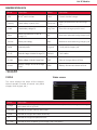
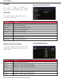
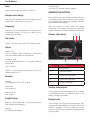
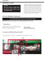
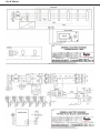
HAWKER MODULAR CHARGERS
®
KEEP ON GOING!
EVEN WHEN PART OF
THE TEAM IS MISSING...
Service manual
Life IQ Modular
TM
Life IQ™ Modular
The modular range is based on the modular concept made of universal power bricks
allocated into different cabinet sizes in order to achieve the required output power.
For 1-phase the module is a 1kW power AC DC converter
TC1= 1-phase 230 Vac
VDC
Ampere DC/ module
12
36A
24
36A
36/48
25/18A
The modules are installed into:
3 bay cabinet up to 3KW
6 bay cabinet up to 6kW (future development)
3 bay cabinet (for chargers up to 3kW)
6LA20650
12V
1kW module
6LA20629
24V
1kW module
6LA20635
48V
1kW module
Life IQ Modular
TM
For 400V 3-phase the module is a 3.5kW power AC DC converter with the following outputs
TC3-3-phase 400 Vac
VDC
Ampere DC/ module
24/36/48
70/65/60A
72/80
40/36A
6LA20651
24/36/48V
3.5kW module
6LA20656
72/80V
3.5kW module
CHARGE PROFILE CODES
The following table describes the codes to be used in new charger part numbers to indicate
the charging profile of the charger
Tech
Charging profile
Display on charger
SAP Code
PzS/PzM/PzB
Slow charge
LOWCHG
PROFILESLOW
PzS/PzB
Heavy duty
HDUTY*
22
PzS/PzM/PzB
Normal duty (std flooded)
STDWL
21
PzS/PzM/PzB
Airmix
PNEU
4
GEL
Gel
GEL
2
XFC
XFC Blocs
XFCBLC
5
AGM
AGM
AGM (or RGT)
6
XFC 2V
XFC 2V
2V-XFC
20
PzM
WL20
WL20
* The charger displays COLD in case of battery temperature below 15°C
9
Life IQ Modular
TM
Profile Description
HDUTY
Heavy duty profile (IONIC). Auto battery capacity matching with
continuous current loops. Default CF 1.15, no need to set CF but
available if required.
GEL
IUI profile, 0.17 to 0.22 C, Auto battery capacity by loops, final current
1%, CF = 1.06. Can manually set battery capacity if required.
AGM
IUI profile, 0.2 C, Auto battery capacity by loops final current 2.2%,
finish time limitation. Can manually set battery capacity if required.
STDWL
Standard (Water Less®) profile. IUI profile 0.2 C, finish CF = 1.10 final
current 5% C, Auto battery capacity matching with phase 1 loop. Can
manually set battery capacity if required.
PNEU
Opportunity charge. Must set battery capacity & daily full charge. IU
profile 0.25 C, finish current 5% C. Can manually set battery capacity
if required.
XFCBLC
For XFC bloc product. Only visible after setting XFCBLC menue item to
ON (all other profiles invisible). Do NOT use for XFC2V product, Profile
IUI, 0.5 C, finish time limitation, with refresh.
2V XFC
XFC 2V product, IUI profile 0.4 C, finish current 1% C, no T° C compensation, weekly autimatic with Wi-IQ®
WL20
Hawker® Water Less® 20 product, IUI profile old WF 200, finish CF=
1.04, needs Airmix
Slow
Slow profile for battery recharge in 9-12 h
IMPORTANT SAFETY INSTRUCTIONS
1.
2. 3. This manual contains important safety and
operating instructions. Before using the battery
charger, read all instructions, cautions, and
warnings on the battery charger, the battery,
and the product using the battery.
This charger has been designed to only charge
flooded, lead-acid batteries. Read and
understand all setup and operating instructions
before using the battery charger to prevent
damage to the battery and to the charger.
Do not touch non-insulated parts of the
output connector or the battery terminals to
prevent electrical shock.
4. During charge, batteries produce hydrogen
gas which can explode if ignited. Never
smoke, use an open flame, or create sparks
in the vicinity of the battery. Ventilate well
when the battery is in an enclosed space.
5. Do not connect or disconnect the battery
plug while the charger is on. Doing so will
cause arcing and burning of the connector
resulting in charger damage or battery
explosion.
6. Lead-acid batteries contain sulfuric acid
which causes burns. Do not get in eyes, on
skin, or on clothing. In cases of contact with
eyes, flush immediately with clean water for
15 minutes. Seek medical attention
immediately.
Life IQ Modular
TM
7. 8. 9. Only factory qualified personnel can
service this equipment. De-energize all AC
and DC power connections before servicing
the charger.
The charger is not for outdoor use.
Do not expose the charger to moisture.
Operating conditions should be 0º to
45º C; 0 to 70% relative humidity.
10. Do not operate the charger if it has been
dropped, received a sharp hit, or otherwise
damaged in any way.
11. For
continued
protection
and
to
reduce the risk of fire, install chargers on
a floor of non-combustible material such as
stone, brick, or grounded metal.
WARNING: The shipping pallet must be removed for proper and safe operation.
TECHNICAL INFORMATION
The nameplate, located on the outside of the charger, should be used to check this
application before installation.
Model
Serial number
Output
Voltage (V)
Current (A)
Operating input voltage
Range (Vac)
Mains & frequency (Hz)
Max input power (W)
Part Number
UK or standard European input plug can be selected by using different part numbers.
Refer to a latest master data for full list
Life IQ Modular
TM
Installation
WARNING: The shipping pallet must be
removed for proper and safe operation.
Location
For maximum trouble-free service, choose a
location which is free of excess moisture, dust,
and corrosive fumes. Also, avoid locations
where temperatures are high or where liquids
will drip on the charger. Do not obstruct the
ventilating openings or the space under the
charger.
AC connection
The user must provide suitable branch circuiprotection and a disconnect method from the
AC power supply to the charger to allow for safe
servicing.
Plug polarity
The charging cable is connected to the DC output
of the charger with the positive lead marked RED.
The output polarity of the charger must be strictly
observed when connecting to the battery (read
warning above). Improper connection will open the
DC fuse.
Grounding the charger
Mounting wall cabinet chargers
The charger must be mounted on a wall or
stand in a vertical position. The lower part of the
charger must be at least 60 cm from the ground
and/or the charger below and the upper part 90
cm from the ceiling. The minimum distance
between two chargers must be 30 cm. The
charger will be installed with the bracket
supplied. See the Wall Mounting Dimensions
section at the end of this manual for proper bolt
pattern.
NOTE
Ambient temperature at all levels cannot exceed
45°C.
Electrical connections
DANGER: Failure to ground the charger
could lead to fatal electric shock. Follow
National Electric Code for ground wire
sizing.
DESCRIPTION OF OPERATION
General
Life IQTM Modular chargers can easily be set to
charge flooded and sealed lead-acid batteries
(including XFC blocs) within the appropriate range of
the cell and ampere-hour rating.
Beginning the charge
To prevent failure of the charger, be sure it is
connected to the correct line voltage.
When a battery is connected to the charger,
the control board senses voltage and after a 15
second delay, the charger starts.
Connecting input power
Charging
WARNING: Make sure the power to
the charger is OFF and the battery is
disconnected before connecting the
input power to the terminals of the
charger.
Connect the input power to the appropriate
terminals, including ground. Follow your local
electrical or National Electric Code in making these
connections.
Charging current is determined by the
battery voltage and interaction of the charger. As
the battery charges, the LCD display will output
various charge parameters including the
percentage of battery capacity.
AC power fail
If the AC power fails with a battery connected to
the charger during a charge cycle, the charger will
reset and start a new charge cycle when power is
restored. All charger settings as well as the timeand
date are preserved.
Life IQ Modular
TM
GLOSSARY
Equalization charging
Charging profile
Equalization charging, performed after normal
charging, balances the electrolyte densities in the
battery’s cells.
The charging profile defines the rate of
current charge over time. The charger
adapts to the battery’s age and level of discharge.
Controlling
the
overcharge
coefficient,
whatever the battery’s discharge level, reduces the
amount of electricity consumed.
Refresh charging
Refresh or maintenance charging enables the
battery to be maintained at maximum charge all
the time that it is connected to the charger.
OPERATING INSTRUCTIONS
2.
Control panel
1.
4.
8.
5.
7.
3.
6.
5.
9.
Display ref Button / LED
Function
Function
1.
Start Stop button
Start-Stop charge
select of active menu
2.
Charger status indicator
Battery available
–
3.
Charger status indicator
Battery in charge
–
4.
Blue LED
AC supply ON (light)
AC supply OFF
5.
Arrows
Navigation buttons
Return to top of list
(press for 2 sec)
6.
Equalization button
Start an equalization
Access a sub menu
7.
Esc
Access a sub menu
Close windows
8.
TFT multicolor screen
Shows details
(refer to LCD display par.)
–
9.
USB port
Download memories
Upload firmware
Life IQ Modular
TM
Ref
Function
1
AC input cable
2
DC output cable
1.
3
Option port
5.
4
Ventilation openings
5
TFT screen
6
Navigation buttons
2.
7
Cable holder (only on single
phase)
4.
4.
6.
3.
1.
7.
Menu Access
LOGs
When the charger is idle, press and hold <ESC>,
the main menu is then displayed. The main menu
is automatically exited after 60 seconds of inactivity
or can be exited voluntarily by pressing the <ESC>
button.
Memorizations
Main menu display
Memorizations display screen
4.
The charger can display the details of the last 300
charge cyles.
The display shows here the charges have been
stored in memory (title line). MEMO 1 is the latest
charge memorized. After memorizing the 300th
charge, the oldest record is deleted and replaced
by the next oldest.
Main menu
All menus are accessed from main menu; a
detailed description of each menu is included in
the next sections of this manual. The menus that
require a password are not displayed until the
correct password has been entered.
The menus provide access to the following
functions:
•
•
•
•
•
•
View status and memorizations
(LOGS icon).
Viewing of faults, alarms, etc.
(CHARGER icon).
USB functions (USB icon).
Setting of date, language and others
(SETTINGS icon).
Management of password
(PASSWORD icon).
Exit main menu (EXIT icon).
Displaying a charge cycle
Proceed as follows:
1. Select a record (MEMO x) using the ▲ /▼
buttons.
2. Display the first history screen by
pressing Enter.
3. Display the second history screen by
pressing ▼.
4. Return to the main menu by pressing Esc.
The charge history is displayed; use the ▲ /▼ to
scroll through the parameters.
Life IQ Modular
TM
Memorization Data
Memo
Information
Memo
Information
S/N*
Wi-IQ® serial number
I end
Current at end of charge
Capacity
Rated battery capacity (AH)
Temp end**
Battery temperature at end of charge
(°C)
U batt
Rated battery voltage (V)
Chg Time
Time of the charge cycle (hh:mm)
Temp
Battery temperature at start of
charge (°C)
AH
Amp-hours returned during charge cycle
Techno*
Battery technology
kWh
Watt-hours returned during charge cycle
Profile
Selected profile
Chg end
Full of partial charge cycle
% init
State of charge at start of charge (%)
Default
Fault codes
U start
Battery voltage at start of charge (Vpc)
SoC
Start of charge date and time
U end
Battery voltage at end of charge
(Vpc)
DBa
Battery disconnect date and time
* Only with Wi-IQ
** Not displayed
STATUS
Status screen
This menu displays the status of the charger’s
internal counters (number of normal and partial
charges, faults by type, etc.).
Status
Information
Charge
Total number of charges. Corresponds to the total of normally terminated charges and charges
terminated with or by faults.
Complete
Number of charges normally terminated.
Partial
Number of charges terminated abnormally.
TH
Number of charger temperature faults.
DF1 etc.
Number of faults recorded by the charger (see Fault codes).
Life IQ Modular
TM
Charger
Charger information display
This
menu
displays
information
on
the
chargers
configuration
and
output
current of the charger and the power modules.
Information
This screen displays the following information on
the charger’s configuration.
Modules*
Information
Profile
Selected charging profile.
Temperature
Programmed temperature.
Capacity
Automatic (default value) or manual.
Max. Current
Maximum current of charger.
Floating
ON or OFF (default value)
Cable
Length and section of DC cable
Equal
Equalize time and current.
Delay Charge
In hours and minutes
Auto Start
ON (default value) or OFF
Modules (password protected)
Charger Module Display
This screen displays the total output current
charger and the output voltage and current of each
power module.
Modules*
Information
IBat
Total charger output current.
MOD1
Module one - output current, output voltage.
MOD2
Module two - output current, output voltage.
MOD3
Module three - output current, output voltage.
MOD4
Module four - output current, output voltage.
MOD5
Module five - output current, output voltage.
MOD6
Module six - output current, output voltage.
MOD1 = leftmost module location (numbering from left to right)
Life IQ Modular
TM
USB
Region
This menu provides access to the USB function.
The charger can store charging data in a USB
memory and update software.
Select the format for date, metric (EU) or
imperial (US) units for temperature, length, and
cable gauge.
Record memo
Display
This function enables the storage of charge
memorizations and the status data. The file, in
CSV format (useable with memoreport or excel),
will be stored in the USB stick under the name:
MDDDHHMM.CSV with
M: For memorization
DDD: Day of the year
HH: Hour of file creation
MM: Minute of file creation
Set screen saver function.
Update software
Update chargers internal software. The software is
provided by EnerSys.
Save setting (password protected)
Record the charger configuration on a USB stick.
Restore setting (password protected)
Upload a configuration from a USB stick to the
charger. This function allows to configure easily
several chargers with same configuration.
Parameters
Date/time
Sets date and time of the charger. The clock has a
battery backup which will preserve the time when
power to the charger is off.
Daylight savings
Enable or disable automatic clock adjustment
for daylight savings time. When enabled, seasonal time change is adjusted automatically. The
charger must be powered up at the time of the
change for it to take effect.
Language
Selects the language displayed in the menus.
Screen saver
Enable or disable the screen saver function.
Delay
Set the time the screen stays illuminated. The
delay time is ad justable in minutes up to 1 hour and
59 minutes.
Password
This is where the password is entered to gain
access to service level menus by authorized
EnerSys service personal.
Life IQ Modular
TM
Required setup – The following parameters must be set including date and time:
Parameters \ daylight savings
EUROPE
Parameters \ display \ screen saver
ON
Parameters \ display \ time
00H15
Parameters \ serial number
PER ORDER
Configuration \ charge \ charge delay \ type
OFF
Configuration \ charge \ charge delay \ value hour/delay
00H00
Configuration \ battery \ cap manu auto
AUTO
Configuration \ equalization \ time
06H00
Configuration \ equalization \ delay
00H00
Configuration \ equalization \ frequency
NEVER
Configuration \ equalization \ refresh ON/OFF
OFF
(Default factory ship configurations)
Charge
Profile
Daily charge (N/A for EMEA)
To select the right charging profile for the
application: LOWCHARGE , HDUTY, STDWL, GEL,
AGM, XFC2V, XFCBLC, WL20, PNEU
On/Off – Sets daily charge on or off.
Daily Chg Start – Sets daily charge start time.
Daily Chg End – Sets daily charge end time.
®
Without Wi-IQ :
Profile selected will be used. Values stored
in the battery menu, such as capacity and
temperature, are used to determine key
charging parameters. Make sure these values
match the battery to be charged or the battery
may be over or under charged which will result in
decreased battery life or performance.
With Wi-IQ:
The appropriate profile for the battery technology
will be selected at the start of charge. Battery
capacity and temperature will also be transmitted
to the charger control.
Charge delay
Type - sets OFF, DELAY (default value), or time of day.
Value hour delay - sets the amount or time of day for
the delay (00:00 to 24:00).
Delay: start of charge is delayed for the amount of
time stored in VALUE (0 to 24 hours) (default value =
0h00mn)
Time of day: charge will not start until the time of
day stored in VALUE (24 hour format).
Block out charge
On/Off – Sets block out charge on or off (default
value).
Block out Start – Sets daily charge start time.
Block out End – Sets daily charge end time.
Conditional charge
Set conditional charge %.
The charger will only commence the charge if
the battery has reached the limit of depth of discharge (DoD) of more than x%. For example if
the user wants to charge the battery only if it is
discharged more than 30%, the parameter 30
has to be entered in the conditional charge. The
00% value disables the function (default value).
It is recommended to select a value between 0 and
30% DOD.
Floating
On/Off- Sets float mode on or off (default value).
Current – Sets float current.
Voltage – Sets float voltage.
Life IQ Modular
TM
This feature can be turned ON or OFF depending
on the application. A float charge at the end of
standard charge is intended to compensate for
consumption by the truck electronics that are left
on when truck is not used (typically AGV). The
parameter VOLTAGE is in mVpc (millivolts per
cell) determines the maximum float voltage. The
parameter CURRENT has to be set to according
to the truck electronics consumption. The current
will automatically decrease to keep the battery
voltage at the maximum defined by the VOLTAGE
parameter.
Battery temperature
This parameter adjusts the regulation voltages on
the charging profile (values between –15°C and
+45°C, default value is +20°C).
Without Wi-IQ: Defines the average operating battery temperature
before the charge. It is recommended the average
electrolyte temperature be entered, especially in
cold areas.
With Wi-IQ:
Set battery rest time in hours (default value is 0).
The battery operating temperature will be
automatically transmitted from Wi-IQ.
The
battery temperature will be analyzed during the
charge; if it increases too much, the charger will
stop to prevent any possible damage.
Refresh On/Off (only with HDUTY profile)
High temperature
Sets refresh mode on or off (default value).
Defines a battery temperature safety limit (default
value is +65°C).
Battery rest
Imax (high level password)
Sets charger maximum output current.
Without Wi-IQ:
not used.
With Wi-IQ:
Battery
If the battery temperature, during the charge,
reaches the programmed limit, the charger will
stop the charge and wait until the temperature
decreases.
NB cells
Sets number of battery cells. Automatic mode is
compatible only with multi-voltage products.
Cable
Cap Manu/Auto
Length
When in HDUTY mode, the charger can estimate
the capacity of the connected battery automatically
“Auto” or the charger will use the capacity entered
manually “Manu” in the Capacity menu.
Select the length of DC cables from the charger to
Capacity
Section
Sets the DC cable gauge: From 6 to 95 mm2.
®
Without Wi-IQ : Battery AH capacity used by the charger (Cap
Manu/Auto must be set to “Manu” ) to determine
start and finish rates.
With Wi-IQ: the battery terminals in 1m to 15m.
The battery AH capacity will be automatically
transmitted from Wi-IQ.
Equalization
Current
This defines the equalization or desulphation
current for a manual start.
Life IQ Modular
TM
Time
EasyKit On/Off
Set ON or OFF (default value) the option.
Sets the equalization time from 1 to 48 hrs.
Charging the Battery
Delayed start (delay)
Sets the delay between the normal charge and the
equalization charge from 0 hr to 23 hrs.
Frequency
Selects one or several periods for carrying out the
equalization charge. The user can select one or
several days per week.
At this point, the charger should have been set up by
a qualified service person. Charging can only begin
with a battery of the proper type, capacity and voltage connected to the charger.
With the charger in wait mode (no battery
connected) and without pressing the Stop/Start
button, the display will show the following information:
Charger idle display
1. 2.
3.
Idle mode
ON/OFF: sets idle mode ON or OFF (default value).
Option
Options Test
Turns on Battery Status (Red/Green), Electrovalve
and Airmix output briefly to test operation.
Electroval. Time
Sets the electrovalve time on in seconds (default
value is 60s).
Com IQ On/Off
ON/OFF : set the communication with Wi-IQ s ON
(default value) or OFF.
5.
Ref
Description
1
Charger type
2
Firmware version
3
Selected charge profile
4
System time and date
5
Connect the battery
4.
®
Network
Protocol
Set a protocol to Jbus, LAN, or BFM
Baud Rate
Sets baud rate
Starting charge cycle
Address JBUS
Sets address
The charger will start automatically when a battery
is connected or push the Stop/Start button if the
battery is already connected.
EasyKit Param
Allow to communicate with an easycontrol device
(with external easykit option).
Address
Set a the easykit address
Delayed start
If the charger was programmed for delayed start,
charging will begin following that delay. When the
battery is plugged in to the charger, the display
shows the time remaining before the programmed
charging starts.
Life IQ Modular
TM
Count down display
®
Without Wi-IQ
If the Wi-IQ adapter is not enabled or no
Wi-IQ are in range, effective charging
starts after a 15 seconds countdown.
The
charger uses Profile, Capacity, and Temperature
settings programmed in the Configuration menu.
With Wi-IQ
If a Wi-IQ adapter is present and one or more
Wi-IQ is in range, the charger will turn on and
apply current to the battery. The display will
show “SCAN” followed by “LINK”. This routine
determines which Wi-IQ in range is one the
battery the charger is connected to. Once the charger makes the determination it downloads data from
Wi-IQ, displays the battery S/N, updates the profile,
capacity, and temperature for charging, and starts
the main charge.
Charge display
A few moments into the effective charge, the
display will begin alternating between the following
charging information:
Charge screens
End of charge display
End of charge without equalization
The green complete LED comes on after proper
end of charge. The green complete LED is on and
the display shows AVAIL. The display alternates
between:
•
•
Total charging time.
Amp/hrs restored to the battery.
Any other lit LED indicates a problem during
charging. Please refer to paragraph Control
panel for more information. If the battery remains
plugged in and refresh charge has been enabled,
refreshes will occur to maintain an optimal charge.
The battery is now ready for use. Push the Start/
Stop button before unplugging the battery.
End of charge with equalization
An equalizing charge can be started manually or
automatically.
Ref
Function
1
Charge info
2
Charge voltage ( total V and V/c)
3
Charge time
4
Battery temperature
5
Battery ID
6
7
8
9
10
11
12
13
14
Wi-IQ warnings
USB connection
Charge Ah
Charger type and charging profile
% of charge
Charge current
Equal mode
Date / time
Wi-IQ Link
Life IQ Modular
TM
Manual start
1.
At the end of charge (green LED on or
flashing), press on the <EQUALIZE>
button. The equalize button can also be
pressed any time during the charge and
an equalize charge will be started after
charging is complete.
NOTE: When an equalize is manually
started, the output current will be
set to the value saved in the charger
configuration. The factory default
depends on the product configuration.
2. The start of the equalization charge is
indicated by the message EQUAL. During
the equalization charge, the charger
displays the output current and alternating,
the battery voltage, voltage per cell,
remaining time.
3. The battery will be available when the green
LED comes back on and the display shows
AVAIL.
4. The battery is now ready for use. If the
battery
remains
plugged
in
and
refresh
charge
has
been
enabled, refreshes will occur to maintain an
optimal charge. Push the ON/OFF button
before unplugging the battery.
Automatic start
If an equalization day has been programmed in
Charger configurations the equalization charge will
start automatically on the programmed day of the
week after charging is complete.
Note: The factory default equalization
is 6 hours and the day occurrence
has to be set up.
The battery will be available when the green LED
comes back on and the display shows AVAIL. The
battery is now ready for use. If the battery remains
plugged in and refresh charge has been enabled,
refreshes will occur to maintain an optimal charge.
Push the Start/Stop button before unplugging the
battery.
OPTIONS
Ensure when using an optional equipment
(airmix, BSI, PLC …) that the second ribbon cable is
connected between the display and backplane
boards.
The correct operation of the option can be tested
through the menu (option test).
Life IQ Modular
TM
LCD fault messages
Fault
Cause
Remedial action
No display
and Blue
LED off
No mains supply.
Check the power supply and the input fuse(s).
DF CURRENT
Battery available.
–
DF1*
Charger fault.
Check the power supply voltage.
DF2*
Charger fault.
Check that the battery is correctly connected
(that the cables are not reversed) and check
the output fuse
DF3*
Unsuitable battery.
Battery voltage too high or too low. Connect
the correct battery to the charger
DF4
The battery has been discharged more than
80% of its capacity.
Charging continues
DF5
Battery requires inspection.
Check the charging cables (cross-section too
small), the terminals (oxidization, not tight)
and the battery (defective cells).
DF7
Pneumatic mixing air circuit fault (the red
light flashes).
Check the air circuit (pump, tubing).
TH*
Thermal fault resulting in interruption of
charging.
Check that the fan(s) is (are) working correctly
and/or that the ambient temperature is not
too high or whether there is poor natural
ventilation to the charger.
MOD TH
Alternating with charge parameters - one or
more module in thermal fault - the charge
process continues - the faulty module(s) is
(are) displayed + red led flashing.
Check that the fan(s) is (are) working correctly
and/or that the ambient temperature is not
too high or whether there is poor natural
ventilation to the charger. If all modules are in
thermal fault, a TH* fault will follow.
MOD DFC
Alternating with charge parameters - one
or more module in DF1 fault - the charge
process continues - the faulty module(s) is
(are) displayed + red led flashing.
Check power supplys. If all modules in DF1
fault a DF1* error will follow (blocking fault).
DEF ID
Blocking fault - one or more module are not
compatible with the charger configuration
(for example 24V charger with one 48V
module). This can happen if the user
replaces one module with another one with
a different voltage setting.
Use correct module.
* A blocking fault preventing charging from continuing.
Refer to the Technical Characteristics sheet joined to the charger.
Life IQ Modular
TM
MAINTENANCE & SERVICE
The charger requires a minimum of maintenance.
Connections and terminals should be kept clean
and tight. The unit (especially the module heatsink
and fan) should be periodically cleaned with low
pressure air to prevent any excessive dirt build up
on components. Care should be taken not to bump
or move any adjustments during cleaning. Make
sure that both the AC lines and the battery are
disconnected before cleaning. The frequency of this type of maintenance depends on the
environment in which this unit is installed.
CAUTION:
There are dagerous voltages within
the battery charger cabinet. Only
qualified personnel should service
this battery charger.
TESTING OF COMPONENTS SINGLE PHASE
Only qualified personnel should service this battery charger.
IMPORTANT: Disconnect battery and turn AC power OFF before servicing.
1. DC output fuse
Disconnect the AC power and the battery before
opening the door. Check of output fuse is carried
out with the multimeter in Ω position.
0 Ω = fuse Ok
Infinity = replace the fuse
Part number : 6LA10465 = DC fuse (fusible DC)
DC output fuse & DC cables - torque M6 to 7Nm and M4 to 1.5 Nm
7 Nm
1.5 Nm
Life IQ Modular
TM
2. Display board and door
CAUTION: Use an anti-static wrist strap
when removing and replacing circuit
board assemblies.
Part
Description
Enersys Part no.
Kit porte
Door kit 3x1kW IQ
3543031
If a fault on the display, control board or
external door occurred, replace the full door with
Kit 3543031.
REMOVAL
REPLACEMENT
Please follow these steps to remove a display
board.
1. 2. 3. 1.
2. 3. 4. Touch your finger to a ground to remove
any static charge.
Unplug
all
connectors
from
the
display board. Some connectors maybe
secured by screws.
Unscrew the hinges on the side.
Remove the door.
Align the door kit to the in proper position.
Reallocate screws in on the side hinge
(torque to 1Nm).
Reconnect the ribbon cable(s).
ENSURE TO PROGRAM THE CHARGER CORRECTLY FOR THE APPLICATION.
THE CHARGER SERIAL NUMBER HAS TO BE SET UP IN THE MENU.
Life IQ Modular
TM
3. Module test and replacement
1.
2. 3. 4. Operation
LED
Init
Rolling green/red alternatively for 6 seconds
Module in stand-by
Short green pulses
Module in operation
Green fixed
Fault
Red ON or flashing – refer to charger display
6LA20650
12V
1kW module
6LA20629
24V
1kW module
6LA20635
36/48V
1kW module
Unplug AC plug and DC from battery.
Wait till blue light on the screen is off.
Touch your finger to a ground to remove
any static charge.
Remove top and bottom screw.
5. 6. 7. Pull the module out from its guide.
Place the new module (ensure to use an
appropriate module).
Screw the top and bottom screw back.
Module bottom and fan
Life IQ Modular
TM
Module heatsinks
Every module has an unique serial number
to be used for eventual claims
COMPONENT LOCATIONS 1-phase
Aux.
AC fuse
AC
cable
Ribbon
cable for
options
Display
ribbon
cable
Module
1 Slot
DC
Cables
Module
2 Slot
DC
Fuse
Module
3 Slot
Life IQ Modular
TM
TESTING OF COMPONENTS 3-PHASE
Only qualified personnel should service this battery charger.
IMPORTANT: Disconnect battery and turn AC power OFF before servicing.
1. AC input cabinet fuse
1. 2. Disconnect both mains and
battery from the charger.
Remove the top cover of the charger.
2 and 4-bay cabinets = 30A time delayed fuses (10x38)
6-bay cabinet = 40A time delayed fuses (14x51)
3. 4. 5. Replace the faulty fuses.
Replace the top cover.
Test the charger.
Refer To Spare
part hub for Part
numbers
2. AC input module fuse
DC fuse Bussmann FWH-010A6F
1. 2. 3. 4. 5. Disconnect both mains and battery from
the charger.
Open the charger door.
Unscrew and extract the faulty module.
Remove the top lid of the module.
Test the voltage across the M7 MOV with a
multimeter (diode position).
>
~0.7V => replace the faulty fuse(s)
0.0 to 0.55V => replace the module
3553651
6. Replace the faulty fuses located as in
picture.
7. Replace the top lid.
8. Replace the module.
9. Test the charger.
Life IQ Modular
TM
3. DC Fuse
DC fuse Bussmann#125LET (24/36/48V module)
3553635
DC fuse Bussmann#80LET (72/80V module)
3553643
Every module has its own output fuse. If one
module fails due to a burned fuse (refer to internal
LEDs meaning above):
1. 2. 3. 4. Open the front door of the charger.
Unscrew the faulty module and extract it.
Remove the metal cover on the side.
Replace the DC output fuse – torque to 7Nm.
5. 6. 7. Replace the metal cover and screw it back.
Replace the module in the charger.
Test the charger.
4. Display board and door
Kit display
2/4 bay IQ
3553579
Kit display
6 bay IQ
3554201
1. Remove the top lid of the charger by
unscrewing the two main top screws and
slide of.
2. Disconnect the ribbon cable.
Life IQ Modular
TM
3.
Remove bottom screws of the display panel.
4. Remove the front panel.
5. Reconnect the new panel by screwing back
all the screws and reconnecting the ribbon
cable.
ENSURE TO PROGRAM THE CHARGER CORRECTLY FOR THE APPLICATION.
THE CHARGER SERIAL NUMBER HAS TO BE SET UP IN THE MENU.
5. Module test and replacement
Operation
LED
Init
Rolling yellow/green/red alternatively for 6 seconds
AC power OFF or charger idle mode ON or
module in fault
Yellow OFF
In all the following cases, yellow led on
1.
2.
3. 4. 5. Module in stand-by
Short green pulses
Module in operation
Green fixed
Fault
Red or flashing – refer to charger display
6LA20651
24/36/48V
3.5kW module
6LA20656
70/80V
3.5kW module
Unplug AC and DC plugs from the battery. Wail till blue light on the screen off.
Touch your finger to a ground to remove
any static charge.
Open the charger door.
Unscrew the module.
6. 7. 8. Pull the module out from its guide.
Place the new module (ensure to use an
appropriate module).
Screw the top and bottom screw back.
Life IQ Modular
TM
Life IQ Modular
TM
TECHNICAL SPECIFICATION - SINGLE PHASE
Specifications
Units
Nominal input voltage
Vac
Frequency
Hz
Max current draw @ 230Vac
A
AC input cable section
AC input cable length
1kW
12V
Battery voltage
2kW
24V
36/48V
36/48V
Battery cables section
mm2
Battery cables length
m
4.8
5.1
9.6
36
25/18
72
Dimensions (HxWxD)
Weight with airmix
Dimensions (HxWxD) with airmix
15.3
50/36
108
75/54
25
3
IP21
°C
0°C to +45°C
0.99
W
≤10
Multiline TFT
Display
Weight
14.4
1.5
36
Power factor
Idle mode
10.2
3 x 1.5
IP protection
Operating temperature
36/48V
50/60
2.4
m
Adc
24V
230V +/- 10% / 1ph
mm2
Max output current @ 230Vac
3kW
24V
kg
6.0
7.0
mm
8.0
344 x 250 x 182 (no brackets)
kg
9.0
10.0
mm
11.0
435 x 286 x 185 (no brackets)
3 bay (1 module)
Cabinet
3 bay (2 modules)
3 bay (3 modules)
3 bay cabinet
Top view
Technical specification - Three PHASE
Specifications
Units
Nominal input voltage
Vac
Frequency
Hz
Max current draw @ 400Vac
A
AC input cable section
AC input cable length
3.5kW
24/36/48V
Battery voltage
7kW 7kW
72/80V
24/36/48V
10.5kW
72/80V
24/36/48V
14kW
72/80V
24/36/48V
Battery cables section
mm2
Battery cables length
m
5,6
11.2
11.2
16.8
16.8
4 x 2.5
22.4
40/36
140/130/120
80/72
210/195/180
120/108
35
Dimensions (HxWxD)
Weight with airmix
Dimensions (HxWxD) with airmix
Cabinet
2 and 4 bay cabinet
22.4
28.0
28.0
29.8
33.6
320/320/320
240/216
4 x 6.0
280/260/240 160/144 320/320/300
200/180
70
95
3
IP21
°C
0°C to +45°C
0.95
W
≤10
Multiline TFT
Display
Weight
72/80V
2
70/65/60
Power factor
Idle mode
24/36/48V
4 x 4.0
IP protection
Operating temperature
72/80V
50/60
5.6
m
Adc
21kW
24/36/48V
400V +/- 10% / 3ph
mm2
Max output current @ 400Vac
17.5kW
72/80V
kg
26.0
29.5
mm
kg
33.5
37.0
44.5
508 x 335 x 352
28.0
mm
31.5
35.5
39.0
508 x 335 x 352
2 bay (1 module)
2 bay (2 modules)
4 bay (3 modules)
6 bay cabinet
48.0
508 x 485 x 352
46.5
50.0
508 x 485 x 352
4 bay (4 modules)
6 bay (5 modules)
6 bay (6 modules)
Life IQ Modular
TM
Please refer to the website address for
details of your nearest EnerSys®
office: www.enersys-emea.com
© 2015 EnerSys. All rights reserved.
All trademarks and logos are
the property of or licensed to
EnerSys and its affiliates
unless otherwise noted.
03.2015 - Subject to revisions without prior notice. E&OE
EnerSys EMEA
EH Europe GmbH
Löwenstrasse 32
8001 Zürich
Switzerland
Phone: +41 44 215 74 10
Fax: +41 44 215 74 11
www.enersys-emea.com