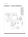
1
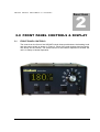
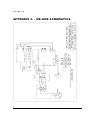
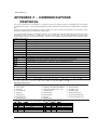
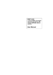
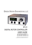
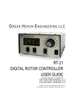
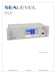
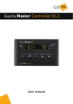
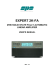
UB-ONE DIGITAL ROTATOR CONTROLLER USER GUIDE Software Revision 3.9 UltraBeam antenna rotor Strada Dei Gerbidi, 6 14019 Villanova D’Asti – Italy www.ultrabeam.it RADIO AND TELEVISION INTERFERENCE This equipment has been tested and found to comply with the limits for a Class B digital device, pursuant to Part 15 of the FCC rules. These limits are designed to provide reasonable protection against harmful interference in a residential installation. This equipment generates, uses and can radiate radio frequency energy and, if not installed and used in accordance with the instructions, may cause harmful interference to radio communications. However, there is no guarantee that interference will not occur in a particular installation. If this equipment does cause harmful interference to radio or television reception, which can be determined by turning the equipment off and on, the user is encouraged to try to correct the interference by one or more of the following measures: Reorient or relocate the receiving antenna. Increase the separation between the equipment and the receiver. Connect the equipment into an outlet on a circuit different from that to which the receiver is connected. Consult the dealer or an experienced radio/TV technician for help. Changes and Modifications not expressly approved by the manufacturer or registrant of this equipment can void your authority to operate this equipment under Federal Communications Commissions rules. NOTICE The Controller UB-ONE is produced by Green Heron Engineering and is customized for the exclusive use of the new rotor Ultrabeam. UltraBeam reserves the right to make changes for product improvement or manufacturing, without notice or any obligation to update units already sold. WARRANTY This product is warranted to be free of defects in materials and workmanship for 1 year. We will repair or replace, at our option, any equipment proven to be defective within the warranty period. All warranty work is Ultrabeam Italy. This warranty is exclusive of abuse, misuse, accidental damage, acts of God or consequential damages, etc. UltraBeam shall not exceed the original purchase price of the equipment. This unit is normally supplied with a 3.5 Amp Slo-Blo 5x20 mm fuse in the rear panel fuse holder. If it is necessary, replace only with: 115 VAC – 4 amp SB max 230 VAC – 2 amp SB max V E R S I O N 1.0 1.2 1.3 1.4 1.5 1.6 1.7 2.0 2.1 2.2 3 I N F 0 R M A T I O N : QUICK START GUIDE ................................................................................................................................................. 1 VERIFY 115/230 VAC SWITCH................................................................................................................................ 2 SET THE OFFSET VALUE (DEFAULT IS NORTH CENTER, OFFSET = 180) .............................................................. 2 CONNECT THE UB-ONE TO ROTATOR............................................................................................................... 3 CONSIDERATION ABOUT THE CHOICE OF THE CABLE .................................................................................... 3 CALIBRATE YOUR ROTATOR ................................................................................................................................ 4 SPEED AND RAMP ADJUSTMENTS ...................................................................................................................... 5 FRONT PANEL CONTROLS & DISPLAY .................................................................................................................. 6 FRONT PANEL CONTROLS .................................................................................................................................... 6 FRONT PANEL DISPLAY ......................................................................................................................................... 9 3.0 SETUP MODE ............................................................................................................................................................... 10 3.1 SETTING OTHER PARAMETERS ............................................................................................................................ 10 4.0 OPERATING HINTS & ADVANCED FEATURES ......................................................................................................... 14 4.1 OPERATING HINTS ................................................................................................................................................. 14 4.2 COMPUTER CONTROL OF UB-ONE ..................................................................................................................... 15 4.3 MASTER/SLAVE (M/S) MODE................................................................................................................................. 15 4.4 M/C AND S/C MODES .............................................................................................................................................. 16 4.5 FIRMWARE UPDATES ............................................................................................................................................... 17 4.6 CHANGING THE VANITY DISPLAY, MOTION TIMEOUT, SECURITY LOCK .................................................... 18 4.7 ALTERNATE OFFSETS (FIRMWARE 1.6 AND LATER) ............................................................................................. 18 4.8 ADVANCED OPTIONS (FIRMWARE 1.6 AND LATER) ............................................................................................... 18 5.0 ERRORS AND TROUBLESHOOTING .......................................................................................................................... 21 APPENDIX C – UB-ONE SCHEMATICS ............................................................................................................................. 23 APPENDIX C – UB-ONE SCHEMATICS ............................................................................................................................. 24 APPENDIX F – COMMUNICATIONS PROTOCOL ............................................................................................................. 25 APPENDIX G – SETUP UTILITY.......................................................................................................................................... 26 APPENDIX H – MEASUREMENT ........................................................................................................................................ 28 iii U B - O N E Q U I C K S T A R T G U I D E Section 1 1.0 QUICK START GUIDE M os t Pr o p Pi t c h r ot at or s do no t h a ve me c h a ni c al l i m i t s , DO NO T at t e m pt r ot at i o n o t he r t ha n w i t h t he CW a n d CC W p us hb ut t on s be f or e ca l i br at i o n ha s b ee n c om pl et e d, a nd t h e s of t l i mi t s a re pr o ve n t o b e w or k i ng a s d e s i r e d. TERMINOLOGY The following terms may be unfamiliar to new users of the UB-ONE and are defined here for clarity. It is important to understand their meanings, as they will be used frequently during configuration and setup tasks: TERM DEFINITION Endpoints The counter-clockwise (CCW) and clockwise (CW) endpoints refer to the ends of rotation that would normally occur with a system that rotates exactly 360 degrees. Note that CCW and CW endpoint headings are the same, but at opposite ends of a 360-degree arc (with the center-ofrotation being 180 degrees from either endpoint). Over-Travel Rotation beyond the normal endpoints of 360 degrees. Point-and-shoot This action refers to setting a direction with the front panel Heading Knob and allowing the UB-ONE to execute this move automatically, stopping at the selected heading. Soft Limits These are travel limits that can be programmed into the UB-ONE. The effect is similar to the mechanical limits built into many Rotators, but it is achieved inside the controller and is fully programmable to allow overtravel (if supported by the Rotator) or to reduce travel for installations requiring limiting the rotation to less than 360 degrees (a sidearm antenna mount, for example). If a Rotator does not have mechanical endpoints, this feature helps avoid turning the Rotator past a desired range. Ramp-up/Ramp-down This UB-ONE feature provides gradual startup and shutdown of Rotator power to reduce stress on towers, antennas and Rotators. This is 1 U B - O N E Q U I C K S T A R T G U I D E achieved by pulse-width-modulating the operating voltage for the Rotator. Ramp-up is utilized for all starts, and ramp-down is used on all stops. (The ramp down is abbreviated for manual button releases, CANCEL or computer ‘stop’ commands) Offset This value sets the desired CCW Endpoint which then indirectly sets the Center of Rotation. A value of 180 is a North Center, a value of 0 is a South Center. NOTE: The compass headings of 360 and 0 degrees refer to the same direction. There are cases where the SETUP display may read 360 degrees instead of 0, but it refers to the same compass direction of North. During normal operation, the heading display will always display within the range of 0 to 359.9 degrees. 1.2 VERIFY 115/230 VAC SWITCH • • This switch MUST be set to the choice that is correct for the primary (mains) voltage that will power your UB-ONE. If the position of the 115/230 VAC switch is moved, check the rear panel fuse for proper value. The fuse is an International Standard GMA 5mm x 20mm type, and should normally be a 3.15 or 4A Slo-Blo fuse for 115 VAC line, or a 2A Slo-Blo fuse for 230 VAC line. Connect the power cord to the rear panel receptacle and set the front panel power switch to ON. You should first see the start-up message, then the software version number, followed by the operating display. 1.3 SET THE OFFSET VALUE (default is North Center, OFFSET = 180) The offset value is the number of degrees that your counter-clockwise (CCW) endpoint is from true North. It is normally equal to the compass heading of your CCW endpoint. For example: If your center-of-rotation were South (with the CCW endpoint at North) then your offset would be 0. If your center-of-rotation were North (with your CCW endpoint at South) then your offset would be 180 degrees (Default). 1.3.1 Configure the desired Offset value 1. Enter SETUP mode • • Press and hold down the SETUP/ITEM button for 2 seconds Release the SETUP/ITEM button when SETUP appears on the display. 2. Choose the OFFSET parameter • Repeatedly press and release the SETUP ITEM button until Offset is displayed The currently set offset will be displayed after the equals sign (=). The bottom line on the display will indicate NEW VALUE = XXX. o o 3. Set the OFFSET parameter for your Rotator • Rotate the heading knob until the desired OFFSET is displayed after NEW VALUE = on the display. NOTE: For North Center – OFFSET = 180 degrees (Default) 2 5 U B - O N E Q U I C K S T A R T G U I D E For South Center – OFFSET = 0 degrees • • 1.4 Press the CHANGE button to store the New OPTION. Press the SAVE button to exit the SETUP menu. CONNECT THE UB-ONE TO ROTATOR Remove power from the unit before making c o n n e c t i o n s IT IS EXTREMELY IMPORTANT THAT THE WIRE TO THE MOTOR COMMON IS NEVER CONNECTED TO GROUND, OR ALLOWED TO SHORT TO GROUND. Rotor color pin-out RED PWM motor voltage BLACK PWM motor voltage WHITE sensor return GREEN sensor out BROWN sensor ref 1.5 Controller 1 CW 2 CCW 3 GND 4 POS 5 REF CONSIDERATION ABOUT THE CHOICE OF THE CABLE The electric connection between the controller and the motor needs a 5 poles cable: - PIN 1-2 MOTOR * - PIN 3-4-5 ENCODER (section wire 0.25 / 0.35mm) * The section of the 2 wire powers are very important. The right section to use depends on the length of the cable needed for the installation and the rotor needs to provide. The new UB-ONE rotor is capable of a maximum torque of 470 Nm, however, for many antenna systems, significantly lower powers are sufficient. For these reasons it is enough to fix the correct section of the cable to use in your own installation and in any case we suggest (for the 2 motor cables) a minimum section of 2 mm. which you can increase if necessary . 1.5.1 Considerations to set up the ramps and speed The power of the rotor is in function of the rotation speed which is set in the controller: • Min speed 2: minimum torque power. • Max speed 10: maximum torque power. The minimum speed and maximum speed (cruise) determine the start and stop of the ramps. 3 5 U B - O N E Q U I C K S T A R T G U I D E MAX SPEED The choice of the maximum speed is closely related to two important factors: the wind and the antenna size. In the absence of wind you will have a freedom of choice. In windy conditions you have to use the maximum speed that allows you to rotate your antenna without any problems, normally a speed 8 offers considerable power. In the presence of strong wind you may have to remove the ramp by setting the value of the minimum speed equal to the maximum speed. MINIMUM SPEED The minimum speed and the ramp time determine the start but it is more important to stop the antenna: a speed minimum 2 and a time ramp-5 will slow down your antenna in a very soft way, this set up is suggested where antennas have very long elements (22-25 mt.) For antennas with medium, small elements (10-15 mt.) a minimum speed of 3-4 is the best suggestion. Based on these considerations everyone will find the best settings according to his antenna system and the wind speed. The controller UB-ONE will allow you to always find the most appropriate set up. 1.6 CALIBRATE YOUR ROTATOR DO NOT use the Point-and-Shoot knob before your Rotator is calibrated. Rotators without mechanical limits may be damaged or Rotator loops may be exceeded if unintended over-travel occurs. Always enlist a spotter or take extra precautions until you have calibrated your unit and verified that the limits are operating correctly! If you have not yet installed your antenna or were already at North (South if OFFSET = 0), then make sure your display reads 0 degrees (180 if OFFSET = 0). If so, you are done and ready to go. If you had changed the Divide Ratio, or your antenna is already up, fastened to the mast at something other than your center of rotation, then simply: 1.6.1 1.6.2 Enter SETUP (press and hold CANCEL until SETUP appears) and turn the knob to change the CALIBRATION – New Value equal to your antenna’s current direction. Press CHANGE, and then SAVE. Make sure that your coax loops are correctly positioned to allow full rotation once your system is up and calibrated. 4 5 U B - O N E 1.7 Q U I C K S T A R T G U I D E SPEED AND RAMP ADJUSTMENTS Each system is unique due to the length & size of the wires to power the prop pitch motor. The best MIN SPEED to use is the lowest one that will cause the rotator to turn without causing a “POSITION FAIL ERROR.” This will provide the minimum torque on the antennas & tower, and result in the least amount of overshoot when arriving at the desired target headings To find the MIN SPEED for your system, try setting the MIN SPEED value to a low number like “1 or 2” and then try to rotate by pressing one of the manual CW or CCW buttons. If the controller display does not show movement on the display and then shows the POSITION FAIL error, then the value is too low. Change to the next higher MIN SPEED value and test for rotation again. When the rotator turns without producing the POSITION FAIL error, you have found the best MIN SPEED for your system. You may find that a RAMP value, that works fine during warm parts of the year, is too low for cold weather. If you get POSITION FAIL errors in cold weather, increase the MIN SPEED one number at a time until it rotates properly. This may require a RAMP adjustment to longer ramps. To find the proper RAMP Value, you need to have someone rotate the system 90 deg with the point & shoot knob, while you observe how the antenna and tower react to the movement. If the tower and antenna(s) windup and move behind the rotator on “ramp up” and then wind up and oscillate at the end of the “ramp down”, your ramp is too short (RAMP value too small). Increase the RAMP value until the antenna(s) start and stop smoothly without tower/antenna oscillation. The best MAX SPEED is usually 10. This provides the shortest rotation time between headings, and will not cause excess tower/antenna torque and oscillations if the RAMP is correct for the antenna array. 5 F R O N T P A N E L C O N T R O L S & D I S P L A Y Section 2 2.0 FRONT PANEL CONTROLS & DISPLAY 2.1 FRONT PANEL CONTROLS The controls on the front of the UB-ONE include three push buttons, the heading knob and the power switch as shown in Figure 2. Each of the push buttons has two labels, one above and one below. The active function of the buttons depends on whether the unit is in Setup or Normal Operation. 6 F R O N T P A N E L C O N T R O L S A N D D I S P L A Y 2.1.1 Front Panel Buttons—Normal Operation When the UB-ONE is in normal operation, the push buttons function using the labels above the buttons. Table 1 summarizes their functions. Table 1. Button Functions in Normal Operation Button Label CCW Button Function Turns Rotator counter-clockwise (## Ramp-down and creep) CW Turns Rotator clockwise (## Ramp-down and creep) CANCEL In normal operation mode CANCEL can be used in three ways: • A tap of the CANCEL button cancels the current rotation event from the front panel heading knob or computer command. • Holding the CANCEL button down for 2 seconds places the unit into SETUP. • A tap of the CANCEL button toggles in or out of M/C, M/S, or S/C mode to allow a manual operation to be performed. • A tap of the CANCEL button will toggle among the three optional OFFSET values when in the optional OFFSET mode. (see Mode=OFFSET ## tapping the CCW or CW button, while computer or point-and-shoot motion is in progress, will ramp down to Minimum speed but continue to target unless CANCEL is pressed. 2.1.2 Heading Knob—Normal Operation The heading knob on the UB-ONE is used to choose a heading for “Preset/Pointand-Shoot” rotation. The scale is appropriate for either a North or South center-ofrotation. When the knob is moved to the desired heading, the UB-ONE begins Rotator movement automatically. NOTE: The scale is a close approximation of the knob position. The exact position is always shown on the front panel digital display. 2.1.3 Front Panel Buttons—Setup Operation When the UB-ONE is in Setup, the three push buttons function using the labels below the buttons. Table 2 summarizes their functions. Table 2. Button Functions in Setup Button Label Button Function SETUP/ITEM The SETUP/ITEM button has two functions. • Initiate Setup Mode: Press and hold down the button for 2 seconds, release when “SETUP” appears in the display window. • Select the next item in the SETUP menu: Repeatedly press the button until the desired setup item appears on the display. CHANGE Modify the currently selected item to the value shown in the display window as set by the heading knob. SAVE Save changes and exit setup mode 7 F R O N T P A N E L C O N T R O L S A N D D I S P L A Y 2.1.4 Heading Knob—Setup Operation When in SETUP, the Heading Knob is used to select desired values on the display. 2.1.5 Combined Button Functions Additional functions are available when certain combinations of buttons are pushed together. Refer to Table 3 for an explanation of these additional functions. When invoking these functions, lead with the CANCEL slightly ahead of the CW, CCW or both. Table 3. Combined Button Functions Button Combination Function CANCEL+CCW CANCEL+CW Calibrate CCW at CCW endpoint. (Pot position only) CANCEL+CCW+CW Restores all default values to factory settings. Calibrate CW at CW endpoint. (Pot position only) 8 F R O N T 2.2 P A N E L C O N T R O L S A N D D I S P L A Y FRONT PANEL DISPLAY The front panel display (Figure 3) is a multi-function, backlit LCD. Figure 3. UB-ONE Front Panel Display Table 4. Display Fields and Functions Field Name Valid Values Definition Current Heading 000.0 – 359.9 Current Speed 1 – 10 Over-Travel Indicator OT Soft Limit < > Compass heading of antenna in a properly calibrated system. Tenths not displayed for OPTION HAM or T2X While motor is running, this displays the actual PWM speed to the motor. (1 = 10% .. 10 = 100%) Over-Travel outside of the normal endpoints of 360-degree rotation. (Rotators that allow rotation beyond 360 degrees with wider stops, or no stops at all use this.) Rotator has reached the soft limit set in the Rotator SETUP. The UB-ONE 1 will not allow rotation beyond these points. Direction of current Rotation/Movement. Right indicates clockwise; left indicates counter-clockwise. Direction Indicators Knob Position Operating State 0 – 359 MAN PRE REM M/S M/C S/C OF1, OF2 DBG Shows exact position of the heading knob. It is used for choosing a precise setting when doing setup commands or in “point-and-shoot” operation. Manual—Local operation with front panel controls. Preset—Displayed when UB-ONE has sensed movement of the heading knob and a point-and-shoot operation is in progress. Remote—Unit being controlled via the RS-232 line from another device. Master/Slave Mode—Unit connected to other UB-ONE for coordinated operation. Master Counter-Rotate—Connected mode S/C unit can compensate for movement from this unit. Slave Counter-Rotate—Slave unit is compensating for movement from mode M/C unit, such as on a rotating tower, where a specific antenna must maintain its heading. OFFSET MODE—When an Alternate OFFSET is being use to display heading of antenna. Debug—Used for system troubleshooting. Provides continuous display update, and disables NO MOTION and POT Out-of-Range errors. 9 S E T U P M O D E Section 3 3.0 SETUP MODE 3.1 SETTING OTHER PARAMETERS This same sequence that was used to set up the OPTION parameter is used to modify any setup parameter (SELECT, CHANGE, SAVE). It is important to remember that if you change an OPTION parameter, you must SAVE and reenter the SETUP menu to make any other changes TIP: Some menu items can change calculations and affect related options, so it’s a good idea to only change one item at a time until you become familiar with the UB-ONE. For example, changing the CTR divide ratios will change the CALIBRATE, the OFFSET will change the SOFT LIMITS to match, etc. SETUP ITEMS This section provides a detailed description of the options available in the SETUP menu. The parentheses () indicate the option setting(s) under which the item is available. CALIBRATE – This item calibrates the directional display to the physical direction of your antenna. OFFSET – Sets the CCW endpoint for your system in degrees clockwise from true North. The default setting is “180”. This means that the default stops are at South with a North center-of-travel. To set a South center, you would set the OFFSET to “0”. This setting also affects the soft limits within the UB-ONE and repositions them automatically if you change the OFFSET value. • You may have both “South center” and “North center” antennas on the same mast and Rotator. For example, you may wish to put a VHF antenna on South center and HF antenna on North center. You can select which center-of-rotation is to be used by simply changing the OFFSET. • The OFFSET is also useful in a POT system to compensate for mast slippage as a temporary measure until you can re-align correctly. • Mobile “rover” stations can use the OFFSET feature as well. Simply enter the amount of offset depending on how far off your vehicle is parked from a North heading. 10 S E T U P M O D E DELAYS – This sets the delay times enforced by the UB-ONE before allowing a reversal in motor direction, or before the Brake engaged. This delay setting is adjustable in 1 second increments up to a maximum of 6 seconds. MIN SPEED – This sets the minimum speed that that is used for starting and stopping the motor as it ramps up and/or down, 1 to 10 where 1 is 10%… 10 is 100%.. The MIN SPEED setting has no effect when ramps are not used (Min and Max Speed = 10). Generally, this is set to the slowest speed that allows your Rotator to turn reliably, typically 3 or 4 for Prop Pitch motors MAX SPEED – This selects the motor speed, 1 to 11 where 1 is 10%…10 is 100%. For speeds within 1 to 10, ramp-up and ramp-down power is applied to the Rotator. This reduces tower stress on large arrays. Speed 11 forces MIN SPEED and MAX SPEED both to 10 for full speed with no ramp-up or rampdown conditioning. CCW LIMIT – Selects the absolute heading for the CCW soft limit. The soft limit may be set +/- 180 degrees from the normal CCW endpoint. (Normal endpoints apply to systems that allow 360 degrees of rotation with mechanical stops.) CW LIMIT – Selects the absolute heading for the CW soft limit. The soft limit may be set +/- 180 degrees from the normal CW endpoint. (Normal endpoints apply to systems that allow 360 degrees of rotation with mechanical stops.) OPTION – Selects the Rotator type. Described earlier in this section. DIVIDE HI – Selects the first two digits (high order) of the pulse divider. The divider number is equal to the number of pulses in a 360-degree rotation. For example, if your Rotator provides 9576 pulses in 360 degrees, the DIVIDED HI value is set to 95. DIVIDE LO – Selects the last two digits (low order) of the pulse divider. The divider number is equal to the number of pulses in a 360-degree rotation. For example, if your Rotator provides 9576 pulses in 360 degrees, the DIVIDE LO value is set to 76. (Always set the DIVIDE HI first, then the DIVIDE LO.) NOTE: The divide ratio may be set as high as 32,600 in order to support high accuracy, high ratio custom systems. If the ratio must be set higher than 9999 (HI > 99) then the SETUP UTILITY must be used to set the Divide Ratio value instead of the front panel SETUP Mode CAL RANGE (Available only with OPTION = POT) – This is the degree range that the potentiometer calibrate routines will assume for the distance traveled between the CCW and CW calibration points. This value defaults to 360 degrees and should not be changed unless you cannot rotate your antenna full 360 degrees in order to perform the potentiometer calibration. (A sidearm application on a tower may be one example of this.) You can calibrate the Rotator prior to physical installation, or use the CAL RANGE to set this parameter. Refer to Section 5—Advanced Features—for a detailed sidearm calibration procedure. 11 S E T U P M O D E MODE – Selects the operating mode of the UB-ONE controller. • NORMAL Mode – NORMAL mode allows manual control, point-andshoot and computer control via one of the rear panel communication ports. • M/S – Master/Slave Mode, where multiple UB-ONE controllers are linked together. o Usage and Examples: Master/Slave mode allows one UB-ONE to control other UB-ONE controllers via the EIA-232 port. This allows movement of multiple Rotators and antennas to the same heading without having to set each one individually. The M/S MODE is intended for use in controlling stacks of HF monobanders or tribanders that are on different Rotators (or even different Rotator types). It allows the operator to turn the entire stack together or quickly separate them for individual rotation. When you set the MODE to M/S, you may quickly disable or enable the M/S mode by pressing the CANCEL button. o Functionality If you only have a stack of two antennas, each with its own Rotator, either controller may be used to turn the pair. If you have three or more antennas on different Rotators, then one of the controllers must be designated as the Master. The controller designated as the Master is the only one that will turn all of the antennas. The other controllers will only turn the antennas they are directly connected to. Refer to Section 5—Advanced Features—for more detail on M/S operation and EIA-232 connections. • M/C – “Master/Counter-Rotate” Mode o Usage and Examples Master/Counter-Rotate Mode is used for the bottom Rotator (or tower) in a system where two Rotators are used in series along the same “mast”. Examples of this are a Rotator at the top of a rotating tower, or two rotating joints on the same structure (or rotating rings mounted on a rotating tower). o Functionality M/C mode sends the heading data to other UB-ONE s that control the upper Rotator(s) so that it may calculate the heading for the antennas above. • S/C – “Slave/Counter-Rotate” Mode o Usage and Examples S/C mode is used for the slave Rotator(s) as described in M/C. It reads the data from the M/C unit and maintains the heading for the upper antennas while the bottom is moving. The S/C controller in a properly implemented system allows complete independent operation of the slave antennas from the ones fixed to the rotating tower. • OFFSET – Alternate OFFSET Mode. (See Section 4.9 for details 12 S E T U P M O D E • DEBUG – Debug Mode (see section 4.6 for details) RAMP – Adjusts the variable ramping, (0-9) of the speed control features of the controller. 0 = shortest, 9 = longest ramp. Generally, the larger your system, the longer ramp up and down you will want to use. Default is 3. BRIGHT – Adjusts the variable brightness of the LCD display 1 to 10. (1 to 4 for the VFD used in the ‘D’ models). The display automatically dims after a short time of no display updates. 13 O P E R A T I N G H I N T S & A D V A N C E D F E A T U R E S Section 4 4.0 OPERATING HINTS & ADVANCED FEATURES 4.1 OPERATING HINTS A review of the Operating Hints below will help you get the most out of your UB-ONE and resolve minor difficulties that may be encountered. In addition, UltraBeam is available to assist with any questions you may have about your controller. Use the contact information at the front of this manual to reach us. 1. RAMP and MIN SPEED SETTINGS should be tailored to your specific rotator and load. If your rotator tends to overshoot a few degrees, reduce the MIN SPEED or increase the RAMP. If your rotator gets ERROR NO MOTION on start-up, or at the end of a rotation prior to reaching the target, then set the MIN SPEED higher. 2. Prop Pitch Rotators without mechanical limits must depend entirely on the controller to prevent rotation beyond the desired range and to prevent damage to your coax and/or potentiometer. The UB-ONE incorporates extra protection for these Rotators by shutting down the motor Power Supply when the motor should not be turning, watching for pulse count failures, and monitoring the pulse counter for OUT-OF RANGE conditions. MODE = DEBUG when turned on, will allow the controller to ignore these errors and continue to operate. Please be very careful when using MODE = DEBUG as most of the overrotation safety features are disabled. 3. The UB-ONE is protected by a fuse on the rear panel. If the controller shows no sign of power, the fuse may be blown. The fuse is an International Standard GMA 5mm x 20mm type, and should be replaced with a 3.15 Slo-Blo fuse for 115 VAC operation, or a 2A Slo-Blo fuse for 230 VAC operation. Replacement fuses are available at most electronics parts distributors, including Radio Shack. 4. The UB-ONE is designed such that relays are NEVER hot switched. In the event of a drive FET failure or a short to ground on one of the motor leads, the controller may not be able to control the speed and ramping correctly and hot switching of the Fail Safe relay may occur. This will result in your rotator not ramping up and down, and it will overshoot the target heading by more than 10 degrees. CONTINUING TO OPERATE YOUR CONTROLLER IN THIS CONDITION MAY RESULT IN RELAY FAILURE AND EVENTUAL CONTINUAL ROTATION AND COAX DAMAGE!!!!! 14 C A L I B R A T I O N 4.2 COMPUTER CONTROL OF UB-ONE The UB-ONE is equipped with a fully operational RS-232 port and a USB ‘B’ connection. Virtually all programs that support Rotator control via a COM port can be used with the UB-ONE on either port. The UB-ONE USB port implements the standard COM port emulation that works with standard Windows drivers. See 5.2.2 for installation instructions. The protocol implemented in the UB-ONE is based on the Hy-Gain® DCU-1 protocol and runs at 4800 8N1 using a straight through serial cable with at least pins 2-2, 3-3 and 5-5 wired. It reports headings and turns to headings with the same commands implemented in DCU-1. Set your software to use DCU-1 protocol at 4800 8N1 if your program does not have a UltraBeam setting. Many additional commands are provided for the advanced features that only your UB-ONE can perform. These include the ability to computer track to 1/10th degree using GH Tracker, or operate your controller as part of an IP network using GH Everyware software from UltraBeam. 4.2.1 USB Functionality is limited to computer control. You cannot use the USB to interconnect UB-ONE s for the purpose of Master/Slave, or Counterrotate functions. 4.2.2 USB INSTALLATION (Prior UB-ONE v3 ONLY) The UB-ONE requires a driver settings file (INF) file to be installed on your system. When your system first sees an UB-ONE connected to a USB port on your computer, the New Hardware Wizard will appear. Although the exact procedure will vary depending on your operating system, Windows will ask you for the location of the Driver for an UB-ONE controller. You browse to the location of the RT21usb0.inf file, and then install the driver. You may ignore the “digital signature” error if you get one. Latest drivers are available in the Support area of our website NOTE: 4.3 UB-ONE v3 uses drivers that are standard on most versions of windows. Do not browse for the inf file described above. USB installation is typically completely automatic on v3 units. See page iii for more info. MASTER/SLAVE (M/S) MODE M/S mode allows multiple antennas to be rotated as if they were on the same mast, even if in fact they are on separate towers, masts or Rotator types. Primarily intended for stacked arrays of similar antennas, this mode could be useful in other ways. One might be the VHF operator with antennas for different bands on different Rotators or towers. You could turn the SHF array to a desired heading as you work a distant station on the lower bands on a different tower. A controller in the M/S mode sends commands to other controllers using the EIA-232 port. Controllers in NRM mode or M/S mode will “read” these commands and turn their motors to match. If you wish to momentarily disable the commands from being sent from the Master unit, simply press the CANCEL button and the MODE will change to MAN on the display. Pressing CANCEL again will return to M/S mode. An M/S unit will send commands for point-and-shoot and computer-generated events, but not for manual button presses. If you have only two controllers, both units may be set to M/S and then either one will turn the stack, unless momentarily disabled with 15 C A L I B R A T I O N CANCEL. With three or more Rotators in the stack, only one unit may be designated as M/S. In addition, computer control may still be used on the stack. The computer must be connected to the unit that will be the M/S mode unit, if a computer is used with a two-unit setup, then only one UB-ONE (the one connected to the computer) can be the Master unit. A computer port may be directly connected to any or all unit in a stack if the USB port is used. In this case, only the Master unit’s connected port will send the stack to a heading, while Slave unit’s connected port will only act on that Slave. 4.3.1 INTERCONNECTIONS: 1.For two controllers without a computer interface -.Connect the two units together with a DB-9 null modem cable. -The only pins needed are 2-3, 3-2, and 5-5. 2.For connection with a computer and two or more UB-ONE units, proceed as follows: (IF USB port is used with the Master, than the Computer part of the cable on the right side of the drawing isn’t used. -Cable the units as shown in Figure 4. -Note that only two wires are needed on units set to MODE NORMAL. -Pre-made cables are available from Green Heron Engineering. Check our website for details. 4.4 M/C and S/C MODES These modes are used to configure a counter-rotating scheme where one Rotator is mounted above another as you might wish to do with a rotating tower. In this case, the tower turns the antennas that are fixed to it, and a separate Rotator turns a mast above 16 C A L I B R A T I O N the tower. This could allow separate or slaved operation of stacked antennas, or separate control of two independent antenna systems. In this configuration, the lower Rotator controller is set to MODE M/C while the upper controller is set to S/C (Master and Slave Counter-Rotation). The cabling is the same as you would use for the M/S two-Rotator scheme, with or without a computer. The computer can only control the lower Rotator in this configuration. The S/C unit always seeks the heading set with the point-and-shoot knob on the front panel. All S/C units attempt to hold headings as set with the Heading Knob. Although units will respond to the CW and CCW buttons, the next rotation of the master unit will cause a return to the knob position. The lower unit will turn as commanded, either manually, point-and-shoot, or by software command, and the upper unit will compensate and hold the desired, indicated heading by turning in the opposite direction. When beyond an endpoint (soft limits), the upper unit “flops over” and turns 360 degrees in the other direction. It is important to calibrate the slave units after the master one. Set the master one to the center-of-rotation (normally North or South) and then calibrate the slaves to the same heading. There is an internal setting that allows you to customize the time delay between Counter-Rotation commands sent from the Master. This will act to slow down or speed up the reaction of the slave to the master and reduce or increase the number of slave turn commands that occur for any motion from the Master. The default value for this is 10 seconds, contact the factory if you need to adjust this value. Use M/C for your main rotating tower base or rotating joint. Use S/C for the upper Rotator (above the tower) and/or Ring Rotator or sidearm installations above the rotating joint. The master unit may be turned by any allowable method (manual, preset, computer). The slave units will track their current heading as set with the heading knob. S/C headings may be changed using the heading knob only. A slave unit counterrotates beyond the soft limit, the unit “flops over” and turns 360 degrees in the other direction. 4.5 FIRMWARE UPDATES Firmware updates, should one ever be desired or needed, are easy and fast to field install. The process requires only a straight through serial cable (the same one you may be using for computer control), the loader program (tinybldWin.exe), and the program file (.hex) that you wish to load. These are available on the “FULL CD” download for your controller version and are located in the Support area of the website. To use the loader: 1. Place the tinybldWIN.exe and the firmware file (.hex) in a folder and go to that folder. 2. Double click the program and “Browse” and select the hex file you want to load. Set the Comm window to 57600 and the COM port you are going to use. 3. With the UB-ONE switched ON, connect the serial cable. Click on Write Flash and then quickly turn the controller OFF and then back ON before the loader times out. 17 C A L I B R A T I O N NOTE: The latest UB-ONE units may download easier if you first turn the controller off, then click on Write Flash, then turn the controller ON before the loader times out.. The loading process should take just a few seconds. Stored SETUP values are not changed so your calibration should remain intact. If the new load adds new SETUP values or features, you may need to go and set these new values before using your UB-ONE with the new software. UltraBeam will provide these instructions if needed. 4.6 CHANGING THE VANITY DISPLAY, MOTION TIMEOUT, SECURITY LOCK There are some SETUP items that are not accessible from the front panel SETUP menus. These items are designed to add security or items that should not normally need to be accessed except on rare occasion. To access or change these items, use SETUP UTILITY (Appendix G). 4.7 ALTERNATE OFFSETS (Firmware 1.6 and later) Allows user to set two alternate beam OFFSET values and to then quickly and easily toggle heading displays to them sequentially by tapping the CANCEL button. This is useful for stacking antennas on the same mast that have different orientations, or pattern directions. Eliminates the need to mentally add or subtract headings for different antennas that are mounted 90 or 180 degrees off of the main antenna, or for use with a rotary dipole or other antenna that is bi-directional. You use SETUP UTILITY to set one or two alternate OFFSET values and MODE=OFFSET in order to enable the feature. The status display indicates MAN, OF1 or OF2 to show selected OFFSET. 4.8 ADVANCED OPTIONS (Firmware 1.6 and later) These Advanced Options are only accessible via the SETUP Utility software’s Advanced Options Tab. 4.8.1 Un-Freeze Display – This option allows the display to always track the Heading feedback at a slow rate as opposed to freezing the display to prevent digit rolling. 4.8.2 Fast Brake Release – This option ignores the DELAY setting for the Brake Release feature to allow the use of the Brake Relay for Contact Closure applications. This function is N/A to UB-ONE 4.8.3 Auto Go-Back – Allows automatic compensating for long ramp downs when using manual CW and CCW Buttons. After releasing a button, if you tap it again while the Rotator is ramping down, the unit will reverse after the stop, and go back to the heading at the time of the initial button release. An extra arrow indicator will show you that it will reverse after the delay. 4.8.4 Elevation Mode – This option will change the display to show negative numbers for below the horizon when controlling an elevation rotator. Headings between 261.1 and 359.9 will display as –99.9 through –00.1. 18 C A L I B R A T I O N 4.8.5 Analog Out – The controller will provide a 0 ~4 VDC output on an unused rear terminal when equipped with the VBI-360 Upgrade Kit. Future versions of the UB-ONE will include this function on the DB-9 RS232 connector. The voltage will track the HEADING value in a linear fashion, intended to drive the VBI-360 LED display. Switched +12V to turn on the display may be found on terminal 5 of the rear panel. 4.8.6 EME Mode – This option disables the pulse counter after the motor has stopped after the DELAYS time. Intended to eliminate extra counts on very large EME arrays that are caused by the sensor rocking back and forth in the wind. This is only possible for large arrays that move very slowly so that the sensor always stops near the switch, and the array is large enough that the wind can move back through the gears and wiggle the motor shaft. 4.8.7 Point & Shoot Shortest Route – This option extends the Shortest Route logic to the Point-and-Shoot knob. Shortest Route turns the rotator the shortest way to get to a heading for rotators that allow rotation more than 360 degrees. This will not work properly if your Soft Limits are not set correctly. Shortest Route is always enabled for computer generated commands. 4.8.8 Port 9600 – Sets the baud rate on the EIA-232 DB-9 port to 9600 baud. 4800 Baud is the DCU-1 standard but some programs allow this to be run faster. 19 O P E R A T I N G H I N T S & A D V A N C E D 20 F E A T U R E S Section 5 5.0 ERRORS and TROUBLESHOOTING 5.1 Rotator does not run in one direction, runs other direction, no error is displayed. This is usually the result of an accidental run or calibration set beyond a soft limit. The “bad” direction will NOT show the direction arrow when you try to turn it. You will probably see that the “<” or “>” indicator is on signifying that a soft limit has been reached. Check the actual position of the antenna and that you haven’t over-rotated it. Re-calibrate and/or correct incorrect Soft Limit settings. It may be appropriate to RESET the controller and then do the calibration. Make sure your rotor loop is in the right rotation. 5.2 ERROR NO MOTION No Motion errors occur if your Rotator attempts a rotation but does not detect a heading change of at least 2 degree in the allotted time, typically 4-6 seconds. This could indicate either that the Rotator is not turning, OR, it is turning but the feedback mechanism is not working. In either event, the UB-ONE stops the attempted motion to allow you to diagnose the problem without possibly damaging your coax or antennas. The Motor Timeout value may be increased or decreased using SETUP Utility. TROUBLESHOOTING First, determine if the motor is turning or not. Have a helper watch the antenna while you press and hold CW or CCW. The controller will try to turn until the error occurs, but this is enough to see if the motor is running. If the rotator is NOT turning: 1. Disconnect wires from terminals 1 and 2, you should be able to read the rotator motor resistance (a few ohms) between 1 and COM, and also 2 and COM. IF you cannot read the motor windings, then a wiring or motor problem exists. 2. With the wires still disconnected so that the rotator cannot turn, check the UB-ONE by setting, SPEED = 10 and, MODE = DEBUG. Push the CW or CCW buttons and read the motor voltage across the terminals 1 and 6 for CW. 2 and 6 for CCW. You should see about 33 VDC no load. With the motor connected, you should read between 20 and 28 VDC while attempting to turn. BE VERY CAREFUL WHEN MODE=DEBUG. Many of the safety features are disabled and your motor could turn beyond the coax loop. Always use a spotter or other way of watching what is happening. 3. If the voltage is near zero, this would indicate a problem with the controller. If the voltage is normal, but with the rotator connected, the voltage is very low (like 10 VDC or less), then this indicates that there maybe a mechanical condition that is holding the mast and rototor. With the wires still disconnected so that the rotator cannot turn, check the UB-ONE by setting, SPEED = 10 and, MODE = DEBUG. Push the CW or CCW buttons and read the motor voltage 21 A P P E N D I X D If the rotator is turning, but the display is not registering any change: 1. Disconnect the wire from terminal 4 of the rear panel. Set MODE = DEBUG. Now, take a clip lead or small short wire and tap terminal 4 to ground repeatedly. If the display counts up or down, then the controller is OK and the problem must be in the wiring or the reed switch in the rotator. The switch usually fails in a shorted position. Measure the wires that go to the switch and see if there is a low resistance condition. BE VERY CAREFUL WHEN MODE=DEBUG. Many of the safety features are disabled and your motor could turn beyond the coax loop. Always use a spotter or other way of watching what is happening. 2. If the display does not change, then the problem is in the controller. Make sure that the OPTION is set to COUNTER. You may try a full RESET EE of the controller and then try again. There is a transient protection device (Transorb) that typically will protect the controller from a large EMT event, but may short itself in the process. This is usually indicated by a low resistance to ground measured on terminal 4. Or, turn the controller on and measure that the voltage on terminal 4 is at least 10 VDC. If you suspect the Transorb, simply clip it off from terminal 4, and see of the counter now works when taping the clip lead. COUNTER RANGE ERROR xxxx (New in 1.07) This error indicates that the value contained in the internal pulse counter is beyond the range allowed for your rotator as determined by the Pulse Divider setting. The controller allows +/- 90 degrees over-travel from 360 as default. The controller will remain inoperative until corrected by either a re-calibration, EE Reset, or turning it back into range by using MODE=DEBUG to ignore the error. BE VERY CAREFUL WHEN MODE=DEBUG. Many of the safety features are disabled and your motor could turn beyond the coax loop. Always use a spotter or other way of watching what is happening. Contact the factory if you desire to change the 90 degree OT Limit. 22 A P P E N D I X D APPENDIX C – UB-ONE SCHEMATICS 23 A P P E N D I X D APPENDIX C – UB-ONE SCHEMATICS 24 A P P E N D I X F APPENDIX F – COMMUNICATIONS PROTOCOL The protocol implemented in the UB-ONE is a "superset" of DCU-1 and therefore retains its compatibility with most software packages without change. If your software package does not have a Green Heron selection, then try selecting DCU-1 or Rotator EZ. All RS-232 communications is at 4800 8N1, the DCU-1 standard. The same commands are supported over the USB port. (9600 8N1 may be selected using the Advanced tab in SETUP Utility The shaded commands are DCU-1 compatible commands. All commands begin with letter (except the first one in the list) and all commands end with a semi-colon (;). Letters may be upper or lower case. You may type commands at any pace using HyperTerminal, ProComm, or any terminal emulator. There is no inter-character timeout, the buffers may be cleared by simply sending a semi-colon (;). ; Stops current rotation immediately (short ramp down) AIn; Reads Heading 3 digits, leading zeros included in response which is xxx; AWnxxx(.y); Writes new Heading xxx.y for Calibrating a Pulse Count System BIn; Reads Heading with tenths. Response is xxx.y; STn; Stops current rotation immediately (short ramp down) AVn; Sends and receives special headings on 232 port only for counter-rotation function. APnxxx(.y); Sets rotation degrees to xxx optionally .y (tenths) for the next AMn; command APnxxx(.y)<cr>; APnxxx(.y)<cr>; Sends Rotator to heading immediately, no AMn; required AMn; Move Rotator to last AP send heading R0n; Read Rotators pot A/D value, response is <SOH>xxxx; xxxx is 0 to 1023 10 bit A/D value R1n; Read UB-ONE model and version #. response is <SOH> "UB-ONE Version X.Y"; RXn; Read EE value A through Z (See list below) W00; Loads Default EE values and Reset Controller W0n(callsign); Write vanity message centered on line three of display for boot message WXn(value); Write value to EE location A through Z (See list) (SEE n= below for info on EE Write) C0n; Force unit to CAL CCW at current position C1n; Force unit to CAL CW ant current position AAn; Run Rotator CCW for 1.5 Seconds, re-triggerable. (New in version 1.06) Run Rotator CW for 1.5 Seconds, re-triggerable. (New in version 1.06) ABn; n = digit 0-9, n = 0 on WX (WriteEE) commands forces reboot, n <> 0 just writes value. Commands that return values (other than AI1;) include SOH ahead of data. EE Locations value of X =: A – CCW Cal (0) I – CW Limit (180) P – Rotator Fail Timeout (4) B – CW Cal (950) J – Option(Pot) No default with EEReset Q – Security (Admin) C – Reserved K – Pulse Divider (3960, 4015 in 1.07) R – Alt Offset 1 (361) D – Cal Offset (180) L – Cal Range (360) S – Alt Offset 2 (361) E – Delays (3) M - Mode (Normal) T – Advanced Options (0) F – Min Speed (3) M - Mode (Normal) U – OT Allow in Degrees (90) G – Max Speed (10) N - Ramp (3) V – Counter-Rotate Delay (10) H – CCW Limit (180) O – Brightness (8) Advanced Option values for EE Location VALUE OPTION BIT 0 1 UnFreeze Display 1 2 Immediate Brake Release 2 4 Auto Go-Back 3 8 Elevation Mode 4 16 AutoDim in Unfreeze 'T' BIT 5 6 7 8 (See Advanced VALUE 32 64 128 256 25 Options) OPTION Analog Out (VBI360) EME Mode Shortest Route Port 9600 Baud A P P E N D I X G APPENDIX G – SETUP UTILITY Introduction NOTE: SETUP Utility is also used with other UltraBeam controllers. Some options will appear on-screen that will not make sense for a Prop Pitch controller. DO NOT attempt to use any of the Auto-Cal features on-screen. ALSO, do NOT attempt to change the OPTION to anything other than COUNTER or POT even though SETUP UTILITY shows additional choices SETUP is an easy to use utility that can be used with the UB-ONE controller to allow computer access to all of the SETUP items that can be done from the front panel SETUP menus. In addition, the SETUP UTILITY additionally provides for: • Connecting to a controller via RS-232 or USB. • Rotator control and display of current heading. • Computer access to the front panel SETUP parameters. • Access to parameters that are hidden from the front panel. o MOTOR TIMEOUT in seconds. o Security Setting to allow User lockout of SETUP and Resets. o Vanity Display changes for the LCD/VFD at start-up. o Direct setting of POT Calibration values • Ability to Save and Recall calibration parameters for your specific Rotator installations Connecting Select a COM port. Only ports that are really available are shown in the drop down Port box. Click To Connect – If a controller is on that COM port, Connected will be displayed in the Port section, and all of the various parameters will be read along with the Current Heading. Rotator Control The lower right corner of the window shows the Current Heading (yellow on black window) with a text box available to select a new heading. You can double click the New Heading box to type in a heading. Then click on Go. Stop will send the stop command to the Rotator. Computer Access to SETUP parameters Rotator Type is the OPTION setting in front panel SETUP. Mode, Pulse Divisor, Motor Settings, Offset, Cal Range, Soft Limits and the Display Brightness all mimic the Front Panel SETUP parameters. If you have selected a Counter type of Rotator, the Pulse Cal will be available too. See the manual for detailed descriptions of these settings. Some settings are with radio buttons. Some with sliders, and others require you to click on a Change button and type in a value. Limits The color bar in the Limits window gives you nice visual representation of the soft limits as read from the controller, or changed in the SETUP UTILITY. This bar takes into account both the OFFSET value and the Soft Limit values to graphically represent the rotational range. The center of the Limits window IS ALWAYS the center of rotation. This may not always be coincident with the center of the red bar if the limits are not equally set away from their centers. 26 A P P E N D I X G Do CCW Cal & Do CW Cal These buttons mimic the front panel CANCEL + CCW and CANCEL + CW buttons that set the actual pot calibration A/D values into the controller. You must first have turned the Rotator to the visual CCW and CW 360 degree endpoints by using the front panel buttons. Please refer to the manual for information on calibrating a POT system. Use the Read Settings and Write Settings buttons near the bottom of the Utility window, .to read and write from and to the controller. Reset button will mimic the CANCEL+CCW+CW buttons that cause a complete RESET EE function back to factory defaults. Save and Recall Settings You may save and recall complete sets of parameters that are stored in your controllers. This may be useful if you have multiple Rotators and controllers and want backup settings in case you need to replace a controller, or accidentally erase settings. You may also use this facility to re-use one controller on different Rotators in your stations(s) and quickly setup from one to another without having to reset a bunch of parameters and without having to perform the normal calibrations. After connecting to a controller that you wish to save, verify the settings and then press Save to File. In order to recall, do a Read from File. The currently connected controller will be restored automatically. 27 A P P E N D I X H APPENDIX H – MEASUREMENT The solid and crushproof clamps in aluminum 6082-T6 guarantee a powerful and reliable grip, without any slipping, condition very easy to find in many installations. On this rotor due to it contruction, you can avoid any bolt trough the mast, condition necessary on many current rotors. A P P E N D I X H VERY IMPORTANT : Since the aluminum plates of the rotor, are very rigid is essential that the rotor is perfectly centered to your mast. A misalignment between the main shaft and the your antenna mast, can create damage. A P P E N D I X H U LT R A B E A M A N T E N N A R O T O R UltraBeam Dynamic Antenna System Strada Dei Gerbidi, 6 14019 – Villanova d’Asti (Italy) Tel. 0141.946087 – fax. 0141.945513 www.ultrabeam.it