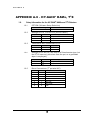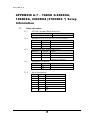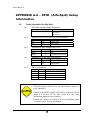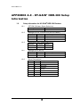
1
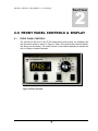
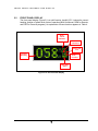
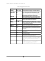
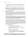
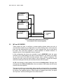
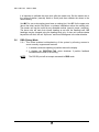
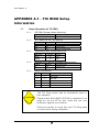
G R E E N H E R O N E N G I N E E R I N G LL C RT-20 DIGITAL ROTOR CONTROLLER USER GUIDE Document Revision 3.3 2006 Green Heron Engineering LLC 1107 Salt Road, Webster, NY 14580 Phone 585.217.9093 www.GreenHeronEngineering.com RADIO AND TELEVISION INTERFERENCE This equipment has been tested and found to comply with the limits for a Class B digital device, pursuant to Part 15 of the FCC rules. These limits are designed to provide reasonable protection against harmful interference in a residential installation. This equipment generates, uses and can radiate radio frequency energy and, if not installed and used in accordance with the instructions, may cause harmful interference to radio communications. However, there is no guarantee that interference will not occur in a particular installation. If this equipment does cause harmful interference to radio or television reception, which can be determined by turning the equipment off and on, the user is encouraged to try to correct the interference by one or more of the following measures: Reorient or relocate the receiving antenna. Increase the separation between the equipment and the receiver. Connect the equipment into an outlet on a circuit different from that to which the receiver is connected. Consult the dealer or an experienced radio/TV technician for help. You may also find helpful the following booklet, prepared by the FCC: "How to Identify and Resolve Radio-TV Interference Problems." This booklet is available from the U.S. Government Printing Office, Washington D.C. 20402. Changes and Modifications not expressly approved by the manufacturer or registrant of this equipment can void your authority to operate this equipment under Federal Communications Commissions rules. NOTICE The RT-20 may not be certified or recommended by some rotor manufacturers for use with their products. Use of this device may void the warranty of these devices and Green Heron Engineering LLC is not responsible for any damage, direct or incidental, that might occur through such use. Green Heron Engineering reserves the right to make changes for product improvement or manufacturing, without notice or any obligation to update units already sold. WARRANTY This product is warranted to be free of defects in materials and workmanship for 90 days. We will repair or replace, at our option, any equipment proven to be defective within the warranty period. All warranty work is F.O.B. Webster, NY, USA. This warranty is exclusive of abuse, misuse, accidental damage, acts of God or consequential damages, etc. Green Heron Engineering LLC liability shall not exceed the original purchase price of the equipment. TRADEMARKS M2 Orion is a trademark of M2 Antenna Systems, Inc. TIC RingRotor is a registered trademark of TIC General, Inc. Hy-Gain is a trademark of Hy-Gain Corporation Yaesu is a trademark of Yaesu/Vertex Standard USA All other products, company names, brand names, and trademarks are the property of their respective owners. This unit is normally supplied with a 3 amp 5x20 mm fuse in the rear panel fuse holder. If it is necessary, replace only with: 115 VAC – 3 amp max 230 VAC – 1.5 amp max TABLE OF CONTENTS 1.0 Introducing the RT-20 1 1.1 Special Terms Used 2 1.2 Prepare for RT-20 Hardware Configuration 3 1.3 RT-20 Hardware Configuration 3 1.4 Perform Setup 5 1.5 Connect the RT-20 to your Rotor 6 1.6 Configure the OFFSET Value 7 1.7 Calibrate Your System 7 2.0 FRONT PANEL CONTROLS & DISPLAY 9 2.1 FRONT PANEL CONTROLS 9 2.2 FRONT PANEL DISPLAY 12 3.0 SETUP MODE 14 3.1 SETTING THE OPTION PARAMETER 14 4.0 CALIBRATION 20 4.1 POT or HAM OPTIONS 20 4.2 CTR OPTION 21 5.0 OPERATING HINTS & ADVANCED 5.1 OPERATING HINTS 22 5.2 COMPUTER CONTROL OF RT-20 (EIA-232 Port) 23 5.3 CALIBRATION OF SIDEARM INSTALLATION 23 5.4 MASTER/SLAVE (M/S) MODE 24 5.5 M/C and S/C MODES 25 5.6 DBG (Debug) Mode 26 FEATURES 22 APPENDIX A.1 - TIC RING Setup Information 27 APPENDIX A.2 - ORION 2300 (Original) 28 APPENDIX A.3 - ORION 2800 (AC) 29 APPENDIX A.4 - ORION 2800 (DC) 30 APPENDIX A.5 - CREATE RC5 Series 31 APPENDIX A.6 - HY-GAIN® HAMx, T2X 32 APPENDIX A.7–YAESU G-800DXA, 1000DXA, 2800DXA(2700SDX *)Setup Information 33 APPENDIX A.8 – SPID (Alfa-Spid) Setup Information 34 APPENDIX A.9 - HY-GAIN® HDR-300 Setup Information 35 APPENDIX A.10 – ALLIANCE HD-73 Setup Information 36 APPENDIX A.11 – ROTOR DOCTOR RD-1800 Setup Information 36 APPENDIX B – Universal Rotor Setup Information (for Rotors not listed) 37 APPENDIX C – External Relay Control 41 APPENDIX D – DC Motor Fail-Safe 41 APPENDIX E – Chassis Schematic 41 APPENDIX F – Error Messages and Troubleshooting 41 R T – 2 0 Q U I C K S T A R T 1 Section G U I D E 1.0 Introducing the RT-20 The RT-20 Digital Rotor Controller represents a new concept in antenna aiming technology. Unlike conventional controllers, the RT-20 may be configured for use with virtually any communicationsgrade rotator, and it adds an array of features not found on any other controller today. At the heart of the RT-20 is an embedded microprocessor that allows for precise, repeatable commands that can be issued by turning a “point and shoot” heading knob, pressing the CW or CCW buttons, or by entering commands on a connected PC. With its flexibility and wide array of features, the RT-20 brings any rotator—old or new—into the digital age. Of particular interest to “multi-op” contesters and others with multiple arrays, two or more RT-20 Controllers may be linked together for complete control of all station antennas, even those on rotating towers. Side-mounted antennas may all be moved to the same heading simultaneously, or each antenna can maintain its own heading relative to the movement of the tower or other antennas. In the case of a rotating tower, antennas mounted on a RingRotor or a rotor atop the tower will compensate for tower movement by counter-rotating to accurately hold their position as the tower turns. Please Read This! Some users of electronic gear only read manuals when trouble occurs, or when seeking information about an unfamiliar feature or command. While the RT-20 is designed for very easy use and flexibility, the manual is an essential part of configuring the unit for use with your rotator. Take the time to read and follow the steps presented here, and you will soon be up and running with your RT-20. After installation, the manual should be retained for future reference. During the configuration steps, frequent reference is made to the Appendix sections at the back of this manual. These sections contain rotator-specific information needed to make the RT-20 work properly with your rotor. It will also be helpful to have the instruction manual for your rotator handy when determining voltage levels, AC or DC operation, cabling pinouts, etc. RT-20 manual updates, information on new firmware releases, application notes, and other product information may be found on our website at: www.GreenHeronEngineering.com. The website is especially useful when connecting the RT-20 to rotators that are not listed in this manual. Technical assistance can also be obtained using the contact information that appears on the inside front cover. 1 R T – 2 0 Q U I C K S T A R T G U I D E If your rotor does not have mechanical lim its, DO NOT attempt rotation other than with the CW and CCW pushbuttons before calibration has been completed and the sof t limits are pr oven to be working as desired. 1.1 Special Terms Used The following terms may be unfamiliar to new users of the RT-20 and are defined here for clarity. It is important to understand their meanings, as they will be used frequently during configuration and setup tasks: Endpoints— The counter-clockwise (CCW) and clockwise (CW) endpoints refer to the ends of rotation that would normally occur with a system that rotates exactly 360 degrees. Note that CCW and CW endpoint headings are the same, but at opposite ends of a 360degree arc (with the center-of-rotation being 180 degrees from either endpoint). Over-Travel— Rotation beyond the normal endpoints of 360 degrees. Point-and-shoot—This action refers to setting a direction with the front panel Heading Knob and allowing the RT-20 to execute this move automatically, stopping at the selected heading. Soft Limits—These are travel limits that can be programmed into the RT-20. The effect is similar to the mechanical limits built into many rotators, but it is achieved inside the controller and is fully programmable to allow over-travel (if supported by the rotor) or to reduce travel for installations requiring limiting the rotation to less than 360 degrees (a sidearm antenna mount, for example). If a rotator does not have mechanical endpoints, this feature helps avoid turning the rotor past a desired range. Ramp-up/Ramp-down—This RT-20 feature provides gradual startup and shutdown of rotor power to reduce stress on towers, antennas and rotors. This is achieved by pulsewidth-modulating the operating voltage for the rotor. Ramp-up is utilized for all starts, and ramp-down is used on all stops, except for MANUAL button presses. NOTE For the purpose of this manual, the terms “rotator” and “rotor” are used interchangeably. Also, the compass headings of 360 and 0 degrees are used interchangeably. 2 R T – 2 0 Q U I C K S T A R T G U I D E Setting up the RT-20 It is very important that you become familiar with the various options and settings described in this section of the manual before using your RT-20. Because of the flexibility of the unit, there are options that MUST be configured prior to hooking up and using it with your rotor IMPROPER CONNECTIONS OR SETTINGS COULD CAUSE PERMANENT DAMAGE TO YOUR CONTROLLER, ROTOR, OR BOTH. Green Heron Engineering will not be responsible for damage caused by improper settings or connections. 1.2 Prepare for RT-20 Hardware Configuration Refer to Appendix A of this manual and determine if your rotor type is listed there. This appendix describes settings and connections for most common rotor types. It is divided into subsections (A.1, A.2, A.3, etc.), with each section pertaining to a specific model. 1.2.1 If your rotor type is included in Appendix A, proceed directly to Step 1.3. Keep the appendix information at hand while configuring your unit. 1.2.2 If your rotator is not described in Appendix A refer to the Universal Setup Information contained in Appendix B. There, you will find a worksheet and tables to determine the proper settings for your controller unit. Use the completed worksheet and the other information in Appendix B to complete the tasks in Step 1.3. NOTE 1.3 Contact Green Heron Engineering or check out website for the latest information concerning your rotor. We have experience interfacing with virtually every rotor type in use! RT-20 Hardware Configuration Begin with these steps to configure the RT-20 for use with your rotator: 1. Ensure that the power cable is disconnected from the rear panel of the RT-20. 2. Remove the eight Phillips head screws securing the top cover and remove the cover. 3 R T – 2 0 Q U I C K S T A R T G U I D E 3. Familiarize yourself with main PC board as shown in Figure 1. Note the locations of all jumper plugs and wires identified with arrows. J12 J14 J6 J10 J5 J9 Transformer Figure 1. RT-20 PC Board Layout—Locations of Configuration Jumpers 4. Select your motor type (AC or DC) with J10, J12, and J14 as follows: Using the Appendix that applies to your rotor, set the jumpers to the positions listed in the table titled “Settings for J10, J12 and J14.” A pair of small needle nose pliers will be helpful when moving jumpers. 5. Select your transformer wire connections as follows: Only two transformer wires are used, regardless of the installation type. DO NOT connect unused transformer wires. Protect them from shorts by using the supplied wire nuts In the Appendix for your rotor, refer to the table titled “Transformer Wire Connections to J9” and connect two of the wires as indicated. Place the supplied wire nuts on the unused wires. 4 R T – 2 0 Q U I C K S T A R T G U I D E 5. Select Your Position Indicator Type: In the Appendix for your rotor, refer to the table titled “Settings for J5 and J6” and make the required jumper connections. 6. Reinstall the top cover of the RT-20, securing it with the screws removed earlier. The cover should be oriented so that there is a slight overhang at the top of the RT-20 front panel. 7. Verify that the 115/230 VAC switch on the rear panel is set properly. This switch MUST be set to the choice that is correct for the primary (mains) voltage that will power your RT-20. A small screwdriver may be used to move the switch, if necessary. If the position of the 115/230 VAC switch is moved, check the rear panel fuse for proper value. The fuse is an International Standard GMA 5mm x 20mm type, and should be a 3A fuse for 115 VAC operation, or a 1.5A fuse for 230 VAC operation. Replacement fuses are available at most electronics parts distributors. 8. Connect the power cord to the rear panel receptacle and set the front panel power switch to ON. You should see the software version number displayed briefly, followed by the operating display. This completes the hardware configuration of the RT-20. 1.4 Perform Setup This section explains how to set the correct OPTION parameter for your system. This ensures the correct startup conditions for your rotor, and makes items that pertain to your rotor accessible in the SETUP menu. For example, the BRAKE DELAY item is not available unless HAM is the selected OPTION. The correct OPTION for your rotator must be selected and saved prior to changing any other items in SETUP. Before making this selection, ensure that all hardware settings have been made as described in Section 1.3 above 1. Go into SETUP Mode as follows: Press and hold the SETUP/ITEM button until SETUP appears on the display. Choose the OPTION parameter by repeatedly pressing and releasing the SETUP/ITEM button until the display shows OPTION. 5 R T – 2 0 Q U I C K S T A R T G U I D E 2. Choose one of the operating options (POT, CTR or HAM) by rotating the heading knob until the correct operating option for your rotor is displayed: POT – 2 or 3-wire potentiometer or variable resistor CTR – Pulse Counter HAM – HAM-X or T2X Hy-Gain® Rotor with separate wedge brake control* 3. When the correct option for your rotator is displayed, save it as follows: Press the CHANGE button Press the SAVE button NOTE: 1.5 Rotors using a separate wedge-style brake are limited in accuracy for a number of reasons, including the fact that the brake sets in 6-degree increments. Also, these rotors have feedback potentiometers that can introduce significant “noise” into the system due to their mechanical design. It may take some time to get used to seeing these artifacts on the RT-20’s highly accurate digital display, even though additional filtering is done in software for these rotors. We also suppress the display of the tenths as superfluous for these types of rotors. Connect the RT-20 to your Rotor Remove power from rotor connec tions the unit before mak ing 1.5.1 Connect your rotator to the rear panel terminal strip of the RT-20 using the “Rotor Connections” table in the Appendix for your rotor. 1.5.2 If your rotor is not listed in Appendix A, use Appendix B (Universal Rotor Setup Information) along with the documentation for your rotor to determine the correct connections. Please contact Green Heron Engineering if you have any questions about connecting to your particular rotor. 6 R T – 2 0 1.6 Q U I C K S T A R T G U I D E Configure the OFFSET Value The offset value is the number of degrees that your counter-clockwise (CCW) endpoint is from true North. This might be a different value than your CCW mechanical stop if your rotor has wider rotation than 360 degrees. Offset can also be viewed as the desired center-of-rotation (180°) clockwise from North. For example: If your center-of-rotation were south, then your offset would be 0 (default) or if your center-of-rotation is North, then your offset would be 180 degrees. 1.6.1 Configure the proper Offset value by following the steps below: 1. Press and hold SETUP/ITEM until SETUP appears. 2. Press SETUP/ITEM until OFFSET appears. 3. Rotate the heading knob until the desired offset is displayed. Press the CHANGE button Press the SAVE button 1.7 Calibrate Your System 1.7.1 Refer to the Appendix for your rotor. If your operating OPTION was set to CTR (Pulse Counter), set the value as follows: 1. Enter the divide ratio (number of pulses in a 360-degree rotation) for your rotor as follows: • • • Press and hold down the SETUP/ITEM button until SETUP appears in the display window. Repeatedly press SETUP/ITEM until DIVIDE HI appears on the display. o Select the two high-order digits by rotating the heading knob. (Example: For 1785 pulses, “17” would be the high-order digits.) o Press the CHANGE button. Repeatedly press SETUP/ITEM until DIVIDE LO appears on the display. o Select the 2 low-order digits by rotating the heading knob. (Example: For 1785 pulses, “85” would be the low-order digits.) o Press the SAVE button. 2. Calibrate to the actual (physical) heading of your antenna. • • Note the current heading of your antenna using a compass. Press and hold down the SETUP/ITEM button until SETUP appears in the display window. 7 R T – 2 0 Q U I C K S T A R T o o o G U I D E Repeatedly press SETUP/ITEM until CALIBRATE appears on the display. Rotate the heading knob until the display indicates the current heading of your antenna. Press the CHANGE button, followed by the SAVE button. 1.7.2 If your operating OPTION was set to POT or HAM, proceed as follows: DO NOT use the Point-and-Shoot knob before your rotor is fully calibrated. Rotors without mechanical limits may be damaged or rotor loops may be exceeded if unintended over-travel occurs. If your rotor does not have mechanical stops at 360 degrees of rotation, insure that you or a helper is positioned to watch antenna travel during calibration 1. Using the CCW button on the front panel, turn your rotor until the CCW endpoint is reached. • If your rotor has mechanical stops at 360 degrees, simply turn it until it stops. Otherwise, turn the rotor only as far as 180 degrees CCW from the desired center-of-rotation.) 2. Press CANCEL and CCW simultaneously until CAL CCW appears on the display. 3. Using the CW button on the front panel, turn your rotor 360 degrees clockwise from the previous setting until your antenna is back to exactly the same heading as before. (Or against the CW stop if your stops are 360 degrees apart.) 4. Press CANCEL and CW simultaneously until CAL CW is displayed. completes the calibration. 8 This F R O N T P A N E L C O N T R O L S & D I S P L A Y 2 Section 2.0 FRONT PANEL CONTROLS & DISPLAY 2.1 FRONT PANEL CONTROLS The controls on the front of the RT-20 include three push buttons, the heading knob and the power switch as shown in Figure 2. Each of the push buttons has two labels, one above and one below. The active function of the buttons depends on whether the unit is in Setup or Normal Operation. Figure 2. RT-20 Front Panel 9 F R O N T P A N E L C O N T R O L S A N D D I S P L A Y 2.1.1 Front Panel Buttons—Normal Operation When the RT-20 is in normal operation, the push buttons function using the labels above the buttons. Table 1 summarizes their functions. Table 1. Button Functions in Normal Operation Button Label CCW CW CANCEL Button Function Turns rotor counter-clockwise Turns rotor clockwise In normal operation mode CANCEL can be used in three ways: • A click of the CANCEL button cancels the current rotation event from the front panel heading knob or external RS-232 line. • Holding the CANCEL button down for 2 seconds places the unit into SETUP. • A click of the CANCEL button toggles in or out of M/C, M/S, or S/C mode to allow a manual operation to be performed. 2.1.2 Heading Knob—Normal Operation The heading knob on the RT-20 is used to choose a heading for “Preset/Pointand-Shoot” rotation. The scale is appropriate for either a North or South centerof-rotation. When the knob is moved to the desired heading, the RT-20 begins rotor movement automatically. NOTE: The scale is a close approximation of the knob position. The exact position is always shown on the front panel digital display. 2.1.3 Front Panel Buttons—Setup Operation When the RT-20 is in Setup, the three push buttons function using the labels below the buttons. Table 2 summarizes their functions. Table 2. Button Functions in Setup Button Label Button Function SETUP/ITEM The SETUP/ITEM button has two functions. • Initiate Setup Mode: Press and hold down the button for 2 seconds, release when “SETUP” appears in the display window. • Select the next item in the SETUP menu: Repeatedly press the button until the desired setup item appears on the display. Modify the currently selected item to the value shown in the display window as set by the heading knob. CHANGE SAVE Save changes and exit setup mode 10 F R O N T P A N E L C O N T R O L S A N D D I S P L A Y 2.1.4 Heading Knob—Setup Operation When in SETUP, the Heading Knob is used to select desired values on the display. 2.1.5 Combined Button Functions Additional functions are available when certain combinations of buttons are pushed together. Refer to Table 3 for an explanation of these additional functions. When invoking these functions, lead with the CANCEL slightly ahead of the CW, CCW or both. Table 3. Combined Button Functions Button Combination Function CANCEL+CCW CANCEL+CW CANCEL+CCW+CW Calibrate CCW at CCW endpoint. Calibrate CW at CW endpoint. Restores all default values to factory settings except for the OPTION parameter. 11 F R O N T 2.2 P A N E L C O N T R O L S A N D D I S P L A Y FRONT PANEL DISPLAY The front panel display (Figure 3) is a multi-function, backlit LCD. It shows the current heading, position of preset knob, state of operation (MAN for Manual, REM for Remote, and PRE for Preset-in-progress). An explanation of these functions appears in Table 4. OverTravel Indicator Direction Indicators Soft Limit Ind. Current Heading Knob Position Operating State Figure 3. RT-20 Front Panel Display 12 F R O N T P A N E L C O N T R O L S A N D D I S P L A Y Table 4. Display Fields and Functions Field Name Current Heading Over-Travel Indicator Soft Limit Direction Indicators Valid Values 000.0 – 360.0 OT BRK < > Definition Compass heading of antenna in a properly calibrated system. (Tenths not displayed for OPTION HAM.) Over-Travel outside of the normal endpoints of 360degree rotation. (Rotors that allow rotation beyond 360 degrees with wider stops, or no stops at all use this.) Brake Activated (HAM X style electrical brake) Rotor has reached the soft limit set in the rotor SETUP. The RT-20 will not allow rotation beyond these points. Direction of current Rotation/Movement. Right indicates clockwise; left indicates counter-clockwise. Knob Position 0 – 359 Operating State MAN Manual—Local operation with front panel controls. PRE Preset—Displayed when RT-20 has sensed movement of the heading knob and a point-and-shoot operation is in progress. REM Remote—Unit being controlled via the RS-232 line from another device. M/S Master/Slave Mode—Unit connected to other RT-20 for coordinated operation. M/C Master Counter-Rotate—Connected mode S/C unit can compensate for movement from this unit. S/C Slave Counter-Rotate—Slave unit is compensating for movement from mode M/C unit, such as on a rotating tower, where a specific antenna must maintain its heading. DBG Debug—Used for system troubleshooting. Provides continuous display update, and disables motor shutdown. No position feedback is present. Shows exact position of the heading knob. It is used for choosing a precise setting when doing setup commands or in “point-and-shoot” operation. 13 S E T U P 3 Section M O D E 3.0 SETUP MODE The RT-20 rotor controller allows you to program virtually every aspect of your rotor’s operation. The controller’s SETUP menu is used to set all operating parameters. The first setup task is to select the OPTION parameter. This prepares the controller for the requirements of your rotor system. The correct OPTION for your rotator must be selected and saved prior to changing any other items in SETUP 3.1 SETTING THE OPTION PARAMETER The OPTION parameter setting provides the correct startup conditions for your system and makes items that pertain to your rotor accessible in the SETUP menu. For example, the BRAKE DELAY item is not available unless HAM is the selected OPTION. The RT-20 supports three different OPTION values: POT, CTR and HAM. 3.1.1 POT 2 or 3-wire potentiometer or variable resistor. The POT option uses the potentiometer method of determining the position of the rotor. The RT-20 reads the voltage on the wiper of the potentiometer using a precision A/D converter and displays the result in degrees. 3.1.2 CTR Pulse Counter The CTR option uses the “pulse counter” method of determining the position of the rotor. A reed or proximity switch generates pulses, which are read and counted by the RT-20. This count is used to calculate the current position of the rotator in degrees. 14 S E T U P M O D E 3.1.3 HAM – HAM-X or T 2 X Hy-Gain ® Rotor with separate wedge brake control. The HAM option uses the potentiometer method of determining the position of the rotor. In addition it controls a separate wedge brake included in these rotors. When the HAM option is selected, the RT-20 waits 300 milliseconds (ms) after disengaging the brake before starting the motor. It also delays setting the brake after rotation is complete. The user may adjust the brake delay from 0 to 5.9 seconds. The RT-20 uses half the potentiometer in these rotors because the wiper is grounded. The software smoothes out the readings during A/D conversion for HAM-style rotors. 3.1.4 To setup the OPTION parameter, perform the following steps: 1. Enter SETUP mode • • Press and hold down the SETUP/ITEM button for 2 seconds Release the SETUP/ITEM button when SETUP appears on the display. 2. Choose the OPTION parameter • Repeatedly press and release the SETUP ITEM button until SETUPOPTION = is displayed o The currently set option will be displayed after the equals sign (=). o The bottom line on the display will indicate NEW = XXX. 3. Set the OPTION parameter for your rotor • • • Rotate the heading knob until the desired OPTION (POT, CTR or HAM) is displayed after NEW = on the display. Press the CHANGE button when the correct OPTION for your rotator is displayed. Press the SAVE button to save the option and exit the SETUP menu. 15 S E T U P M O D E 3.1.5 SETTING OTHER PARAMETERS This same sequence that was used to set up the OPTION parameter is used to modify any setup parameter (SELECT, CHANGE, SAVE). It is important to remember that if you change an OPTION parameter, you must SAVE and reenter the SETUP menu to make any other changes TIP: Some menu items can change calculations and affect related options, so it’s a good idea to only change one item at a time until you become familiar with the RT-20. For example, changing the CTR divide ratios will change the CALIBRATE, the OFFSET will change the SOFT LIMITS to match, etc. 3.1.6 SETUP ITEMS This section provides a detailed description of the options available in the SETUP menu. The parentheses indicate the option setting(s) under which the item is available. CALIBRATE (CTR) – This item calibrates the directional display to the physical direction of your antenna. OFFSET (CTR, POT, HAM) – Sets the CCW endpoint for your system in degrees clockwise from true North. The default setting is “0”. This means that the default stops are at North with a South center-of-travel. To set a North center, you would set the OFFSET to 180. This setting also affects the soft limits within the RT-20 and repositions them automatically if you change the OFFSET value. • • • You may have both “South center” and “North center” antennas on the same mast and rotor. For example, you may wish to put a VHF antenna on South center and HF antenna on North center. You can select which center-of-rotation is to be used by simply changing the OFFSET. The OFFSET is also useful in a POT system to compensate for mast slippage as a temporary measure until you can re-align correctly. Mobile “rover” stations can use the OFFSET feature as well. Simply enter the amount of offset depending on how far off your vehicle is parked from a North heading. REV DELAY (CTR, POT, HAM) – This sets the delay enforced by the RT-20 before allowing a reversal in motor direction. This is done to reduce tower stresses, and the delay is adjustable in 100 ms increments up to a maximum of 5.9 seconds (59 on the display). 16 S E T U P M O D E BRK DELAY (HAM) – This sets the delay for brake application, after rotation, of a HAM-style rotor that employs a separate wedge brake. The delay is adjustable and displayed in 100 ms increments up to a maximum of 5.9 seconds (59 on the display). SPEED (CTR, POT, HAM) – This selects the motor speed, 1 to 11 where 1 is 10%…10 is 100%. For speeds within 1 to 10, ramp-up and ramp-down power is applied to the rotator, whether using point-and-shoot or external control. This reduces tower stress on large arrays. Speed 11 is full speed with no ramp-up or ramp-down conditioning. CCW LIMIT (CTR, POT, HAM) – Selects the absolute heading for the CCW soft limit. The soft limit may be set +/- 180 degrees from the normal CCW endpoint. (Normal endpoints apply to systems that allow 360 degrees of rotation with mechanical stops.) CW LIMIT (CTR, POT, HAM) – Selects the absolute heading for the CW soft limit. The soft limit may be set +/- 180 degrees from the normal CW endpoint. (Normal endpoints apply to systems that allow 360 degrees of rotation with mechanical stops.) OPTION (CTR, POT, HAM) – Selects the rotor type. Described earlier in this section. DIV HIGH (CTR) – Selects the first two digits (high order) of the pulse divider. The divider number is equal to the number of pulses in a 360-degree rotation. Thus if your rotor provides 1785 pulses in 360 degrees, the DIV HIGH value is set to 17. DIV LOW (CTR) – Selects the last two digits (low order) of the pulse divider. The divider number is equal to the number of pulses in a 360-degree rotation. Thus if your rotor provides 1785 pulses in 360 degrees, the DIV LOW value is set to 85. (Always set the DIV HIGH first, then the DIV LOW.) CAL RANGE (POT, HAM) – This is the degree range that the potentiometer calibrate routines will assume for the distance traveled between the CCW and CW calibration points. This value defaults to 360 degrees and should not be changed unless you cannot rotate your antenna full 360 degrees in order to perform the potentiometer calibration. (A sidearm application on a tower may be one example of this.) You can calibrate the rotor prior to physical installation, or use the CAL RANGE to set this parameter. Refer to Section 5—Advanced Features—for a detailed sidearm calibration procedure. 17 S E T U P M O D E MODE (CTR, POT, HAM) – Selects the operating mode of the RT-20 controller. • • NRM Mode – NORMAL mode allows manual control, point-and-shoot and computer control via the rear panel EIA-232 port. M/S Mode–Master/Slave Mode, where multiple RT-20 controllers are linked together. o Usage and Examples: Master/Slave mode allows one RT-20 to control other RT-20 controllers via the EIA-232 port. This allows movement of multiple rotors and antennas to the same heading without having to set each one individually. The M/S MODE is intended for use in controlling stacks of HF monobanders or tribanders that are on different rotors (or even different rotor types). It allows the operator to turn the entire stack together or quickly separate them for individual rotation. When you set the MODE to M/S, you may quickly disable or enable the M/S mode by pressing the CANCEL button. o Functionality If you only have a stack of two antennas, each with its own rotor, either controller may be used to turn the pair. If you have three or more antennas on different rotors, then one of the controllers must be designated as the Master. The controller designated as the Master is the only one that will turn all of the antennas. The other controllers will only turn the antennas they are directly connected to. Refer to Section 5—Advanced Features—for more detail on M/S operation and EIA-232 connections. • M/C – “Master/Counter-Rotate” Mode o Usage and Examples Master/Counter-Rotate Mode is used for the bottom rotor (or tower) in a system where two rotors are used in series along the same “mast”. Examples of this are a rotor at the top of a rotating tower, or two rotating joints on the same structure (or rotating rings mounted on a rotating tower). o Functionality M/C mode sends the heading data to other RT-20s that control the upper rotor so that it may calculate the heading for the antennas above. 18 S E T U P M O D E • S/C – Slave/Counter-Rotate Mode o Usage and Examples S/C mode is used for the slave rotor(s) as described in M/C. It reads the data from the M/C unit and maintains the heading for the upper antennas while the bottom is moving. The S/C controller in a properly implemented system allows complete independent operation of the slave antennas from the ones fixed to the rotating tower. 19 4 Section C A L I B R A T I O N 4.0 CALIBRATION Use the CCW and CW buttons to turn your antennas during calibration steps. DO NOT use the Point-and-Shoot knob before your rotor is fully calibrated. Rotors without mechanical limits may be damaged or rotor loops may be exceeded if unintended over-travel occurs. You either do 4.1 OR 4.2 depending on your rotor OPT ION t ype. 4.1 POT or HAM OPTIONS ONLY It is recommended to begin with the default calibration settings in the controller. You can restore these if necessary with the RESTORE EE PROM command, (CANCEL + CCW + CW buttons). Always use the RESTORE EE PROM command when connecting the RT-20 to a new rotor type. 4.1.1 Perform the following steps to properly calibrate the RT-20 1. Use the CCW button to turn the rotor in order to define the normal (nonover-travel) CCW limit. • • If your rotor has 360-degree stops, turn the rotor CCW to the mechanical stop. If your rotor DOES NOT have 360-degree stops o If the OFFSET is at 0, turn CCW to visual due north. o If the OFFSET is at 180. turn CCW to visual due South. 2. Press CANCEL and CCW simultaneously and hold until CCW CAL is displayed. This sets the CCW Endpoint 20 C A L I B R A T I O N 3. Use the CW button to turn the rotor in order to define the normal (non-overtravel) CW limit. • • If your rotor has 360-degree stops, turn the rotor CW to the mechanical stop. If your rotor DOES NOT have 360-degree stops o Use the CW button to turn the rotor exactly 360 degrees until the antennas are positioned back in the same visual direction as in Step 1 above. This is the CW endpoint. 4. Press CANCEL and CW simultaneously and hold until CW CAL is displayed. The numbers displayed are the results of the analog-to-digital (A/D) conversion of the voltage read on the potentiometer. They will vary depending on the amount of travel the indicator potentiometer actually moves, but the CCW value should be fairly low and the CW value should be significantly higher. The larger the difference between the two numbers, the higher the resolution of the heading display will be. A system that only uses 2 turns of a 10- turn pot will not have nearly the resolution of one that uses 8 or 9 turns of the same pot. The accuracy and resolution of the RT-20 controller depends entirely on the amount of change of this A/D reading and the linearity of the potentiometer used. The maximum resolution is about 1/3 degree with this option. 4.2 CTR OPTION ONLY Ensure that the correct divider value is set with DIV HI and DIV LOW based on the number of pulses in a 360-degree rotation. Simply turn your antenna to a known direction visually, and then set the OFFSET value to yield the desired end or center-of-rotation headings. Finally, set the CALIBRATE value to the same heading as the antennas are physically pointed. NOTE: The RT-20 cannot adjust the actual position of your antenna in relation to the physical endstops OR in relation to your coax rotor loops as installed. 21 A D V A N C E D 5 Section F E A T U R E S 5.0 OPERATING HINTS & ADVANCED FEATURES 5.1 OPERATING HINTS A review of the Operating Hints below will help you get the most out of your RT-20 and resolve minor difficulties that may be encountered. In addition, Green Heron Engineering is available to assist with any questions you may have about your controller. Use the contact information at the front of this manual to reach us. 1. The voltage taps listed in the configuration charts (Appendix A) are normal settings for short-to-moderate cable runs. If you find that your rotor turns more slowly than usual, or the ramp-down function does not operate correctly, try using the next higher voltage tap on the transformer (i.e., use red wire instead of orange). 2. Some rotors work better under pulse width-modulated (PWM) speed control than others. In general, DC motors appear to operate better than AC motors in this regard. Also, lightly-loaded rotors and heavily-loaded rotors behave differently as they are ramped down. Experimentation may be needed with the speed control and voltage setting to optimize your system. 3. When evaluated with the RT-20, HAMx and T2X rotors exhibited the least effective speed control. For these rotors, we recommend setting the RT-20 to SPEED= 11 to eliminate the PWM control. 4. We recommend that the RT-20 soft limits be set to values that will prevent your rotor from turning into (or possibly through) its mechanical limits. Setting the soft limits to 5 degrees “early” is a good practice and will help avoid this problem. 5. Rotors without mechanical limits must depend entirely on the controller to prevent rotation beyond the desired range and to prevent damage to your coax and/or potentiometer. We strongly recommend you use the FAIL-SAFE option in Appendix D for TIC RingRotors and Alfa-Spids as there rotors do not have limit switches. 22 A D V A N C E D F E A T U R E S 6. Your RT-20 comes from the factory set up for a 36 VDC motor (mid-voltage) and a potentiometer-positioning indicator system. The offset value is zero, which needs a CCW & CW endpoint of North, and a South center-of-rotation. You can return to these default settings at any time by pressing the CANCEL, CW, and CCW buttons at the same time and holding until the unit resets. 7. The RT-20 is protected by a fuse on the rear panel. If the controller shows no sign of power, the fuse may be blown. The fuse is an International Standard GMA 5mm x 20mm type, and should be replaced with a 3A fuse for 115 VAC operation, or a 1.5A fuse for 230 VAC operation. Replacement fuses are available at most electronics parts distributors. 5.2 COMPUTER CONTROL OF RT-20 (EIA-232 Port) The RT-20 is equipped with a fully operational RS-232 port. This port can be used for simple computer “read and control” or in combination with other RT-20 controllers in order to implement Master/Slave or Master/Counter-Rotation control of antenna arrays. The protocol implemented in the RT-20 is based on the Hy-Gain® DCU-1 protocol. It reports headings and turns to headings with the same commands implemented in DCU-1. Set your software to use DCU-1 protocol and the RT-20 should work fine with it. Additional commands are provided for the advanced features that only your RT-20 can perform. 5.3 CALIBRATION OF SIDEARM INSTALLATION If your rotor uses a CTR position type indicator, sidearm calibration is easy. Simply calibrate as specified earlier, and set the soft limits to ensure that your antenna does not turn far enough to hit the tower. If your rotor uses a POT or is a HAM type indicator, the calibration is slightly more involved, as the antenna cannot be turned through a complete 360 degrees in order to set the A/D values. Although it can be done while maintaining OFFSET at a nominal 0 or 180 degrees, we suggest you start with the method below: 1. Using SETUP menu, change the value of CAL RANGE to 180. (Allowable options are 90, 180, 270, and 360.) 2. Turn the rotor CCW to the most CCW heading you want to allow, keeping in mind that the antenna must not be allowed to strike the tower. 3. Perform the CCW Calibration by pressing the CANCEL + CCW buttons. 4. Turn the antenna CW until it is visually 180 degrees from the position noted in Step 2 (or to CAL RANGE setting). Perform the CW Calibration by pressing the CANCEL + CW buttons. 23 A D V A N C E D F E A T U R E S 5. Turn the antenna to a known heading visually and subtract this “real” heading from the indicated heading on the display. Set the OFFSET value to this difference. 6. Set the soft limits to values that prevent the antenna from striking the tower. NOTE: For new installations you could calibrate before you mount the antenna, or calibrate the rotor on the ground, then mechanically set the antenna to match a 0 or 180 degree OFFSET. In any event, you must make sure the mechanical stops of the rotor are outside the intended range of rotation. 5.4 MASTER/SLAVE (M/S) MODE M/S mode allows multiple antennas to be rotated as if they were on the same mast, even if in fact they are on separate towers, masts or rotor types. Primarily intended for stacked arrays of similar antennas, this mode could be useful in other ways. One might be the VHF operator with antennas for different bands on different rotors or towers. You could turn the SHF array to a desired heading as you work a distant station on the lower bands on a different tower. A controller in the M/S mode sends commands to other controllers using the EIA-232 port. Controllers in NRM mode or M/S mode will “read” these commands and turn their motors to match. If you wish to momentarily disable the commands from being sent from the M/S unit, simply press the CANCEL button and the MODE will change to MAN on the display. Pressing CANCEL again will return to M/S mode. An M/S unit will send commands for point-and-shoot and computer-generated events, but not for manual button presses. If you have only two controllers, both units may be set to M/S and then either one will turn the stack, unless momentarily disabled with CANCEL. With three or more rotors in the stack, only one unit may be designated as M/S because of the interconnection scheme. In addition, computer control may still be used on the stack. The computer must be connected to the unit that will be the M/S mode unit, if a computer is used with a two-unit setup, then only one RT-20 (the one connected to the computer) can be the Master unit. 5.4.1 INTERCONNECTIONS: 1. For two controllers without a computer interface • • Connect the two units together with a DB-9 null modem cable. The only pins needed are 2-3, 3-2, and 5-5. 2. For connection with a computer and two or more RT-20 units, proceed as follows: • • • Cable the units as shown in Figure 4. All connectors are assumed to be DB-9 type. Note that only two wires are needed on units set to MODE NRM. • Pre-made cables are available from Green Heron Engineering. Check our website for details. 24 A D V A N C E D F E A T U R E S RT-20 MODE NRM (S/C) 33 22 55 RT-20 MODE NRM (S/C) 33 22 55 RT-20 MODE M/S (M/C) 33 33 22 22 Com 55 55 Computer Figure 4. Master/Slave (M/S) Interconnect Example (For multiple RT-20s connected together) 5.5 M/C and S/C MODES These modes are used to configure a counter-rotating scheme where one rotor is mounted above another as you might wish to do with a rotating tower. In this case, the tower turns the antennas that are fixed to it, and a separate rotor turns a mast above the tower. This could allow separate or slaved operation of stacked antennas, or separate control of two independent antenna systems. In this configuration, the lower rotor controller is set to MODE M/C while the upper controller is set to S/C (Master and Slave Counter-Rotation). The cabling is the same as you would use for the M/S two-rotator scheme, with or without a computer. The computer can only control the lower rotator in this configuration. The S/C unit always seeks the heading set with the point-and-shoot knob on the front panel. All S/C units attempt to hold headings as set with the Heading Knob. Although units will respond to the CW and CCW buttons, the next rotation of the master unit will cause a return to the knob position. The lower unit will turn as commanded, either manually, point-and-shoot, or by software command, and the upper unit will compensate and hold the desired, indicated heading by turning in the opposite direction. When beyond an endpoint (soft limits), the upper unit “flops over” and turns 360 degrees in the other direction. 25 A D V A N C E D F E A T U R E S It is important to calibrate the slave units after the master one. Set the master one to the center-of-rotation (normally North or South) and then calibrate the slaves to the same heading. Use M/C for your main rotating tower base or rotating joint. Use S/C for the upper rotor (above the tower) and/or Ring Rotor or sidearm installations above the rotating joint. The master unit may be turned by any allowable method (manual, preset, computer). The slave units will track their current heading as set with the heading knob. S/C headings may be changed using the heading knob only. A slave unit counter-rotates beyond the soft limit, the unit “flops over” and turns 360 degrees in the other direction. 5.6 DBG (Debug) Mode 5.6.1 This mode enables troubleshooting of the system by allowing access to some normally-suppressed features: 1. It enables continuous updating of position data on the display. 2. It disables the POSITION FAIL motor shutdown if position feedback indicates that the rotor is not moving. NOTE: The RS-232 port will not accept commands in DBG mode. 26 A P P E N D I X A APPENDIX A.1 - TIC RING Setup Infor mation 1.1. Setup Information for TIC RING 1.1.1 OPTION (Software Setup Selection) Rotor TIC RING Rotor 1.1.2 SETTINGS for J10, J12 and J14 Jumper J10 J12 J14 1.1.3 SETUP OPTION POT Position 2-3 2-3 2-3 Transformer Wire Connections to J9 Wire Color Brown Connect to Orange 1.1.4 to Jumper J9-3 J9-4 Settings for J5 and J6 (Standard Potentiometer) Jumper J5 J6 1.1.5 Connection type Jumper short Jumper short Screw connector short Position 1-2 1-2 Connection type Jumper short Jumper short Rotor Connections TIC RT-20 Description 2 3 1 2 MOT CCW MOT CW 4 5 CW/REF 5 4 WIP/POS 6 3 CCW/GND The TIC Ring rotator has no mechanical stops or limit s witches. Please install FAIL-SAFE OPTION in Appendix D on page 43 as the RT-20 sof t limits ar e the only protection against over-rotation. Please be careful to nsure that your TIC Ring does not over-travel during calibration. 27 A P P E N S I X A APPENDIX A.2 - ORION 2300 (Original) 1.2. Setup Information for the Orion 2300 1.2.1 1.2.2 OPTION (Software Setup Selection) Rotor SETUP OPTION Orion 2300 (Original) rotor POT SETTINGS for J10, J12 and J14 (36 VAC Motor) Jumper J10 J12 J14 1.2.3 Position 1-2 1-2 1-2 Transformer Wire Connections to J9 Wire Color 1.2.4 Connect Jumper Brown to J9-1 Red or Vio to J9-2 Settings for J5 and J6 (Standard Potentiometer) Jumper J5 J6 1.2.5 Connection type Jumper short Jumper short Screw connector short Position 1-2 1-2 Connection type Jumper short Jumper short Rotor Connections (Note that Terminal 3 gets two wires) OR-2300 RT-20 Description 1 3 MOT GND 2 2 MOT CCW 3 4 1 5 MOT CW POT REF 5 4 POSITION 6 3 GROUND 28 A P P E N S I X A APPENDIX A.3 - ORION 2800 (AC) 1.3. Setup Information for the Orion 2800 AC 1.3.1 1.3.2 OPTION (Software Setup Selection) Rotor SETUP OPTION Orion 2800 AC rotor CTR DIV HIGH=39 DIV LOW=60 SETTINGS for J10, J12 and J14 (36 VAC Motor) Jumper J10 J12 J14 1.3.3 1.3.4 NOTE: Connection type Jumper short Jumper short Screw connector short Transformer Wire Connections to J9 Wire Color Connect Brown Red or Vio to to Jumper J9-1 J9-2 Settings for J5 and J6 (Pulse Counter) Jumper J5 J6 1.3.5 Position 1-2 1-2 1-2 Position 2-3 2-3 Connection type Jumper short Jumper short Rotor Connections OR-2800 AC RT-20 Description 1 3 MOT GND 2 3 2 1 MOT CCW MOT CW 5 4 POS 6 3 GND The ORION 2800 AC supports +/- 14 degree over-travel. The RT20’s soft limits may be set to match if desired. 29 A P P E N S I X A APPENDIX A.4 - ORION 2800 (DC) 1.4. Setup Information for the Orion 2800 DC 1.4.1 1.4.2 1.4.3 OPTION (Software Setup Selection) Rotor SETUP OPTION Orion 2800 DC rotor CTR DIV HIGH=39 DIV LOW=60 Pulse Counter Hi/LO Settings Rotor Xxx Orion 2800 DC rotor DIV HIGH Value 39 Orion 2800 DC rotor DIV LOW 60 (3960) SETTINGS for J10, J12 and J14 (42 VDC Motor) Jumper J10 J12 J14 1.4.4 Position 2-3 2-3 2-3 Transformer Wire Connections to J9 Wire Color Brown Connect to Red/Vio 1.4.5 NOTE: to Jumper J9-3 J9-4 Settings for J5 and J6 (Pulse Counter) Jumper J5 J6 1.4.6 Connection type Jumper short Jumper short Screw connector short Position 2-3 2-3 Connection type Jumper short Jumper short Rotor Connections OR-2800 DC RT-20 Description 1 1 MOT CW 2 5 2 4 MOT CCW POS 6 3 GND The ORION 2800 DC supports +/- 14 degree over-travel. The RT20’s soft limits may be set to match if desired. 30 A P P E N S I X A APPENDIX A.5 - CREATE RC5 Series 1.5. Setup Information for the Create RC5 Series Rotators 1.5.1 1.5.2 OPTION (Software Setup Selection) Rotor SETUP OPTION Create RC5 Series POT Settings for J10, J12 and J14 (28 VAC Motor) Jumper J10 J12 J14 1.5.3 Position 1-2 1-2 1-2 Transformer Wire Connections to J9 Wire Color 1.5.4 Connect to J9-1 Orange to J9-2 Settings for J5 and J6 (Standard Potentiometer) Position 1-2 1-2 Connection type Jumper short Jumper short Rotor Connections (Terminal 3 gets 2 wires) RC5 NOTE: Jumper Brown Jumper J5 J6 1.5.5 Connection type Jumper short Jumper short Screw connector short RT-20 Description 1 3 MOT RET/GND 2 1 MOT CW 3 4 2 5 MOT CCW POT REF 5 4 POS 6 3 GND The Create RC5 Series allows moderate over-travel and supports wider soft limits. 31 A P P E N S I X A APPENDIX A.6 - HY-GAIN ® HAMx, T 2 X 1.6. Setup Information for the HY-GAIN® HAMx and T2X Rotators 1.6.1 OPTION (Software Setup Selection) Rotor SETUP OPTION 2 HY-GAIN® HAMx and T X 1.6.2 Settings for J10, J12 and J14 (34 VAC Motor) Jumper J10 J12 J14 1.6.3 1.6.4 Position 1-2 1-2 1-2 Connection type Jumper short Jumper short Screw connector short Transformer Wire Connections to J9 Wire Color Connect Brown Red or Vio to to Jumper J9-1 J9-2 Settings for J5 and J6 (This rotor is a Potentiometer type, but the RT-20 uses only two wires from the pot, as a grounded wiper is employed.) Jumper J5 J6 1.6.5 HAM Position 1-2 2-3 Connection type Jumper short Jumper short Rotor Connections (3 rd pot wire N/C) HAMx RT-20 1 3 Description MOT RET/GND 2 3 6 4 BRK POS 4 7 CAP 5 6 1 2 MOT CW MOT CCW 8 8 CAP 32 A P P E N S I X A APPENDIX A.7 – YAESU G-800DXA, 1000DXA, 2800DXA (2700SDX *) Setup Infor mation 1.7. Setup Information 1.7.1 1.7.2 OPTION (Software Setup Selection) Rotor SETUP OPTION Yaesu types referenced above POT Settings for J10, J12 and J14 (42 VDC Motor) Jumper J10 J12 J14 1.7.3 Position 2-3 2-3 2-3 Transformer Wire Connections to J9 Wire Color 1.7.4 1.7.5 Connection type Jumper short Jumper short Screw connector short Connect Jumper Brown to J9-3 Yellow to J9-4 (24 VDC) for 2700SDX* Orange to J9-4 (36 VDC) for G-800DXA, 1000DXA and 2800DXA Settings for J5 and J6 Jumper J5 1-2 Position Connection type Jumper short J6 1-2 Jumper short Rotor Connections Yaesu RT-20 Description 1 5 POT REF. 2 3 4 3 POS GROUND 4 2 MOT CCW 5 1 MOT CW 6 4 N/C 7 3 N/C 33 A P P E N S I X A APPENDIX A.8 – SPID (Alfa-Spid) Setup Infor mation 1.8. Setup Information for Alfa-Spid 1.8.1 OPTION (Software Setup Selection) Rotor Alfa-Sid 1.8.2 CTR DIV HIGH=3 DIV LOW=60 Settings for J10, J12 and J14 (24 VDC Motor) Jumper J10 J12 J14 1.8.3 SETUP OPTION Position 2-3 2-3 2-3 Transformer Wire Connections to J9 Wire Color Brown Connect to Yellow 1.8.4 1.8.5 Connection type Jumper short Jumper short Screw connector short to Jumper J9-3 J9-4 Short runs (24 VDC) Settings for J5 and J6 Pulse Counter Jumper J5 2-3 Position Connection type Jumper short J6 2-3 Jumper short Rotor Connections SPID 1 RT-20 1 Description MOT CW 2 2 MOT CCW 3 3 GROUND 4 4 POS The Alf a-Spid rotator has no mechanical stops or limit s witches. Please install FAIL-SAFE OPTION in Appendix D on page 43 as the RT-20 sof t limits ar e the only protection against over-rotation. Please be caref ul to ensure that your Alfa-Spid does not over-travel during calibration. 34 A P P E N S I X A APPENDIX A.9 - HY-GAIN ® HDR-300 Setup Infor mation 1.9. Setup Information for HY-GAIN® HDR-300 Rotators 1.9.1 OPTION (Software Setup Selection) Rotor HY-GAIN® HDR-300 1.9.2 Position 1-2 1-2 1-2 Connect to Orange 1.9.5 Connection type Jumper short Jumper short Screw connector short Transformer Wire Connections to J9 Wire Color Brown 1.9.4 HAM Settings for J10, J12 and J14 (24 VAC Motor) Jumper J10 J12 J14 1.9.3 SETUP OPTION to Jumper J9-1 J9-2 Settings for J5 and J6 Jumper J5 Position 1-2 Connection type Jumper short J6 1-2 Jumper short Rotor Connections HAMx 1 RT-20 1 Description MOT CW 2 2 MOT CCW 3 4 3 6 GROUND BRAKE 8 5 POT REF 9 4 POS 10 3 GND 35 A P P E N S I X A APPENDIX A.10 – ALLIANCE HD-73 Setup Infor mation 1.10. Setup Information for Alliance HD-73 1.10.1 OPTION (Software Setup Selection) Rotor Alliance HD-73 1.10.2 POT Settings for J10, J12 and J14 (20 VAC Motor) Jumper J10 J12 J14 1.10.3 SETUP OPTION Position 1-2 1-2 1-2 Transformer Wire Connections to J9 Wire Color Brown Connect to Orange 1.10.4 Connection type Jumper short Jumper short Screw connector short To Jumper J9-1 J9-2 Settings for J5 and J6 (Standard Potentiometer)* Jumper J5 Position 1-2 Connection type Jumper short J6 1-2 Jumper short * Requires 75-to-100 ohm resistor in series with the POT reference voltage (Pin 5 on RT-20). 1.10.5 Rotor Connections HD-73 RT-20 Description 1 1&7 (Tied together) MOT CW, CAP 2 4 POS 3 4 5 3 3 5 GND (Motor Return) GND (Pot Return) REFERENCE (Add 75-100 ohm resistor in series with this wire) 6 2&8 (Tied together) MOT-CCW, CAP 36 A P P E N D I X A APPENDIX A.11 – Rotor Doctor RD-1800 Setup Infor mation 1.11. Setup Information for Rotor Doctor RD-1800 1.11.1 OPTION (Software Setup Selection) Rotor RD-1800 1.11.2 SETUP OPTION POT Settings for J10, J12 and J14 (20 VDC Motor) Jumper J10 J12 J14 1.11.3 Position 2-3 2-3 2-3 Transformer Wire Connections to J9 Wire Color Brown Connect to Yellow 1.11.4 1.11.5 Connection type Jumper short Jumper short Screw connector short To Jumper J9-3 J9-4 Settings for J5 and J6 (Standard Potentiometer)* Jumper J5 Position 1-2 Connection type Jumper short J6 1-2 Jumper short Rotor Connections RD-1800 1 2 3 4 7 RT-20 Description 1 2 3 4 5 Motor CW MOTOR CCW GND (Pot Low Side) POS (Pot Wiper) REF (Pot High Side) 37 A P P E N D I X B APPENDIX B – Universal Rotor Setup Infor mation (for R otors not listed in Appendix A ) Use the Worksheet below to record the required information for interfacing your rotor to the RT-20. 1.12. Worksheet Information Rotor Configuration Worksheet Rotor Type/Brand Motor Power Does it run on AC or DC (Y/N)? What is the Voltage? Position Indicator Type Is the indicator type a Potentiometer (3 wires)? Is the indicator type a Pulse Counter (Y/N)? If the indicator is a Pulse Counter, record the number of pulses per 360 degrees of antenna rotation. Rotational Range If your rotor’s rotational range is larger than 360°, you will need to keep this in mind for setting soft limits and for calibration. What is the Rotational Range in degrees? 1.13. SETTINGS for J10, J12 and J14 1.13.1 For AC Motors Jumper J10 J12 J14 1.13.2 Position 1-2 1-2 1-2 Connection type Jumper plug Jumper plug Wire/screw jumper For DC Motors Jumper J10 J12 J14 Position 2-3 2-3 2-3 38 Jumper Type Jumper plug Jumper plug Wire/screw jumper A P P E N D I X 1.14. B Transformer Wire Connections to J9 1.14.1 For 18 VAC Motors Wire Color 1.14.2 Connect Jumper Brown to J9-1 Yellow to J9-2 For 24 VAC Motors Wire Color 1.14.3 1.14.4 to J9-1 Orange to J9-2 For 36 VAC Motors Wire Color Connect Jumper Brown Red or Vio to to J9-1 J9-2 For 24 VDC Motors Brown Yellow Brown Orange NOTE: Connect Jumper to to J9-3 J9-4 For 36 VDC Motors Wire Color 1.14.6 Jumper Brown Wire Color 1.14.5 Connect Connect Jumper to to J9-3 J9-4 For 42 VDC Motors Wire Color Brown Connect to Jumper J9-3 Red or Vio to J9-4 For longer cable runs, it may be necessary to use a higher voltage transformer tap. 39 A P P E N D I X 1.15. B SETTINGS for J5 and J6 1.15.1 Position Indicator Type is CTR Jumper J5 J6 1.15.2 Position 1-2 1-2 Connection type Jumper plug Jumper plug Position Indicator Type is HAM, Hy-Gain ® HAMx or 2-wire variable resistor. Jumper J5 J6 1.16. Connection type Jumper plug Jumper plug Position Indicator Type is POT (3-wire potentiometer) Jumper J5 J6 1.15.3 Position 2-3 N/C* Position 1-2 2-3 Connection type Jumper plug Jumper plug Rotor Connections Refer to your rotator’s instruction manual to identify its wire functions, then refer to the RT-20 terminal functions below. If you are unsure of the proper connections, please contact Green Heron Engineering LLC for assistance. Contact information is provided at the front of this manual. RT-20 Terminal Functions Terminal Number 1 2 3 4 5 6 7 8 Terminal Name CW CCW GND POS REF BRK, CAP CAP Function NOTES: AC Motors are referenced to GND and AC Motor Hot or DC +/- for clockwise movement AC Motor Hot or DC +/- for counter-clockwise movement Ground/Return for AC Motor and Position (CTR or POT) Position CTR High or POT Wiper (+V for HAMx Pot) Pot high-side reference voltage Brake AC HOT for HAMx Motor Start Capacitor for HAMx Motor Start Capacitor for HAMx DC Motors reverse polarity at Terminals 1 and 2 40 A P P E N D I X C APPENDIX C – Exter nal Relay Control The RT-20’s flexibility allows it to be used with almost any type of rotor, including those requiring external relay switching. External switching is often used for rotors that operate with high voltage or high current, which would be impractical (or unsafe) to control over long cable runs. When using external relay control, ensure that the RT-20 is configured to match the DC voltage of the relays, rather than the motor voltage. Also, you must set the SPEED to 11 to avoid “chatter” in the relays with pulse-width modulated speed control. Figure C-1 shows one implementation of external relay switching with a 24 VDC relay. Some minor modifications are required to the RT-20 as described on the drawing. Many variations of this basic scheme are possible. If you intend to operate with external relay control, please contact Green Heron Engineering to discuss your implementation and receive the latest technical information. 41 A P P E N D I X C Figure C-1. External Relay Control (Sample Configuration) 42 A P P E N D I X F APPENDIX D – Rotors without Limits Switches Fail-Safe Option RECOMMENDED FOR TIC RINGS and ALFA SPID This option yields an extra fail safe for DC motor applications where the Rotor unit DOES NOT include mechanical limit switches. There is a simple hardware modification (no soldering) that can be installed along with software version 1.58 or later, that will provide an additional level of security for these rotors. Should the FET driver fail, or a short circuit occur on the return leg of a DC motor, the rotor cannot run away. This option uses the internal BRAKE relay (normally used with HAM-X or T2X rotors) to switch the power transformer feeding the motor power supply. Then the power supply is not activated until the rotor intends to turn, and remains activated only for the BRK DELAY time set in software. The default delay is 2.5 seconds. To install this change, first ensure version 1.58 or later is installed 1. Remove the Wire from J8-3 that runs to the BRK terminal on the rear panel. You may park this wire in J8-4 (gnd) 2. Move the Brown transformer wire from J9-3 over to J9-2 3. Add a #18 or #20 wire from J9-3 (where the Brown wire was) over to J8-3 (where the wire to the BRK terminal was). This will work with any DC motor. The BRK indicator now indicates that the power supply is enabled. Reverse the 3 steps in order to use an AC motor, you do not have to re-install older software. 43 A P P E N D I X F APPENDIX E – RT-20 Schematic Typical for RT-20 PCB rev 1.6 (LCD connections are slightly different on earlier units) 44 A P P E N D I X F APPENDIX F – Error Messages POSITION FAIL Position Fail occurs if your rotor attempts a rotation but does not see the heading display change by at least 1 degree in the allotted time, typically about 2 seconds. This could indicate either that the rotor is not turning OR it is turning but the feedback mechanism is not working. In either event, the RT-20 reboots and stops the attempted motion to allow you to diagnose the problem without possibly damaging your coax or antennas. You will get Position Fail if you have your soft limits set outside (or beyond) your limit switches as the rotor attempts to keep turning. This, of course, is not a failure and you can prevent it by simply bringing the RT-20 soft limits to, or inside the limit switch positions. TROUBLESHOOTING Rotor not turning: DC Motors – Disconnect wires from terminals 1 and 2, you should be able to read the rotor motor resistance (a few ohms) across the wires removed. Consult your rotor documentation if you can’t. Be sure you aren’t up against a limit switch somehow. Check the RT-20 by connecting a 10k Ohm resistor across 1 and 2, SPEED = 11 and, MODE = DBG. Push the CW or CCW buttons and read the motor voltage across the terminals 1 and 2. Voltage switches polarity with the other button. AC Motors – Similar except separate wires CW or CCW read voltage to ground (3). Check your rotor and cable following the instructions in your manual. Rotor turning, no feedback. POT systems – Connect up a 250 Ohm to 10k Ohm linear pot to terminals 3,4 and 5 with the wiper on 4. With the controller in DBG mode, you should be able to see the Heading display track the pot setting. You can even check the A/D endpoints by calibrating the controller to this pot at one end, then the other. You can read the position of the rotor’s pot back through the wires you removed. HAM systems – similar except just hook up one end and the wiper of a 500 Ohm (must be this value) pot to terms 3 and 4. Check your Hy-Gain manual for specifics on testing your cable and rotor from the cable end with a meter. CTR Systems – With MODE = DBG, use a clip lead to tap across terms 3 and 4. You should be able to see the display move CW or CCW depending on the last direction you attempted to rotate. If this works, you have a problem with you cabling or rotor sending switch. ROTOR POT CAL ERROR This error indicates that the calibration settings for the POT or HAM options are messed up. Either the values are the same (calibrated on an open circuit or without turning the rotor) or CW and CCW were reversed. Remember, CTR systems DO NOT use the CAL CW and CAL CCW commands. (See Section 4.0) The fix is to RESET EE and start over. 45 A P P E N D I X F GREEN HERON ENGINEERING LLC 20065 Green Heron Engineering LLC 1107 Salt Road, Webster, NY 14580 Phone 585.217.9093 www.GreenHeronEngineering.com 46