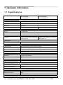
1
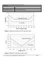
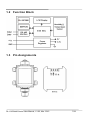
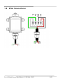
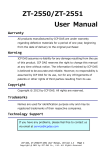
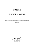
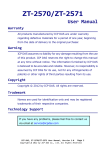
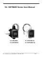
DL-100TM485 Series User Manual
‐ DL‐100TM485 ‐ DL‐100TM485‐W ‐ DL‐100TM485P ‐ DL‐100TM485P‐W DL-100TM485 Series User Manual, V1.02, Mar. 2015
1/23
Warranty
All products manufactured by ICP DAS are under warranty
regarding defective materials for a period of one year from the
date of delivery to the original purchaser.
Warning
ICP DAS assumes no liability for any damage resulting from the
use of this product. ICP DAS reserves the right to change this
manual at any time without notification. The information
furnished by ICP DAS is believed to be accurate and reliable.
However, no responsibility is assumed by ICP DAS for its use,
nor for any infringements of patents or other rights of third
parties resulting from its use.
Copyright
Copyright© 2014 ICP DAS. All rights reserved.
Trademarks
Names are used for identification purposes only and may be
registered trademarks of their respective companies.
DL-100TM485 Series User Manual, V1.02, Mar. 2015
2/23
Table of Contents
1
Hardware Information .................................................................................................. 5
1.1 Specifications ......................................................................................................... 5
1.2 Function Block........................................................................................................ 7
1.3 Pin Assignments..................................................................................................... 7
1.4 Wire Connections................................................................................................... 8
2 Modbus RTU Protocol ............................................................................................... 9
2.1 Modbus Mapping Table .......................................................................................... 10
3 Utility Software ........................................................................................................... 14
3.1 Before you use the Utility Software ........................................................................ 14
3.2 DL-100TM485 Utility............................................................................................... 15
3.3 Configuration .......................................................................................................... 16
3.4
Download Data .................................................................................................... 20
4 Appendix.................................................................................................................... 22
4.1 LCD Information: .................................................................................................... 22
DL-100TM485 Series User Manual, V1.02, Mar. 2015
3/23
Introduction
The DL-100TM485/DL-100TM485P/DL-100TM485-W/
DL-100TM485P-W is a one-channel temperature and humidity
data logger module. It contains a built-in RS-485 communication
interface and an LCD indicator to display the module ID,
temperature and humidity data, and allows you to define the log
time interval depending on your application.
The DL-100TM485 supports the Modbus RTU protocol. Refer to
Section 2 for more details.
We also provide software utility that can be used to retrieve log
data and display it in a chart on your desktop, and also allow you
save the log data into an Excel format file.
DL-100TM485 Series User Manual, V1.02, Mar. 2015
4/23
1 Hardware Information
1.1 Specifications
DL‐100TM485/ DL‐100TM485‐W DL‐100TM485P/ DL‐100TM485P‐W Temperature Measurement Range ‐20 ~ +60°C (‐31 ~ +176°F) Resolution 0.1°C Precision +/‐ 0.1°C Accuracy Typical: ±0.4°C (See Figure 2) Typical: ±0.3°C (See Figure 2) Humidity Measurement Range 0 ~ 100% RH Resolution 0.1% RH Precision +/‐ 0.1% RH Accuracy Typical: ±3% RH @ 20 ~ 80% RH
(See Figure 1) Typical: ±1.8% RH @ 10 ~ 90% RH (See Figure 1) LCD Display Displayed Information Temperature (°C and °F), Humidity (RH), Module ID Data Logger Max. Records 4088 temperature and humidity records Time Interval 10 seconds to 1 day Mode Overwrite or stop logging when storage space is full Overwrite Limitation 1,000,000 cycles Communication Interface RS‐485; non‐isolated Baudrate 1200 ~ 115200 bps Data Format N,8,1 Max. Modules on same bus 32 Power Input Range +10 ~ 30 VDC Power Consumption 0.15 W Mechanical Dimensions (W x L x H) 82 mm x 126 mm x 55 mm Waterproof Level IP66 Installation DIN‐Rail; Wall mount DL-100TM485 Series User Manual, V1.02, Mar. 2015
5/23
Environment Operating Temperature ‐20 ~ +60˚C Storage Temperature ‐30 ~ +80˚C Ambient Relative Humidity 5 ~ 95% RH, Non‐condensing DL-100TM485 Series User Manual, V1.02, Mar. 2015
6/23
1.2
Function Block
8-Bit MCU
1.3
Pin Assignments
DL-100TM485 Series User Manual, V1.02, Mar. 2015
7/23
1.4
Wire Connections
DL-100TM485 Series User Manual, V1.02, Mar. 2015
8/23
2 Modbus RTU Protocol
The Modbus protocol was originally developed for Modicon
controllers by Modicon Inc. Detailed information can be found at
http://www.modicon.com/techpubs/toc7.html. Visit
http://www.modbus.org to find more valuable information.
The DL-100TM485 module supports the Modbus RTU protocol.
The communication Baud Rate is 9600bps, and the parity, data
bits and stop bits are fixed as no parity, 8 data bits and 1 stop bit.
The following Modbus functions are supported.
Code
Description
Address
0x01
Read coils status
0xxxx
0x02
Read discrete inputs
1xxxx
0x03
Read multiple registers
4xxxx
0x04
Read multiple input registers
3xxxx
0x05
Write single coils
0xxxx
0x06
Write single register
4xxxx
0x0F
Write multiple coils
0xxxx
0x10
Write multiple register
4xxxx
If the function specified in the message is not supported, then the
module responds as follows.
Error
00
01
02
Response
Address
Function code
Exception code
1 Byte 1 ~ 247
1 Byte Function code + 0x80
1 Byte 01
If a CRC mismatch occurs, the module will not respond.
DL-100TM485 Series User Manual, V1.02, Mar. 2015
9/23
DL-100TM485
2.1
Modbus Mapping Table
DL-100TM485 Modbus RTU Tables
Coils
Number Address (Hex) Function Access
Code(s) Data Name Type
Comments 00257 256 (0x100) 01, 02, 05, 15 R/W Bit Enables or disables the logging Function. 0: Disabled 1: Enabled 00258 257 (0x101) 01, 02, 05, 15 R/W Bit Resets the value of the log records counter to 0. Set this bit to on to clear the log data counter value. This bit will be set to 0 when cleared successfully. 00259 258 (0x102) 01, 02, 05, 15 R/W Bit Set the page of the first log data which you want to read. There are two pages of log space available in the DL‐50M, and each page contains 32760 humidity and temperature data records. 10260 259 (0x103) 01, 02 R Bit Reset Bit. This bit only returns a value of 1 when you read it for the first time. In all other cases, it always returns a value of 0. 10261 260 (0x104) 01, 02 R Bit The page number where the first log data 0: First page record is stored. 1: Second page 10262 261 (0x105) 01, 02 R Bit The page number where the last log data record is stored. 0: First page 1: Second page DL-100TM485 User Manual, V1.00
10/23
DL-100TM485 Series User Manual, V1.02, Mar. 2015
9/23
DL-100TM485
Input Registers
Number Address (Hex) Function Access
Code(s) Data Type Name Comments 30001 0 (0) 03, 04 R Word Humidity value. The response value is the result of the original value multiplied by 100. 30002 1 (1) 03, 04 R Word Temperature value in degrees Celsius.
The response value is the result of the original value multiplied by 100. 30003 2 (2) 03, 04 R Word Temperature value in degrees Fahrenheit. The response value is the result of the original value multiplied by 100. 365521 65520 (FFF0) 03, 04 R Word Firmware version. The response value is a hex value. The high byte denotes major version, the low byte denotes minor version. 365522 65521 (FFF1) 03, 04 R Long HI Module Name. The response value is a hex value. The high byte denotes ‘D’, the low byte denotes ‘L’. 365523 65522 (FFF2) 03, 04 R Long LO Module Name. The response value is a hex value. The high byte denotes ‘0’, the low byte denotes ‘50’. 365524 65523 (FFF3) 03, 04 R Word The number of log records. DL-100TM485 User Manual, V1.00
11/23
DL-100TM485 Series User Manual, V1.02, Mar. 2015
10/23
DL-100TM485
Value
Time
Value
Time
Value
Time
Value
Time
0
10 seconds
3
1 minute
6
1 hour
9
6 hours
1
20 seconds
4
5 minutes
7
2 hours
0x0A
12 hours
2
30 seconds
5
10 minutes
8
6 hours
0x0B
1 day
Table 1
Holding Registers
365525 65524 (FFF4) 03, 04 06, 16 R/W 365526 65525 (0xFFF5)
03, 04 06, 16 R/W 365527 03, 04 06, 16 R/W 65526 (0xFFF6)
365528 65527 (0xFFF7)
03, 04 06, 16 R/W Byte The high byte: Module address 1~248 Bit The low byte: The logging mode. 0: The module will stop logging if the EEPROM memory is full. 1: The earliest stored data record will be overwritten if the EEPROM memory is full. Byte The high byte: LCD display items 00~3F The low byte: The logging time interval. The allowed range is from 0 to 0x0B. Refer to Table 1 for more information. The high byte: Module baud rate 06~07 06: 9600 bps; 07:19200 bps The low byte: The temperature offset value. The unit is 0.1 degrees in Celsius, the range is from ‐12.8℃ ~ 12.7℃. The starting address of the logging data record you want to read. The response value will be filled with 0x7777 when this value is higher than the last address. Sign Byte Word DL-100TM485
User Manual, V1.00 12/23
DL-100TM485 Series User Manual, V1.02, Mar.
2015
11/23
DL-100TM485
365529 65528 (0xFFF8)
03, 04 06, 16 R/W Byte The numbers of logging data records you want to read. The response value will be filled with 0x7777 when this value is higher than the last address. 65529 365530 (0xFFF9)
03, 04 06, 16 R/W Word The base year and month values. The response value is a hex value. The high byte denotes the ‘year’, the low byte denotes the ‘month’. 365531 65530 (0xFFFA)
03, 04 06, 16 R/W Word The base day and hour values. The response value is a hex value. The high byte denotes the ‘day’, the low byte denotes the ‘hour’. 365532 65531 03, 04 (0xFFFB) 06, 16 R/W Word The base minutes and seconds values.
The response value is a hex value. The high byte denotes the ‘minutes’, the low byte denotes the ‘seconds’. 365533 65522 (0xFFFC)
03, 04 06, 16 R/W Word The current year and month values. The response value is a hex value. The high byte denotes the ‘current year’, the low byte denotes the ‘the month’. 365534 65533 03, 04 (0xFFFD) 06, 16 R/W Word The current day and hour values. The response value is a hex value. The high byte denotes the ‘current day’, the low byte denotes the ‘current hour’. 365535 65534 (0xFFFE)
R/W Word The current minute and second values. The response value is a hex value. The high byte denotes the ‘current minute’, the low byte denotes the ‘current second’. 03, 04 06, 16 DL-100TM485 Series User Manual, V1.02, Mar.
2015
DL-100TM485
User Manual, V1.00 13/23
12/23
3 Utility Software
3.1 Before you use the Utility Software
1.
2.
3.
4.
Before you use this Utility, please make sure you have installed Microsoft .NET
Framework 4. If you haven’t installed .NET Framework yet, please refer to section 2 for
more information, or refer to section 3 for more information about the installation of this
Utility.
To download .NET Framework, refer:
http://www.microsoft.com/downloads/en/details.aspx?FamilyID=9cfb2d51-5ff4-4491-b0
e5-b386f32c0992&displaylang=en
You also can find the Microsoft .NET Framework 4 web installer package in the
following location on the enclosed CD
(Napdos\Net_FrameWork\dotNetFx40_Full_setup.exe).
The Utility software is located in the following location in product CD:
Napdos\DL_100\Utility
DL-100TM485 Series User Manual, V1.02, Mar. 2015
14/23
3.2 DL-100TM485 Utility
After launching the Utility, the program interface will be displayed, as shown
below:
icon opens a previous DL-100TM485
z Clicking “File” or the
logging data file stored on your PC.
z Clicking “Connection->Connect->RS-232/RS-485” or the
creates a connection from the serial port.
icon
icon disconnects the
z Clicking “Connection->Disconnect” or the
connection between the PC and the DL-100TM485.
z Clicking *“Functions->Get Records” or the
icon retrieves the
logging data which is stored in the EEPROM of the DL-100TM485
module.
z Clicking *“Functions->Configuration” or the
icon enables you to
configure the DL-100TM485 module.
z Clicking “Exit” or the
icon closes the Utility software.
*This function is only valid when a connection has been successfully
established between the PC and the DL-100TM485 module.
DL-100TM485 Series User Manual, V1.02, Mar. 2015
15/23
3.3 Configuration
1. Launch the DLUtility.exe
Connection status
2. Link with the DL-100TM485(P)
Select the COM port number,
Model Name and Module Address
(2-digit hexadecimal number) and
then click the OK button.
DL-100TM485 Series User Manual, V1.02, Mar. 2015
16/23
3. Configure the DL-100TM485(P)
Click on the icon to enter the configuration dialog window.
Connection status
Others Tab
1 3
2
1
On this tab you can
1. Set the temperature offset value: move the slide to select the temperature offset value
and then click on the Set button.
2. Set the LCD display information: check the checkboxes for those items to display on the
DL-100 logger and click on the Set button.
3. Read the time on the PC and set it into the DL-100 logger.
Click on the Set button to set the time on the PC to the DL-100.
Note
The time setting will be cleared the next time power is turned on.
DL-100TM485 Series User Manual, V1.02, Mar. 2015
17/23
Data Log Tab
1 2
4
3
2
On this tab you can
1. Enable/Disable data logging.
Select the Enable/ Disable radio button and then click on the Set button.
Note
The data logging will be disabled whenever the module is connected through the DLUtility.
Please enable the logging function before leaving the DLUtility.
2. Set the Log Mode: select the Mode 0/ Mode 1 radio button and click on the Set button.
Mode 0: stops data logger when the storage space is full.
Mode 1: continues data logger and overwrites the old data with the new data when the
storage space is full.
3. Set the time interval for data logging: move the slide to select the time interval and click
on the Set button.
The available time interval can be set is 10 seconds, 20 seconds, 30 seconds, 1 minute,
5 minutes, 10 minutes, 30 minutes, 1 Hour, 2 Hours, 6 Hours, 12 Hours and 24 Hours.
4. Read the number of data records or clear the data in the DL-100 logger.
DL-100TM485 Series User Manual, V1.02, Mar. 2015
18/23
Basic Tab
1 3
2
On this tab you can
1. Set the module address and communication parameters
Move the slide to select the module address, Baud Rate, Data Format and click the Set
button.
2. Read the real-time data
Check the Polling Data checkbox. Except the LCD Display Items on Others tab, all the
configuration functions will be disabled after the Polling Data checkbox is checked.
3. Read the firmware version for the DL-100 module.
DL-100TM485 Series User Manual, V1.02, Mar. 2015
19/23
3.4 Download Data
Connection status
1. Click on the Get button and click on the Yes button on the pop-up dialog boxes.
DL-100TM485 Series User Manual, V1.02, Mar. 2015
20/23
2. Check the Show chart checkbox to display a line chart of download data.
3. Click on the Save as file button to save the download data in a text file of extension filename.csv
or filename.txt file.
DL-100TM485 Series User Manual, V1.02, Mar. 2015
21/23
4 Appendix
4.1 LCD Information:
The LCD display information can be set from the Others tab on the Configuration dialog window as
below:
DL-100TM485 Series User Manual, V1.02, Mar. 2015
22/23
z Module Address:
①
②
Area
LCD value
Details
①
Id
②
00~FF
Indicates that the currently
displayed information is the
module address.
Indicates the current module
address, 01 in this example.
z Temperature Value
①
③
②
DL-100TM485 Series User Manual, V1.02, Mar. 2015
23/23
Area
LCD value
①
Indicates that the currently
icon
displayed information is the
temperature.
DDD.D~-DD.D Indicates the current
temperature value.
℃ or ℉ icon Indicates the temperature units.
②
③
Details
z Humidity Value
①
②
Area
①
③
LCD value
icon
②
DD.D
③
% icon
Details
Indicates that the currently
displayed information is the
humidity.
Indicates the current humidity
value.
Indicates the humidity units.
DL-100TM485 Series User Manual, V1.02, Mar. 2015
24/23