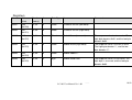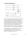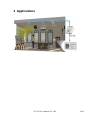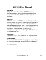
1
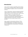
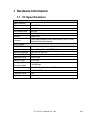
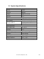
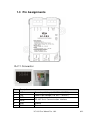
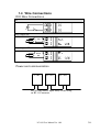
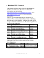
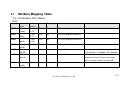
LC-103 User Manual
Warranty
All products manufactured by ICP DAS are under
warranty regarding defective materials for a period of
one year from the date of delivery to the original
purchaser.
Warning
ICP DAS assumes no liability for any damage resulting
from the use of this product. ICP DAS reserves the right
to change this manual at any time without notification.
The information furnished by ICP DAS is believed to be
accurate and reliable. However, no responsibility is
assumed by ICP DAS for its use, nor for any
infringements of patents or other rights of third parties
resulting from its use.
Copyright
Copyright© 1999 - 2011 ICP DAS. All rights reserved.
Trademarks
Names are used for identification purposes only and may
be registered trademarks of their respective companies.
Date: 2012/01/10
LC-103 User Manual Ver. 1.02
1/12
Table of Contents
LC-103 User Manual ......................................................................................................................1
Introduction ........................................................................................................................................3
1
Hardware Information....................................................................................4
1.1
IO Specifications .....................................................................................4
1.2
System Specifications.............................................................................5
1.3
Pin Assignments ......................................................................................6
1.4
Wire Connections ....................................................................................7
2
Modbus RTU Protocol ................................................................................8
2.1
Modbus Mapping Table .............................................................................9
3
Function Descriptions .................................................................................. 11
4
Applications .................................................................................................12
LC-103 User Manual Ver. 1.02
2/12
Introduction
The LC-103 is an easy-to-use lighting control module
that requires no specialist skills to install and operate,
and no software is needed in order to control the DO
channels.
The LC-103 provides 1 channel for digital input (photo
couple isolation) and 3 channels for relay output. All
output channels are form A type relays, while the input
channel is based on a sink-type using a wire
connection. The input channel can directly control a
3-channel relay ON and OFF sequence without
requiring a remote host controller. 4 kV ESD protection
and 5000 Vrms intra-module isolation are also
provided.
When required, communication with the LC-103 is
programmable based on the Modbus RTU protocol,
and an added benefit is that different addresses can
be set for Modbus RTU communication via hardware
configuration.
LC-103 User Manual Ver. 1.02
3/12
1 Hardware Information
1.1 IO Specifications
Digital Input
Input Channels
1
Type
90~240VAC
On Voltage Level
85 VAC
Off Voltage Level
60 VAC
Input Impedance
68 KΩ, 1 W
Isolation
5000 Vrms
Function
Local and Remote Direct Control Relay ON/OFF and
Remote Status Monitoring
Relay Output
Output Channels
3
Type
Power Relay, Form A (SPST N.O.)
Operating Voltage
250 VAC or 30 VDC
Max. Load Current
5A
Operating Time
10 ms Max.
Release Time
5 ms Max.
Electrical Life
(Resistive load)
100,000 ops
Mechanical Life
20,000,000 ops at no load (300 ops/minute)
Safety Approval
UL/CUL, TÜV
Power-on Value
No
Safe Value
No
LC-103 User Manual Ver. 1.02
4/12
1.2 System Specifications
Communication
Interface
RS-485
Format
N,8,1
Baud Rate
9600 bps
Protocol
Modbus RTU /DCON
Node Addresses
1~31
Connector
RJ-11
LED Indicators
Power
1 LED as Power Indicator
EMS Protection
ESD (IEC 61000-4-2)
EFT (IEC 61000-4-4)
±2 kV Contact for Each Terminal
±4 kV Air for Random Point
±2 kV for Power
Power Requirements
Input Voltage Range
10 ~ 30 VDC
Consumption
0.5 W Max.
Connector
RJ-11
Mechanical
Dimensions (W x L x H)
52 mm x 98 mm x 27 mm
Installation
Screw Mounting
Environment
Operating Temperature
-25°C ~ +75°C
Storage Temperature
-30°C ~ +75°C
Humidity
10 ~ 95% RH, Non-condensing
LC-103 User Manual Ver. 1.02
5/12
1.3 Pin Assignments
RJ-11 Connector
Pin
Descriptions
1
+VS
Power Input Voltage (+10 VDC ~ 30 VDC)
2
+VS
Power Input Voltage (+10 VDC ~ 30 VDC)
3
DATA+
4
DATA-
5
GND
Ground
6
GND
Ground
RS-485 Serial Communication Interface
LC-103 User Manual Ver. 1.02
6/12
1.4 Wire Connections
DIO Wire Connections
DI
Relay Output ON
Relay Output OFF
Power and communication
LC-103
LC-103
LC-103
RS-485 and Power Input Daisy Chain using
an RJ-11 Connector
LC-103 User Manual Ver. 1.02
7/12
2 Modbus RTU Protocol
The Modbus protocol was originally developed for
Modicon controllers by Modicon Inc. Detailed
information can be found at
http://www.modicon.com/techpubs/toc7.html. Visit
http://www.modbus.org to find more valuable
information.
The LC-103 module supports the Modbus RTU
protocol. The communication Baud Rate is 9600bps,
and the parity, data bits and stop bits are fixed as no
parity, 8 data bits and 1 stop bit. The following Modbus
functions are supported.
Code
Description
Address
0x01
Read coils status
0xxxx
0x02
Read discrete inputs
1xxxx
0x03
Read multiple registers
4xxxx
0x04
Read multiple input registers
3xxxx
0x05
Write to a single coils
0xxxx
0x06
Write toa single register
4xxxx
0x0F
Write to multiple coils
0xxxx
0x10
Write to multiple registers
4xxxx
If the function specified in the message is not
supported, then the module responds as follows.
Error Response
00
Address
1 Byte 1 ~ 247
01
Function code
1 Byte Function code + 0x80
02
Exception code 1 Byte 01
If a CRC mismatch occurs, the module will not respond.
LC-103 User Manual Ver. 1.02
8/12
2.1
Modbus Mapping Table
LC-103 Modbus RTU Tables
Coils
Number
Address
(Hex)
Function
Code(s)
Access
Data Type
Name
00001
0
(0x00)
01, 02,
05, 15
R/W
Bit
AC relay output of channel 0.
00002
1
01, 02,
R/W
Bit
AC relay output of channel 1.
(0x01)
05, 15
2
01, 02,
R/W
Bit
AC relay output of channel 2.
(0x02)
05, 15
00033
32
(0x20)
01, 02
R
Bit
AC input of channel 0.
00257
256
(0x100)
01, 02
R
Bit
Protocol indicator bit.
The response value is a hex value of 1
which denotes the Modbus RTU protocol.
00273
272
01, 02
R
Bit
Reset Bit.
This bit only returns a value of 1 when
00003
Comments
(0x110)
10001
0
(0x00)
reading it for the first time. In all other
cases, it always returns a value of 0.
01, 02
R
Bit
AC input of channel 0.
LC-103 User Manual Ver. 1.02
9/12
9/12
Registers
Number
Address
(Hex)
Function
Code(s)
Access
Data Type
Name
Comments
40481
480
(0x1E0)
03, 04
R
Word
Firmware Version (low word).
40482
481
(0x1E1)
03, 04
R
Word
Firmware Version (high word).
40483
482
(0x1E2)
03, 04
R
Word
Module Name (low word).
The response value is a hex value. The
high byte denotes 0x01, and the low byte
denotes 0x03.
40484
483
03, 04
R
Word
Module Name (high word).
The response value is the ASCII value.
(0x1E3)
The high byte denotes ‘L’, and the low
byte denotes ‘C’.
40485
484
(0x1E4)
03, 04
R
Word
Module Address..
40486
485
(0x1E5)
03, 04
R
Byte
Module Baud Rate.
LC-103 User Manual Ver. 1.02
The response value is a hex value. The
high byte is reserved, and the low byte
denotes 0x06.
10/12
10/12
3 Function Descriptions
The LC-103 has a single AC input that can be used to
connect a lighting control switch and three relay
outputs that can be used to connect the lighting, lamp
or AC LED lighting etc. Please refer to the above
diagram for detailed wire connection information. The
input channel of the LC-103 can directly control its
3-channel relay ON and OFF sequence without
requiring a remote host controller, so it’s very easy to
test any lighting circuits for incomplete applications.
If an application requires software control, such as
building automation or scenario control, etc.,
communication with the LC-103 is programmable
based on the Modbus RTU protocol.
LC-103 User Manual Ver. 1.02
11/12
4 Applications
LC-103 User Manual Ver. 1.02
12/12