1
User ’s Manual
LG Programmable Logic Controller
– TC4A
GLOFA G3F
G4F – TC2A
MASTER-K G6F – TC2A
L G Industrial Systems
REVISIONS
Date
2001.4.
REV. No
702004908
G6F-TC2A Module added
Description
SAFETY PRECAUTIONS
Be sure to read carefully the safety precautions given in data sheet and user’s manual before operating the module
and follow them.
The precautions explained here only apply to the G3F-TC4A , G4F-TC2A andG6F-TC2A.
For safety precautions on the PLC system, see the GLOFA GM3/4 User’s Manuals, GLOFA GM6 User’s Manuals
or the MASTER-K 1000S/300S/200S User’s Manuals.
A precaution is given with a hazard alert triangular symbol to call your attention, and precautions are represented
as follows according to the degree of hazard.
!
WARNING
If not provided with proper prevention, it can cause death or fatal
injury or considerable loss of property.
!
CAUTION
If not properly observed, it can cause a hazard situation to result
in severe or slight injury or a loss of property.
However, a precaution followed with
!
can also result in serious conditions.
CAUTION
Both of two symbols indicate that an important content is mentioned, therefore, be sure to observe it.
Keep this manual handy for your quick reference in necessary.
Design Precautions
!
CAUTION
▶ Do not run I/O signal lines and compensating wires near to high voltage line or
power line.
Separate them as 100 mm or more as possible.
Otherwise, noise can cause module malfunction.
Installation Precautions
!
Wiring Precautions
!
CAUTION
▶ Operate the PLC in the environment conditions given in the
general specifications.
▶ If operated in other environment
not specified in the general
specifications, it can cause an
electric shock, a fire, malfunction
or damage or degradation of the
module
▶ Make sure the module fixing
projections is inserted into the
module fixing hole and fixed.
▶ Improper installation of the module can cause malfunction, dis order or falling.
CAUTION
▶ When grounding a FG terminal,
be sure to provide class 3
grounding which is dedicated to
the PLC.
▶ Before the PLC wiring, be sure to
check the rated voltage and terminal arrangement for the module and observe them correctly.
If a different power, not of the
rated voltage, is applied or
wrong wiring is provided, it can
cause a fire or disorder of the
nodule.
▶ Drive the terminal screws firmly
to the defined torque.
If loosely driven, it can cause
short circuit, a fire or malfunction.
▶ Be careful that any foreign matter
like wire scraps should not enter
into the module.
It can cause a fire, disorder or
malfunction.
Test Run and Maintenance
Precautions
!
!
WARNING
▶ Do not contact the terminals
while the power is applied.
It can cause malfunction.
▶ When cleaning or driving a terminal screw, perform them after the
power has been turned off
▶ Do not perform works while the
power is applied, which can
cause disorder or malfunction.
CAUTION
▶ Do not separate the module from
the printed circuit board(PCB), or
do not remodel the module.
They can cause disorder, malfunction, and damage of the
module or a fire.
When mounting or dismounting
the module, perform them after
the power has been turned off.
▶ Do not perform works while the
power is applied, which can
cause disorder or malfunction.
Waste Disposal Precautions
!
CAUTION
▶ When disposing the module, do it as an industrial waste.
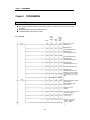
CONTENTS ◎
◎
Chapter 1. INTRODUCTION
1.1
1.2
Features
··············································································································································1-1
Glossary ················································································································································1-2
1.2.1
A-Analog Value ·····························································································································1-2
1.2.2 D-Digital Value ······························································································································1-2
1.2.3 Compensating Wire ····················································································································1-2
1.2.4
Thermocouple
·····························································································································1-3
1.2.5 Temperature Conversion Characteristics
1.2.6
···················································································1-3
Burn-out Detection ······················································································································1-3
1.2.7 Reference Junction Compensation (RJC) ··················································································1-3
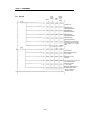
Chapter 2. SPECIFICATIONS
2.1
General Specifications
······················································································································2-1
2.2
Performance Specifications
···········································································································2-2
2.3 Names of Parts and Functions
·········································································································2-3
2.3.1
G3F-TC4A
··································································································································2-3
2.3.2
G4F-TC2A ·····································································································································2-4
2.3.3
G6F-TC2A ·····································································································································2-4
2.4 I/O Conversion Characteristics
········································································································2-5
2.4.1
Temperature Conversion Characteristics
···················································································2-5
2.4.2
Conversion Speed
2.4.3
2.4.4
Accuracy
···································································································································2-6
Burn-out Detection
···················································································································2-6
······················································································································2-5
2.4.5 Displaying Temperature Conversion Value
2.4.6 Displaying Digital Value
················································································2-7
··············································································································2-7
Chapter 3. INSTALLATION AND WIRING
3.1
Installation
········································································································································3-1
3.1.1 Installation Ambience······················································································································3-1
3.1.2 Handling Precautions
3.2
Wiring
3.2.1
···············································································································3-1
················································································································································3-2
Wiring Precautions
···················································································································3-2
Chapter 4. FUNCTIONS BLOCKS
4.1
Insertion of the Function Blocks for Thermocouple Input Module on the GMWIN
4.2
Local Function Block ························································································································4-2
4.2.1
··················4-1
Module Initialization (G3F-TC4A: TC4INI, G4F-TC2A/G6F-TC2A: TC2INI) ··································4-2
4.2.2 Module Reading (Array Type) (G3F -TC4A:TC4ARD, G4F- TC2A/G6F-TC2A:TC2ARD) ·············4-3
4.2.3 Module Reading (Stand-alone Type) (G3F-TC4A : TC4RD, G4F-TC2A/G6F-TC2A:TC2RD)······4-4
4. 3 Remote Function Block ·························································································································4-5
4.3.1
Module Initialization (G3F-TC4A: TCR4INI, G4F-TC2A:TCR2INI, G 6F-TC 2A:TCR62INI)
4.3.2
Module Reading (Array Type)
(G3F-TC4A:TCR4RD, G4F-TC2A:TCR2RD, G6F-TC2A:TCR62RD)
········4-5
······································4-6
4.4 Errors Indicated During Execution Of Function Block ··································································4-7
4.4.1 Errors Indicated by the Output Variable,STAT ···········································································4-7
4.4.2 Errors Indicated by the Output Variable,ALM_CODE in the array type temperature Converstion
value reading function block(G3F-TC4A:TC4ARD,TCR4RD,G4F -TC2A:TC2ARD,TCR2RD G6FTC2A:TC2ARD,TCR62RD)·············································································································4-7
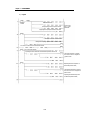
Chapter 5. PROGRAMMING
5.1 A Program for Converting a Detected Temperature Value(° C) into
Fahrenheit (° F) and Outputting as a BCD Value ···············································································5-1
5.2 A Program for Magnitude Comparison of a Detected Temperature Value
5.3
····································5-6
A Program Used When Mounting a Thermocouple Input Module
on the Remote I/O Station ···················································································································· 5-9
Chapter 6. BUFFER MEMORY CONFIGURATION AND FUNCTIONS
6.1
6.2
Buffer Memory Configuration
········································································································6-1
6.1.1
G3F-TC4A Buffer Memory
6.1.2
G4F-TC2A/G6F-TC2A Buffer Memory ·······················································································6-3
Buffer Memory Functions
·······································································································6-1
···············································································································6-4
6.2.1 Specifying Channel Enable/Disable
(G3F-TC4A : Address 0, G 4F-TC2A/G6F-TC2A : Address 0)
6.2.2
····················································6-4
Specifying the Type Of Thermocouple
(G3F-TC4A : Address 1 To 16, G 4F-TC2A G6F -TC2A : Address 1 to 4)
6.2.3 Temperature Conversion Value
···································6-4
··································································································6-5
6.2.4
Digital Conversion Value
············································································································6-5
6.2.5
Error Code
6.2.6
Setting SET Data (G3F-TC4A : Address 65, G 4F-TC2A G6F-TC2A : Address 17) ····················6-6
··································································································································6-6
6.2.7 Information on Run Channel (G3F-TC4A : Address 66, G4F-TC2A/G6F-TC2A : Address 18)·····6-7
6.2.8 Information on Thermocouple Type Specification Error
(G3F-TC4A : Address 67, G 4F-TC2A /G6F-TC2A : Address 19)
Chapter 7.
7.1
·············································6-7
DEDICATED INSTRUCTIONS FOR SPECIAL MODULES (Read from/Write to Buffer Memory)
Local
····················································································································································7-1
7.1.1 Read from Buffer Memory.....GET, GETP ····················································································7-1
7.1.2 Write to Buffer Memory..........PUT, PUTP ····················································································7-2
7.2
Remote ····················································································································································7-3
7.2.1
Read from Buffer Memory.....RGET································································································7-3
7.2.2 Write to Buffer Memory..........RPUT·······························································································7-4
Chapter 8. PROGRAMMING
8.1
Basic Programming
··························································································································8-1
8.1.1
G3F-TC4A
································································································································8-1
8.1.2
G4F-TC2A
································································································································8-2
8.2
Application Program ming
8.2.1
·················································································································8-3
A Program for Conversing a Detected Temperature Value(°C)
into Fahrenheit (°F) and Outputting as a BCD Value ······························································8-3
8.2.2
A Program for Magnitude Comparison of a Detected Temperature Value ······························8-5
8.2.3
A Program Used When Mounting a Thermocouple Input Module
on the Remote I/O Station
································································································8-7
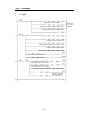
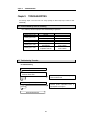
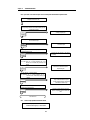
Chapter 9. TROUBLESHOOTING
9.1
Errors Indicated by Run LED Flickering····························································································9-1
9.2
Troubleshooting Procedure················································································································9-1
9.2.1
RUN LE D Flickering ························································································································9-1
9.2.2
RUN LE D O ff···································································································································9-2
9.2.3 Temperature Conversion Value Fluctuates Excessively ····························································9-2
9.2.4 Input Value of the Thermocouple does not
Correspond to the Detected Temperature Value ·········································································9-3
9.2.5 The LED Display of G3F-TC4A Indicates Error
······································································· 9-4
9.2.6 Thermocouple Input Module Hardware Defect
··········································································9-4
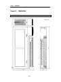
Chapter 10. DIMENSIONS
10.1
G3F-TC4A Dimensions
·············································································································· 10-1
10.2
G4F-TC2A Dimensions
··············································································································10-2
10. 3
G6F-TC2A Dimensions
··············································································································10-3
● Appendix
APPENDIX 1
1.1
Thermoelectromotive Force Tables
1.2
Thermocouple
································································································A-1
···································································································································A-5
1.2.1 Normal and Overheat Temperature Limits
1.2.2
Temperature Tolerances
1.3 Compensating Wire
················································································A-5
············································································································A-6
··························································································································A-7
1.3.1 Types and Specifications of Compensating Wire ······································································A-7
Chapter 1. INTRODUCTION
Chapter 1.
INTRODUCTION
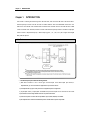
This manual is a learning and reference guide for the G3F-TC4A , G4F-TC2A and G6F-TC2A. The G3F-TC4A is a
thermocouple input module used with the CPU of GLOFA GM1/2/3 series and MASTER-K 1000S series .The
G4F-TC2A is used with the CPU of GM4 series and K300S series The G6F-TC2A is used with the CPU of GM6
series and K200S series. Hereafter, the three modules called thermocouple input module. The thermocouple input
module converts a temperature input by a thermocouple (Type K, J, E, T, B, R or S) into a signed 16-bit digital
binary data and outputs it.
1.1 Features
Temperature
Data
Buffer memory
temperature
conversion value
①
②
③
:
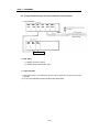
▶ The thermocouple input module has following features.
1) With direct connection of one of seven types of thermocouple to the thermocouple input module, a
temperature data (°C) can be converted into a digital value to be processed in the PLC
2) The temperature data (°C) input can be processed to one digit after the point as a digital value.
3) 16 point (G3F -TC4A) or 4-point (G4F -TC2A/G6F-TC2A) of thermocouple can be connected to one module.
4) Disconnection and Out-of-range detection function for every channel are included
5) The thermocouples in accordance with five specifications (KS, JIS, ANSI, DIN, BS) are available.
6) The temperature sensor loaded onto terminal block performs automatic reference junction compensation.
1 -1
Chapter 1. INTRODUCTION
1.2 Glossary
Number of man
A - Analog Value
Temperature
1.2.1
time
time
[Fig.1.1] Analog Value
[Fig.1.2] Digital Value
Continuous changeable quantity such as voltage, current, temperature, velocity, pressures and flux is
c alled an analog quantity. For example, temperature changes continuously with time as shown in Fig.
1.1. The PLC can process that continuous changeable temperature by use of the thermocouple input
module.
1.2.2
D - Digital Value
In the Fig.1.2, the number of man can be counted as 0, 1, 2 and 3. A discontinuous changeable
quantity as such is called a digital quantity. On and Off signals can be denoted as a digital value 0 and
1, respectively.
A/D
Conversion
CPU
(Digital
processing)
An analog quantity cannot be directly input to the
D/A
Conversion
CPU module for digital processing. Therefore, an
analog value should be converted into a digital
Analog
-200~-1200℃
400~1800 ℃
0~1750℃
Analog
0~±10 V
or
4~20 mA
value to be input to the CPU module. In addition,
for external output of an analog quantity, a digital
quantity of the CPU module should be converted
[Fig. 1.3] Processing in the PLC
into an analog quantity.
1 -2
Chapter 1. INTRODUCTION
1.2.3
Compensating Wire
This means a wire used to compensate error (temperature change) by the distance between terminal
of an input thermocouple and input terminal of a thermocouple input module. This has the
thermoelectromotive force characteristics between the two terminals under the temperature of 90 to
150 °C or less.
1.2.4
Thermocouple
If two different metals are joined and two different temperatures are applied to the two junctions, the
temperature difference generates a thermoelectromotive force between them and thermal current flows.
This effect called thermoelectric effect. Thermocouple is a temperature sensor using thermoelectric
effect. The magnitude of a thermoelectric force is determined by the type of junction metals and
temperature difference between two junctions, and the shape and dimensions of metals and
intermediate temperature change do not influence it.
1.2.5 Temperature Conversion Characteristics
The thermoelectromotiv e force to a temperature of a thermocouple has non-linear characteristics,
therefore, linear processing should be applied to a A/D conversion digital value and it will be output as
a detected temperature value.
1.2.6
Burn-out Detection
If a connected thermocouple or compensating wire has disconnection in some part of them, the internal
burn out circuit measures an out of range-voltage and then the thermocouple input module detects the
disconnection.
1.2.7 Reference Junction Compensation (RJC)
As the thermoelectromotive force table of various specifications has 0°C as its reference, the
difference between the present temperature at measuring point (input terminal) and the reference
temperature (0°C) should be compensated.
1 -3
Chapter 2 SPECIFICATIONS
Chapter 2.
SPECIFICATIONS
2.1 General Specifications
Table 2.1 shows general specifications of the GLOFA GM series and MASTER-K series.
No
1
2
3
4
Items
Specifications
Operating ambient
temperature
Storage ambient
temperature
Operating ambient
humidity
Storage ambient
humidity
5
Vibration
6
Shocks
7
Noise immunity
0 ~ 55℃
-25 ~ 70℃
5 ~ 95%RH, non-condensing
5 ~ 95%RH,
9
Operating
atmosphere
Altitude for use
10
11
Pollution degree
Cooling method
non-condensing
Occasional vibration
Acceleration
Amplitude
Sweep
count
0.075 mm
9.8 ㎨ {1G}
10 times in
IEC 61131-2
Continuos vibration
each direction for
Frequency
Acceleration
Amplitude
X, Y, Z
10≤f∠ 57 Hz
0.035 mm
57≤f≤150 Hz
4.9 ㎨ {0.5G}
*Maximum shock acceleration: 147 ㎨ {15G}
*Duration time :11 ms
IEC 61131-2
*Pulse wave: half sine wave pulse( 3 times in each of X, Y and Z directions )
LGIS
Square wave impulse noise
±1,500 V
Standard
IEC 61131-2
Electrostatic discharge
Voltage :4 kV(contact discharge)
IEC1000-4-2
IEC 61131-2
Radiated electromagnetic field
27 ~ 500 MHz, 10 V/m
IEC 1000-4-3
Frequency
10≤f∠ 57 Hz
57 ≤f≤ 150 Hz
Fast transient burst noise
8
Standard
Severity
Level
All power
modules
Digital
I/Os
( Ue
≥
24 V)
Voltage
2 kV
1 kV
Digital I/Os
(Ue < 24 V)
Analog I/Os
communication I/Os
0.25 kV
Free from corrosive gases and excessive dust
Up to 2,000m
2 or lower
Self-cooling
[Table 2.1 ] General specifications
REMARK
1) IEC(International Electrotechnical Commission)
: The international civilian organization which produces standards for electrical and electronics industry.
2) Pollution degree
: It indicates a standard of operating ambient pollution level.
The pollution degree 2 means the condition in which normally, only non-conductive pollution occurs.
Occasionally, however, a temporary conductivity caused by condensation shall be expected.
2- 1
IEC 61131-2
IEC1000-4-4
Chapter 2 SPECIFICATIONS
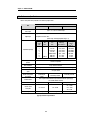
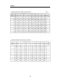
2.2 Performance Specifications
Table 2.2 shows performance specifications of the thermocouple input module.
Item
Specifications
G3F-TC4A
G4F-TC2A
Connectable
thermocouple
G6F-TC2A
Type K, J, E, T, B, R or S thermocouple
Digital conversion value : 0 to 16,000
Digital output
Temperature conversion value :
(thermocouple measuring temperature range×10)
Temperature input range
Thermocouple
type
K
J
E
T
B
R
S
DIN
Spec.
BS
Spec.
Measuring
temp. range(°C)
NiCr-Ni
PtRh-Pt
NiCr-NiAl
Pe-CuNi
NiCr-CuNi
Cu-CuNi
PtRh30-PtRh6
PtRh13-Pt
PtRh10-Pt
-200.0 ~1200.0
-200.0 ~800.0
-150.0 ~600.0
-200.0 ~400.0
400.0 ~1800.0
0.0 ~1750.0
0.0 ~1750.0
Reference junction com-
Automatic compensation
pensation
Burn-out detection
Accuracy
Every channel has detected.
±[ Full scale ×0.3 % + 1°C (Reference junction compensation tolerance)]
Maximum conversion
50 ms per channel
speed
Number of temperature
input channel
Insulation method
Connection terminal block
Internal current
consumption
Weight
Measuring
voltage
range(µV)
-5981~48828
-7890~45498
-7297~45085
-5602~20869
786~13585
0~21006
0~18612
16 channels per
module
4 channels per module
4 channels per module
Photo-coupler insulation between the input terminal and the PLC power supply
38-point terminal block
(non-insulation between channels)
20-point terminal block
18-point terminal block
+5V : 100 ㎃
+5V : 450 ㎃
+5V : 450 ㎃
640 g
360 g
[Fig. 2.2] Performance Specifications
2- 2
+15V : 40 ㎃
-15V : 20 ㎃
170 g
Chapter 2 SPECIFICATIONS
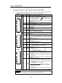
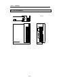
2.3 Names of Parts and Functions
The following gives names of parts :
2.3.1
G3F-TC4A
The following gives the names and functions of each part of the G3F-TC4A.
No
①
Contents
RUN LED
It displays the operating status of G3F-TC4A
l
l
②
②
On
: Normal Operation
Flickering: Error occurred (For details, refer to
Troubleshooting Section 9.1)
l
Off
: 5 VDC disconnection or the G3F-TC4A
module H/W error
Reference junction compensation device
Reference junction compensation for type K, J, E, T, R or S.
2- 3
Chapter 2 SPECIFICATIONS
2.3.2
G4F-TC2A
The following gives the names and functions of each part of the G4F-TC2A.
①
No
①
Contents
RUN LED
It displays the operating status of G4F-TC2A
l
l
②
②
On
: Normal Operation
Flickering: Error occurred (For details, refer to
Troubleshooting Section 9.1)
l
Off
: 5 VDC disconnection or
the G4F-TC2A module H/W error
Reference junction compensation device
Reference junction compensation for type K, J, E, T, R or S.
]
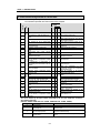
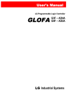
2.3.3
G6F-TC2A
The following gives the names and functions of each part of the G6F-TC2A.
RUN
①
No
Contents
G6F - TC2A
G6F-TC2A
①
RJ
②
CH0
CH1
CH2
CH3
+
+
+
+
-
FG
INPUT
TYPE:K,J,
E,T,R,S,B
RUN LED
It displays the operating status of G6F-TC2A
l
l
②
On
: Normal Operation
Flickering: Error occurred (For details, refer to
Troubleshooting Section 9.1)
l
Off
: 5 VDC disconnection or
the G6F-TC2A module H/W error
Reference junction compensation device
Reference junction compensation for type K, J, E, T, R or S.
2- 4
Chapter 2 SPECIFICATIONS
2.4 I/O Conversion Characteristics
The temperature that the thermocouple detected is input to each channel as a thermoelectromotive force.
Every channel is scanned at every measuring cycle and each input voltage is output as a temperature
conversion value through A/D conversion.
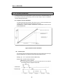
2.4.1 Temperature Conversion Characteristics
The thermocouple input module performs A/D conversion of the non-linear characteristic thermocouple input value and outputs the linear-processed temperature conversion value.
The following Fig. 2.1 shows an example of characteristics of the temperature conversion value to
the thermocouple input value.
Characteristics between linearized
temperature and thermoelectromotive force
℃
[Fig. 2.1] Temperature conversion characteristics
2.4.2 Conversion Speed
The conversion speed of the thermocouple input module is 50 ms per channel and its processing is
processed sequentially, that is, one channel is processed and then another channel is processed.
Measuring cycle = 50 ms×(the number of conversion enabled channels)
Example) When 10 channels are used in the G3F-TC4A
Measuring cycle = 50 ms×10 = 500 ms
That is, at every interval of 500ms, every thermocouple input value of every channel is
A/D converted and output as a temperature conversion value
2- 5
Chapter 2 SPECIFICATIONS
2.4.3
Accuracy
The accuracy of the thermocouple input module is within ± 0.3 % of all of the measuring temperature range and error (±1°C) from reference junction compensation is added.
Example) When a thermocouple type K is used, the detected temperature values to temperatures
–200 °C, 500°C and 1200°C are as below.
• Overall measuring temperature range of the K type: 1400 °C ( -200.0°C to 1200.0°C)
• Accuracy of the K type: 1400°C×±0.003 = ±4.2°C
• Accuracy including the error of reference junction compensation : 4.2 ± 1 = ±5.2°C
• Temperature conversion range : - 205.2 °C to – 194.8 °C when –200°C
494.8°C to 505.2°C when 500°C
1294.8°C to 1205.2°C when 1200°C
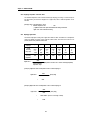
2.4.4
Burn-out Detection
This function detects disconnection of the thermocouple or compensating wire connected to the
thermocouple input module. As shown in the Fig. 2.2, if disconnection occurs in the thermocouple
or compensating wire the internal disconnection detection circuit measures an out-of-range voltage
and occurs disconnection error codes. Disconnection detection function is automatically performed
on every channel.
[Fig. 2.2] Disconnection Detection Area
2- 6
Chapter 2 SPECIFICATIONS
2.4.5 Displaying Temperature Conversion Value
The detected temperature value converted into through sampling processing of a thermocouple input value times by ten and that is displayed as a digital value, which is called temperature conversion value.
[Example] When a real temperature is 100.5°C
• Detected temperature value
: 1005
( Digital value stored in the output variable TEMP of the reading function block.
Digital value stored in the internal memory)
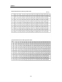
2.4.6 Displaying Digital Value
The thermocouple input module gives a digital value which has been calculated from a temperature
value to be suitable for process control of the PID control module. This value can be used as an input value (Process Value) in the PID control module.
Thermocouple type
Type K
Type J
Type E
Type T
Type B
Type R
Type S
Overall
measuring
temp. range
14000
(-2000
to
12000)
10000
(-2000
to
8000)
7500
(-1500
to
6000)
6000
(-2000
to
4000)
14000
(4000
to
18000)
17500
(0
to
17500
17500
(0
to
17500)
Minimum
measuring
temperature
-2000
-2000
-1500
-2000
4000
0
0
Digital value =
16000
(temperature conversion value – minimum measuring temperature)
Overall measuring
temperature range
[Example 1] Digital value when a real temperature is 400°C of thermocouple type J.
16000
Digital value =
[4000-(-2000)]
10000
=
9600
[Example 2] Digital value when a real temperature is 700°C of thermocouple type K.
16000
Digital value =
14000
=
[7000-(-2000)]
10285.71428571 (round off at first digit of fraction)
=
10268
2- 7
Chapter 3. INSTALLATION AND WIRING
Chapter 3.
INSTALLATION AND WIRING
3.1 Installation
3.1.1
Installation Ambience
This module has high reliability regardless of its installation ambience. But be sure to check the
following for system in higher reliability and stability.
1) Ambience Requirements
Avoid installing this module in locations, which are subjected or exposed to:
- Water leakage and dust a large amount of dust, powder and other conductive power, oil mist, salt, of
organic solvent exists.
- Mechanical vibrations of impacts are transmitted directly to the module body.
- Direct sunlight.
- Dew condensation due to sudden temperature change.
- High or low temperatures (outside the range of 0 to 55 °C)
2) Installing and Wiring.
- During wiring or other work do not allow any wire scraps to enter into it.
- Install it on locations that are convenient for operation.
- Make sure that it is not located near high voltage equipment located..
- Make sure that the distance from the walls of duct and external equipment be 50 mm or more.
- Be sure to be grounded to locations that have good ambient noise immunity.
3.1.2 Handling Precautions
▶ From unpacking to installing the thermocouple input module, be sure to check the following:
1) Do not drop it off, and make sure that strong impacts should not be applied.
2) Do not dismount printed circuit boards from the case. It can cause malfunctions.
3) During wiring, be sure to check any foreign matter like wire scraps should not enter into the upper
side of the module, and in the event that foreign matter entered into it, always eliminate it.
4) Be sure to disconnect electrical power before mounting or dismounting the module.
3- 1
Chapter 3. INSTALLATION AND WIRING
3.2 Wiring
3.2.1 Wiring Precautions
1) Be sure to use compensating wire for sensor input wire and connect shield wire to the terminal FG
and ground.
2) Be sure to separate the external input signal of the temperature conversion module from an
alternating current so that surge or induction noise generated from the alternating current could not
effect.
3) When wiring, locating this unit too near from high temperature generating devices or materials or
contacting it with the material like oil can cause short-circuit and occur damage or disorder.
4) When wiring to the terminal block, wiring with high-pressure wire or power supply wire can cause
flow inhibition and cause disorder or malfunction.
3.2.2 Wiring Example
A wiring example of the thermocouple input module is given below.
∗1 ▶ Use compensating wire as cable.
∗2 ▶ Connect shield wire part of compensating wire to the terminal FG and ground.
3- 2
Chapter 4. FUNCTION BLOCKS
Chapter 4.
FUNCTION BLOCKS
The followings explain the function blocks for the thermocouple input module used on the GMWIN
The types of function block are given here.
No
G3F-TC4A
G4F-TC2A
G6F -T C 2 A
Local
Remote
Local
Remote
Local
Remote
1
TC4INI
TCR4INI
TC2INI
TCR2INI
TC2INI
TCR62INI
2
TC4ARD
TCR4RD
TC2ARD
TCR2RD
TC2ARD
TCR62RD
3
TC4RD
-
TC2RD
-
TC2RD
-
Function
Module Initialization
Reading the temperature
conversion value
(Array type)
Reading the temperature
conversion value
(Single type)
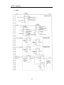
4.1 Insertion of the Function Blocks for the Thermocouple Input Module on the GMWIN.
Function blocks can be registered with the following procedure while the GMWIN is running.
Insertion of the function blocks is only possible when a project is open.
Project (P)
Selection
Library Insert (I)
G3F-TC4A
1. Special. 3fb
• TC4INI
• TC4ARD
• TC4RD
2. Remote3.3fb
• TCR4INI
• TCR4RD
3. Remote4.3fb
• TCR2INI
• TCR2RD
G4F-TC2A
1. Special. 4fb
• TC2INI
• TC2ARD
• TC2RD
2. Remote4.4fb
•TCR2INI
• TCR2RD
3. Remote3.4fb
• TCR4INI
• TCR4RD
Inserting local
function block
Inserting GM3 remote
function block
Inserting GM4 remote
function block
Inserting local
function block
Inserting GM4 remote
function block
Inserting GM3 remote
function block
4 -1
Chapter 4. FUNCTION BLOCKS
4.2 Local Function Block
4.2.1 Module Initialization (G3F-TC4A: TC4INI, G4F-TC2A/G6F-TC2A:TC2INI)
Module initialization function block specifies thermocouple input module base location, slot location,
run channel enable/disable and the type of thermocouple for use in program.
Function
Block
I/O
I
Variable
Data
Type
REQ
BOOL
BASE
USINT
SLOT
USINT
CH
BOOL
[Array]
TYPE
*Note 1
USINT
[Array]
*Note 1
G4F-TC2A/
G6F-TC2A
O
DONE
BOOL
STAT
USINT
ACT
BOOL
[Array]
*Note 1
Description
Function block execution request area
- Used to request an execution of the initialization function block
- If the conditions connected with this area are established and “0” changes into “1”
while program is running, the initialization function block is executed
Base location No.
- Used to write the base No. where the thermocouple input module is mounted.
- Setting range: GM1 series(0~31), GM2 series(0~7), GM3/4 series(0-3), GM6
series(0-1)
Slot location No.
- Used to write the slot No. where the thermocouple input module is mounted.
- Setting range: 0~7
Used channel enable/disable specification
- Used to enable or disable a channel for run.
- Specify “1” for enabling, and “0” for disabling
Specifying the type of the sensor to be connected
- Used
specify the type
to each channel.
Inputtospecification
No. of sensor
Sensorconnected
type
Temperature
range
0
K
-200.0 to 1200.0°C
1
J
-200.0 to 800.0°C
2
E
-150.0 to 600.0°C
3
T
-200.0 to 400.0°C
4
B
400.0 to 1800.0°C
5
R
0.0 to 1750.0 °C
6
S
0.0 to 1750.0°C
Function block finished execution status
- “1” is output when the initialization function block is finished with no error and
“1” remains until next execution. If an error occur, ‘0’ is displayed and the
operation enters into the stop state.
Error status indication area
- Used to output the error No. when it occurs during initialization function block
execution.
- For description of errors, refer to the Section 4.4
Run channel status indication area
- After the initialization function block is finished with no error, “1” is output if the
channel is in normal state. But “0” is output for the disabled channels.
REMARK
∗Note 1 [Array]
: The numbers of Array are 16 in G3F-TC4A, 4 in G4F-TC2A/G6F-TC2A.
4 -2
Chapter 4. FUNCTION BLOCKS
4.2.2 Module Reading (Array type) (G3F-TC4A : TC4ARD, G4F-TC2A/G6F -TC2A : TC2ARD)
The Array type module reading function block executes all channels of the thermocouple input module
in batch processing. If a channel is enabled then the function block outputs the temperature conversion
value to the output value TEMP.
Function
Block
I/O
Variable
I
Data
Type
REQ
BOOL
BASE
USINT
SLOT
USINT
CH
BOOL
[Array]
DONE
BOOL
*Note 1
O
STAT
G4F-TC2A/
G6F-TC2A
USINT
ACT
BOOL
[Array]
ALM
BOOL
[Array]
*Note 1
*Note 1
ALM_
CODE
USINT
[Array]
TEMP
INT
[Array]
*Not e 1
*Note 1
SCAL
INT
[Array]
*Note 1
Description
Function block execu tion request area
- Used to request an execution of the reading function block
- If the conditions connected with this area are established while the program is
running and “0” changes into “1”, the reading function block is executed.
Base location No.
- Used to write the base No. where the thermocouple input module is mounted.
- Setting range: GM1 series(0~31), GM2 series(0~7), GM3/4 series(0-3), GM6
series(0-1)
Slot location No.
- Used to write the slot No. where the thermo couple input module is mounted.
- Setting range: 0~7
Run channel enable/disable specification
- Used to enable or disable a channeI for run.
- Specify “1” for enabling, and “0” for disabling
Function block finished execution status
- “1” is output when the reading function block is finished with no error and “1”
remains until next execution. If an error occur,‘0’ is displayed and the operation
enters into the stop state.
Error status indication area
- Used to output the error No. when it occurs during reading function block
execution.
- For description of errors, refer to Section 4.4
Run channel status indication area
- After the reading function block is finished with no error, “1” is output if the
channel is in normal state. But “0” is output for the disabled channels.
Run channel error indication area
- “1” is outputted when error occurs for each run channel.
Run channel error code area
-Outputs the following code for each channel coded if error occurred.
0: Normal
16: Disconnection detected
17: Out-of-the-measuring-range error
18: Reference junction compensation device error
Temperature conversion value output area
- The CPU module reads the temperature conversion value of the corresponding
channel from the thermocouple input module and outputs it to this area.
- The temperature conversion value of each channel is 10 times than the real
temperature value.
- (Example: Temperature conversion value 1234 → Real temperature value
123.4°C)
Digital conversion value output area
- The CPU module reads the digital conversion value of the corresponding cha nnel
from the thermocouple input module and outputs it to this area.
- The temperature conversion value of each channel within its measuring
temperature range is converted into a digital value within 0 to 16000 and it is
outputted to this area.
The Value read from the output variable SCAL.
16000
×(Temperature conversion value–
Overall measuring
Minimum measuring temperature)
temperature range
- The output value through digital conversion can be used as a PV of the PID
control module.
REMARK
∗Note 1: The numbers of Array are 16 in G3F-TC4A, 4 in G4F-TC2A/G6F-TC2A .
4 -3
Chapter 4. FUNCTION BLOCKS
4.2.3 Module Reading (Stand-alone type)
The stand-alone type module reading function block outputs the temperature conversion value to which
each channel of the thermocouple input module is set to output variable TEMP.
Function
Block
I/O
Variable
Data
Type
I
REQ
BOOL
BASE
USINT
SLOT
USINT
CH
G4F-TC2A/
G6F-TC2A
USINT
O
DONE
BOOL
USINT
STAT
ALM
TEMP
SCAL
BOOL
INT
INT
Description
Function block execution request area
- Used to request an execution of the conversion value reading function
block
- If the conditions connected with this area are established and “0”
changes into “1” while the program is running, the reading function block
is executed.
Base location No.
- Used to write the base No. where the thermocouple input module is
mounted.
- Setting range: GM1 series(0~31), GM2 series(0~7), GM3/4 series(0-3)
GM6 series(0-1)
Slot location No.
- Used to write the slot No. where the thermocouple input module is
mounted.
- Setting range: 0~7
Specifying the use channel.
Setting range : 0 to 15 (G4F -TC2A/G6F-TC2A: 0 to 3)
Function block finished execution status
- “1” is output when the reading function block is finished without error
and “1” remains until next execution. If an error occur, ‘0’ is output and
the operation enters into the stop state.
Err or status indication area
- Used to output the error No. when it occurs during reading function block
execution.
- For description of errors, refer to the Section 4.4
Run channel error indication area
- “1” is output when error occurs for corresponding run channel.
Temperature conversion value output area
- The CPU module reads the temperature conversion value of the
corresponding channel from the thermocouple-input module and
outputs it to this area.
- The temperature conversion value of corresponding channel is 10 times
than the real temperature value.
(Example: Temperature conversion value 1234 → Real temperature
value 123.4°C)
Digital conversion value output area
- The CPU module reads the digital conversion value of the corresponding
channel from the thermocouple input module and outputs it to this area.
- The temperature conversion value of corresponding channel within its measuring
temperature range is converted into a digital value within 0 to 16000 and it is
outputted to this area.
- The Value read from the output variable SCAL.
16000
Overall measuring
temperature range
×(Temperature conversion value–
Minimum measuring temperature)
- The output value through digital conversion can be used as a PV of the PID control
module.
4 -4
Chapter 4. FUNCTION BLOCKS
4.3 Remote Function Block
4.3.1 Module Initialization (G3F-TC4A : TCR4INI, G4F-TC2A :TCR2INI,G6F-TC2A :TCR62INI)
The module initialization function block specifies, for use in the program, the local communications
module slot location No. of the thermocouple input module, and the station No., base No. and slot
location No. of the communications module loaded in remote I/O station. And it specifies used
channels and the type of the thermocouple.
Function
Block
I/O
Variable
Data
Type
I
G3F-TC2A
REQ
BOOL
REQ
NET_
NO
USINT
ST-N
O
USINT
BASE
USINT
TCR4INI
NDR
NET_
NO
ERR
ST_
NO
STAT
BASE
ACT
SLOT
CH
TYPE
Description
Function block execution request area
- Used to request an ex ecution of the writing function block
- If the conditions connected with this area are established while the
program is running and “0” changes into “1” (
), the
initialization function block is executed.
Location No. of the slot where the local communication module to which
the function block will be sent is mounted.
- Setting range: 0 ~ 7
Station No. of the communication module mounted in the remote I/O
station.
-Setting range: 0 ~ 63
Base locat ion No.
- Used to write the base No. where the thermocouple input module is
mounted.
- Setting range: GM1 series(0~31), GM2 series(0~7), GM3/4 series(0-3)
GM6 series(0-1)
G4F-TC2A
SLOT
USINT
CH
BOOL
[Array]
TCR2INI
REQ
NDR
NET_
NO
ERR
ST_
NO
STAT
BASE
ACT
*Note 1
TYPE
USINT
[Array]
NDR
BOOL
ERR
BOOL
SLOT
CH
*Note 1
TYPE
G6F-TC2A
TCR62INI
NDR
REQ
NET_
NO
ERR
ST_
NO
STAT
BASE
ACT
SLOT
O
USINT
STAT
CH
TYPE
ACT
BOOL
[Array]
*Note 1
Slot location No.
- Used to write the slot No. where the thermocouple input module is
mounted.
- Setting range: 0~7
Used channel enable/disable specification
- Used to enable or disable a channel for run.
- Specify “1” for enabling, and “0” for disabling
Specifying the type of used sensor
- Used to specify the type of sensor used at each channel
Input specification No. Sensor type
Temperature range
0
K
-200.0 to 1200.0°C
1
J
-200.0 to 800.0°C
2
E
-150.0 to 600.0°C
3
T
-200.0 to 400.0°C
4
B
400.0 to 1800.0°C
5
R
0.0 to 1750.0 °C
6
S
0.0 to 1750.0°C
“1” when the function block is finished without error. “1” remains during the
scan where the execution condition is being satisfied and it changes into
“0” at the next scan.
Error information indication area
- If error occurs during initialization function block execution “1” is
outputted and the module enter into the stop state. “1” remains during
the scan where the execution condition is being satisfied and it changes
into “0” at the next scan.
Error status indication area
- Used to output the error No. when it occurs during reading function block
execution.
- For description of errors, refer to the Section 4.4
Run channel status indication area
- After the initialization function block is finished without error, “1” is output
if the channel is in normal state. But “0” is output for the disabled
channels.
REMARK
*Note 1: The numbers of Array are 16 in G3F-TC4A, 4 in G4F-TC2A/G6F-TC2A .
4 -5
Chapter 4. FUNCTION BLOCKS
4.3.2 Module Reading (G3F-TC4A : TCR4RD, G4F-TC2A : TCR2RD, G6F-TC2A : TCR62RD)
The module reading function block processes all channels of the thermocouple input module in batch.
The enabled channel outputs the temperature conversion value to the output variable TEMP.
Function
Block
I/
O
I
G3F -TC4A
Variable
Data
Type
REQ
BOOL
NET_
NO
USINT
ST_NO
USINT
BASE
USINT
SLOT
USINT
CH
BOOL
[Array]
NDR
*Note1
ERR
BOOL
TCR4INI
REQ
NDR
NET_
NO
ERR
ST_
NO
STAT
BASE
ACT
SLOT
CH
TYPE
G4F -TC2A
REQ
TCR2INI
NDR
NET_
NO
ERR
ST_
NO
STAT
BASE
ACT
O
STAT
ACT
SLOT
USINT
BOOL
[Array]
*Note 1
CH
ALM
TYPE
BOOL
[Array]
*Note 1
G6F -TC2A
REQ
BOOL
ALM_
CODE
USINT
[Array]
TEMP
INT
[Array]
SCAL
INT
[Array]
*Note 1
TCR62INI
NDR
NET_
NO
ERR
ST_
NO
STAT
BASE
ACT
*Note 1
SLOT
CH
TYPE
*Note 1
Description
Function block execution request area
- Used to request an execution of the reading function block
- If the conditions connected with this area are established while the program
is running and “0” changes into “1”(
), the module initialization
function block is executed.
Location No. of the slot where the local communication module to which the
function block will be sent is mounted.
- Setting range: 0 ~ 7
Station No. of the communication module mounted in the remote I/O station.
-Setting range: 0 ~ 63
Base module location No.
- Used to write the base No. where the thermocouple input module is mounted.
- Setting range: GM1 series(0~31), GM2 series(0~7), GM3/4 series(0-3)
GM6 series(0-1)
Slot location No.
- Used to write the slot No. where the thermocouple input module is mounted.
- Setting range: 0~7
Used channel enable/disable specification
- Used to enable or disable a channel for run.
- Specify “1” for enabling, and“0” for disabling
“1” when the function block is finished without error. “1” remains during the
scan where the execution condition is being satisfied and changes into “0”at
next scan.
Error information indication area
- If error occurs during initialization function block execution “1” is outputted
and the module enter into the stop state. “1” remains during the scan where
the execution condition is being satisfied and it changes into “0” at the next
scan.
Error status indication area
- Used to output the error No. when it occurs during reading function block
execution.
- For description of errors, refer to Section 4.4
Run channel status indication area
- After the initialization function block is finished with no error, “1” is output if
the channel is in normal state. But “0” is output for the disabled channels.
Run channel error indication area
- “1” is outputted when error occurs for each run channel.
Run channel error code area
-Outputs the following code for each channel coded if error occurred.
0: Normal
16: Disconnection detected
17: Out-of-the-measuring-range error
18: Reference junction compensation device error
Temperature conversion value output area
- The CPU module reads the temperature conversion value of the
corresponding channel from the thermocouple-input module and outputs it
to this area.
- The temperature conversion value of each channel is 10 times than the real
temperature value.
- (Example: Temperature conversion value 1234 → Real temperature value
123.4°C)
Digital conversion value output area
- The CPU module reads the digital conversion value of the corresponding
channel from the thermocouple-inputmodule and outputs it to this area.
- The temperature conversion value of each channel within its measuring
temperature range is converted into a digital value within 0 to 16000 and it
is outputted to this area.
The Value read from the output variable SCAL.
16000
×(Temperature conversion value –
Overall measuring
Minimum measuring temperature)
temperature range
- The output value through digital conversion can be used as a PV of the PID
control module.
REMARK
*Note 1: The numbers of Array are 16 in G3F-TC4A, 4 in G4F -TC2A/G6F-TC2A.
4 -6
Chapter 4. FUNCTION BLOCKS
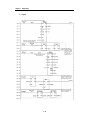
4.4 Errors Indicated During Execution of Function Block
Array
Normal run status
Ο
Ο
2
Base location No. outside the setting range
The corresponding base unit hardware
defect
Ο
Ο
3
Slot location No. outside the setting range
4
The specified slot has no thermocouple
input module
A module other than thermocouple input
module is loaded on.
Channel No. outside the setting range
Thermocouple input module hardware
defect
Thermocouple input module memory
defect
The run channel was not specified in the
Initialization function block.
Disconnection detected at one or more of
the use channels, or temperature outside
the range.
A disconnection of thermocouple or
compensating wire was detected at the use
channels
1
5
6
7
8
9
10
16
17
128
129
Remote
18
131
133
135
136
137
138
Corrective Action
Stand
alone
Item
Reading
Description
Initialization
0
Function
Block
Local
STAT No.
4.4.1 Errors Indicated by the Output Variable, STAT
Errors indicated the output variable, STAT and their corrective actions are explained.
Ο
Ο
Ο
Ο
Ο
Adjust it within the setting range
Ο
Ο
Ο
Ο
Ο
Ο
Ο
Contact a service station
Ο
Ο
Ο
Specify correctly the slot No. where the PID
control module is mounted .
Mount thermocouple input module on the
specified slot.
Mount thermocouple input module on the
specified slot.
Specify correctly the run channel.
Ο
Ο
Ο
Contact a service station.
Ο
Ο
Ο
Contact a service station.
Ο
Ο
Specify correctly run channels in the
initialization function block.
Ο
See Section 9.2.4
Ο
Out-of-the-range temperature was detected
at the used channels
Ο
Reference junction compensation device
connection defect
Remote communications module H/W
defect
Base location No. outside the setting range
Ο
Ο
Ο
Ο
Ο
Slot location No. outside the setting range
Ο
Ο
A module other than thermocouple input
module is loaded on.
Thermocouple input module hardware
defect
Thermocouple input module memory
defect
The run channel was not specified in the
initialization function block.
Disconnection detected at one or more of
the use channels, or temperature outside
the range.
Ο
Ο
Ο
Ο
Ο
Ο
Ο
Ο
Fix the disconnection of the thermocouple or
compensating wire.
Check
the
specification
of
used
thermocouple, and then use a temperature
within the defined range.
Check the connection of the reference
junction compensation device.
See Remote communications module User’s
Manual
Adjust it within the setting range
Specify correctly the slot No. where
thermocouple input module is mounted.
Mount thermocouple input module on the
specified slot.
Contact a service station.
Contact a service station.
Specify correctly run channels in the
initialization function block.
See the Section 9.2.4
4.4.2 Errors indicated by the output variable, ALM_CODE in the array type temperature conversion
value reading function block.
(G3F-TC4A : TC4ARD, TCR4RD. G4F-TC2A : TC2ARD, TCR2RD G6F-TC2A : TC2ARD, TCR62RD)
ALM_CODE No.
0
16
Description
Normal run status
Disconnection of the thermocouple or
compensating wire
17
Out-of-the range temperature
18
Reference junction compensation device
connection defect
4 -7
Corrective Action
Fix the disconnection between the thermocouple input module and
the thermocouple
Specify correctly the type of the thermocouple or use the
temperature within defined range.
Check the connection of the reference junction compensation
device.
Chapter 5. Programming
Chapter 5.
PROGRAMMING
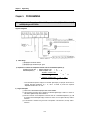
5.1 A program for Converting a Detected Temperature Value(° C) into Fahrenheit(° F)
and Outputting as a BCD Value
1) System Configuration
Display the Fahrenheit
temperature value
The lamp turns on if the Fahrenheit temperature value is negative.
The lamp turns on if disconnection occurs
% I0.0.0
The lamp turns on if the temperature conversion value is negative.
2) Initial settings
(1) Specifying the used channel: channel 0
(2) Specifying the type of the thermocouple : Type K
3) Expression for conversion of a temperature conversion value into a Fahrenheit temperature(° F)
Temperature conversion value = Detected temperature value
× 10
Fahrenheit temperature(°F)
= Detected temperature value
× 1.8 + 32
Temperature conversion value
× 1.8 +
=
10
= Temperature conversion value × 18 + 320
32
10
∴ If the Fahrenheit temperature displayed on the BCD digital display is displayed with the value of
‘detected Fahrenheit temperature (°F) × 10’, then it is needed to process the expression
“temperature conversion value × 18 + 320”.
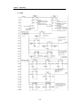
4) Program Description
(1) If %I0.0.0 turns on then the thermocouple input module would be initialized.
(2) The temperature conversion value is displayed on the BCD digital display of %Q0.2.0 to %Q0.2.19.
If the value is negative the ramp %Q0.3.2 will turn on.
(3) After the conversion of the temperature conversion value into a Fahrenheit temperature (° F), it will
be displayed on the BCD digital display of %Q0.4.0 to %Q0.4.19. If it is negative the ramp %Q0.3.0
will turn on.
(4) If disconnection is detected during conversion of temperature of the channel 0, the ramp %Q0.3.1
will turn on.
5 -1
Chapter 5. Programming
5)
Program
Base No.
Indicating the error status during
initialization function block execution
Base No.
Indicating the error status during
reading function block execution.
Slot No.
Indicating run chann el during
Initialization function block execution
Slot No.
Turns on if error is detected at used
Ch.(Allocated to %0.3.1)
Used channel specification
Used channel No.
Thermocouple type
Specification (type K)
Indicating temperature conversion
value of Ch. 0 (type
K:-200~12000)
Digital conversion value of Ch. 0
Specifying the storage for
Celsius and Fahrenheit .
Reading temp. value
has been normally
finished
If the Celsius temperature
is negative, then turn on
%Q0.3.2 and convert it
positive value.
After data type conversion
of the converted BCD is
output to the BCD digital
displaying connected to
%Q0.2.0~% Q 0.2.19.
This routine change
Celsius into Fahrenheit
If the Fahrenheit temperature
is negative, then turn on
%Q0.3.2 and convert it
positive value.
After data type conversion of
the Fahrenheit temperature, the
converted temperature is output
to the BCD digital displaying
connected to %Q0.4.0 to
% Q0. 4.19.
5 -2
Chapter 5. Programming
6) Initial Value Setting Method for I/O Variables
(1)
Channel Specification
Select this
and this screen appears
This denotes
16 channels
Select this
and this screen appears
1
Selection of the
previous channel
Channel No.
Selection of the
next channel
1
Channel enable : 1
Channel disable : 0
Channel enable/disable specification
5 -3
Chapter 5. Programming
(2)
Thermocouple Type Specification
Thermocouple type specification
Input specification No.
0
1
2
3
4
5
6
Sensor type
K
J
E
T
B
R
S
Temperature range
-200.0 to 1200.0°C
-200.0 to 800.0°C
-150.0 to 600.0°C
-200.0 to 400.0°C
400.0 to 1800.0°C
0.0 to 1750.0 °C
0.0 to 1750.0°C
5 -4
Chapter 5. Programming
7) I/O Variables Used in the Program
5 -5
Chapter 5. Programming
5.2 A program for Magnitude Comparison of a Detected Temperature Value
1)
System Configuration
2) Initial Settings
(1) Used Channel
: Channel 0 and 1
(2) Thermocouple type specification : Type K
3) Program Descriptions
(1) If the temperature that is input through the channel 0 of the thermocouple input module is less than
-20°C or larger than –30 °C, %Q0.1.0 turns on.
(2) If the temperature that is input through the channel 1 of the thermocouple input module is less than
-20°C or larger than –30 °C, %Q0.1.1 turns on.
(3) If the difference between the two temperatures that are input through the channel 0 and 1 is larger
than 5°C, %Q0.1.2 turns on.
5 -6
Chapter 5. Programming
4)
Program
Thermocouple input module
initialization has been finished.
Specifying mounted Base No.
Indicating the error status during
initialization function block execution
Specifying mounted Slot No.
Indicating run channel during
initialization function block execution
Specifying used channel
Specifying Thermocouple type (type K)
Channel 0 Reading complete.
Channel 1 Reading complete.
Base No.
Slot No.
Used Channel No.
Base
No.
Indicating the error status during Slot
reading function block execution No.
Turns On if error occurs
Used
at the Ch 1
Channel
No.
Indicating the temperature conversion value
of Ch1 (-2000~12000)
Indicating the error status during
reading function block execution
Turns On if error occurs at the Ch 0
Indicating the temperature conversion value
of Ch 0 ( -2000~12000)
Digital conversion value of Ch 0
Digital conversion value of Ch1
If the temperature detected at the
Ch 0 is less than –20 or larger
than –30%, Q0.1.0 turns on.
If the temperature detected at the
Ch 1 is less than –20 or larger
than –30%, Q0.1.0 turns on.
If the difference
between two
temperatures of
Ch 0 and 1 is
lager than 5,
Q0.1.2 turns
on.
5 -7
Chapter 5. Programming
5) I/O Variables Used in the Program
5 -8
Chapter 5. Programming
5.3 A Program Used When Mounting a Thermocouple Input Module onto the Remote I/O Station
1)
System Configuration
Local Station
No. ”0”
Remote Station
No. ”10”
Thermocouple
type K
2) Initial Settings
(1) Specifying used channel
: Channel 0
(2) Specifying thermocouple type: Type K
3)
Program Description
(1) _NET0_LIV[10] : Turns “On” if the local normally communicates with the remote.
_NET0_RST[10] : Turns “On” if communications error or power failure occurs. The user has to turn it
off forcedly when the normal state has been restored.
(2) If the temperature conversion value is negative, %Q0.3.0 will be turned “On” and the value will be
changed into a positive value.
(3) If no error has been occurred during execution of the reading function block, the temperature
conversion value will be output to “%QD0.2.0”.
5 -9
Chapter 5. Programming
4)
Program
Requests the execution of initialization function block so that the initialization
can be executed one time when the opposite station is normally operating.
Program for re -start after a power failure
has occurred during communications.
The opposite station
power failure information
If the power is restored
from fault or power-off,
then it turns ‘on’.
On remains until a user
program turns it off.
Reading Function block execution
request at every scan.
If the temperature detected at the
channel 0 is negative, then %Q0.3.0
is turned on and the value is
converted into a positive number.
MUL
Converting the data type from INT
to BCD and outputting the value
to %Q0.2.0 to %Q0.2.19.
5 - 10
Chapter 5. Programming
5) I/O Variables Used in the Program
0
5 - 11
Chapter 6. BUFFER MEMORY CONFIGURATION AND FUNCTIONS
Chapter 6. BUFFER MEMORY CONFIGURATION AND FUNCTIONS
The thermocouple-input module has the PLC CPU and the buffer memories for data communications.
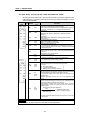
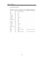
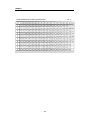
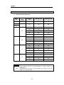
6.1 Buffer Memory Configuration
The followings describe buffer memory configuration.
Channel enable/disable Specification
Bit On(1): Enable, Bit Off(0) : Disable
1
Specifying the type of thermocouple for channel 0
2
Specifying the type of thermocouple for channel 1
3
Specifying the type of thermocouple for channel 2
4
Specifying the type of thermocouple for channel 3
5
Specifying the type of thermocouple for channel 4
6
Specifying the type of thermocouple for channel 5
7
Specifying the type of thermocouple for channel 6
8
Specifying the type of thermocouple for channel 7
9
Specifying the type of thermocouple for channel 8
10
Specifying the type of thermocouple for channel 9
11
Specifying the type of thermocouple for channel 10
12
Specifying the type of thermocouple for channel 11
13
Specifying the type of thermocouple for channel 12
14
Specifying the type of thermocouple for channel 13
15
Specifying the type of thermocouple for channel 14
16
Disable R/W
Temperature
range
0
Sensor type
Description
Input
specification
No.
Function
Read /
Write
Default
Setting
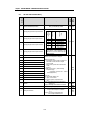
G3F-TC4A Buffer Memory
Address
(Decimal)
6.1.1
0
K
-200.0 to 1200.0°C
1
J
-200.0 to 800.0°C
2
E
-150.0 to 600.0°C
3
T
-200.0 to 400.0°C
4
B
400.0 to 1800.0°C
5
R
0.0 to 1750.0 °C
6
S
0.0 to 1750.0°C
If a value outside the defined range is set,
the bit of address 67 that corresponds to
the channel turns on and the thermocouple
type will be set to type K.
Type K R/W
Specifying the type of thermocouple for channel 15
17
Temperature conversion value of the channel 0
18
Digital conversion value of the channel 0
19
Error code of the channel 0
20
Temperature conversion value of the channel 1
21
Digital conversion value of the channel 1
22
Error code of the channel 1
23
Temperature conversion value of the channel 2
24
Digital conversion value of the channel 2
25
Error code of the channel 2
26
Temperature conversion value of the channel 3
27
Digital conversion value of the channel 3
28
Error code of the channel 3
29
Temperature conversion value of the channel 4
30
Digital conversion value of the channel 4
31
Error code of the channel 4
• Temperature conversion value
: 10 times of a real temperature is displayed.
• Digital conversion value
▶ If a temperature conversion value is converted
into a value within 0 to 16000, that value is a
digital conversion value.
▶ It can be used as a process value of the PID
control module.
▶ Expression
Digital conversion value = (16000/
measuring temperature range) ×
(temperature conversion value –
minimum measuring temperature)
• Error code
16 : Disconnection detection error
17 : Upper or lower overflow
18 : Reference junction compensation device
error
6 -1
Read
Only
Read /
Write
Function
Default
Setting
Address
(Decimal)
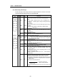
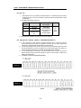
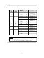
Chapter 6. BUFFER MEMORY CONFIGURATION AND FUNCTIONS
Read
Only
No
setting
R/W
Bit On(1) : Running, Bit Off(0) : Stop
Read
only
Bit On(1) : if other value than 0 to 6 is set for
specifying the type of thermocouples in
the address 1 to 16.
Bit Off(0) : If 0 to 6 is set for specifying the type of
thermocouples in the address 1 to 16.
Read
only
Description
32
Temperature conversion value of the channel 5
33
Digital conversion value of the channel 5
34
Error code of the channel 5
35
Temperature conversion value of the channel 6
36
Digital conversion value of the channel 6
37
Error code of the channel 6
38
Temperature conversion value of the channel 7
39
Digital conversion value of the channel 7
40
Error code of the channel 7
41
Temperature conversion value of the channel 8
42
Digital conversion value of the channel 8
43
Error code of the channel 8
44
Temperature conversion value of the channel 9
45
Digital conversion value of the channel 9
46
Error code of the channel 9
47
Temperature conversion value of the channel 10
48
Digital conversion value of the channel 10
49
Error code of the channel 10
50
Temperature conversion value of the channel 11
51
Digital conversion value of the channel 11
52
Error code of the channel 11
53
Temperature conversion value of the channel 12
54
Digital conversion value of the channel 12
55
Error code of the channel 12
56
Temperature conversion value of the channel 13
57
Digital conversion value of the channel 13
58
Error code of the channel 13
59
Temperature conversion value of the channel 14
60
Digital conversion value of the channel 14
61
Error code of the channel 14
62
Temperature conversion value of the channel 15
63
Digital conversion value of the channel 15
64
Error code of the channel 15
65
SET data
Bit On(1) : New setting values are set for the
contents of address 0 to 16.
Bit Off(0) : The existing values of address 0 to 16
remains.
66
Run channel information
Setting Error information
67
• Temperature conversion value
: 10 times of a real temperature is displayed.
• Digital conversion value
▶ If a temperature conversion value is converted
into a value within 0 to 16000, that value is a
digital conversion value.
▶ It can be used as a process value of the PID
control module.
▶ Expression
Digital conversion value = (16000/
measuring temperature range) ×
(temperature conversion value –
minimum measuring temperature)
• Error code
16 : Disconnection detection error
17 : Upper or lower overflow
18 : Reference junction compensation device
error
6 -2
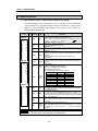
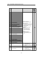
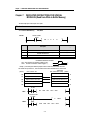
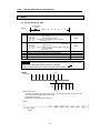
Chapter 6. BUFFER MEMORY CONFIGURATION AND FUNCTIONS
Specifying the type of thermocouple for channel 0
2
Specifying the type of thermocouple for channel 1
3
Specifying the type of thermocouple for channel 2
4
Specifying the type of thermocouple for channel 3
5
Temperature conversion value of the channel 0
6
Digital conversion value of the channel 0
7
Error code of the channel 0
8
Temperature conversion value of the channel 1
9
Digital conversion value of the channel 1
10
Error code of the channel 1
11
Temperature conversion value of the channel 2
12
Digital conversion value of the channel 2
13
Error code of the channel 2
14
Temperature conversion value of the channel 3
15
Digital conversion value of the channel 3
16
Error code of the channel 3
17
SET data
18
Run channel information
Setting error information
19
Disable R/W
Temperature
range
1
Bit On(1): Enable, Bit Off(0) : Disable
Sensor type
Channel enable/disable Specification
Input
specification
No.
0
Description
Read /
Write
Function
Default
Setting
G4F-TC2A / G6F-TC2A Buffer Memory
Address
(Decimal)
6.1.2
0
K
-200.0 to 1200.0°C
1
J
-200.0 to 800.0°C
2
E
-150.0 to 600.0°C
3
T
-200.0 to 400.0°C
4
B
400.0 to 1800.0°C
5
R
0.0 to 1750.0 °C
6
S
0.0 to 1750.0°C
If a value outside the defined range is set, the
bit of address 19 that corresponds to the
channel turns on and the thermocouple type
will be set to type K.
Type K R/W
• Temperature conversion value
: 10 times of a real temperature is displayed.
• Digital conversion value
▶ If a temperature conversion value is converted into a
value within 0 to 16000, that value is a digital
conversion value.
▶ It can be used as a process value of the PID control
module.
▶ Expression
Digital conversion value = (16000/ measuring
temperature range) ×
(temperature conversion value – minimum
measuring temperature)
• Error code
16 : Disconnection detection error
17 : Upper or lower overflow
18 : Reference junction compensation device
error
Bit On(1) : New setting values are set for the contents o
f address 0 to 4.
Bit Off(0) : The existing values of address 0 to 4 remains.
Read
Only
No
setting
R/W
Bit On(1) : Running, Bit Off(0) : Stop
Read
only
Bit On(1) : if other value than 0 to 6 is set for specifying
the type of thermocouples in the address
1 to 4.
Bit Off(0) : If 0 to 6 is set for specifying the type of
thermocouples in the address 1 to 4.
Read
only
6 -3
Chapter 6. BUFFER MEMORY CONFIGURATION AND FUNCTIONS
6.2 Buffer Memory Functions
4 Each address in the buffer memory occupies one word and it is represented with 16 bits.
4 In the 16 bits which compose an address, every bit can be set to either “1” when it should be turned On or “0”
when Off in order to implement the function of each bit.
6.2.1 Specifying Channel Enable/Disable
(G3F-TC4A : Address 0, G4F-TC2A / G6F-TC2A : Address 0)
1) Temperature conversion enable/disable specification is possible on every channel.
2) Disabling unused channels makes the sampling cycle short.
3) No specification means that all channels are disabled.
4) The followings show temperature conversion enable/disable for each channel.
G3F-TC4A
Address “0”
G4F-TC2A/G6F-TC2A
Address “0”
Specifying channel enable/disable
[Bit Off(0) : Conversion disable,
Bit On(1) : Conversion enable]
6.2.2 Specifying the Type of Thermocouple
(G3F-TC4A : Address 2 to 16, G4F -TC2A/G6F-TC2A : Address 1 to 4)
1) Type specifying the thermocouple that is connected to each channel of the thermocouple input
module is possible by the channel.
2) Default is type K.
3) The followings show the number of specification for each channel.
Specification
0
1
2
3
4
5
6
No.
Thermocouple
K
J
E
T
B
R
S
type
4)
Other value than the defined values is set for specifying the type of a thermocouple, the G3F-TC4A
displays error code at the corresponding bit in the address 67 and the G4F-TC2A/G6F-TC2A in the
address 19 with the type being specified to “0”, that is, type K thermocouple.
6 -4
Chapter 6. BUFFER MEMORY CONFIGURATION AND FUNCTIONS
6.2.3 Temperature Conversion Value
1) This area performs sampling processing of the temperature value that is inputted through the
thermocouple connected to the terminal block of a channel and stores the value of 10 times of the real
temperature value.
REMARK
If a real temperature is 123.4°C the stored value is 1234.
2) The followings show the configuration of each address.
3) If the temperature conversion specifying a channel is changed from temperature conversion enable
into temperature conversion disable, the temperature conversion value just before the change
remains.
6.2.4 Digital Conversion Value
1) A temperature value that is inputted through the thermocouple connected to the terminal block of a
channel is converted into a value between 0 to 16000, and then the converted value is stored. That
conversion is called digital conversion.
2) The digital conversion value converted to a value between 0 to 16000 can be used as a process
value of the PID control module.
3) The digital conversion value and the detected temperature value have the following arithmetic
relation.
Digital conversion value = (16000/overall measuring temperature range)
× (temperature conversion value – minimum
measuring temperature)
REMARK
If a real temperature is 123.4°C when using a type K thermocouple, since the
temperature conversion value is 1234, overall temperature range is 14000 and
minimum measuring temperature is –2000, then the digital conversion value is
(16000/14000) × [1234-(-2000)] , and it is equal to 3696 (round off at the first digit of fraction) .
Thermocouple type
K
J
E
T
B
R
S
14000
10000
7500
6000
14000
17500
17500
overall measuring
(-2000 to
(-2000 to
(-1500 to
(-2000 to
(4000 to
(0 to
(0 to
temperature range
12000)
8000)
6000)
4000)
18000)
17500)
17500)
Minimum measuring
-2000
-2000
-1500
-2000
4000
0
0
temperature
4) If the temperature conversion specifying a channel is changed from enable into disable, the digital
conversion value before the change remains
6 -5
Chapter 6. BUFFER MEMORY CONFIGURATION AND FUNCTIONS
6.2.5 Error Code
1)
Disconnection that can occur between the thermocouple and the thermocouple input module is
detected by its type, and also error information is stored when the detected temperature is outside
the defined range.
2) The following shows the types of error code.
Error Code
(Decimal)
16
17
18
Error
Data processing at an
error occurrence
RUN LED
Disconnection
Out-of-range
temperature
Reference junction
compensation device
error
The temperature
conversion value and
digital conversion value
before an error
occurrence is retained.
1 sec
cycle
flickering
3) If two or more errors are detected, the priority order is 18, then 17 and then 16.
6.2.6 Setting SET Data (G3F-TC4A : Address 65, G4F-TC2A/G6F-TC2A: Address 17)
1) If a bit corresponding to each channel in Set Data specification area is turned On(1), then the
thermocouple input module executes the temperature conversion with user -defined setting data at
the address 0 to 16 in the G3F-TC4A, and at the address 0 to 4 in the G4F-TC2A.
2) If the bit corresponding to each channel is not turned On(1), then the thermocouple input module
executes the temperature conversion not with the new user-defined setting data at the address 0 to
16 in the G3F-TC4A and at the address 0 to 4 in the G4F-TC2A but with the previous setting data.
3) If a bit0 corresponding to all channel in set data specification area is turned on(1),then the
thermocouple input module executes the temperature conversion with user-defined setting data at
address 0 to 4 in the G6F-TC2A
4) The followings show the SET data enable/disable specification
G3F-TC4A
Address “65”
G4F-TC2A
Address “17”
6 -6
Chapter 6. BUFFER MEMORY CONFIGURATION AND FUNCTIONS
Bit15 Bit14 Bit13 Bit12 Bit11 Bit10 Bit9
Bit8
Bit7 Bit6
Bit5
Bit4
-
-
Bit3
Bit2
Bit1
Bit0
ch
Address “17”
-
-
-
-
-
-
-
Ignored
-
-
-
-
-
-
Specifying channel 0~3 SET data enable/disable
[Bit Off(0): disable, Bit On(1): enable]
6.2.7 Information on Run Channel (G3F-TC4A : Address 66, G4F-TC2A/G6F-TC2A : Address 18)
This area stores information on run status of each channel.
G3F-TC4A
Address “66”
G4F-TC2A/G6F-TC2A
Address “18”
6.2.8
1)
2)
3)
Information on Thermocouple Type Specification Error
(G3F-TC4A : Address 67, G4F-TC2A/G6F-TC2A : Address 19)
If other value than “0” to “6” is set at the addresses (Address 1 to 16 in G3F-TC4A, Address 1 to 4 in
G4F-TC2A/G6F-TC2A) used for specifying the type of the thermocouple which is connected to each
channel of the thermocouple input module, error occurs.
If error occurs at a channel, then the channel runs with the type K as the type of the thermocouple.
The following shows indication of error information.
G3F-TC4A
Address “67”
G4F-TC2A/G6F-TC2A
Address “19”
6 -7
0
~3
Chapter 7. DEDICATED INSTRUCTIONS FOR SPECIAL MODULES
Chapter 7.
DEDICATED INSTRUCTIONS FOR SPECIAL
MODULES (Read from /Write to Buffer Memory)
The thermocouple input module occupies 16 I/O points.
7.1 Local
7.1.1 Read from Buffer Memory ⋅ ⋅ ⋅ GET, GETP
<Format>
execution condition
for GET
GET
n1
n2
D
n3
Format
Description
Available Data Type
n1
n2
The slot No. where the specific modules mounted
Head address of the specific module buffer memory from
which the data will be read.
Head address of the device to store the data read.
Word number of data to be read.
Integer
D
n3
Integer
M,P,K,J,T,C,D,#D
Integer
<The difference between GET and GETP>
GET: always executed if the execution condition turns On. (
GETP : executed if the execution condition is triggered. (
)
)
Example 1). In this example, the thermocouple input module is mounted on the slot 3 in the unit and the
data of buffer memory addresses 17, 18 and 19 will be read to the CPU module addresses D17, D18 and D19.
Thermocouple
(address)
CPU module D area
input module buffer memory (address)
D16
16
D17
Temp. conversion value of Ch 0
Temp. conversion value of Ch 0
17
D18
Digital conversion value of Ch 0
Digital conversion value of Ch 0
18
D19
Error code of Ch 0
Error code of Ch 0
19
D20
20
Execution condition
for GET
GET
<GET>
00003
00017
D0017
00003
Execution condition
for GETP
D
<GETP>
M0000
M0000
GETP
00003
7 -1
00017
D0017
00003
Chapter 7. DEDICATED INSTRUCTIONS FOR SPECIAL MODULES
Write to Buffer Memory ⋅ ⋅ ⋅ PUT, PUTP
7.1.2
<Format>
Execution condition
for PUT
PUT
Format
n1
n1
n2
S
n3
Description
The slot No. where the specific modules mounted
Head address of the specific module buffer memory to which the
data will be written..
Head address of the device where the data to be written has been
stored, or an integer
Word number of data to be written.
n2
S
n3
Available Data Type
Integer
Integer
M,P,K,L,T,C,D,#D
Integer
<The difference between PUT and PUTP>
PUT:
always executed if the execution condition turns On. (
)
PUTTP : executed if the execution condition is triggered. (
)
Example 1) In this example, , the thermocouple input module is mounted on the slot 6 in the unit and the data of
CPU module addresses D50 and D51 will be written to the buffer memory addresses 3 and 4.
(address)
Thermocouple
input module buffer memory
CPU module D area
(address)
D48
1
D49
2
D50
Data 1
Specifying type of thermocouple
3
D51
Data 2
Specifying type of thermocouple
4
D52
5
<PUT>
PUT
00006
00003
D0050
00002
Execution condition
for PUT
D
<PUTP>
M0000
Execution condition
for PUTP
M0000
PUTP
00006
00003
7 -2
D0050
00002
Chapter 7. DEDICATED INSTRUCTIONS FOR SPECIAL MODULES
7.2 Remote
7.2.1 Read from Buffer Memory......RGET
Execution condition
For RGET
<Format>
[
Format
SI
St
D
S
n
SS
RGET
SI
St
D
S
n
SS
Description
]
Upper(AB) : Code value for thermocouple input module
G3F – TC4A : 03h
G4F - TC2A : 83h, G6F - TC2A : 23h
Lower(CD) : Slot No. of the local communications module(FUEA)
Setting range : 0 to 7
Upper(EF) : Slot No. of the thermocouple Input module mounted on the
remote station
Setting range : 0 to 31
Lower(GH) : Station No. of the communications module mounted on the
remote station(RBEA)
Setting range : 0 to 63
Head address of the device to store the data read.
Head address of the specific module buffer memory from the data will be read
Word number of data to be read
Area used for indicating the status information during link
Available data type
Integer
Integer
M,P.K.L.T,C,D, #D
Integer
Integer, D
M,P.K.L.T,C,D, #D
REMARK
If a content is read from the buffer memory of the thermocouple input module by use of RGET, be sure to
make the program so that execution condition can transit from 0 to 1(Rising Edge :
)
Otherwise, the content in the buffer memory of the thermocouple input module is unreadable.
Slot 4
<Example>
[Configuration]
GM3 PA1A
GM3 CPUA
G3ID24A
G3ID22A
G3QRY4A
G3QRY2A
G3LFUEA
Slot 1
GM3 PA1A
G3LRBEA
G3ID24A
Station No. 11
G3FTC4A
(0Bh)
[Read from buffer memory]
1) The content in the buffer memory address 17(one word) is read, where the temperature conversion value of the
channel 0 of the thermocouple input module had been started.
2) The data read is stored to D17
3) Information on the communications status is stored to D1
[Program]
Execution condition
for RGET
7 -3
Chapter 7. DEDICATED INSTRUCTIONS FOR SPECIAL MODULES
7.2.2 Write to buffer memory ..... RPUT
Execution condition
For RPUT
<Format>
[
Format
SI
RPUT
SI
St
S
D
n
SS
]
Description
Upper(AB) : Code value for thermocouple input module
G3F – TC4A : 03h
G4F - TC2A : 83h ,G6F - TC2A : 23h
Lower(CD) : Slot No. of the local communications module(FUEA)
Setting range : 0 to 7
Upper(EF) : Slot No. of the thermocouple
Input module mounted on the remote station
Setting range : 0 to 31
Lower(GH) : Station No. of the communications module mounted on the
remote station(RBEA)
Setting range : 0 to 63
Head address of the device to be stored the data write.
Head address of the specific module's head address to write data
Word number of data to be write
Area used for indicating the status information during link
St
S
D
n
SS
Available data type
Integer
Integer
M,P.K.L.T,C,D, #D
Integer
Integer, D
M,P.K.L.T,C,D, #D
REMARK
If the content is write to the buffer memory of the thermocouple input module by use of RPUT, be sure to
make the program so that execution condition can transit from 0 to 1(Rising Edge :
)
Otherwise, the content in the buffer memory of the thermocouple input module will not be changed with a
new data.
Slot 4
<Example>
[Configuration]
GM3 PA1A
GM3 CPUA
G3ID24A
G3ID22A
G3QRY4A
G3QRY2A
G3LFUEA
Slot 1
GM3 PA1A
G3LRBEA
G3ID24A
G3FTC4A
Station No. 11
(0Bh)
[Write to buffer memory]
1) The content in the D100 to D116(17 words) of the devices in the CPU module
2) is written to addresses 0 to 16 of the buffer memory of the thermocouple input module, and
3) Information on the communication status is stored to D0
[Program]
RPUT h 0 3 0 4 h 0 1 0 B
Execution condition
for RPUT
7 -4
D0100 00000 00017 D0000
Chapter 8. PROGRAMMING
Chapter 8.
8.1
PROGRAMMING
Basic Programming
The following describes the method to set the running conditions in the buffer memories of the thermocoupleinput module.
The thermocouple input module is already mounted on the slot 2.
The thermocouple input module occupies 16 I/O points.
8.1.1
G3F-TC4A
Slot No.
Buffer
memory
address
.
Numbers
of words
Setting
to be
data. written
Specifying used channel
(Channel 0 to 15)
Specifying the type K
thermocouple (Channel 0 to 3)
Specifying the type J
thermocouple (Channel 4 and 5)
Specifying the type E
thermocouple (Channel 6 and 7)
Specifying the type T
thermocouple (Channel 8 and 9)
Specifying the type B
thermocouple (Channel 10 and 11)
Specifying the type R
thermocouple (Channel 12 and 13)
Specifying the type S
thermocouple (Channel 14 and 15)
Changing every channel with SET
data whenever the data of buffer
memory address 0 to 16 is newly
written.
Device to be stored
Number of
words to be read
Reading the temperature conversion
value of channel 0
Reading the digital con version
value of channel 0
Reading the error code
of channel 0
Reading the temperature conversion
value, digital conversion value and
error code of channel 1 to 15.
Reading run information
(1 : Run, 0 : Stop)
Reading the thermocouple type
specification error information
(Bit On(1) : Setting error,
Bit Off(0) : Normal)
8 -1
Chapter 8. PROGRAMMING
8.1.2
G4F-TC2A
Slot No.
Buffer
memory
address
.
Numbers
of words
Setting
to be
data.
written
Specifying used channel
(Channel 0 to 15)
Specifying the type K
thermocouple (Channel 0)
Specifying the type 5
thermocouple (Channel 1)
Specifying the type E
thermocouple (Channel 2)
Specifying the typeT
thermocouple (Channel 3)
Number of
Device to be stored words
to be read
Changing every channel with SET
data whenever the data of buffer
memory address 0 to 4 is newly
written.
Reading the temperature conversion
value of channel 0
Reading the digital conversion
value of channel 0
Reading the error code
of channel 0
Reading the temperature conversion
value, digital conversion value and
error code of channel 1 to 3.
Reading run information
(1 : Run, 0 : Stop)
Reading the thermocouple type
specification error information
(Bit On(1) : Setting error,
Bit Off(0) : Normal)
8 -2
Chapter 8. PROGRAMMING
8.1.3
G6F-TC2A
Slot No.
Buffer
memory
address
.
Numbers
of words
Setting
to be
data.
written
Specifying used channel
(Channel 0 to 15)
Specifying the type K
thermocouple (Channel 0)
Specifying the type 5
thermocouple (Channel 1)
Specifying the type E
thermocouple (Channel 2)
Specifying the type T
thermocouple (Channel 3)
h0001
Changing every channel with SET
data whenever the data of buffer
memory address 0 to 4 is newly
written.
Number of
Device to be stored words
to be read
Reading the temperature conversion
value of channel 0
Reading the digital conversion
value of channel 0
Reading the error code
of channel 0
Reading the temperature conversion
value, digital conversion value and
error code of channel 1 to 3.
Reading run information
(1 : Run, 0 : Stop)
Reading the thermocouple type
specification error information
(Bit On(1) : Setting error,
Bit Off(0) : Normal)
8 -3
Chapter 8. PROGRAMMING
8.2 Application Programming
8.2.1
A program for Conversing a Detected Temperature Value(° C) into Fahrenheit(° F) and Outputting
as a BCD Value
1) System
GM3 - GM3 PA1A CPUA
S
G3ID24A
G3FTC4A
G3Q RY4A
G3QRY2A
S
G3QRY4A
BCD digital display.
[Display the Fahrenheit
temperature value]
Thermocouple
input module
initial setting
The lamp turns on if the Fahrenheit temperature value is negative
The lamp turns on if disconnection occurs
Thermocouple type K
The lamp turns on if the temperature conversion value is negative
BCD digital display.
[Display the temperature
conversion value]
2) Initial Setting
(1) Specifying used channel : Channel 0
(2) Specifying the type of the thermocouple : Type K
3) Expression for conversion of a temperature conversion value into a Fahrenheit temperature(° F)
Temperature conversion value = Detected temperature value × 10
Fahrenheit temperature(°F)
= Detected temperature value × 1.8 + 32
Temperature conversion value
=
× 1.8 +
10
= Temperature conversion value × 18 + 320
32
10
4)
Program Description
(1) If P0000 turns on then the thermocouple input module would be initialized.
(2) The temperature conversion value is displayed on the BCD digital display of P0020 to P0033 If the
value is negative the ramp P0042 will turn on.
(3) After the conversion of the temperature conversion value into a Fahrenheit temperature (° F), it will
be displayed on the BCD digital display ofP0050 to P0063. If it is negative the ramp P0040 will
turn on.
(4) If disconnection is detected during conversion of temperature of the channel 0, the ramp P0041 will
turn on.
8 -4
Chapter 8. PROGRAMMING
5)
Program
Initialization
command
Initialization command
Specifying the type K thermocouple for channel 0
Thermocouple
input module
initialization
Specifying thermocouple input module SET data enable
Reading the temperature conversion value of channel 0 to D17
Reading the error code of channel 0 to D19
Reading thermocouple type specification error information to D67
P41 is turned on if disconnection is detected at the channel 0.
M1 is turned on if no error
has occurred at the channel 0
Separating the areas where Celsius and Fahrenheit temperatures will be stored.
If the Celsius temperature is negative,
P42 is turned on and it is changed into
a positive number.
Outputting the Celsius temperature as
a BCD value (P0020 to P0033)
If the Fahrenheit temperature is negative,
P40 is turned on and it is changed into a
positive number.
Outputting the Fahrenheit temperature
as a BCD value (P0050 to P0063)
8 -5
Chapter 8. PROGRAMMING
8.2.2
1)
A Program for Magnitude Comparison of a Detected Temperature Value
System Configuration
GM3PA1A
2)
GM3CPUA
G3FTC4A
G3QRY2A
Initial Settings
(1) Specifying used channel : Channel 0, 1
(2) Specifying the type of the thermocouple : Type K
3)
Program Description
(1) If the temperature that is input through the channel 0 of the thermocouple input module is less
than -20°C or larger than –30 °C, P0010 turns on.
(2) If the temperature that is input through the channel 1 of the thermocouple input module is less
than -20°C or larger than –30 °C, P0011 turns on.
(3) If the difference between the two temperatures that are input through the channel 0 and 1 is
larger than 5°C, P0012 turns on.
8 -6
Chapter 8. PROGRAMMING
4)
Program
Specifying the channel 0 and 1 enable
Specifying the Type K for thermocouples of channel 0 and 1.
Specifying thermocouple input module SET data enable
Reading the temperature conversion value of channel 0 to D17
Reading the error code of channel 0 to D19
Reading the temperature conversion value of channel 1 to D20
Reading the error code of channel 1 to D22
Reading thermocouple type specification error information to D67
M1 is turned on if error occurs at the channel 0.
M2 is turned on if error occurs at the channel 1.
If the temperature of the channel 0 is less than
-20℃ and larger than -30℃, P10 is turned on.
If the temperature of the channel 1 is less than
-20℃ and larger than -30℃, P11 is turned on.
Storing the difference between two temperatures of channel 0 and 1 to D0100
P12 turns on if the
difference between two
temperatures of channel 0
and 1 is larger than 5 ℃,
8 -7
Thermocouple
input module
initialization
Chapter 8. PROGRAMMING
8.2.3
1)
A Program Used When Mounting a Thermocouple Input Module on the Remote I/O Station
System Configuration
GM3PA1A
GM3CPUA
G3LFUEA
G3ID22A
G3QTR4A
G3QTR2A
P0040
(P0020 to P0033)
GM3PA1A
G3LRBEA
G3FTC4A
Thermocouple type K
2) Initial Settings
(1) Specifying used channel : Channel 0
(2) Specifying the type of the thermocouple : Type K
3) Program Description
(1) P0040 will be turned on if the temperature conversion value is negative and the value will be converted
into positive.
(2) If no error occurs, the temperature conversion value will be output to P0020 to P0033.
8 -8
Chapter 8. PROGRAMMING
4)
Program
Specifying channel 0 enable
Slot No. of
Specifying the type of thermocouple for
thermocouple input
Thermocouple input module that is mounted Head address of the buffer channel 0 to type K
module code on the remote station
memory to be written
Remote Head address of the
Local communications station No. device where the data to
module Slot No.
be writes is stored.
Writing the value
stored at D0,D1
to buffer memory
address 0
and 1.
Numbers of Communication
words that will information
be writes
Channel 0 SET data enable specification
Channel SET data
enable specification
Turns on M0 and M10 if no
communication error
has occurred
Temperature
conversion
value
Digital value
Reading
error code
Reading the thermocouple specification error information from D67
M111 turns on if error occurs at
the channel 0
If the
temperature
conversion value
is negative, then
P40 is turned on
and converted
into a positive
Outputting the
temperature conversion
value to the BCD display.
(P0020 to P0033)
8 -9
Chapter 9.
TROUBLESHOOTING
Chapter 9.
TROUBLESHOOTING
The followings explain errors that could occur during operating the thermocouple input module and their
troubleshooting.
9.1 Errors Indicated by RUN LED Flickering
Errors indicated by the thermocouple input module RUN LED flickering are given below.
RUN LED Status
Flickering (cycle: 0.1 sec)
Flickering (cycle: 0.2 sec)
Flickering (cycle: 0.6 sec)
Flickering (cycle: 1.0 sec)
Flickering (cycle: 1.0 sec)
Flickering (cycle: 1.0 sec)
Error Type
WDT error
System error
Buffer memory error
A/D conversion error
Disconnection
Outside the upper or lower
bound of the range
Reference junction
compensation device error
Remark
The data before error has
occurred is retained
The data before error has
occurred is retained
9.2 Troubleshooting Procedure
9.2.1 RUN LED Flickering
RUN LED flickering
The thermocouple input module is correctly
mounted onto the base board.
No
Yes
RUN LED flickering with 1 sec cycle.
Mount correctly the
module onto the base board.
thermocouple-input
Connection fault or disconnection or the
reference junction compensation device, or
input temperature out-of range error
Yes
No
Refer to General Section 9.2.5
9- 1
Chapter 9.
TROUBLESHOOTING
9.2.2
RUN LED Off
RUN LED off
The thermocouple-input module is correctly mounted onto
the base board
Mount correctly the thermocouple-input module on the base
board.
No
.
Yes
The capacity of the power supply module on the base board
is sufficient
Re-examine system configuration with calculating the
consumption current of each module.
No
Yes
If the thermocouple input module that has error is replaced
with another one, then the system normally operates.
See Section 9.2.5
No
Yes
Fault of other modules than thethermocouple input module.
For details, refer the CPU module user's Manual.
9.2.3
Temperature Conversion Value Fluctuates Excessively
Temperature conversion value fluctuates excessively.
Compensating wire is shielded.
Replace with a shielded compensating wire.
No
Yes
Shied wire of compensating wire is connected to the FG
terminal of the thermocouple input module.
Connect the shied wire of compensating
wire to the FG terminal of the
thermocouple input module.
No
Yes
The terminal FG of the thermocouple input module is
grounded.
Ground the terminal FG of the
thermocouple input module.
No
Yes
The thermocouple input module hardware defect
See General Section 9.2.5
9- 2
Chapter 9.
TROUBLESHOOTING
9.2.4 Input Value of the Thermocouple does not Correspond to the Detected Temperature Value.
Input value of the thermocouple is not consistent with the
temperature conversion value.
The specified type for the used thermocouple of the
corresponding channel is not consistent with the type of the
connected thermocouple.
Check the type of the thermocouple and
correctly specify the type
No
Yes
The compensating wire is correctly used in accordance with
the used thermocouple.
Use the compensating wire suitable to the
used thermocouple.
No
Yes
The wiring between the thermocouple input module and
the thermocouple is correct.
Correctly wire with reference to the Section
3.2 ‘Wiring’
No
Yes
TC□RD: Error No. 16 is being indicated.
TC□ARD: Error No. 10 is being indicated, and 16 are
indicated on the variable ALM_CODE by each
channel.
Disconnection occurred. Check the
disconnection of the thermocouple or
compensating wire.
No
Yes
TC□RD: Error No. 17 is being indicated.
TC□ARD:Error No. 10 is being indicated, and 17 is
indicated on the variable ALM_CODE by each
channel.
The input temperature value is out of the
range. Check that the thermocouple is
correctly specified and input a temperature
No
Yes
value within the defined range.
The reference junction compensation device is correctly
screwed onto the terminal block.
Check the screwing state of the reference
junction compensation device to the terminal
block
No
Yes
See Section 9.2.5
9.2.5
Thermocouple Input Module Hardware Defect
Thermocouple input module hardware defect.
Contact the nearest agency or service station
9- 3
Chapter 10. DIMENSIONS
Chapter 10.
DIMENSIONS
10.1 G3F-TC4A Dimensions.
10 - 1
Chapter 10. DIMENSIONS
10.2 G4F-TC2A Dimensions
10 - 2
Chapter 10. DIMENSIONS
10.3 G6F-TC2A Dimensions.
Unit:㎜
RUN
G6F-TC2A
110.0
RJ
+
+
CH1 CH0
CH2
+
-
CH3
+
FG
INPUT
TYPE:
K,J,E
100.0
35.0
10 - 3
APPENDIX 1.
APPENDIX 1.
1.1 Thermoelectromotive Force Tables
4Standard thermoelctromotive force tabl es for type K thermocouples
Temp
(℃)
Temp
(℃)
4Standard thermoelctromotive force tables for type J thermocouples
Temp.(℃) Temp.(℃ )
A -1
Unit : µV
APPENDIX 1.
4Standard thermoelctromotive force tables for type E thermocouples
Temp.(℃)
Temp.(℃ )
4Standard thermoelctromotive force tables for type T thermocouples
Temp.(℃)
Temp.(℃ )
A -2
Unit : µV
APPENDIX 1.
4Standard thermoelctromotive force tables for type B thermocouples
Temp.
(℃)
4Standard thermoelctromotive force tables for type R thermocouples
Temp.
(℃)
A -3
Unit : µV
APPENDIX 1.
4Standard thermoelctromotive force tables for type S thermocouples
Temp.
(℃ )
A -4
Unit : µV
APPENDIX 1.
1.2 Thermocouple
1.2.1 Normal and Overheat Temperature Limits
Material
Code
B
R
S
K
E
J
T
Previous
Code
Wire Diameter
(mm)
Normal
Temperature Limit (1)
°C
Overheat
Temperature Limit (2)
°C
−
0.50
1500
1700
−
0.50
1400
1600
0.65
650
850
1.00
750
950
1.60
850
1050
2.30
900
1100
3.20
1000
1200
0.65
450
500
1.00
500
550
1.60
550
650
2.30
600
750
3.20
700
800
0.65
400
500
1.00
450
550
1.60
500
650
2.30
550
750
3.20
600
750
0.32
200
250
0.65
200
250
1.00
250
300
1.60
300
300
(reference)
CA
CRC
IC
CC
REMARK
Note (1) : Normal temperature limit refers to the limit temperature for continuous operation of the
thermocouple in air.
Note (2) : Overheat temperature limit refers to the limit temperature only available for short period
operation in a very necessary condition.
A -5
APPENDIX 1.
1.2.2 Temperature Tolerances
Material
Code
Previous Code
(reference)
Measured
temperature range
°C
Class
B
−
600 to 1700
0.5
R
S
−
0 to 1600
0.25
0 to 1000
0.4
0 to 1200
0.75
-200 to 0
1.5
0 to 800
0.4
0 to 800
0.75
-200 to 0
1.5
0 to 750
0.4
0 to 750
0.75
0 to 350
0.4
0 to 350
0.75
-200 to 0
1.5
K
E
J
T
CA
CRC
IC
CC
Tolerance (1)
± 4 °C or measured
temperature ± 0.5%
± 1.5 °C or measured
temperature ± 0.25%
± 1.5 °C or measured
temperature ± 0.4%
± 2.5 °C or measured
temperature ± 0.75%
± 2.5 °C or measured
temperature ± 1.5%
± 1.5 °C or measured
temperature ± 0.4%
± 2.5 °C or measured
temperature ± 0.75%
± 2.5 °C or measured
temperature ± 1.5%
± 1.5 °C or measured
temperature ± 0.4%
± 2.5 °C or measured
temperature ± 0.75%
± 0.5 °C or measured
temperature ± 0.4%
± 1 °C or measured
temperature ± 0.75%
± 1 °C or measured
temperature ± 1.5%
REMARK
Note (1) : Tolerance refer to the maximum permitted limit of the difference in temperature between the
temperature looked up in a standard thermoelectromotive force table corresponding to the
thermoelectromotive force, and the measuring junction temperature.
The tolerance is taken as the large of the temperature (°C) and percentage (%) values.
A -6
APPENDIX 1.
1.3 Compensating Wire
K
CA
WCA-G
General
/Normal
WX-H
WCA-H
Heat tolerance
/Normal
VX-G
WCA-G
General
/Normal
EX-G
WCRCG
General
/Normal
EX-H
WCRCH
Heat tolerance
/Normal
JX-G
WIC-G
General
/Normal
WX-G
E
J
T
CRC
IC
JX-H
WIC-H
TX-G
WCC-C
TX-GS
-
CC
TX-H
WCC-H
TX-HS
-
Heat tolerance
/Normal
General
/Normal
General
/Precision
Heat tolerance
/Normal
Heat tolerance
/Precision
-20
to
90
0 to
150
Fi
Cu/Ni
alloy
Cu
Cu/Ni
alloy
Ni/Cr
alloy
Cu/Ni
alloy
Fi
Cu/Ni
alloy
Cu
Cu/Ni
alloy
0 to
150
-20
to
90
0 to
150
-20
to
90
-20
to
90
0 to
150
-20
to
90
0 to
150
-20
to
90
0 to
150
-20 to
150
(2)
0.1
black
red
white
blue
red
white
1.5
violet
red
white
0.8
yellow
red
white
0.8
brown
red
white
±
2.5
±
1.5
±
2.5
±
1.5
1.5
±
3.0
0.5
-20 to
100
0.8
±
2.5
-20 to
150
±
2.0
±
1.0
±
2.0
±
1.0
Remark
Color of Core
fiber
white
+3
-7
Compensatio
n type
WCAHS
red
compensation
type
KX-HS
gray
expansion type
WCA-H
Ni
alloy
0.0
5
compensation type
KX-H
Ni/Cr
alloy
- (1)
expansion
type
WCAGS
0 to
100
-
expansion
type
KXGS
Cu/Ni
alloy
+
expansion type
WCA-G
Cu
0 to
90
0 to
90
0 to
150
Color of surface fiber
KX-G
S
Cu
Wire dielectrics(Ω )(3)
-
R
Cu
Compensating wire error
tolerance(Ω )
-
RX-G
SX-G
RX-H
SX-H
General
/Normal
General
/Normal
Heat tolerance
/Normal
General
/Normal
General
/Precision
Heat tolerance
/Normal
Heat tolerance
/Precision
Junction temperature
(° C)
-
Operating temperature( ° C)
Material
Previous code
BX-G
- part
Code
-
+ part
Previous code
B
Class
Code
Combined
thermocouple
Compensating
wire
1.3.1 Types and Specifications of Compensating Wire
REMARK
Note (1) : The BX-G uses same material core(Cu) on the two parts of + and -. Therefore, error tolerance is not
defined.
Note (2) : The thermocouple type R and S’s thermelectromotive force characteristics is non-linear, so it is not real
measurement error of temperatures.
Note (3) : This should be applied to the wires of 1.25 mm 2 or more section area.
A -7